EP4290050A1 - Aircraft engine having downstream and upstream stator vanes of different numbers and made of different materials - Google Patents
Aircraft engine having downstream and upstream stator vanes of different numbers and made of different materials Download PDFInfo
- Publication number
- EP4290050A1 EP4290050A1 EP23173772.7A EP23173772A EP4290050A1 EP 4290050 A1 EP4290050 A1 EP 4290050A1 EP 23173772 A EP23173772 A EP 23173772A EP 4290050 A1 EP4290050 A1 EP 4290050A1
- Authority
- EP
- European Patent Office
- Prior art keywords
- vane
- stator
- downstream
- vanes
- upstream
- Prior art date
- Legal status (The legal status is an assumption and is not a legal conclusion. Google has not performed a legal analysis and makes no representation as to the accuracy of the status listed.)
- Granted
Links
Images


Classifications
-
- F—MECHANICAL ENGINEERING; LIGHTING; HEATING; WEAPONS; BLASTING
- F01—MACHINES OR ENGINES IN GENERAL; ENGINE PLANTS IN GENERAL; STEAM ENGINES
- F01D—NON-POSITIVE DISPLACEMENT MACHINES OR ENGINES, e.g. STEAM TURBINES
- F01D9/00—Stators
- F01D9/02—Nozzles; Nozzle boxes; Stator blades; Guide conduits, e.g. individual nozzles
- F01D9/04—Nozzles; Nozzle boxes; Stator blades; Guide conduits, e.g. individual nozzles forming ring or sector
-
- F—MECHANICAL ENGINEERING; LIGHTING; HEATING; WEAPONS; BLASTING
- F01—MACHINES OR ENGINES IN GENERAL; ENGINE PLANTS IN GENERAL; STEAM ENGINES
- F01D—NON-POSITIVE DISPLACEMENT MACHINES OR ENGINES, e.g. STEAM TURBINES
- F01D21/00—Shutting-down of machines or engines, e.g. in emergency; Regulating, controlling, or safety means not otherwise provided for
- F01D21/04—Shutting-down of machines or engines, e.g. in emergency; Regulating, controlling, or safety means not otherwise provided for responsive to undesired position of rotor relative to stator or to breaking-off of a part of the rotor, e.g. indicating such position
- F01D21/045—Shutting-down of machines or engines, e.g. in emergency; Regulating, controlling, or safety means not otherwise provided for responsive to undesired position of rotor relative to stator or to breaking-off of a part of the rotor, e.g. indicating such position special arrangements in stators or in rotors dealing with breaking-off of part of rotor
-
- F—MECHANICAL ENGINEERING; LIGHTING; HEATING; WEAPONS; BLASTING
- F01—MACHINES OR ENGINES IN GENERAL; ENGINE PLANTS IN GENERAL; STEAM ENGINES
- F01D—NON-POSITIVE DISPLACEMENT MACHINES OR ENGINES, e.g. STEAM TURBINES
- F01D5/00—Blades; Blade-carrying members; Heating, heat-insulating, cooling or antivibration means on the blades or the members
- F01D5/12—Blades
- F01D5/14—Form or construction
- F01D5/141—Shape, i.e. outer, aerodynamic form
-
- F—MECHANICAL ENGINEERING; LIGHTING; HEATING; WEAPONS; BLASTING
- F01—MACHINES OR ENGINES IN GENERAL; ENGINE PLANTS IN GENERAL; STEAM ENGINES
- F01D—NON-POSITIVE DISPLACEMENT MACHINES OR ENGINES, e.g. STEAM TURBINES
- F01D5/00—Blades; Blade-carrying members; Heating, heat-insulating, cooling or antivibration means on the blades or the members
- F01D5/12—Blades
- F01D5/14—Form or construction
- F01D5/141—Shape, i.e. outer, aerodynamic form
- F01D5/142—Shape, i.e. outer, aerodynamic form of the blades of successive rotor or stator blade-rows
-
- F—MECHANICAL ENGINEERING; LIGHTING; HEATING; WEAPONS; BLASTING
- F01—MACHINES OR ENGINES IN GENERAL; ENGINE PLANTS IN GENERAL; STEAM ENGINES
- F01D—NON-POSITIVE DISPLACEMENT MACHINES OR ENGINES, e.g. STEAM TURBINES
- F01D5/00—Blades; Blade-carrying members; Heating, heat-insulating, cooling or antivibration means on the blades or the members
- F01D5/12—Blades
- F01D5/14—Form or construction
- F01D5/141—Shape, i.e. outer, aerodynamic form
- F01D5/146—Shape, i.e. outer, aerodynamic form of blades with tandem configuration, split blades or slotted blades
-
- F—MECHANICAL ENGINEERING; LIGHTING; HEATING; WEAPONS; BLASTING
- F01—MACHINES OR ENGINES IN GENERAL; ENGINE PLANTS IN GENERAL; STEAM ENGINES
- F01D—NON-POSITIVE DISPLACEMENT MACHINES OR ENGINES, e.g. STEAM TURBINES
- F01D25/00—Component parts, details, or accessories, not provided for in, or of interest apart from, other groups
- F01D25/24—Casings; Casing parts, e.g. diaphragms, casing fastenings
- F01D25/246—Fastening of diaphragms or stator-rings
-
- F—MECHANICAL ENGINEERING; LIGHTING; HEATING; WEAPONS; BLASTING
- F01—MACHINES OR ENGINES IN GENERAL; ENGINE PLANTS IN GENERAL; STEAM ENGINES
- F01D—NON-POSITIVE DISPLACEMENT MACHINES OR ENGINES, e.g. STEAM TURBINES
- F01D5/00—Blades; Blade-carrying members; Heating, heat-insulating, cooling or antivibration means on the blades or the members
- F01D5/12—Blades
- F01D5/28—Selecting particular materials; Particular measures relating thereto; Measures against erosion or corrosion
-
- F—MECHANICAL ENGINEERING; LIGHTING; HEATING; WEAPONS; BLASTING
- F01—MACHINES OR ENGINES IN GENERAL; ENGINE PLANTS IN GENERAL; STEAM ENGINES
- F01D—NON-POSITIVE DISPLACEMENT MACHINES OR ENGINES, e.g. STEAM TURBINES
- F01D9/00—Stators
- F01D9/02—Nozzles; Nozzle boxes; Stator blades; Guide conduits, e.g. individual nozzles
- F01D9/04—Nozzles; Nozzle boxes; Stator blades; Guide conduits, e.g. individual nozzles forming ring or sector
- F01D9/041—Nozzles; Nozzle boxes; Stator blades; Guide conduits, e.g. individual nozzles forming ring or sector using blades
-
- F—MECHANICAL ENGINEERING; LIGHTING; HEATING; WEAPONS; BLASTING
- F01—MACHINES OR ENGINES IN GENERAL; ENGINE PLANTS IN GENERAL; STEAM ENGINES
- F01D—NON-POSITIVE DISPLACEMENT MACHINES OR ENGINES, e.g. STEAM TURBINES
- F01D9/00—Stators
- F01D9/02—Nozzles; Nozzle boxes; Stator blades; Guide conduits, e.g. individual nozzles
- F01D9/04—Nozzles; Nozzle boxes; Stator blades; Guide conduits, e.g. individual nozzles forming ring or sector
- F01D9/042—Nozzles; Nozzle boxes; Stator blades; Guide conduits, e.g. individual nozzles forming ring or sector fixing blades to stators
-
- F—MECHANICAL ENGINEERING; LIGHTING; HEATING; WEAPONS; BLASTING
- F05—INDEXING SCHEMES RELATING TO ENGINES OR PUMPS IN VARIOUS SUBCLASSES OF CLASSES F01-F04
- F05D—INDEXING SCHEME FOR ASPECTS RELATING TO NON-POSITIVE-DISPLACEMENT MACHINES OR ENGINES, GAS-TURBINES OR JET-PROPULSION PLANTS
- F05D2220/00—Application
- F05D2220/30—Application in turbines
- F05D2220/32—Application in turbines in gas turbines
- F05D2220/323—Application in turbines in gas turbines for aircraft propulsion, e.g. jet engines
-
- F—MECHANICAL ENGINEERING; LIGHTING; HEATING; WEAPONS; BLASTING
- F05—INDEXING SCHEMES RELATING TO ENGINES OR PUMPS IN VARIOUS SUBCLASSES OF CLASSES F01-F04
- F05D—INDEXING SCHEME FOR ASPECTS RELATING TO NON-POSITIVE-DISPLACEMENT MACHINES OR ENGINES, GAS-TURBINES OR JET-PROPULSION PLANTS
- F05D2230/00—Manufacture
- F05D2230/60—Assembly methods
-
- F—MECHANICAL ENGINEERING; LIGHTING; HEATING; WEAPONS; BLASTING
- F05—INDEXING SCHEMES RELATING TO ENGINES OR PUMPS IN VARIOUS SUBCLASSES OF CLASSES F01-F04
- F05D—INDEXING SCHEME FOR ASPECTS RELATING TO NON-POSITIVE-DISPLACEMENT MACHINES OR ENGINES, GAS-TURBINES OR JET-PROPULSION PLANTS
- F05D2240/00—Components
- F05D2240/10—Stators
- F05D2240/12—Fluid guiding means, e.g. vanes
- F05D2240/121—Fluid guiding means, e.g. vanes related to the leading edge of a stator vane
-
- F—MECHANICAL ENGINEERING; LIGHTING; HEATING; WEAPONS; BLASTING
- F05—INDEXING SCHEMES RELATING TO ENGINES OR PUMPS IN VARIOUS SUBCLASSES OF CLASSES F01-F04
- F05D—INDEXING SCHEME FOR ASPECTS RELATING TO NON-POSITIVE-DISPLACEMENT MACHINES OR ENGINES, GAS-TURBINES OR JET-PROPULSION PLANTS
- F05D2240/00—Components
- F05D2240/20—Rotors
- F05D2240/30—Characteristics of rotor blades, i.e. of any element transforming dynamic fluid energy to or from rotational energy and being attached to a rotor
- F05D2240/303—Characteristics of rotor blades, i.e. of any element transforming dynamic fluid energy to or from rotational energy and being attached to a rotor related to the leading edge of a rotor blade
-
- F—MECHANICAL ENGINEERING; LIGHTING; HEATING; WEAPONS; BLASTING
- F05—INDEXING SCHEMES RELATING TO ENGINES OR PUMPS IN VARIOUS SUBCLASSES OF CLASSES F01-F04
- F05D—INDEXING SCHEME FOR ASPECTS RELATING TO NON-POSITIVE-DISPLACEMENT MACHINES OR ENGINES, GAS-TURBINES OR JET-PROPULSION PLANTS
- F05D2250/00—Geometry
- F05D2250/30—Arrangement of components
- F05D2250/31—Arrangement of components according to the direction of their main axis or their axis of rotation
- F05D2250/312—Arrangement of components according to the direction of their main axis or their axis of rotation the axes being parallel to each other
-
- F—MECHANICAL ENGINEERING; LIGHTING; HEATING; WEAPONS; BLASTING
- F05—INDEXING SCHEMES RELATING TO ENGINES OR PUMPS IN VARIOUS SUBCLASSES OF CLASSES F01-F04
- F05D—INDEXING SCHEME FOR ASPECTS RELATING TO NON-POSITIVE-DISPLACEMENT MACHINES OR ENGINES, GAS-TURBINES OR JET-PROPULSION PLANTS
- F05D2300/00—Materials; Properties thereof
- F05D2300/10—Metals, alloys or intermetallic compounds
- F05D2300/12—Light metals
- F05D2300/121—Aluminium
-
- F—MECHANICAL ENGINEERING; LIGHTING; HEATING; WEAPONS; BLASTING
- F05—INDEXING SCHEMES RELATING TO ENGINES OR PUMPS IN VARIOUS SUBCLASSES OF CLASSES F01-F04
- F05D—INDEXING SCHEME FOR ASPECTS RELATING TO NON-POSITIVE-DISPLACEMENT MACHINES OR ENGINES, GAS-TURBINES OR JET-PROPULSION PLANTS
- F05D2300/00—Materials; Properties thereof
- F05D2300/10—Metals, alloys or intermetallic compounds
- F05D2300/17—Alloys
- F05D2300/171—Steel alloys
Definitions
- aircraft engines such as turbofan engines
- FOD foreign object damage
- a foreign object e.g., ice
- the damaged airfoil is typically impacted at its leading edge. This may result in performance loss, imbalance, and so on. Improvements are therefore sought.
- an aircraft engine comprising: an upstream stator having upstream stator vanes circumferentially distributed about a central axis; and a downstream stator having downstream stator vanes circumferentially distributed about the central axis, the downstream stator located downstream of the upstream stator relative to an airflow flowing within a core gaspath of the aircraft engine, a number of the upstream stator vanes being different than a number of the downstream stator vanes, the downstream stator vanes including: a first vane made of a first material, a major portion of a leading edge of the first vane circumferentially overlapped by one of the upstream stator vanes, and a second vane made of a second material having a greater stiffness, strength, and/or ductility than that of the first material, a major portion of a leading edge of the second vane exposed via a spacing defined between two of the upstream stator vanes.
- the major portion of the leading edge include at least 50% of a span of the downstream stator vanes.
- the major portion includes a tip section.
- the first material is aluminum and the second material is steel.
- zones are circumferentially distributed about the central axis where major portions of leading edges of the downstream stator vanes are exposed via the spacing, the first vane located between two of the zones, the second vane located within one of the zones.
- the stiffness of the second material is at least two times greater than that of the first material.
- the downstream stator includes vane segments distributed about the central axis, each of the vane segments having one or more of the downstream stator vanes.
- the vane segments include a first vane segment each including the first vane, and a second vane segment including the second vane.
- a stator assembly comprising: an upstream stator having upstream stator vanes circumferentially distributed about a central axis; and a downstream stator having downstream stator vanes circumferentially distributed about the central axis, the downstream stator located downstream of the upstream stator relative to an airflow flowing through the stator assembly, a number of the upstream stator vanes being different than a number of the downstream stator vanes, the downstream stator vanes including: a first vane made of a first material, a major portion of a leading edge of the first vane circumferentially overlapped by one of the upstream stator vanes, and a second vane made of a second material having a greater stiffness, strength, and/or ductility than that of the first material, a major portion of a leading edge of the second vane exposed via a spacing defined between two of the upstream stator vanes.
- stator assembly as defined above and described herein may further include any one or more of the following features, in whole or in part, and in any combination.
- the major portion of the leading edge includes at least 50% of a span of the downstream stator vanes.
- the first material is aluminum and the second material is steel.
- the downstream stator includes vane segments distributed about the central axis, each of the vane segments having one or more of the downstream stator vanes.
- the vane segments include a first vane segment including the first vane, and a second vane segment including the second vane.
- a method of manufacturing a downstream stator of a stator assembly comprising: determining circumferential positions around a central axis of the stator assembly where vanes of the downstream stator are at least partially exposed between vanes of the upstream stator thereby susceptible to foreign object damage; installing a first vane of the downstream stator between two of the circumferential positions, the first vane made of a first material; and installing a second vane of the downstream stator at one of the circumferential positions, the second vane made of a second material having a greater stiffness, strength, and/or ductility than that of the first material of the first vane.
- the installing of the second vane includes installing the second vane having the stiffness two times greater than that of the first vane.
- the downstream stator includes vane segments distributed about the central axis, each of the vane segments having one or more of the downstream stator vanes, the vane segments including a first vane segment including the first vane and a second vane segment each including the second vane, the installing of the second vane at the one of the circumferential positions including installing the second vane segment at the one of the circumferential position.
- the fan stator 23 and the low-pressure compressor 14B are located within the core gaspath 24, which is defined between an inner wall 25 and an outer wall 26.
- This core gaspath 24 is located radially inwardly of an annular gaspath that extends around an engine core.
- Each of the core stator 23, and the rotors 14D and stators 14C include airfoils extending through the core gaspath 24.
- the fan stator 23 will be referred to as an upstream stator 30 and the first stator 14C of the low-pressure compressor 14B will be referred to as a downstream stator 40. It will be understood that the principles of the present disclosure may apply to any combinations of two stators in serial flow communication with each other. These two stators may be located at any suitable locations along the core gaspath 24. Any pair of stators may benefit from the present disclosure.
- FIG. 2 a front view of a section of the gas turbine engine 10 is presented and illustrates the upstream stator 30 in foreground and the downstream stator 40 in background.
- the upstream stator 30 includes upstream stator vanes 31 circumferentially distributed about the central axis 11.
- the upstream stator vanes 31 extend in a direction having a radial component relative to the central axis 11 from the inner wall 25 to the outer wall 26.
- the downstream stator 40 has downstream stator vanes 41 circumferentially distributed about the central axis 11.
- the downstream stator vanes 41 extend in a direction having a radial component relative to the central axis from the inner wall 25 to the outer wall 26.
- downstream stator vanes 41 may be more susceptible to foreign object damage (FOD) because sensitive sections of those downstream stator vanes 41 may become exposed to FOD via the spacing 32 between the upstream stator vanes 31.
- FOD foreign object damage
- the downstream stator vanes 41 located at a plurality of circumferential positions, herein, at 1 o'clock, 3 o'clock, 5 o'clock, 7 o'clock, 9 o'clock, and 11 o'clock may be most susceptible to FOD. Circumferential positions of the downstream stator vanes 41 susceptible to FOD may vary as a function of a number of the upstream stator vanes 31 and as a function of a number of the downstream stator vanes 41.
- the sensitive areas of the downstream stator vanes 41 may correspond to leading edges of the downstream stator vanes 41. In some cases, the sensitive areas may correspond to the trailing edges. The thinner areas of the airfoils may correspond to the sensitive areas. More specifically, tip sections of the leading edges of the downstream stator vanes 41 may be particularly prone to FOD. Herein, the expression tip sections may include a radially-outer 50% of a span of the downstream stator vanes 41. In some cases, the outer section of the span may include from 40% to 50% of the span. It may include all of the span in some cases. In some embodiments, base sections of the downstream stator vanes 41 may be the sensitive areas; the base sections extending from 0% to 50% span from the radially-inner ends.
- the tip sections includes a radially-outer 40%, or a radially-outer 30% in some cases, of the span. In some other cases, the tip sections includes a radially-outer 20% of the span.
- the tip sections of the leading edges of the downstream stator vanes 41 may be more sensitive to FOD because the downstream stator vanes 41 may decrease in both chord and thickness towards tips of the downstream stator vanes 41. This, in turn, may result in the tip sections of the downstream stator vanes 41 less stiff than a remainder of the downstream stator vanes 41 and, consequently, more susceptible to FOD.
- the thickness distribution of the vane is constant along their spans. In the embodiment shown, the exposed part of the vanes is increasing from inner ends to outer ends.
- major portions of the leading edges 41A of the first vanes may not be visible via the spacing 32 defined between the upstream stator vanes 31.
- the expression "major portions” may include 50% or more of a span of the downstream stator vanes 41.
- major portions include 80%, 90%, or 100% of the span of the vane.
- Major portions may include radially-outer 50% of the span.
- the major portions may include tip sections of the downstream stator vanes 41.
- the tip sections may include the outer 25% of the span of the downstream stator vanes 41. Since the first vanes of the downstream stator vanes 41 have their leading edges 41A substantially overlapped, and thus covered, by the upstream stator vanes 31, they may be less susceptible of being impacted by a foreign object.
- the method 300 includes determining circumferential positions around the central axis 11 where the vanes 41 of the downstream stator 40 are susceptible to foreign object damage via the spacing 32 defined between the vanes 31 of the upstream stator 30 at 302; installing the first vanes 42 of the downstream stator 40 between the circumferential positions at 304, the first vanes 42 made of a first material; and installing the second vanes 43 of the downstream stator 40 at the circumferential positions at 306, the second vanes 43 made of a second material having a stiffness greater than that of the first vanes 42.
- the installing of the second vanes 43 at the circumferential positions including installing the second vane segments 45 at the circumferential positions where the vanes are susceptible to FOD.
- More than two materials may be used. Combining the two materials may allow to minimize a weight of the downstream stator while minimizing impact on engine performance. This arrangement of two or more materials may prevent FOD while minimizing weight and costs.
Landscapes
- Engineering & Computer Science (AREA)
- Mechanical Engineering (AREA)
- General Engineering & Computer Science (AREA)
- Physics & Mathematics (AREA)
- Fluid Mechanics (AREA)
- Turbine Rotor Nozzle Sealing (AREA)
- Structures Of Non-Positive Displacement Pumps (AREA)
Abstract
Description
- The disclosure relates generally to aircraft engines and, more particularly, to systems and methods used to protect airfoils of such engines from foreign object damage.
- In certain operating conditions, aircraft engines, such as turbofan engines, may be subjected to foreign object damage (FOD). FOD may occur when a foreign object (e.g., ice) is ingested by the engine and damages an airfoil of a rotor or a stator. The damaged airfoil is typically impacted at its leading edge. This may result in performance loss, imbalance, and so on. Improvements are therefore sought.
- In one aspect, there is provided an aircraft engine, comprising: an upstream stator having upstream stator vanes circumferentially distributed about a central axis; and a downstream stator having downstream stator vanes circumferentially distributed about the central axis, the downstream stator located downstream of the upstream stator relative to an airflow flowing within a core gaspath of the aircraft engine, a number of the upstream stator vanes being different than a number of the downstream stator vanes, the downstream stator vanes including: a first vane made of a first material, a major portion of a leading edge of the first vane circumferentially overlapped by one of the upstream stator vanes, and a second vane made of a second material having a greater stiffness, strength, and/or ductility than that of the first material, a major portion of a leading edge of the second vane exposed via a spacing defined between two of the upstream stator vanes.
- The aircraft engine as defined above and described herein may further include any one or more of the following features, in whole or in part, and in any combination.
- In some embodiments, the major portion of the leading edge include at least 50% of a span of the downstream stator vanes.
- In some embodiments, the major portion is a radially-outer portion.
- In some embodiments, the major portion includes a tip section.
- In some embodiments, the first material is aluminum and the second material is steel.
- In some embodiments, zones are circumferentially distributed about the central axis where major portions of leading edges of the downstream stator vanes are exposed via the spacing, the first vane located between two of the zones, the second vane located within one of the zones.
- In some embodiments, the stiffness of the second material is at least two times greater than that of the first material.
- In some embodiments, the downstream stator includes vane segments distributed about the central axis, each of the vane segments having one or more of the downstream stator vanes.
- In some embodiments, the vane segments include a first vane segment each including the first vane, and a second vane segment including the second vane.
- In another aspect, there is provided a stator assembly, comprising: an upstream stator having upstream stator vanes circumferentially distributed about a central axis; and a downstream stator having downstream stator vanes circumferentially distributed about the central axis, the downstream stator located downstream of the upstream stator relative to an airflow flowing through the stator assembly, a number of the upstream stator vanes being different than a number of the downstream stator vanes, the downstream stator vanes including: a first vane made of a first material, a major portion of a leading edge of the first vane circumferentially overlapped by one of the upstream stator vanes, and a second vane made of a second material having a greater stiffness, strength, and/or ductility than that of the first material, a major portion of a leading edge of the second vane exposed via a spacing defined between two of the upstream stator vanes.
- The stator assembly as defined above and described herein may further include any one or more of the following features, in whole or in part, and in any combination.
- In some embodiments, the major portion of the leading edge includes at least 50% of a span of the downstream stator vanes.
- In some embodiments, the major portion is a radially-outer portion.
- In some embodiments, the major portion includes a tip section.
- In some embodiments, the first material is aluminum and the second material is steel.
- In some embodiments, the downstream stator includes vane segments distributed about the central axis, each of the vane segments having one or more of the downstream stator vanes.
- In some embodiments, the vane segments include a first vane segment including the first vane, and a second vane segment including the second vane.
- In yet another aspect, there is provided a method of manufacturing a downstream stator of a stator assembly, the stator assembly including an upstream stator and the downstream stator located downstream of the upstream stator, the method comprising: determining circumferential positions around a central axis of the stator assembly where vanes of the downstream stator are at least partially exposed between vanes of the upstream stator thereby susceptible to foreign object damage; installing a first vane of the downstream stator between two of the circumferential positions, the first vane made of a first material; and installing a second vane of the downstream stator at one of the circumferential positions, the second vane made of a second material having a greater stiffness, strength, and/or ductility than that of the first material of the first vane.
- The method as defined above and described herein may further include any one or more of the following features, in whole or in part, and in any combination.
- In some embodiments, the installing of the first vane includes installing the first vane made of aluminum, the installing of the second vane includes installing the second vane made of steel.
- In some embodiments, the installing of the second vane includes installing the second vane having the stiffness two times greater than that of the first vane.
- In some embodiments, the downstream stator includes vane segments distributed about the central axis, each of the vane segments having one or more of the downstream stator vanes, the vane segments including a first vane segment including the first vane and a second vane segment each including the second vane, the installing of the second vane at the one of the circumferential positions including installing the second vane segment at the one of the circumferential position.
- Reference is now made to the accompanying figures in which:
-
Fig. 1 is a schematic cross-sectional view of an aircraft engine depicted as a gas turbine engine; -
Fig. 2 is a front view of a stator assembly including an upstream stator and a downstream stator of the gas turbine engine ofFig. 1 ; and -
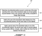
Fig. 3 is a flowchart illustrating steps of a method of manufacturing the downstream stator. -
Fig. 1 illustrates an aircraft engine depicted as agas turbine engine 10 of a type preferably provided for use in subsonic flight, generally comprising in serial flow communication afan 12 through which ambient air is propelled, acompressor section 14 for pressurizing the air, acombustor 16 in which the compressed air is mixed with fuel and ignited for generating an annular stream of hot combustion gases, and aturbine section 18 for extracting energy from the combustion gases. Thefan 12, thecompressor section 14, and theturbine section 18 are rotatable about acentral axis 11 of thegas turbine engine 10. In the embodiment shown, thegas turbine engine 10 comprises a high-pressure spool having a high-pressure shaft 20 drivingly engaging a high-pressure turbine 18A of theturbine section 18 to a high-pressure compressor 14A of thecompressor section 14, and a low-pressure spool having a low-pressure shaft 21 drivingly engaging a low-pressure orpower turbine 18B of theturbine section 18 to a low-pressure compressor 14B of thecompressor section 14 and drivingly engaged to thefan 12. - Although illustrated as a turbofan engine, the
gas turbine engine 10 may alternatively be another type of engine, for example a turboshaft engine, also generally comprising in serial flow communication a compressor section, a combustor, and a turbine section, and a fan through which ambient air is propelled. A turboprop engine may also apply. In addition, although theengine 10 is described herein for flight applications, it should be understood that other uses, such as industrial or the like, may apply. The engine may have one or more spools. - Still referring to
Fig. 1 , in the embodiment shown, a fan stator 23 is located within acore gaspath 24 of thegas turbine engine 10. The fan stator 23 is located downstream of thefan 12 relative to a flow within thecore gaspath 24. The low-pressure compressor 14B also referred to as a boost compressor, includes successive rows ofstators 14C androtors 14D. Afirst rotor 14D of the low-pressure compressor 14B may be located downstream of the fan stator 23 and upstream of afirst stator 14C of the low-pressure compressor 14B. Thefirst stator 14C may be the first stator the flow within thecore gaspath 24 meets after it leaves the fan stator 23. The fan stator 23 and the low-pressure compressor 14B are located within thecore gaspath 24, which is defined between aninner wall 25 and anouter wall 26. Thiscore gaspath 24 is located radially inwardly of an annular gaspath that extends around an engine core. Each of the core stator 23, and therotors 14D andstators 14C include airfoils extending through thecore gaspath 24. - For the remainder of the present disclosure, the fan stator 23 will be referred to as an
upstream stator 30 and thefirst stator 14C of the low-pressure compressor 14B will be referred to as adownstream stator 40. It will be understood that the principles of the present disclosure may apply to any combinations of two stators in serial flow communication with each other. These two stators may be located at any suitable locations along thecore gaspath 24. Any pair of stators may benefit from the present disclosure. - Referring now to
Fig. 2 , a front view of a section of thegas turbine engine 10 is presented and illustrates theupstream stator 30 in foreground and thedownstream stator 40 in background. Theupstream stator 30 includesupstream stator vanes 31 circumferentially distributed about thecentral axis 11. Theupstream stator vanes 31 extend in a direction having a radial component relative to thecentral axis 11 from theinner wall 25 to theouter wall 26. Thedownstream stator 40 hasdownstream stator vanes 41 circumferentially distributed about thecentral axis 11. Thedownstream stator vanes 41 extend in a direction having a radial component relative to the central axis from theinner wall 25 to theouter wall 26. For the sake of clarity, inFig. 2 , outlines of thedownstream stator vanes 41 are shown with dashed lines. Thedownstream stator 40 and itsdownstream stator vanes 41 are located rearward of theupstream stator 30 and theupstream stator vane 31. Thus, the airflow meets theupstream stator 30 before it meets thedownstream stator 40. - A number of the
upstream stator vanes 31 may be different (e.g., more, less) than a number of the downstream stator vanes 41. The number of theupstream stator vanes 31 may not be a multiple of the number of thedownstream stator vanes 41 and vice versa. Consequently, some of thedownstream stator vanes 41 may be exposed (e.g. visible) via spacing 32 defined between circumferentially adjacent upstream stator vanes 31. As shown inFig. 2 , some of thedownstream stator vanes 41 are visible through theupstream stator 30. In other words, some of thedownstream stator vanes 41 have areas exposed and visible via thespacing 32 defined between the upstream stator vanes 31. Because of the different numbers inupstream stator vanes 31 anddownstream stator vanes 41, some of thedownstream stator vanes 41 may be more susceptible to foreign object damage (FOD) because sensitive sections of thosedownstream stator vanes 41 may become exposed to FOD via thespacing 32 between the upstream stator vanes 31. InFig. 2 , thedownstream stator vanes 41 located at a plurality of circumferential positions, herein, at 1 o'clock, 3 o'clock, 5 o'clock, 7 o'clock, 9 o'clock, and 11 o'clock, may be most susceptible to FOD. Circumferential positions of thedownstream stator vanes 41 susceptible to FOD may vary as a function of a number of theupstream stator vanes 31 and as a function of a number of the downstream stator vanes 41. - The sensitive areas of the
downstream stator vanes 41 may correspond to leading edges of the downstream stator vanes 41. In some cases, the sensitive areas may correspond to the trailing edges. The thinner areas of the airfoils may correspond to the sensitive areas. More specifically, tip sections of the leading edges of thedownstream stator vanes 41 may be particularly prone to FOD. Herein, the expression tip sections may include a radially-outer 50% of a span of the downstream stator vanes 41. In some cases, the outer section of the span may include from 40% to 50% of the span. It may include all of the span in some cases. In some embodiments, base sections of thedownstream stator vanes 41 may be the sensitive areas; the base sections extending from 0% to 50% span from the radially-inner ends. In some cases, the tip sections includes a radially-outer 40%, or a radially-outer 30% in some cases, of the span. In some other cases, the tip sections includes a radially-outer 20% of the span. The tip sections of the leading edges of thedownstream stator vanes 41 may be more sensitive to FOD because thedownstream stator vanes 41 may decrease in both chord and thickness towards tips of the downstream stator vanes 41. This, in turn, may result in the tip sections of thedownstream stator vanes 41 less stiff than a remainder of thedownstream stator vanes 41 and, consequently, more susceptible to FOD. In some embodiments, the thickness distribution of the vane is constant along their spans. In the embodiment shown, the exposed part of the vanes is increasing from inner ends to outer ends. In this case, for the lower part, only small ice pellet may impact. For the higher part bigger ice pellets may impact. Small ice pellets may have less energy and may make less damage than bigger ice pellets closer to the tip. This may be engine-dependant. Some engine will fly at low speed and may be susceptible to FOD near the tip. Some other engine will fly much faster and may be susceptible to FOD closer to the radially inner ends of the vane. Small ice pellet at high speed might cause more damage than big pellets at low speed. - Still referring to
Fig. 2 , thedownstream stator vanes 41 may be divided in two groups: a first group including first vanes and a second group include at least a second vane. Major portions of leadingedges 41A of the first vanes may be circumferentially overlapped by the upstream stator vanes 31. That is, the major portions of the leading edges of the first vanes may be not visible when looking in a direction parallel to thecentral axis 11 and parallel to a direction of an air flow flowing through thegas turbine engine 10. The first vanes may be substantially shielded or protected against FOD by the upstream stator vanes 31. In other words, major portions of the first vanes may not be visible via thespacing 32 defined between the upstream stator vanes 31. In some embodiments, major portions of theleading edges 41A of the first vanes may not be visible via thespacing 32 defined between the upstream stator vanes 31. Herein, the expression "major portions" may include 50% or more of a span of the downstream stator vanes 41. In some embodiments, major portions include 80%, 90%, or 100% of the span of the vane. Major portions may include radially-outer 50% of the span. The major portions may include tip sections of the downstream stator vanes 41. The tip sections may include the outer 25% of the span of the downstream stator vanes 41. Since the first vanes of thedownstream stator vanes 41 have theirleading edges 41A substantially overlapped, and thus covered, by theupstream stator vanes 31, they may be less susceptible of being impacted by a foreign object. The first vanes of thedownstream stator vanes 41 are labelled with reference numeral 42 inFig. 2 . The at least second vane of thedownstream stator vanes 41 is exposed to FOD because a major portion of its leadingedges 41A is visible via thespacing 32 defined between the upstream stator vanes 31. The second vanes of thedownstream stator vanes 41 are labelled withreference numeral 43 inFig. 2 . - Still referring to
Fig. 2 , each of thedownstream stator vanes 41 may be thin at itsleading edge 41A and increase to a maximum thickness along a chord before tapering back down towards its trailingedge 41B. Adownstream stator vane 41 may be considered at risk of FOD if thedownstream stator vane 41 is exposed (e.g., visible within one of the spacing between two upstream stator vanes 31) anywhere along the chord from its leadingedge 41A to a location of maximum thickness. In other words, the major portions of the leading edges may correspond to leading edge sections extending along chords of thedownstream stator vanes 41 from the leadingedges 41A to locations of maximum thickness. The leading edge sections at spanwise locations closer to tips of thedownstream stator vanes 41, for instance at the tip sections of thedownstream stator vanes 41, may be more prone to FOD. Hence, thedownstream stator vanes 41 having their leading edge sections along their tip sections (e.g., outer 25% of their span) exposed within the spacing 32 may be susceptible to FOD and may be considered asecond vane 43. - The
downstream stator vanes 41 may have their trailingedges 41B visible via thespacing 32 between the upstream stator vanes 31. However, the trailingedges 41B, because they are not facing the incoming flow, may be less susceptible to FOD. Moreover, if a trailing edge of adownstream stator vane 41 is impacted, it may have less impact on overall aerodynamic performance of thedownstream stator 40 than if a leading edge were impacted. - In the embodiment shown, the first vanes 42 are made of a first material and the
second vanes 43 are made of a second material having a better ability to withstand impact without fracture than the first material. Any property of the second material, such as its stiffness, strength, or ductility may be increased to improve impact resistance. The first material may be aluminum and the second material may be steel. The stiffness, strength, and/or ductility of the second material may be at least about 10%, 15%, 20%, or 25% greater than that of the first material. The stiffness of the second material may be about two to three times that of the first material. The strength of the second material may be about from two to three times that of the first material. Herein, the expression "about" implies variations of plus or minus 10%. - As shown in
Fig. 2 , thedownstream stator 40 may include FOD zones Z1 circumferentially distributed about thecentral axis 11 where major portions of theleading edges 41A of the downstream stator vanes are visible via thespacing 32. The first vanes 42 may be located between or outside the FOD zones Z1 whereas thesecond vanes 43 may be located within the FOD zones Z1. In other words, thedownstream stator 40 may include FOD-free zones Z2 interspaced between the FOD zones Z1 and where there is a lesser risk of FOD. The first vanes 42 may be located within those FOD-free zones Z2. - The
downstream stator 40 may be a segmented ring including a plurality of segments circumferentially distributed about thecentral axis 11. The segments may includefirst segments 44 including one or more of the first vanes 42 andsecond segments 45 including one or more of thesecond vanes 43. Thefirst segments 44 may be located within the FOD-free zones Z2 whereas thesecond segments 45 may be located within the FOD zones Z1. Thefirst vane segments 44 may be interspaced between thesecond vane segments 45. - Referring now to
Fig. 3 , a method of manufacturing thedownstream stator 40 is shown at 300. Themethod 300 includes determining circumferential positions around thecentral axis 11 where thevanes 41 of thedownstream stator 40 are susceptible to foreign object damage via thespacing 32 defined between thevanes 31 of theupstream stator 30 at 302; installing the first vanes 42 of thedownstream stator 40 between the circumferential positions at 304, the first vanes 42 made of a first material; and installing thesecond vanes 43 of thedownstream stator 40 at the circumferential positions at 306, thesecond vanes 43 made of a second material having a stiffness greater than that of the first vanes 42. - In the present embodiment, the installing of the first vanes 42 includes installing the first vanes 42 made of aluminum and the installing of the
second vanes 43 includes installing thesecond vanes 43 made of steel. The installing of thesecond vanes 43 may include installing thesecond vanes 43 having the stiffness, strength, and/orductility 10%, 15%, 20%, or 25% greater than that of the first vanes 42. - In the embodiment shown, the installing of the
second vanes 43 at the circumferential positions including installing thesecond vane segments 45 at the circumferential positions where the vanes are susceptible to FOD. - More than two materials may be used. Combining the two materials may allow to minimize a weight of the downstream stator while minimizing impact on engine performance. This arrangement of two or more materials may prevent FOD while minimizing weight and costs.
- The embodiments described in this document provide non-limiting examples of possible implementations of the present technology. Upon review of the present disclosure, a person of ordinary skill in the art will recognize that changes may be made to the embodiments described herein without departing from the scope of the present technology. Yet further modifications could be implemented by a person of ordinary skill in the art in view of the present disclosure, which modifications would be within the scope of the present technology.
Claims (13)
- An aircraft engine (10), comprising:an upstream stator (30) having upstream stator vanes (31) circumferentially distributed about a central axis (11); anda downstream stator (40) having downstream stator vanes (41; 42, 43) circumferentially distributed about the central axis (11), the downstream stator (40) located downstream of the upstream stator (30) relative to an airflow flowing within a core gaspath of the aircraft engine (10), a number of the upstream stator vanes (31) being different than a number of the downstream stator vanes (41; 42, 43), the downstream stator vanes (41; 42, 43) including:a first vane (42) made of a first material, a major portion of a leading edge (41A) of the first vane (42) circumferentially overlapped by one of the upstream stator vanes (31), anda second vane (43) made of a second material having a greater stiffness, strength, and/or ductility than that of the first material, a major portion of a leading edge of the second vane (43) exposed via a spacing (32) defined between two of the upstream stator vanes (31).
- The aircraft engine of claim 1, wherein the major portion of the leading edge (41A) of the first vane (42) and/or the major portion of the leading edge of the second vane (43) include at least 50% of a span of the downstream stator vanes (41; 42, 43).
- The aircraft engine of claim 2, wherein the major portion is a radially-outer portion.
- The aircraft engine of any of the preceding claims, wherein the major portion includes a tip section.
- The aircraft engine of any of the preceding claims, wherein the first material is aluminum and the second material is steel.
- The aircraft engine of any of the preceding claims, comprising zones (Z1, Z2) circumferentially distributed about the central axis (11) where major portions of leading edges (41A) of the downstream stator vanes (41; 42, 43) are exposed via the spacing (32), the first vane (42) located between two of the zones (Z1, 2), the second vane (43) located within one of the zones (Z1; Z2).
- The aircraft engine of any of the preceding claims, wherein the stiffness of the second material is at least two times greater than that of the first material.
- The aircraft engine of any of the preceding claims, wherein the downstream stator (40) includes vane segments (44, 45) distributed about the central axis (11), each of the vane segments (44, 45) having one or more of the downstream stator vanes (41; 42, 43).
- The aircraft engine of claim 8, wherein the vane segments (44, 45) each include a first vane segment (44) including the first vane (42), and a second vane segment (45) including the second vane (43).
- A method of manufacturing a downstream stator (40) of a stator assembly, the stator assembly including an upstream stator (30) and the downstream stator (40) located downstream of the upstream stator (30), the method comprising:determining circumferential positions around a central axis (11) of the stator assembly where vanes (41; 42, 43) of the downstream stator (40) are at least partially exposed between vanes (31) of the upstream stator (30) thereby susceptible to foreign object damage;installing a first vane (42) of the downstream stator (40) between two of the circumferential positions, the first vane (42) made of a first material; andinstalling a second vane (43) of the downstream stator (40) at one of the circumferential positions, the second vane (43) made of a second material having a greater stiffness, strength, and/or ductility than that of the first material of the first vane (42).
- The method of claim 10, wherein the installing of the first vane (42) includes installing the first vane (42) made of aluminum, the installing of the second vane (43) includes installing the second vane (43) made of steel.
- The method of claim 10 or 11, wherein the installing of the second vane (43) includes installing the second vane (43) having the stiffness two times greater than that of the first vane (42).
- The method of any of claims 10 to 12, wherein the downstream stator (40) includes vane segments (44, 45) distributed about the central axis (11), each of the vane segments (44, 45) having one or more of the downstream stator vanes (41; 42, 43), the vane segments (44, 45) including a first vane segment (44) including the first vane (42) and a second vane segment (45) each including the second vane (43), the installing of the second vane (43) at the one of the circumferential positions including installing the second vane segment (45) at the one of the circumferential positions.
Applications Claiming Priority (1)
| Application Number | Priority Date | Filing Date | Title |
|---|---|---|---|
| US17/804,572 US11939886B2 (en) | 2022-05-30 | 2022-05-30 | Aircraft engine having stator vanes made of different materials |
Publications (2)
| Publication Number | Publication Date |
|---|---|
| EP4290050A1 true EP4290050A1 (en) | 2023-12-13 |
| EP4290050B1 EP4290050B1 (en) | 2025-03-12 |
Family
ID=86387012
Family Applications (1)
| Application Number | Title | Priority Date | Filing Date |
|---|---|---|---|
| EP23173772.7A Active EP4290050B1 (en) | 2022-05-30 | 2023-05-16 | Aircraft engine having downstream and upstream stator vanes of different numbers and made of different materials |
Country Status (3)
| Country | Link |
|---|---|
| US (1) | US11939886B2 (en) |
| EP (1) | EP4290050B1 (en) |
| CA (1) | CA3198398A1 (en) |
Citations (3)
| Publication number | Priority date | Publication date | Assignee | Title |
|---|---|---|---|---|
| US5984631A (en) * | 1995-07-14 | 1999-11-16 | Bmw Rolls-Royce Gmbh | Tandem turbine-blade cascade |
| US20120082553A1 (en) * | 2010-09-30 | 2012-04-05 | Andreas Eleftheriou | Metal encapsulated stator vane |
| US20140083103A1 (en) * | 2012-09-25 | 2014-03-27 | United Technologies Corporation | Gas turbine asymmetric nozzle guide vanes |
Family Cites Families (36)
| Publication number | Priority date | Publication date | Assignee | Title |
|---|---|---|---|---|
| US2798661A (en) | 1954-03-05 | 1957-07-09 | Westinghouse Electric Corp | Gas turbine power plant apparatus |
| US3830058A (en) * | 1973-02-26 | 1974-08-20 | Avco Corp | Fan engine mounting |
| GB2046849A (en) | 1979-04-17 | 1980-11-19 | Rolls Royse Ltd | Turbomachine strut |
| US4791783A (en) * | 1981-11-27 | 1988-12-20 | General Electric Company | Convertible aircraft engine |
| US5152661A (en) | 1988-05-27 | 1992-10-06 | Sheets Herman E | Method and apparatus for producing fluid pressure and controlling boundary layer |
| FR2738283B1 (en) * | 1995-08-30 | 1997-09-26 | Snecma | TURBOMACHINE ARRANGEMENT INCLUDING A VANE GRILLE AND AN INTERMEDIATE HOUSING |
| US6139259A (en) | 1998-10-29 | 2000-10-31 | General Electric Company | Low noise permeable airfoil |
| US7743497B2 (en) * | 2005-10-06 | 2010-06-29 | General Electric Company | Method of providing non-uniform stator vane spacing in a compressor |
| US8540490B2 (en) | 2008-06-20 | 2013-09-24 | General Electric Company | Noise reduction in a turbomachine, and a related method thereof |
| US8087253B2 (en) | 2008-11-20 | 2012-01-03 | General Electric Company | Methods, apparatus and systems concerning the circumferential clocking of turbine airfoils in relation to combustor cans and the flow of cooling air through the turbine hot gas flowpath |
| US8162603B2 (en) * | 2009-01-30 | 2012-04-24 | General Electric Company | Vane frame for a turbomachine and method of minimizing weight thereof |
| ITTO20110728A1 (en) | 2011-08-04 | 2013-02-05 | Avio Spa | STATIC PALLETED SEGMENT OF A GAS TURBINE FOR AERONAUTICAL MOTORS |
| JP5768642B2 (en) | 2011-10-04 | 2015-08-26 | 株式会社デンソー | Starter |
| ITTO20120517A1 (en) | 2012-06-14 | 2013-12-15 | Avio Spa | AERODYNAMIC PROFILE PLATE FOR A GAS TURBINE SYSTEM |
| WO2014055104A1 (en) | 2012-10-01 | 2014-04-10 | United Technologies Corporation | Gas turbine engine with first turbine vane clocking |
| EP2725193B1 (en) | 2012-10-24 | 2015-07-29 | MTU Aero Engines AG | Method for detuning the blades in a gas turbine engine and corresponding gas turbine engine. |
| US20140212284A1 (en) * | 2012-12-21 | 2014-07-31 | General Electric Company | Hybrid turbine nozzle |
| US9482237B1 (en) | 2013-03-26 | 2016-11-01 | Snecma | Method of designing a multi-stage turbomachine compressor |
| EP2986822B8 (en) * | 2013-04-16 | 2021-04-07 | Raytheon Technologies Corporation | Rotors with elastic modulus mistuned airfoils |
| US9605540B2 (en) * | 2013-08-20 | 2017-03-28 | Honeywell International Inc. | Alternating nozzles for radial inflow turbine |
| EP3047116B1 (en) | 2013-09-16 | 2021-04-14 | Raytheon Technologies Corporation | Variable area turbine vane row assembly |
| DE102013224081B4 (en) | 2013-11-26 | 2015-11-05 | Man Diesel & Turbo Se | compressor |
| US10400606B2 (en) * | 2014-01-15 | 2019-09-03 | United Technologies Corporation | Mistuned airfoil assemblies |
| US10094223B2 (en) | 2014-03-13 | 2018-10-09 | Pratt & Whitney Canada Corp. | Integrated strut and IGV configuration |
| US20160097281A1 (en) * | 2014-10-01 | 2016-04-07 | United Technologies Corporation | Gas turbine engine airfoil mistuning |
| US20160146040A1 (en) | 2014-11-25 | 2016-05-26 | United Technologies Corporation | Alternating Vane Asymmetry |
| US9845692B2 (en) * | 2015-05-05 | 2017-12-19 | General Electric Company | Turbine component connection with thermally stress-free fastener |
| BE1023290B1 (en) * | 2015-07-22 | 2017-01-24 | Safran Aero Boosters S.A. | AUBE COMPOSITE COMPRESSOR OF AXIAL TURBOMACHINE |
| US9909434B2 (en) | 2015-07-24 | 2018-03-06 | Pratt & Whitney Canada Corp. | Integrated strut-vane nozzle (ISV) with uneven vane axial chords |
| US10724540B2 (en) | 2016-12-06 | 2020-07-28 | Pratt & Whitney Canada Corp. | Stator for a gas turbine engine fan |
| US10526905B2 (en) * | 2017-03-29 | 2020-01-07 | United Technologies Corporation | Asymmetric vane assembly |
| JP7017446B2 (en) * | 2018-03-20 | 2022-02-08 | 本田技研工業株式会社 | Axial flow compressor |
| DE102018119704A1 (en) | 2018-08-14 | 2020-02-20 | Rolls-Royce Deutschland Ltd & Co Kg | Paddle wheel of a turbomachine |
| GB201903466D0 (en) | 2019-03-14 | 2019-05-01 | Rolls Royce Plc | Core duct assembly |
| GB202018264D0 (en) | 2020-11-20 | 2021-01-06 | Rolls Royce Plc | Gas turbine engine with improved vigv shielding |
| FR3116861B1 (en) * | 2020-11-27 | 2022-10-21 | Safran Aircraft Engines | DEVICE AND METHOD FOR CONTROLLING THE SECTORS FOR THE ASSEMBLY OF DISTRIBUTORS OF A TURBINE |
-
2022
- 2022-05-30 US US17/804,572 patent/US11939886B2/en active Active
-
2023
- 2023-05-02 CA CA3198398A patent/CA3198398A1/en active Pending
- 2023-05-16 EP EP23173772.7A patent/EP4290050B1/en active Active
Patent Citations (3)
| Publication number | Priority date | Publication date | Assignee | Title |
|---|---|---|---|---|
| US5984631A (en) * | 1995-07-14 | 1999-11-16 | Bmw Rolls-Royce Gmbh | Tandem turbine-blade cascade |
| US20120082553A1 (en) * | 2010-09-30 | 2012-04-05 | Andreas Eleftheriou | Metal encapsulated stator vane |
| US20140083103A1 (en) * | 2012-09-25 | 2014-03-27 | United Technologies Corporation | Gas turbine asymmetric nozzle guide vanes |
Also Published As
| Publication number | Publication date |
|---|---|
| US11939886B2 (en) | 2024-03-26 |
| CA3198398A1 (en) | 2023-11-30 |
| EP4290050B1 (en) | 2025-03-12 |
| US20230383660A1 (en) | 2023-11-30 |
Similar Documents
| Publication | Publication Date | Title |
|---|---|---|
| US10436035B1 (en) | Fan design | |
| EP3369891B1 (en) | Gas turbine engine vanes | |
| US12320274B2 (en) | Compressor stator with leading edge fillet | |
| CA2884014C (en) | Integrated strut and igv configuration | |
| EP2204534B1 (en) | Turbine airfoil clocking | |
| EP2943653B1 (en) | Rotor blade and corresponding gas turbine engine | |
| US20100054929A1 (en) | Turbine airfoil clocking | |
| US10683806B2 (en) | Protected core inlet with reduced capture area | |
| US20250020064A1 (en) | Test blade for gas turbine engine and method of making | |
| US11939886B2 (en) | Aircraft engine having stator vanes made of different materials | |
| EP4286648A1 (en) | Aircraft engine with vane row having vanes with differing pitch | |
| US12091178B2 (en) | Aircraft engine with stator having varying geometry | |
| US11268386B2 (en) | Gas turbine engine having optimized fan | |
| US11415012B1 (en) | Tandem stator with depressions in gaspath wall | |
| EP4144959A1 (en) | Fluid machine for an aircraft engine and aircraft engine |
Legal Events
| Date | Code | Title | Description |
|---|---|---|---|
| PUAI | Public reference made under article 153(3) epc to a published international application that has entered the european phase |
Free format text: ORIGINAL CODE: 0009012 |
|
| STAA | Information on the status of an ep patent application or granted ep patent |
Free format text: STATUS: THE APPLICATION HAS BEEN PUBLISHED |
|
| AK | Designated contracting states |
Kind code of ref document: A1 Designated state(s): AL AT BE BG CH CY CZ DE DK EE ES FI FR GB GR HR HU IE IS IT LI LT LU LV MC ME MK MT NL NO PL PT RO RS SE SI SK SM TR |
|
| STAA | Information on the status of an ep patent application or granted ep patent |
Free format text: STATUS: REQUEST FOR EXAMINATION WAS MADE |
|
| 17P | Request for examination filed |
Effective date: 20240604 |
|
| RBV | Designated contracting states (corrected) |
Designated state(s): AL AT BE BG CH CY CZ DE DK EE ES FI FR GB GR HR HU IE IS IT LI LT LU LV MC ME MK MT NL NO PL PT RO RS SE SI SK SM TR |
|
| GRAP | Despatch of communication of intention to grant a patent |
Free format text: ORIGINAL CODE: EPIDOSNIGR1 |
|
| STAA | Information on the status of an ep patent application or granted ep patent |
Free format text: STATUS: GRANT OF PATENT IS INTENDED |
|
| INTG | Intention to grant announced |
Effective date: 20241008 |
|
| GRAS | Grant fee paid |
Free format text: ORIGINAL CODE: EPIDOSNIGR3 |
|
| GRAA | (expected) grant |
Free format text: ORIGINAL CODE: 0009210 |
|
| STAA | Information on the status of an ep patent application or granted ep patent |
Free format text: STATUS: THE PATENT HAS BEEN GRANTED |
|
| AK | Designated contracting states |
Kind code of ref document: B1 Designated state(s): AL AT BE BG CH CY CZ DE DK EE ES FI FR GB GR HR HU IE IS IT LI LT LU LV MC ME MK MT NL NO PL PT RO RS SE SI SK SM TR |
|
| REG | Reference to a national code |
Ref country code: GB Ref legal event code: FG4D |
|
| REG | Reference to a national code |
Ref country code: CH Ref legal event code: EP |
|
| REG | Reference to a national code |
Ref country code: DE Ref legal event code: R096 Ref document number: 602023002356 Country of ref document: DE |
|
| REG | Reference to a national code |
Ref country code: IE Ref legal event code: FG4D |
|
| PG25 | Lapsed in a contracting state [announced via postgrant information from national office to epo] |
Ref country code: RS Free format text: LAPSE BECAUSE OF FAILURE TO SUBMIT A TRANSLATION OF THE DESCRIPTION OR TO PAY THE FEE WITHIN THE PRESCRIBED TIME-LIMIT Effective date: 20250612 |
|
| PG25 | Lapsed in a contracting state [announced via postgrant information from national office to epo] |
Ref country code: FI Free format text: LAPSE BECAUSE OF FAILURE TO SUBMIT A TRANSLATION OF THE DESCRIPTION OR TO PAY THE FEE WITHIN THE PRESCRIBED TIME-LIMIT Effective date: 20250312 |
|
| PG25 | Lapsed in a contracting state [announced via postgrant information from national office to epo] |
Ref country code: ES Free format text: LAPSE BECAUSE OF FAILURE TO SUBMIT A TRANSLATION OF THE DESCRIPTION OR TO PAY THE FEE WITHIN THE PRESCRIBED TIME-LIMIT Effective date: 20250312 |
|
| REG | Reference to a national code |
Ref country code: LT Ref legal event code: MG9D |
|
| PG25 | Lapsed in a contracting state [announced via postgrant information from national office to epo] |
Ref country code: NO Free format text: LAPSE BECAUSE OF FAILURE TO SUBMIT A TRANSLATION OF THE DESCRIPTION OR TO PAY THE FEE WITHIN THE PRESCRIBED TIME-LIMIT Effective date: 20250612 |
|
| PG25 | Lapsed in a contracting state [announced via postgrant information from national office to epo] |
Ref country code: HR Free format text: LAPSE BECAUSE OF FAILURE TO SUBMIT A TRANSLATION OF THE DESCRIPTION OR TO PAY THE FEE WITHIN THE PRESCRIBED TIME-LIMIT Effective date: 20250312 |
|
| REG | Reference to a national code |
Ref country code: NL Ref legal event code: MP Effective date: 20250312 |
|
| PG25 | Lapsed in a contracting state [announced via postgrant information from national office to epo] |
Ref country code: LV Free format text: LAPSE BECAUSE OF FAILURE TO SUBMIT A TRANSLATION OF THE DESCRIPTION OR TO PAY THE FEE WITHIN THE PRESCRIBED TIME-LIMIT Effective date: 20250312 |
|
| PG25 | Lapsed in a contracting state [announced via postgrant information from national office to epo] |
Ref country code: GR Free format text: LAPSE BECAUSE OF FAILURE TO SUBMIT A TRANSLATION OF THE DESCRIPTION OR TO PAY THE FEE WITHIN THE PRESCRIBED TIME-LIMIT Effective date: 20250613 Ref country code: BG Free format text: LAPSE BECAUSE OF FAILURE TO SUBMIT A TRANSLATION OF THE DESCRIPTION OR TO PAY THE FEE WITHIN THE PRESCRIBED TIME-LIMIT Effective date: 20250312 |
|
| REG | Reference to a national code |
Ref country code: AT Ref legal event code: MK05 Ref document number: 1775149 Country of ref document: AT Kind code of ref document: T Effective date: 20250312 |
|
| PG25 | Lapsed in a contracting state [announced via postgrant information from national office to epo] |
Ref country code: NL Free format text: LAPSE BECAUSE OF FAILURE TO SUBMIT A TRANSLATION OF THE DESCRIPTION OR TO PAY THE FEE WITHIN THE PRESCRIBED TIME-LIMIT Effective date: 20250312 |
|
| PG25 | Lapsed in a contracting state [announced via postgrant information from national office to epo] |
Ref country code: SE Free format text: LAPSE BECAUSE OF FAILURE TO SUBMIT A TRANSLATION OF THE DESCRIPTION OR TO PAY THE FEE WITHIN THE PRESCRIBED TIME-LIMIT Effective date: 20250312 |
|
| PG25 | Lapsed in a contracting state [announced via postgrant information from national office to epo] |
Ref country code: SM Free format text: LAPSE BECAUSE OF FAILURE TO SUBMIT A TRANSLATION OF THE DESCRIPTION OR TO PAY THE FEE WITHIN THE PRESCRIBED TIME-LIMIT Effective date: 20250312 |
|
| PG25 | Lapsed in a contracting state [announced via postgrant information from national office to epo] |
Ref country code: PT Free format text: LAPSE BECAUSE OF FAILURE TO SUBMIT A TRANSLATION OF THE DESCRIPTION OR TO PAY THE FEE WITHIN THE PRESCRIBED TIME-LIMIT Effective date: 20250714 |
|
| PG25 | Lapsed in a contracting state [announced via postgrant information from national office to epo] |
Ref country code: PL Free format text: LAPSE BECAUSE OF FAILURE TO SUBMIT A TRANSLATION OF THE DESCRIPTION OR TO PAY THE FEE WITHIN THE PRESCRIBED TIME-LIMIT Effective date: 20250312 Ref country code: IT Free format text: LAPSE BECAUSE OF FAILURE TO SUBMIT A TRANSLATION OF THE DESCRIPTION OR TO PAY THE FEE WITHIN THE PRESCRIBED TIME-LIMIT Effective date: 20250312 |
|
| PG25 | Lapsed in a contracting state [announced via postgrant information from national office to epo] |
Ref country code: AT Free format text: LAPSE BECAUSE OF FAILURE TO SUBMIT A TRANSLATION OF THE DESCRIPTION OR TO PAY THE FEE WITHIN THE PRESCRIBED TIME-LIMIT Effective date: 20250312 |
|
| PG25 | Lapsed in a contracting state [announced via postgrant information from national office to epo] |
Ref country code: CZ Free format text: LAPSE BECAUSE OF FAILURE TO SUBMIT A TRANSLATION OF THE DESCRIPTION OR TO PAY THE FEE WITHIN THE PRESCRIBED TIME-LIMIT Effective date: 20250312 Ref country code: EE Free format text: LAPSE BECAUSE OF FAILURE TO SUBMIT A TRANSLATION OF THE DESCRIPTION OR TO PAY THE FEE WITHIN THE PRESCRIBED TIME-LIMIT Effective date: 20250312 |
|
| PG25 | Lapsed in a contracting state [announced via postgrant information from national office to epo] |
Ref country code: RO Free format text: LAPSE BECAUSE OF FAILURE TO SUBMIT A TRANSLATION OF THE DESCRIPTION OR TO PAY THE FEE WITHIN THE PRESCRIBED TIME-LIMIT Effective date: 20250312 |
|
| PG25 | Lapsed in a contracting state [announced via postgrant information from national office to epo] |
Ref country code: SK Free format text: LAPSE BECAUSE OF FAILURE TO SUBMIT A TRANSLATION OF THE DESCRIPTION OR TO PAY THE FEE WITHIN THE PRESCRIBED TIME-LIMIT Effective date: 20250312 |
|
| PG25 | Lapsed in a contracting state [announced via postgrant information from national office to epo] |
Ref country code: IS Free format text: LAPSE BECAUSE OF FAILURE TO SUBMIT A TRANSLATION OF THE DESCRIPTION OR TO PAY THE FEE WITHIN THE PRESCRIBED TIME-LIMIT Effective date: 20250712 |
|
| REG | Reference to a national code |
Ref country code: DE Ref legal event code: R097 Ref document number: 602023002356 Country of ref document: DE |
|
| PG25 | Lapsed in a contracting state [announced via postgrant information from national office to epo] |
Ref country code: DK Free format text: LAPSE BECAUSE OF FAILURE TO SUBMIT A TRANSLATION OF THE DESCRIPTION OR TO PAY THE FEE WITHIN THE PRESCRIBED TIME-LIMIT Effective date: 20250312 |
|
| PG25 | Lapsed in a contracting state [announced via postgrant information from national office to epo] |
Ref country code: LU Free format text: LAPSE BECAUSE OF NON-PAYMENT OF DUE FEES Effective date: 20250516 |
|
| PLBE | No opposition filed within time limit |
Free format text: ORIGINAL CODE: 0009261 |
|
| STAA | Information on the status of an ep patent application or granted ep patent |
Free format text: STATUS: NO OPPOSITION FILED WITHIN TIME LIMIT |
|
| REG | Reference to a national code |
Ref country code: CH Ref legal event code: L10 Free format text: ST27 STATUS EVENT CODE: U-0-0-L10-L00 (AS PROVIDED BY THE NATIONAL OFFICE) Effective date: 20260121 |
|
| REG | Reference to a national code |
Ref country code: BE Ref legal event code: MM Effective date: 20250531 |
|
| PG25 | Lapsed in a contracting state [announced via postgrant information from national office to epo] |
Ref country code: MC Free format text: LAPSE BECAUSE OF FAILURE TO SUBMIT A TRANSLATION OF THE DESCRIPTION OR TO PAY THE FEE WITHIN THE PRESCRIBED TIME-LIMIT Effective date: 20250312 |
|
| 26N | No opposition filed |
Effective date: 20251215 |
|
| PG25 | Lapsed in a contracting state [announced via postgrant information from national office to epo] |
Ref country code: IE Free format text: LAPSE BECAUSE OF NON-PAYMENT OF DUE FEES Effective date: 20250516 |
|
| PG25 | Lapsed in a contracting state [announced via postgrant information from national office to epo] |
Ref country code: BE Free format text: LAPSE BECAUSE OF NON-PAYMENT OF DUE FEES Effective date: 20250531 |
|
| PG25 | Lapsed in a contracting state [announced via postgrant information from national office to epo] |
Ref country code: LT Free format text: LAPSE BECAUSE OF FAILURE TO SUBMIT A TRANSLATION OF THE DESCRIPTION OR TO PAY THE FEE WITHIN THE PRESCRIBED TIME-LIMIT Effective date: 20250312 |
|
| PGFP | Annual fee paid to national office [announced via postgrant information from national office to epo] |
Ref country code: DE Payment date: 20260421 Year of fee payment: 4 |
|
| PGFP | Annual fee paid to national office [announced via postgrant information from national office to epo] |
Ref country code: FR Payment date: 20260421 Year of fee payment: 4 |
|
| PG25 | Lapsed in a contracting state [announced via postgrant information from national office to epo] |
Ref country code: CY Free format text: LAPSE BECAUSE OF FAILURE TO SUBMIT A TRANSLATION OF THE DESCRIPTION OR TO PAY THE FEE WITHIN THE PRESCRIBED TIME-LIMIT Effective date: 20250312 |