EP4290020A1 - System, method, and work vehicle - Google Patents
System, method, and work vehicle Download PDFInfo
- Publication number
- EP4290020A1 EP4290020A1 EP22779690.1A EP22779690A EP4290020A1 EP 4290020 A1 EP4290020 A1 EP 4290020A1 EP 22779690 A EP22779690 A EP 22779690A EP 4290020 A1 EP4290020 A1 EP 4290020A1
- Authority
- EP
- European Patent Office
- Prior art keywords
- vehicle
- route
- restriction condition
- track
- search
- Prior art date
- Legal status (The legal status is an assumption and is not a legal conclusion. Google has not performed a legal analysis and makes no representation as to the accuracy of the status listed.)
- Granted
Links
Images




Classifications
-
- G—PHYSICS
- G05—CONTROLLING; REGULATING
- G05D—SYSTEMS FOR CONTROLLING OR REGULATING NON-ELECTRIC VARIABLES
- G05D1/00—Control of position, course, altitude or attitude of land, water, air or space vehicles, e.g. using automatic pilots
- G05D1/20—Control system inputs
- G05D1/22—Command input arrangements
- G05D1/229—Command input data, e.g. waypoints
- G05D1/2295—Command input data, e.g. waypoints defining restricted zones, e.g. no-flight zones or geofences
-
- E—FIXED CONSTRUCTIONS
- E02—HYDRAULIC ENGINEERING; FOUNDATIONS; SOIL SHIFTING
- E02F—DREDGING; SOIL-SHIFTING
- E02F9/00—Component parts of dredgers or soil-shifting machines, not restricted to one of the kinds covered by groups E02F3/00 - E02F7/00
- E02F9/20—Drives; Control devices
- E02F9/2025—Particular purposes of control systems not otherwise provided for
- E02F9/205—Remotely operated machines, e.g. unmanned vehicles
-
- E—FIXED CONSTRUCTIONS
- E02—HYDRAULIC ENGINEERING; FOUNDATIONS; SOIL SHIFTING
- E02F—DREDGING; SOIL-SHIFTING
- E02F9/00—Component parts of dredgers or soil-shifting machines, not restricted to one of the kinds covered by groups E02F3/00 - E02F7/00
- E02F9/26—Indicating devices
- E02F9/261—Surveying the work-site to be treated
- E02F9/262—Surveying the work-site to be treated with follow-up actions to control the work tool, e.g. controller
-
- G—PHYSICS
- G01—MEASURING; TESTING
- G01C—MEASURING DISTANCES, LEVELS OR BEARINGS; SURVEYING; NAVIGATION; GYROSCOPIC INSTRUMENTS; PHOTOGRAMMETRY OR VIDEOGRAMMETRY
- G01C21/00—Navigation; Navigational instruments not provided for in groups G01C1/00 - G01C19/00
- G01C21/26—Navigation; Navigational instruments not provided for in groups G01C1/00 - G01C19/00 specially adapted for navigation in a road network
- G01C21/34—Route searching; Route guidance
- G01C21/3446—Details of route searching algorithms, e.g. Dijkstra, A*, arc-flags or using precalculated routes
-
- G—PHYSICS
- G05—CONTROLLING; REGULATING
- G05D—SYSTEMS FOR CONTROLLING OR REGULATING NON-ELECTRIC VARIABLES
- G05D1/00—Control of position, course, altitude or attitude of land, water, air or space vehicles, e.g. using automatic pilots
- G05D1/20—Control system inputs
- G05D1/24—Arrangements for determining position or orientation
- G05D1/246—Arrangements for determining position or orientation using environment maps, e.g. simultaneous localisation and mapping [SLAM]
- G05D1/2464—Arrangements for determining position or orientation using environment maps, e.g. simultaneous localisation and mapping [SLAM] using an occupancy grid
-
- G—PHYSICS
- G05—CONTROLLING; REGULATING
- G05D—SYSTEMS FOR CONTROLLING OR REGULATING NON-ELECTRIC VARIABLES
- G05D1/00—Control of position, course, altitude or attitude of land, water, air or space vehicles, e.g. using automatic pilots
- G05D1/60—Intended control result
- G05D1/617—Safety or protection, e.g. defining protection zones around obstacles or avoiding hazards
- G05D1/622—Obstacle avoidance
-
- G—PHYSICS
- G05—CONTROLLING; REGULATING
- G05D—SYSTEMS FOR CONTROLLING OR REGULATING NON-ELECTRIC VARIABLES
- G05D1/00—Control of position, course, altitude or attitude of land, water, air or space vehicles, e.g. using automatic pilots
- G05D1/60—Intended control result
- G05D1/644—Optimisation of travel parameters, e.g. of energy consumption, journey time or distance
-
- G—PHYSICS
- G05—CONTROLLING; REGULATING
- G05D—SYSTEMS FOR CONTROLLING OR REGULATING NON-ELECTRIC VARIABLES
- G05D2105/00—Specific applications of the controlled vehicles
- G05D2105/05—Specific applications of the controlled vehicles for soil shifting, building, civil engineering or mining, e.g. excavators
-
- G—PHYSICS
- G05—CONTROLLING; REGULATING
- G05D—SYSTEMS FOR CONTROLLING OR REGULATING NON-ELECTRIC VARIABLES
- G05D2107/00—Specific environments of the controlled vehicles
- G05D2107/20—Land use
-
- G—PHYSICS
- G05—CONTROLLING; REGULATING
- G05D—SYSTEMS FOR CONTROLLING OR REGULATING NON-ELECTRIC VARIABLES
- G05D2107/00—Specific environments of the controlled vehicles
- G05D2107/70—Industrial sites, e.g. warehouses or factories
- G05D2107/73—Mining
-
- G—PHYSICS
- G05—CONTROLLING; REGULATING
- G05D—SYSTEMS FOR CONTROLLING OR REGULATING NON-ELECTRIC VARIABLES
- G05D2109/00—Types of controlled vehicles
- G05D2109/10—Land vehicles
-
- Y—GENERAL TAGGING OF NEW TECHNOLOGICAL DEVELOPMENTS; GENERAL TAGGING OF CROSS-SECTIONAL TECHNOLOGIES SPANNING OVER SEVERAL SECTIONS OF THE IPC; TECHNICAL SUBJECTS COVERED BY FORMER USPC CROSS-REFERENCE ART COLLECTIONS [XRACs] AND DIGESTS
- Y02—TECHNOLOGIES OR APPLICATIONS FOR MITIGATION OR ADAPTATION AGAINST CLIMATE CHANGE
- Y02T—CLIMATE CHANGE MITIGATION TECHNOLOGIES RELATED TO TRANSPORTATION
- Y02T10/00—Road transport of goods or passengers
- Y02T10/10—Internal combustion engine [ICE] based vehicles
- Y02T10/40—Engine management systems
Definitions
- the present disclosure relates to a system, a method, and a work vehicle.
- Patent Document 1 discloses a technique related to a method of generating a traveling route of an unmanned vehicle.
- Patent Document 1 Japanese Unexamined Patent Application, First Publication No. 2010-073080
- Track calculation for a vehicle to travel automatically is an optimization problem. Additionally, in the track calculation, an obstacle present at a work site is given as a restriction condition.
- a mathematical model used to search for a track is represented by multi-dimensional vectors such as a position, posture, steering angle, speed, and acceleration of a vehicle, and a position and shape of obstacles are not necessarily simple, and nonlinearity of the restriction condition may be high. For this reason, it is difficult to calculate a traveling track of the vehicle on-line because the calculation of the track increases an amount of calculation or converges to a local solution. Meanwhile, when the number of dimensions of a model is reduced in order to reduce the amount of calculation, there is a possibility that operations related to the reduced dimensions may be discontinuous in an obtained track.
- An object of the present disclosure is to provide a track search device and a track search method capable of obtaining a continuous track with a small amount of calculation.
- a system searching for a track for a vehicle to travel automatically includes a processor.
- the processor includes a route search unit configured to search for a series having elements of a position and posture of the vehicle, which is a route for moving from an initial position to a target position of the vehicle, based on a first restriction condition representing a position of an obstacle, a restriction condition generation unit configured to generate a second restriction condition in which a penalty value increases according to a deviation distance from the route, and a track search unit configured to search for a series having elements of a position, posture, speed, and steering angle of the vehicle, which is a track for moving from the initial position to the target position of the vehicle, based on the second restriction condition.
- a method of searching for a track for a vehicle to travel automatically includes the following processes.
- a series having elements of a position and posture of the vehicle which is a route for moving from an initial position to a target position of the vehicle, is searched for based on a first restriction condition representing a position of an obstacle.
- a second restriction condition is generated, in which a penalty value increases according to a deviation distance from the route.
- a series having elements of a position, posture, speed, and steering angle of the vehicle which is a track for moving from the initial position to the target position of the vehicle, is searched for based on the second restriction condition.
- a work vehicle including: a vehicle body; a traveling device for causing the vehicle body to travel; and a processor.
- the processor includes a route search unit configured to search for a series having elements of a position and posture of the work vehicle, which is a route for moving from an initial position to a target position of the work vehicle, based on a first restriction condition representing a position of an obstacle, a restriction condition generation unit configured to generate a second restriction condition in which a penalty value increases according to a deviation distance from the route, a track search unit configured to search for a series having elements of a position, posture, speed, and steering angle of the work vehicle, which is a track for moving from the initial position to the target position of the work vehicle, based on the second restriction condition, and a traveling control unit configured to control the traveling device according to the track.
- the track search device can obtain a continuous track with a small amount of calculation.
- FIG. 1 is a side view of a work vehicle according to a first embodiment.
- a work vehicle 100 according to the first embodiment is a wheel loader.
- the work vehicle 100 is driven by automatic operation. That is, the work vehicle 100 is an unmanned traveling vehicle.
- the work vehicle 100 includes a vehicle body 110, work equipment 120, and a control device 140.
- the vehicle body 110 includes a front vehicle body 111, a rear vehicle body 112, and a steering actuator 113.
- the front vehicle body 111 and the rear vehicle body 112 are rotatably attached around a steering shaft extending in a vertical direction of the vehicle body 110.
- a pair of front wheels WF is provided at a lower portion of the front vehicle body 111.
- a pair of rear wheels WR is provided at a lower portion of the rear vehicle body 112.
- the rear vehicle body 112 includes a power source 1121 and a power transmission device 1122.
- the power source 1121 is, for example, a diesel engine.
- the power transmission device 1122 shifts a speed of a driving force input to an input shaft, and outputs the speed from the output shaft.
- the output shaft of the power transmission device 1122 is connected to the front wheel WF via a front axle (not shown) and is connected to the rear wheel WR via a rear axle (not shown).
- the front axle supports the front vehicle body 111 to be able to travel.
- the rear axle supports the rear vehicle body 112 so as to be able to travel.
- the front axle and the rear axle are provided with braking devices (not shown).
- the power transmission device 1122 is provided with a rotation sensor 1123.
- the rotation sensor 1123 measures a rotation speed of the output shaft of the power transmission device 1122.
- the control device 140 can specify the speed and the acceleration of the work vehicle 100 based on measurement data of the rotation sensor 1123.
- a detection device 1124 and a positioning device 1125 are provided on the upper portion of the rear vehicle body 112.
- the detection device 1124 detects a three-dimensional position of an object present around the work vehicle 100.
- a Light Detection and Ranging (LiDar), a stereo camera, an ultra wide band (UWB) distance measuring device, and the like are exemplary examples of the detection device 1124.
- the detection device 1124 is provided, for example, such that a detection direction faces the front.
- the positioning device 1125 measures a position and a posture (posture angle) of the work vehicle 100 in global coordinates by a Global Navigation Satellite System (GNSS) or the like.
- the position is represented by, for example, latitude and longitude.
- the posture is represented by, for example, an azimuth angle of the rear vehicle body 112 with the north as a reference azimuth.
- the position and posture of the work vehicle 100 will also be referred to as a pose of the work vehicle 100.
- the steering actuator 113 is, for example, a hydraulic cylinder. A proximal end portion of the steering actuator 113 is attached to the rear vehicle body 112, and a distal end portion thereof is attached to the front vehicle body 111.
- the steering actuator 113 expands and contracts by hydraulic oil to define an angle formed between the front vehicle body 111 and the rear vehicle body 112. That is, the expansion and contraction of the steering actuator 113 defines the steering angle of the front wheels WF.
- the steering actuator 113 is provided with a stroke sensor 1131 that measures a stroke length of the steering actuator 113.
- the control device 140 can specify the steering angle of the work vehicle 100 based on the measurement data of the stroke sensor 1131.
- the power transmission device 1122, the braking device, and the steering actuator 113 are traveling devices for causing the vehicle body 110 to travel.
- the work equipment 120 is used for excavating and transporting a work object such as earth.
- the work equipment 120 is provided in a front part of the vehicle body 110.
- the control device 140 causes the work vehicle 100 to travel based on the detection data of the detection device 1124.
- FIG. 2 is a schematic block diagram showing a configuration of the control device 140 according to the first embodiment.
- the control device 140 is a computer including a processor 210, a main memory 230, a storage 250, and an interface 270.
- the storage 250 is a non-transitory, tangible storage medium.
- a magnetic disk, an optical disk, a magneto-optical disk, a semiconductor memory, and the like are exemplary examples of the storage 250.
- the storage 250 may be an internal medium directly connected to the bus of the control device 140, or an external medium connected to the control device 140 via the interface 270 or a communication line.
- the storage 250 stores a program for controlling the work vehicle 100.
- the program may be for realizing some of functions exerted by the control device 140.
- the program may exert functions in combination with other programs already stored in the storage 250 or in combination with other programs mounted on other devices.
- the control device 140 may include a custom Large Scale Integrated Circuit (LSI) such as a Programmable Logic Device (PLD) in addition to or in place of the above configuration.
- LSI Large Scale Integrated Circuit
- PLD Programmable Logic Device
- PAL Programmable Array Logic
- GAL Generic Array Logic
- CPLD Complex Programmable Logic Device
- FPGA Field Programmable Gate Array
- some or all of the functions realized by the processor may be realized by the integrated circuit.
- the processor 210 includes an acquisition unit 211, a map generation unit 213, a target determination unit 212, a route search unit 214, a restriction condition generation unit 215, a track search unit 216, and a traveling control unit 217 by executing a program.
- the control device 140 is an example of a track search device.
- the acquisition unit 211 acquires the measurement data of the stroke sensor 1131, the rotation sensor 1123, the detection device 1124, and the positioning device 1125. Accordingly, the acquisition unit 211 specifies the position, the posture angle, the steering angle, the speed, and the acceleration of the work vehicle 100, and the position of an obstacle present around the work vehicle 100.
- the map generation unit 213 generates map data representing the periphery of the work vehicle 100 by using the measurement data of the detection device 1124 acquired by the acquisition unit 211, and the measurement data of the positioning device 1125.
- the map generation unit 213 generates map data by using, for example, Simultaneous Localization and Mapping (SLAM) technology.
- the map data is represented by, for example, an occupied grid map related to a global coordinate system.
- FIG. 3 is a diagram showing an example of the map data according to the first embodiment.
- a score representing the distance from the obstacle is attached to each grid of the map data. A score of a grid representing a position where the obstacle exists is zero, and the farther the distance from the obstacle is, the higher the score.
- the score is represented by, for example, a Manhattan distance from the closest obstacle.
- the map generation unit 213 moves the position of the obstacle indicated by the measurement data of the detection device 1124 in parallel based on the position indicated by the measurement data of the positioning device 1125, and the position of the obstacle in the global coordinate system can be specified by the rotation based on the posture angle.
- the map data generated by the map generation unit 213 is recorded in the main memory 230.
- the target determination unit 212 determines a target pose (target position) of the work vehicle 100. For example, the target determination unit 212 determines a position of a loading site designated in advance and a posture angle facing the loading site to the target pose in a case where the earth is not held by the work equipment 120. Further, the target determination unit 212 determines a position of a release site designated in advance and a posture angle facing the release site as the target pose in a case where the earth is held by the work equipment 120. At this time, for example, the target determination unit 212 may correct the positions of the loading site and the release site based on the map data.
- the route search unit 214 searches for a route connecting a current pose (initial position) of the work vehicle 100 acquired by the acquisition unit 211 to a target pose determined by a target determination unit 212.
- the "route" is represented by an ordinal set of poses. That is, the route obtained by the route search unit 214 is a series of the position and the posture angle of the work vehicle 100.
- the route search unit 214 searches for a route by using a complete search algorithm (first search algorithm) such as a dynamic planning method.
- the Dixstra method, the hybrid A*, and the like are exemplary examples of the algorithm related to the dynamic planning method.
- a heuristic cost can be obtained by a Reeds Shepp method or a Laplace Potential method.
- the Reeds Shepp method is a method for finding a shortest route of a non-holonomic system when an obstacle or the continuity of curvature is ignored.
- the Laplace Potential method is a method for obtaining the shortest route when a non-holonomic restriction is ignored.
- the restriction condition (first restriction condition) for the search by the route search unit 214 is that the map generation unit 213 does not contact the obstacle represented by the generated map data, that the pose at an end point matches the target pose, and the steering angle is within a predetermined movable range.
- the evaluation function of the search by the route search unit 214 is a function whose value decreases as the travel distance becomes shorter.
- the model used for the search by the route search unit 214 is represented by Equation (1).
- x ⁇ k + 1 ⁇ y k + 1 ⁇ k + 1 x k + L tan ⁇ k sin ⁇ k + ⁇ t ⁇ k tan ⁇ k L ⁇ sin ⁇ k y k + L tan ⁇ k ⁇ cos ⁇ k + ⁇ t ⁇ k tan ⁇ k L + cos ⁇ k ⁇ k + ⁇ t ⁇ k tan ⁇ k L
- x[k] indicates an x-coordinate (for example, latitude) at time k.
- y[k] indicates a y-coordinate (for example, longitude) at time k.
- ⁇ [k] indicates a posture angle at time k.
- ⁇ [k] indicates a steering angle at time k.
- v[k] indicates a speed at time k.
- k+1 represents a time after a unit time of time k.
- ⁇ t indicates a time step width.
- L indicates a length from an articulate center to the front wheel WF. That is, a mathematical model used by the route search unit 214 is a model of three elements of the x-coordinate, y-coordinate, and posture angle of the work vehicle 100, and does not include the steering angle and speed as elements.
- the route search unit 214 can reduce the amount of calculation by reducing the number of elements of the model.
- L/tan( ⁇ [k]) represents a turning radius of the work vehicle 100. That is, in Equation (1), an increment in the x-coordinate is represented as a value obtained by multiplying a difference between a sine of a posture angle ⁇ [k] and a sine of a posture angle ⁇ [k+1] by a turning radius of the work vehicle 100 at time k. Similarly, in Equation (1), an increment in a y-coordinate is represented as a value obtained by multiplying a difference between a cosine of the posture angle cp[k] and a cosine of a posture angle ⁇ [k+1] by the turning radius of the work vehicle 100 at time k.
- the route search unit 214 acquires a series of poses of the work vehicle 100 as a route by performing a search based on the model represented by Equation (1).
- the model represented by Equation (1) uses time as an index, the index of the route is not treated as representing time in the restriction condition generation unit 215.
- the pose x[i] in the route does not indicate the pose at time i, but simply indicates the i-th pose.
- time series of the steering angle and the speed obtained by the route search unit 214 are used as initial values of the track search unit 216 which will be described later.
- the model used by the route search unit 214 is a pose model and does not include the steering angle and the speed as elements, the series of the searched steering angles and accelerations lacks continuity. That is, the route searched for by the route search unit 214 may have a discontinuous curvature or may include unnecessary switchback.
- the restriction condition generation unit 215 generates a restriction condition (second restriction condition) to be used for the search by the track search unit 216 based on the route obtained by the route search unit 214.
- the restriction condition used for the search by the track search unit 216 is that the position of the work vehicle 100 is located within the allowable range series including the route obtained by the route search unit 214.
- the restriction condition is represented by a penalty function in which a penalty value increases according to a deviation distance from the allowable range series, and a penalty value when the work vehicle 100 is positioned within the allowable range series is zero.
- FIG. 4 is a diagram showing an example of an allowable range series according to the first embodiment.
- the allowable range series is a series of allowable ranges represented by a rectangle.
- the allowable range is represented by the coordinates of four vertexes of the rectangle.
- the restriction condition generation unit 215 determines the allowable range series based on the map data generated by the map generation unit 213 and the route generated by the route search unit 214. As the route is converted into an allowable range series by the restriction condition generation unit 215, the discontinuity of the curvature of the route and unnecessary switchback can be ignored.
- the restriction condition generation unit 215 generates an allowable range series by the following procedure.
- FIG. 5 is a flowchart showing the generation method of the allowable range series according to the first embodiment.
- the restriction condition generation unit 215 selects a pose one by one from the series of poses related to the route (Step S51), and executes the following processes of Steps S52 to S56 for the selected poses.
- the restriction condition generation unit 215 disposes a first rectangle R1 representing an outer shape of the work vehicle 100 on the map data recorded in the main memory 230 based on the pose selected in Step S51 (Step S52).
- the restriction condition generation unit 215 calculates a distance (Euclidean distance) from each point to the closest obstacle based on the scores of a plurality of grids that overlap a plurality of points set on four sides of the first rectangle R1 in the map data (Step S53).
- a distance Euclidean distance
- FIG. 6 is a diagram showing a relationship between the first rectangle R1 and a second rectangle R2 according to the first embodiment.
- the first rectangle R1 includes two long sides E1 and E2 and two short sides E3 and E4, for example, four vertexes p1, p3, p6, and p8 of the first rectangle, two points p4 and p5 dividing the long side E1 into three, two points p9 and p10 dividing the long side E2 into three, a point p2 dividing the short side E3 into two, and a point p7 dividing the short side E4 into two are set.
- a distance d to the obstacle can be obtained by the following Equation (2) using the score n.
- d max 0 n ⁇ 1 2 2 + max 0 n ⁇ 3 2 2 n : even
- d max 0 n ⁇ 2 2 2 n : odd
- the restriction condition generation unit 215 specifies the shortest distance d among the distances d obtained in Step S53 for each of the four sides of the first rectangle (Step S54).
- the restriction condition generation unit 215 obtains the positions of the four vertexes P1, P2, P3, and P4 of the second rectangle R2 representing the allowable range by the following Equation (3) by using the distance d obtained in Step S54 (Step S55).
- P 1 min d p 1 , d p 2 , d p 3 min d p 8 , d p 9 , d p 10 , d p 11
- P 2 min d p 1 , d p 2 , d p 3 min d p 3 , d p 4 , d p 5 , d p 6
- the allowable range is represented by a second rectangle R2 that includes a center point p0 of a first rectangle R1 representing the work vehicle 100.
- the restriction condition generation unit 215 determines a position and azimuth angle of the allowable range in the global coordinate system by arranging the rectangle of the allowable range calculated based on the pose selected in Step S51 (Step S56).
- the restriction condition generation unit 215 can obtain the allowable range series by executing the above-described processing from Step S52 to Step S56 for all the poses of the route.
- the track search unit 216 shown in FIG. 2 searches for a track connecting the current pose of the work vehicle 100 acquired by the acquisition unit 211 to the target pose determined by the target determination unit 212.
- the "track" is represented by a series of poses with time as a parameter. That is, the track search unit 216 obtains the pose for each time of the work vehicle 100, and a series of steering angles and speeds for realizing the pose for each time, as the track.
- the track search unit 216 searches for a track by a search algorithm (second search algorithm) that uses a quadratic approximation of the evaluation function.
- a differential dynamic planning method, an iterative linear quadratic regulator (iLQR), a sequential quadratic programming (SQP), and the like are exemplary examples of the search algorithm that uses the quadratic approximation of the evaluation function.
- the search by the track search unit 216 is performed such that an evaluation value obtained by the sum of the evaluation function whose value decreases as the traveling time becomes shorter and the penalty function generated by the restriction condition generation unit 215 is minimized.
- the time step width ⁇ t represented by Equation (1) is also an optimization target.
- the search algorithm using the quadratic approximation of the evaluation function an increase in the amount of calculation with respect to the number of dimensions is gradual as compared with a search algorithm related to the dynamic planning method. Therefore, even when the steering angle, the speed, and the time step width are added to the optimization targets, the calculation amount does not explode. Meanwhile, the search algorithm that uses the quadratic approximation of the evaluation function does not have completeness, such as when the nonlinearity of a restriction conditions is strong, it may converge to a local solution. Therefore, by using the restriction condition that can be represented by a linear function generated by the restriction condition generation unit 215, it is possible to simplify the problem and prevent convergence to a local solution.
- the traveling control unit 217 controls the steering actuator 113, the power source 1121, the power transmission device 1122, and the braking device according to the track obtained by the track search unit 216. That is, the traveling control unit 217 reads out a steering angle and a speed related to a current time from a series related to the track, controls the steering actuator 113 to realize the steering angle, and controls the power source 1121, the power transmission device 1122 and the braking device to realize the speed.
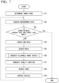
- FIG. 7 is a flowchart showing an automatic traveling process of the control device 140 according to the first embodiment.
- the target determination unit 212 of the control device 140 determines a target pose based on the state of the work vehicle 100 (Step S1).
- the acquisition unit 211 acquires the measurement data of the stroke sensor 1131, the rotation sensor 1123, the detection device 1124, and the positioning device 1125 (Step S2).
- the traveling control unit 217 determines whether an error between the target pose determined in Step S1 and the current pose is equal to or less than a predetermined threshold value (Step S3).
- Step S3 NO
- the map data recorded in the main memory 230 is updated based on the measurement data of the detection device 1124 acquired in Step S2 (Step S4).
- the route search unit 214 searches for a route connecting the current pose of the work vehicle 100 to the target pose determined in Step S1 (Step S5).
- the restriction condition generation unit 215 executes the allowable range series generation process shown in FIG. 5 based on the route searched in Step S5 (Step S6).
- the restriction condition generation unit 215 generates a penalty function based on the generated allowable range series (Step S7).
- the track search unit 216 searches for a track connecting the current pose of the work vehicle 100 to the target pose by using the penalty function generated in Step S7 (Step S8). At this time, the track search unit 216 uses a series of the pose, steering angle, and speed obtained in the route search in Step S5 as an initial value of the search.
- the traveling control unit 217 controls the steering actuator 113, the power source 1121, the power transmission device 1122, and the braking device according to the track obtained in Step S8 (Step S9). Then, the control device 140 returns the process to Step S2.
- Step S3 when an error from the target pose is greater than a threshold value (Step S3: NO), the control device 140 terminates the automatic traveling process. After the automatic excavation process and the automatic release process are executed, the control device 140 performs the automatic traveling process again.
- the control device 140 searches for the route for the work vehicle 100 to move from the initial position to the target position, based on the first restriction condition representing the position of the obstacle, and searches for the track, based on the second restriction condition (penalty function) in which the penalty value increases according to the deviation distance from the route. In this way, the control device 140 searches for the track in two stages with different restriction conditions.
- the restriction conditions used for the track search to the restriction conditions according to the deviation distance from the route, it is possible to weaken the nonlinearity of the restriction conditions related to the track search and suppress an increase in the amount of calculation. That is, the control device 140 can obtain a continuous track with a small amount of calculation.
- control device 140 searches for the route by using a search algorithm having completeness, and searches for the track by using the second search algorithm in which the amount of calculation with respect to the number of elements gradually increases.
- the control device 140 can obtain the route and the track without converging to a local solution while reducing the amount of calculation.
- the penalty function used to search for the track according to the first embodiment is the function in which the penalty value increases according to the deviation distance from the second rectangle that includes each position related to the route and extends in the width direction of the work vehicle 100, and thus, the penalty value is constant when the work vehicle 100 is positioned in the second rectangle. In this way, the control device 140 can obtain a highly linear penalty function.
- the search for the route and the track is performed using the model represented by Equation (1).
- the position (x[k+1], y[k+1]) of the work vehicle 100 after a unit time is represented based on the current position (x[k], y[k+1]) of the work vehicle 100, the turning radius obtained from the steering angle ⁇ [k] of the work vehicle 100, the current posture angle ⁇ [k] of the work vehicle 100, and the posture angle cp[k+1] after a unit time of the work vehicle 100.
- FIG. 8 is a diagram showing a relationship between the time step width and the position of the calculation result in the model according to the first embodiment.
- FIG. 9 is a diagram showing a relationship between the time step width and the position of the calculation result in the model according to a comparative example.
- a vehicle model represented by the following Equation (4) may be used.
- the control device 140 since the control device 140 according to the first embodiment can easily neglect the influence of the time step by using the model represented by Equation (1), it is possible to easily convert the route generated by the route search unit 214 to the track. As a result, the control device 140 can start the track search with the track at which the target state is reached as the initial value without coming into contact with the obstacle obtained by the route search unit 214. By setting a track that reaches the target state as an initial value, the route search unit 214 can calculate an appropriate track without converging to a local solution.
- the control device 140 may be configured by a single computer, or the configuration of the control device 140 may be arranged to be divided into a plurality of computers, and the plurality of computers may function as the control device 140 by cooperating with each other. In this case, some computers constituting the control device 140 may be mounted inside the work vehicle 100, and another computer may be provided outside the work vehicle 100.
- FIG. 10 is a schematic diagram showing a configuration of an automatic driving system 2 according to another embodiment.
- the work vehicle 100 according to the first embodiment autonomously travels under the control of a control device 140 provided therein. Meanwhile, in the automatic driving system 2 shown in FIG. 9 , a control server 800 remotely provided with the work vehicle 100 controls the work vehicle 100.
- the control server 800 and the control device 140 are connected by wireless communication.
- each processing unit shown in FIG. 2 is provided on the control server 800.
- the acquisition unit 211 acquires the measurement data of each measurement device by wireless communication. Further, the traveling control unit 217 transmits a control command to the control device 140 by wireless communication.
- control device 140 uses the dynamic planning method for searching for a route, but is not limited thereto.
- a route may be geometrically generated by a combination of curves such as a straight line, an arc, a Bezier curve, a clothoid curve, and a B-spline curve.
- control device 140 uses a search algorithm that uses a quadratic approximation of the evaluation function in the search for a track, but is not limited thereto.
- control device 140 may obtain a track by re-formulation as a mathematical planning problem.
- control device 140 sets a movable range represented by the second rectangle as a restriction condition for the search for a track, but is not limited thereto.
- restriction condition according to another embodiment may be represented by a line segment that passes through a point related to the route and extends only in the width direction of the work vehicle 100.
- control device 140 obtains the second rectangle R2 based on Equation (3), but is not limited thereto.
- the control device 140 may obtain the second rectangle R2 by a procedure shown below.
- the control device 140 may obtain positions of four vertexes R1, R2, R3, and R4 of the second rectangle R2 by the following Equation (5) by using an azimuth angle ⁇ in the direction in which the obstacle closest to the work vehicle 100 exists and a distance d to the obstacle.
- L indicates a length from the articulate center to the front wheel WF
- l represents a tread width.
- P 1 max 0 , d ⁇ L 2 ⁇ 1 2 cos ⁇ ⁇ 1 2 max 0 , d ⁇ l 2 ⁇ 1 2 sin ⁇ ⁇ 1 2
- P 2 max 0 , d ⁇ L 2 ⁇ 1 2 cos ⁇ ⁇ 1 2 max 0 , ⁇ d ⁇ l 2 ⁇ 1 2 sin ⁇ ⁇ 1 2
- P 3 max 0 , ⁇ d ⁇ L 2 ⁇ 1 2 cos ⁇ ⁇ 1 2 max 0 , d ⁇ l 2 ⁇ 1 2 sin ⁇ ⁇ 1 2
- P 4 max 0 , ⁇ d ⁇ L 2 + 1 2 cos ⁇ ⁇ 1 2 max 0 , ⁇ d ⁇ l 2 + 1 2 sin ⁇ ⁇ 1 2
- the work vehicle 100 according to the first embodiment is a wheel loader that is an articulated vehicle, but is not limited thereto.
- the vehicle according to another embodiment may be another vehicle such as a dump truck or may not be an articulated vehicle.
- the steering angle is an angle between a steered wheel and the vehicle body.
- the work vehicle 100 according to another embodiment may be a crawler vehicle or a vehicle having wheels that cannot be turned, such as a skid steer loader. In this case, for example, the turning radius can be obtained from a speed difference between the left and right crawler belts or the wheels.
- the track search device can obtain a continuous track with a small amount of calculation.
Landscapes
- Engineering & Computer Science (AREA)
- Remote Sensing (AREA)
- Radar, Positioning & Navigation (AREA)
- Automation & Control Theory (AREA)
- Physics & Mathematics (AREA)
- General Physics & Mathematics (AREA)
- Aviation & Aerospace Engineering (AREA)
- Mining & Mineral Resources (AREA)
- Civil Engineering (AREA)
- General Engineering & Computer Science (AREA)
- Structural Engineering (AREA)
- Control Of Position, Course, Altitude, Or Attitude Of Moving Bodies (AREA)
- Operation Control Of Excavators (AREA)
Abstract
Description
- The present disclosure relates to a system, a method, and a work vehicle.
- Priority is claimed on
Japanese Patent Application No. 2021-061381, filed on March 31, 2021 - At a work site such as a crushing site or a mine, an automatic driving system for a work vehicle may be introduced. The automatic driving system calculates a track for the work vehicle to reach a target position, and causes the work vehicle to travel based on the track.
Patent Document 1 discloses a technique related to a method of generating a traveling route of an unmanned vehicle. - [Patent Document 1]
Japanese Unexamined Patent Application, First Publication No. 2010-073080 - Track calculation for a vehicle to travel automatically is an optimization problem. Additionally, in the track calculation, an obstacle present at a work site is given as a restriction condition. However, a mathematical model used to search for a track is represented by multi-dimensional vectors such as a position, posture, steering angle, speed, and acceleration of a vehicle, and a position and shape of obstacles are not necessarily simple, and nonlinearity of the restriction condition may be high. For this reason, it is difficult to calculate a traveling track of the vehicle on-line because the calculation of the track increases an amount of calculation or converges to a local solution. Meanwhile, when the number of dimensions of a model is reduced in order to reduce the amount of calculation, there is a possibility that operations related to the reduced dimensions may be discontinuous in an obtained track.
- An object of the present disclosure is to provide a track search device and a track search method capable of obtaining a continuous track with a small amount of calculation.
- According to a first aspect of the present invention, there is provided a system searching for a track for a vehicle to travel automatically includes a processor. The processor includes a route search unit configured to search for a series having elements of a position and posture of the vehicle, which is a route for moving from an initial position to a target position of the vehicle, based on a first restriction condition representing a position of an obstacle, a restriction condition generation unit configured to generate a second restriction condition in which a penalty value increases according to a deviation distance from the route, and a track search unit configured to search for a series having elements of a position, posture, speed, and steering angle of the vehicle, which is a track for moving from the initial position to the target position of the vehicle, based on the second restriction condition.
- According to a second aspect of the present invention, there is provided a method of searching for a track for a vehicle to travel automatically. The method includes the following processes. In a first process, a series having elements of a position and posture of the vehicle, which is a route for moving from an initial position to a target position of the vehicle, is searched for based on a first restriction condition representing a position of an obstacle. In a second process, a second restriction condition is generated, in which a penalty value increases according to a deviation distance from the route. In a third process, a series having elements of a position, posture, speed, and steering angle of the vehicle, which is a track for moving from the initial position to the target position of the vehicle, is searched for based on the second restriction condition.
- According to a third mode of the present invention, there is provided a work vehicle including: a vehicle body; a traveling device for causing the vehicle body to travel; and a processor. The processor includes a route search unit configured to search for a series having elements of a position and posture of the work vehicle, which is a route for moving from an initial position to a target position of the work vehicle, based on a first restriction condition representing a position of an obstacle, a restriction condition generation unit configured to generate a second restriction condition in which a penalty value increases according to a deviation distance from the route, a track search unit configured to search for a series having elements of a position, posture, speed, and steering angle of the work vehicle, which is a track for moving from the initial position to the target position of the work vehicle, based on the second restriction condition, and a traveling control unit configured to control the traveling device according to the track.
- According to at least one of the above aspects, the track search device can obtain a continuous track with a small amount of calculation.
-
-
FIG. 1 is a side view of a work vehicle according to a first embodiment. -
FIG. 2 is a schematic block diagram showing a configuration of a control device according to the first embodiment. -
FIG. 3 is a diagram showing an example of map data according to the first embodiment. -
FIG. 4 is a diagram showing an example of an allowable range series according to the first embodiment. -
FIG. 5 is a flowchart showing a method of generating the allowable range series according to the first embodiment. -
FIG. 6 is a diagram showing a relationship between a first rectangle and a second rectangle according to the first embodiment. -
FIG. 7 is a flowchart showing an automatic traveling process of the control device according to the first embodiment. -
FIG. 8 is a diagram showing a relationship between a time step width and a position of a calculation result in a model according to the first embodiment. -
FIG. 9 is a diagram showing a relationship between a time step width and a position of a calculation result in a model according to a comparative example. -
FIG. 10 is a schematic diagram showing a configuration of an automatic driving system according to another embodiment. - Hereinafter, embodiments will be described in detail with reference to the drawings.
-
FIG. 1 is a side view of a work vehicle according to a first embodiment. - A
work vehicle 100 according to the first embodiment is a wheel loader. Thework vehicle 100 is driven by automatic operation. That is, thework vehicle 100 is an unmanned traveling vehicle. Thework vehicle 100 includes avehicle body 110,work equipment 120, and acontrol device 140. - The
vehicle body 110 includes afront vehicle body 111, arear vehicle body 112, and asteering actuator 113. Thefront vehicle body 111 and therear vehicle body 112 are rotatably attached around a steering shaft extending in a vertical direction of thevehicle body 110. A pair of front wheels WF is provided at a lower portion of thefront vehicle body 111. A pair of rear wheels WR is provided at a lower portion of therear vehicle body 112. - The
rear vehicle body 112 includes apower source 1121 and apower transmission device 1122. Thepower source 1121 is, for example, a diesel engine. Thepower transmission device 1122 shifts a speed of a driving force input to an input shaft, and outputs the speed from the output shaft. The output shaft of thepower transmission device 1122 is connected to the front wheel WF via a front axle (not shown) and is connected to the rear wheel WR via a rear axle (not shown). The front axle supports thefront vehicle body 111 to be able to travel. The rear axle supports therear vehicle body 112 so as to be able to travel. The front axle and the rear axle are provided with braking devices (not shown). Thepower transmission device 1122 is provided with arotation sensor 1123. Therotation sensor 1123 measures a rotation speed of the output shaft of thepower transmission device 1122. Thecontrol device 140 can specify the speed and the acceleration of thework vehicle 100 based on measurement data of therotation sensor 1123. Further, adetection device 1124 and apositioning device 1125 are provided on the upper portion of therear vehicle body 112. Thedetection device 1124 detects a three-dimensional position of an object present around thework vehicle 100. A Light Detection and Ranging (LiDar), a stereo camera, an ultra wide band (UWB) distance measuring device, and the like are exemplary examples of thedetection device 1124. Thedetection device 1124 is provided, for example, such that a detection direction faces the front. Thepositioning device 1125 measures a position and a posture (posture angle) of thework vehicle 100 in global coordinates by a Global Navigation Satellite System (GNSS) or the like. The position is represented by, for example, latitude and longitude. The posture is represented by, for example, an azimuth angle of therear vehicle body 112 with the north as a reference azimuth. Hereinafter, the position and posture of thework vehicle 100 will also be referred to as a pose of thework vehicle 100. - The
steering actuator 113 is, for example, a hydraulic cylinder. A proximal end portion of thesteering actuator 113 is attached to therear vehicle body 112, and a distal end portion thereof is attached to thefront vehicle body 111. Thesteering actuator 113 expands and contracts by hydraulic oil to define an angle formed between thefront vehicle body 111 and therear vehicle body 112. That is, the expansion and contraction of thesteering actuator 113 defines the steering angle of the front wheels WF. Thesteering actuator 113 is provided with astroke sensor 1131 that measures a stroke length of thesteering actuator 113. Thecontrol device 140 can specify the steering angle of thework vehicle 100 based on the measurement data of thestroke sensor 1131. - The
power transmission device 1122, the braking device, and thesteering actuator 113 are traveling devices for causing thevehicle body 110 to travel. - The
work equipment 120 is used for excavating and transporting a work object such as earth. Thework equipment 120 is provided in a front part of thevehicle body 110. - The
control device 140 causes thework vehicle 100 to travel based on the detection data of thedetection device 1124. -
FIG. 2 is a schematic block diagram showing a configuration of thecontrol device 140 according to the first embodiment. - The
control device 140 is a computer including aprocessor 210, amain memory 230, astorage 250, and aninterface 270. - The
storage 250 is a non-transitory, tangible storage medium. A magnetic disk, an optical disk, a magneto-optical disk, a semiconductor memory, and the like are exemplary examples of thestorage 250. Thestorage 250 may be an internal medium directly connected to the bus of thecontrol device 140, or an external medium connected to thecontrol device 140 via theinterface 270 or a communication line. Thestorage 250 stores a program for controlling thework vehicle 100. - The program may be for realizing some of functions exerted by the
control device 140. For example, the program may exert functions in combination with other programs already stored in thestorage 250 or in combination with other programs mounted on other devices. In another embodiment, thecontrol device 140 may include a custom Large Scale Integrated Circuit (LSI) such as a Programmable Logic Device (PLD) in addition to or in place of the above configuration. A Programmable Array Logic (PAL), a Generic Array Logic (GAL), a Complex Programmable Logic Device (CPLD), and a Field Programmable Gate Array (FPGA) are exemplary examples of the PLD. In this case, some or all of the functions realized by the processor may be realized by the integrated circuit. - The
processor 210 includes anacquisition unit 211, amap generation unit 213, atarget determination unit 212, aroute search unit 214, a restrictioncondition generation unit 215, atrack search unit 216, and a travelingcontrol unit 217 by executing a program. Thecontrol device 140 is an example of a track search device. - The
acquisition unit 211 acquires the measurement data of thestroke sensor 1131, therotation sensor 1123, thedetection device 1124, and thepositioning device 1125. Accordingly, theacquisition unit 211 specifies the position, the posture angle, the steering angle, the speed, and the acceleration of thework vehicle 100, and the position of an obstacle present around thework vehicle 100. - The
map generation unit 213 generates map data representing the periphery of thework vehicle 100 by using the measurement data of thedetection device 1124 acquired by theacquisition unit 211, and the measurement data of thepositioning device 1125. Themap generation unit 213 generates map data by using, for example, Simultaneous Localization and Mapping (SLAM) technology. The map data is represented by, for example, an occupied grid map related to a global coordinate system.FIG. 3 is a diagram showing an example of the map data according to the first embodiment. Further, a score representing the distance from the obstacle is attached to each grid of the map data. A score of a grid representing a position where the obstacle exists is zero, and the farther the distance from the obstacle is, the higher the score. The score is represented by, for example, a Manhattan distance from the closest obstacle. - Since the
detection device 1124 is fixed to therear vehicle body 112, themap generation unit 213 moves the position of the obstacle indicated by the measurement data of thedetection device 1124 in parallel based on the position indicated by the measurement data of thepositioning device 1125, and the position of the obstacle in the global coordinate system can be specified by the rotation based on the posture angle. The map data generated by themap generation unit 213 is recorded in themain memory 230. - The
target determination unit 212 determines a target pose (target position) of thework vehicle 100. For example, thetarget determination unit 212 determines a position of a loading site designated in advance and a posture angle facing the loading site to the target pose in a case where the earth is not held by thework equipment 120. Further, thetarget determination unit 212 determines a position of a release site designated in advance and a posture angle facing the release site as the target pose in a case where the earth is held by thework equipment 120. At this time, for example, thetarget determination unit 212 may correct the positions of the loading site and the release site based on the map data. - The
route search unit 214 searches for a route connecting a current pose (initial position) of thework vehicle 100 acquired by theacquisition unit 211 to a target pose determined by atarget determination unit 212. The "route" is represented by an ordinal set of poses. That is, the route obtained by theroute search unit 214 is a series of the position and the posture angle of thework vehicle 100. Theroute search unit 214 searches for a route by using a complete search algorithm (first search algorithm) such as a dynamic planning method. The Dixstra method, the hybrid A*, and the like are exemplary examples of the algorithm related to the dynamic planning method. When the hybrid A* is used, a heuristic cost can be obtained by a Reeds Shepp method or a Laplace Potential method. The Reeds Shepp method is a method for finding a shortest route of a non-holonomic system when an obstacle or the continuity of curvature is ignored. The Laplace Potential method is a method for obtaining the shortest route when a non-holonomic restriction is ignored. - The restriction condition (first restriction condition) for the search by the
route search unit 214 is that themap generation unit 213 does not contact the obstacle represented by the generated map data, that the pose at an end point matches the target pose, and the steering angle is within a predetermined movable range. The evaluation function of the search by theroute search unit 214 is a function whose value decreases as the travel distance becomes shorter. The model used for the search by theroute search unit 214 is represented by Equation (1).
- In Equation (1), x[k] indicates an x-coordinate (for example, latitude) at time k. y[k] indicates a y-coordinate (for example, longitude) at time k. ϕ[k] indicates a posture angle at time k. δ[k] indicates a steering angle at time k. v[k] indicates a speed at time k. k+1 represents a time after a unit time of time k. Δt indicates a time step width. L indicates a length from an articulate center to the front wheel WF. That is, a mathematical model used by the
route search unit 214 is a model of three elements of the x-coordinate, y-coordinate, and posture angle of thework vehicle 100, and does not include the steering angle and speed as elements. - While the search algorithm related to the dynamic planning method has completeness, the amount of calculation increases exponentially with respect to the number of dimensions of a model or an input. Therefore, the
route search unit 214 according to the first embodiment can reduce the amount of calculation by reducing the number of elements of the model. - In addition, in Equation (1), L/tan(δ[k]) represents a turning radius of the
work vehicle 100. That is, in Equation (1), an increment in the x-coordinate is represented as a value obtained by multiplying a difference between a sine of a posture angle ϕ[k] and a sine of a posture angle ϕ[k+1] by a turning radius of thework vehicle 100 at time k. Similarly, in Equation (1), an increment in a y-coordinate is represented as a value obtained by multiplying a difference between a cosine of the posture angle cp[k] and a cosine of a posture angle ϕ[k+1] by the turning radius of thework vehicle 100 at time k. - The
route search unit 214 acquires a series of poses of thework vehicle 100 as a route by performing a search based on the model represented by Equation (1). Although the model represented by Equation (1) uses time as an index, the index of the route is not treated as representing time in the restrictioncondition generation unit 215. For example, the pose x[i] in the route does not indicate the pose at time i, but simply indicates the i-th pose. Meanwhile, time series of the steering angle and the speed obtained by theroute search unit 214 are used as initial values of thetrack search unit 216 which will be described later. It should be noted that, since the model used by theroute search unit 214 is a pose model and does not include the steering angle and the speed as elements, the series of the searched steering angles and accelerations lacks continuity. That is, the route searched for by theroute search unit 214 may have a discontinuous curvature or may include unnecessary switchback. - The restriction
condition generation unit 215 generates a restriction condition (second restriction condition) to be used for the search by thetrack search unit 216 based on the route obtained by theroute search unit 214. The restriction condition used for the search by thetrack search unit 216 is that the position of thework vehicle 100 is located within the allowable range series including the route obtained by theroute search unit 214. The restriction condition is represented by a penalty function in which a penalty value increases according to a deviation distance from the allowable range series, and a penalty value when thework vehicle 100 is positioned within the allowable range series is zero.FIG. 4 is a diagram showing an example of an allowable range series according to the first embodiment. The allowable range series is a series of allowable ranges represented by a rectangle. The allowable range is represented by the coordinates of four vertexes of the rectangle. The restrictioncondition generation unit 215 determines the allowable range series based on the map data generated by themap generation unit 213 and the route generated by theroute search unit 214. As the route is converted into an allowable range series by the restrictioncondition generation unit 215, the discontinuity of the curvature of the route and unnecessary switchback can be ignored. - The restriction
condition generation unit 215 generates an allowable range series by the following procedure.FIG. 5 is a flowchart showing the generation method of the allowable range series according to the first embodiment. - The restriction
condition generation unit 215 selects a pose one by one from the series of poses related to the route (Step S51), and executes the following processes of Steps S52 to S56 for the selected poses. The restrictioncondition generation unit 215 disposes a first rectangle R1 representing an outer shape of thework vehicle 100 on the map data recorded in themain memory 230 based on the pose selected in Step S51 (Step S52). The restrictioncondition generation unit 215 calculates a distance (Euclidean distance) from each point to the closest obstacle based on the scores of a plurality of grids that overlap a plurality of points set on four sides of the first rectangle R1 in the map data (Step S53).FIG. 6 is a diagram showing a relationship between the first rectangle R1 and a second rectangle R2 according to the first embodiment. In a case where the first rectangle R1 includes two long sides E1 and E2 and two short sides E3 and E4, for example, four vertexes p1, p3, p6, and p8 of the first rectangle, two points p4 and p5 dividing the long side E1 into three, two points p9 and p10 dividing the long side E2 into three, a point p2 dividing the short side E3 into two, and a point p7 dividing the short side E4 into two are set. Since the score according to the first embodiment represents the Manhattan distance from the obstacle, a distance d to the obstacle can be obtained by the following Equation (2) using the score n.
- Based on the map data, the restriction
condition generation unit 215 specifies the shortest distance d among the distances d obtained in Step S53 for each of the four sides of the first rectangle (Step S54). The restrictioncondition generation unit 215 obtains the positions of the four vertexes P1, P2, P3, and P4 of the second rectangle R2 representing the allowable range by the following Equation (3) by using the distance d obtained in Step S54 (Step S55).
- That is, the allowable range is represented by a second rectangle R2 that includes a center point p0 of a first rectangle R1 representing the
work vehicle 100. - The restriction
condition generation unit 215 determines a position and azimuth angle of the allowable range in the global coordinate system by arranging the rectangle of the allowable range calculated based on the pose selected in Step S51 (Step S56). - The restriction
condition generation unit 215 can obtain the allowable range series by executing the above-described processing from Step S52 to Step S56 for all the poses of the route. - The
track search unit 216 shown inFIG. 2 searches for a track connecting the current pose of thework vehicle 100 acquired by theacquisition unit 211 to the target pose determined by thetarget determination unit 212. The "track" is represented by a series of poses with time as a parameter. That is, thetrack search unit 216 obtains the pose for each time of thework vehicle 100, and a series of steering angles and speeds for realizing the pose for each time, as the track. Thetrack search unit 216 searches for a track by a search algorithm (second search algorithm) that uses a quadratic approximation of the evaluation function. A differential dynamic planning method, an iterative linear quadratic regulator (iLQR), a sequential quadratic programming (SQP), and the like are exemplary examples of the search algorithm that uses the quadratic approximation of the evaluation function. - The search by the
track search unit 216 is performed such that an evaluation value obtained by the sum of the evaluation function whose value decreases as the traveling time becomes shorter and the penalty function generated by the restrictioncondition generation unit 215 is minimized. In the search by thetrack search unit 216, the time step width Δt represented by Equation (1) is also an optimization target. - In the search algorithm using the quadratic approximation of the evaluation function, an increase in the amount of calculation with respect to the number of dimensions is gradual as compared with a search algorithm related to the dynamic planning method. Therefore, even when the steering angle, the speed, and the time step width are added to the optimization targets, the calculation amount does not explode. Meanwhile, the search algorithm that uses the quadratic approximation of the evaluation function does not have completeness, such as when the nonlinearity of a restriction conditions is strong, it may converge to a local solution. Therefore, by using the restriction condition that can be represented by a linear function generated by the restriction
condition generation unit 215, it is possible to simplify the problem and prevent convergence to a local solution. - The traveling
control unit 217 controls thesteering actuator 113, thepower source 1121, thepower transmission device 1122, and the braking device according to the track obtained by thetrack search unit 216. That is, the travelingcontrol unit 217 reads out a steering angle and a speed related to a current time from a series related to the track, controls thesteering actuator 113 to realize the steering angle, and controls thepower source 1121, thepower transmission device 1122 and the braking device to realize the speed. -
FIG. 7 is a flowchart showing an automatic traveling process of thecontrol device 140 according to the first embodiment. - The
target determination unit 212 of thecontrol device 140 determines a target pose based on the state of the work vehicle 100 (Step S1). Theacquisition unit 211 acquires the measurement data of thestroke sensor 1131, therotation sensor 1123, thedetection device 1124, and the positioning device 1125 (Step S2). Based on the measurement data of thepositioning device 1125 acquired in Step S2, the travelingcontrol unit 217 determines whether an error between the target pose determined in Step S1 and the current pose is equal to or less than a predetermined threshold value (Step S3). - In a case where the error from the target pose is greater than the threshold value (Step S3: NO), the map data recorded in the
main memory 230 is updated based on the measurement data of thedetection device 1124 acquired in Step S2 (Step S4). Theroute search unit 214 searches for a route connecting the current pose of thework vehicle 100 to the target pose determined in Step S1 (Step S5). - Next, the restriction
condition generation unit 215 executes the allowable range series generation process shown inFIG. 5 based on the route searched in Step S5 (Step S6). The restrictioncondition generation unit 215 generates a penalty function based on the generated allowable range series (Step S7). Thetrack search unit 216 searches for a track connecting the current pose of thework vehicle 100 to the target pose by using the penalty function generated in Step S7 (Step S8). At this time, thetrack search unit 216 uses a series of the pose, steering angle, and speed obtained in the route search in Step S5 as an initial value of the search. - The traveling
control unit 217 controls thesteering actuator 113, thepower source 1121, thepower transmission device 1122, and the braking device according to the track obtained in Step S8 (Step S9). Then, thecontrol device 140 returns the process to Step S2. - In Step S3, when an error from the target pose is greater than a threshold value (Step S3: NO), the
control device 140 terminates the automatic traveling process. After the automatic excavation process and the automatic release process are executed, thecontrol device 140 performs the automatic traveling process again. - The
control device 140 according to the first embodiment searches for the route for thework vehicle 100 to move from the initial position to the target position, based on the first restriction condition representing the position of the obstacle, and searches for the track, based on the second restriction condition (penalty function) in which the penalty value increases according to the deviation distance from the route. In this way, thecontrol device 140 searches for the track in two stages with different restriction conditions. By setting the restriction conditions used for the track search to the restriction conditions according to the deviation distance from the route, it is possible to weaken the nonlinearity of the restriction conditions related to the track search and suppress an increase in the amount of calculation. That is, thecontrol device 140 can obtain a continuous track with a small amount of calculation. - In addition, the
control device 140 according to the first embodiment searches for the route by using a search algorithm having completeness, and searches for the track by using the second search algorithm in which the amount of calculation with respect to the number of elements gradually increases. As a result, thecontrol device 140 can obtain the route and the track without converging to a local solution while reducing the amount of calculation. - In addition, the penalty function used to search for the track according to the first embodiment is the function in which the penalty value increases according to the deviation distance from the second rectangle that includes each position related to the route and extends in the width direction of the
work vehicle 100, and thus, the penalty value is constant when thework vehicle 100 is positioned in the second rectangle. In this way, thecontrol device 140 can obtain a highly linear penalty function. - Further, in the first embodiment, the search for the route and the track is performed using the model represented by Equation (1). In the model represented by Equation (1), the position (x[k+1], y[k+1]) of the
work vehicle 100 after a unit time is represented based on the current position (x[k], y[k+1]) of thework vehicle 100, the turning radius obtained from the steering angle δ[k] of thework vehicle 100, the current posture angle ϕ[k] of thework vehicle 100, and the posture angle cp[k+1] after a unit time of thework vehicle 100. -
FIG. 8 is a diagram showing a relationship between the time step width and the position of the calculation result in the model according to the first embodiment.FIG. 9 is a diagram showing a relationship between the time step width and the position of the calculation result in the model according to a comparative example. - As the vehicle model, a vehicle model represented by the following Equation (4) may be used.

- However, in the model represented by Equation (4), since the increment in the x-coordinate and the increment in the y-coordinate are close to linear movement, when a value of a time step width Δt changes, the position is calculated as shown in
FIG. 9 . There will be errors in the results. Meanwhile, in the model represented by Equation (1), since the increment in the x-coordinate and the increment in the y-coordinate are close to an arc by the turning radius and the posture angle, as shown inFIG. 8 , even when the value of the time step width Δt changes, no error occurs in the calculation result of the position. Therefore, since thecontrol device 140 according to the first embodiment can easily neglect the influence of the time step by using the model represented by Equation (1), it is possible to easily convert the route generated by theroute search unit 214 to the track. As a result, thecontrol device 140 can start the track search with the track at which the target state is reached as the initial value without coming into contact with the obstacle obtained by theroute search unit 214. By setting a track that reaches the target state as an initial value, theroute search unit 214 can calculate an appropriate track without converging to a local solution. - Although one embodiment has been described in detail above with reference to the drawings, the specific configuration is not limited to the one described above, and various design changes and the like can be made. That is, in other embodiments, the order of the processes described above may be changed as appropriate. Moreover, some processes may be executed in parallel.
- The
control device 140 according to the above-described embodiment may be configured by a single computer, or the configuration of thecontrol device 140 may be arranged to be divided into a plurality of computers, and the plurality of computers may function as thecontrol device 140 by cooperating with each other. In this case, some computers constituting thecontrol device 140 may be mounted inside thework vehicle 100, and another computer may be provided outside thework vehicle 100. -
FIG. 10 is a schematic diagram showing a configuration of anautomatic driving system 2 according to another embodiment. Thework vehicle 100 according to the first embodiment autonomously travels under the control of acontrol device 140 provided therein. Meanwhile, in theautomatic driving system 2 shown inFIG. 9 , acontrol server 800 remotely provided with thework vehicle 100 controls thework vehicle 100. Thecontrol server 800 and thecontrol device 140 are connected by wireless communication. - In this case, each processing unit shown in
FIG. 2 is provided on thecontrol server 800. Theacquisition unit 211 acquires the measurement data of each measurement device by wireless communication. Further, the travelingcontrol unit 217 transmits a control command to thecontrol device 140 by wireless communication. - In addition, the
control device 140 according to the first embodiment uses the dynamic planning method for searching for a route, but is not limited thereto. For example, in other embodiments, a route may be geometrically generated by a combination of curves such as a straight line, an arc, a Bezier curve, a clothoid curve, and a B-spline curve. - In addition, the
control device 140 according to the first embodiment uses a search algorithm that uses a quadratic approximation of the evaluation function in the search for a track, but is not limited thereto. For example, in another embodiment, thecontrol device 140 may obtain a track by re-formulation as a mathematical planning problem. - In addition, the
control device 140 according to the first embodiment sets a movable range represented by the second rectangle as a restriction condition for the search for a track, but is not limited thereto. For example, the restriction condition according to another embodiment may be represented by a line segment that passes through a point related to the route and extends only in the width direction of thework vehicle 100. - In addition, the
control device 140 according to the first embodiment obtains the second rectangle R2 based on Equation (3), but is not limited thereto. For example, thecontrol device 140 according to another embodiment may obtain the second rectangle R2 by a procedure shown below. Thecontrol device 140 may obtain positions of four vertexes R1, R2, R3, and R4 of the second rectangle R2 by the following Equation (5) by using an azimuth angle α in the direction in which the obstacle closest to thework vehicle 100 exists and a distance d to the obstacle. In Equation (5), L indicates a length from the articulate center to the front wheel WF, and l represents a tread width.
- In addition, the
work vehicle 100 according to the first embodiment is a wheel loader that is an articulated vehicle, but is not limited thereto. For example, the vehicle according to another embodiment may be another vehicle such as a dump truck or may not be an articulated vehicle. In a case where the vehicle is not an articulated vehicle, for example, the steering angle is an angle between a steered wheel and the vehicle body. In addition, thework vehicle 100 according to another embodiment may be a crawler vehicle or a vehicle having wheels that cannot be turned, such as a skid steer loader. In this case, for example, the turning radius can be obtained from a speed difference between the left and right crawler belts or the wheels. - According to at least one of the above aspects, the track search device can obtain a continuous track with a small amount of calculation.
-
- 100: Work vehicle
- 110: Vehicle body
- 111: Front vehicle body
- 112: Rear vehicle body
- 1121: Power source
- 1122: Power transmission device
- 1123: Rotation sensor
- 1124: Detection device
- 1125: Positioning device
- 113: Steering actuator
- 1131: Stroke sensor
- 120: Work equipment
- 140: Control device
- 210: Processor
- 211: Acquisition unit
- 212: Target determination unit
- 213: Map generation unit
- 214: Route search unit
- 215: Restriction condition generation unit
- 216: Track search unit
- 217: Traveling control unit
- 230: Main memory
- 250: Storage
- 270: Interface
- WF: Front wheel
- WR: Rear wheel
- 800: Control server
- 2: Automatic driving system
Claims (11)
- A system that searches for a track for a vehicle to travel automatically, the system comprising a processor,wherein the processor includesa route search unit configured to search for a series having elements of a position and posture of the vehicle, which is a route for moving from an initial position to a target position of the vehicle, based on a first restriction condition representing a position of an obstacle,a restriction condition generation unit configured to generate a second restriction condition in which a penalty value increases according to a deviation distance from the route, anda track search unit configured to search for a series having elements of a position, posture, speed, and steering angle of the vehicle, which is a track for moving from the initial position to the target position of the vehicle, based on the second restriction condition.
- The system according to Claim 1,wherein the route search unit searches for the route by using a first search algorithm having completeness, andthe track search unit searches for the track by using a second search algorithm in which an amount of calculation increases more slowly with respect to the number of elements than the first search algorithm.
- The system according to Claim 1 or 2,
wherein the second restriction condition is a condition in which the penalty value increases according to a deviation distance from a region including a position related to each element of the route and extending in a width direction of the vehicle, and the penalty value is constant when the vehicle is positioned within the region. - The system according to Claim 3,
wherein the restriction condition generation unit generates the second restriction condition based on the position of the obstacle, and the position and the posture related to each element of the route. - The system according to any one of Claims 1 to 4,wherein the route search unit searches for the route based on a model representing the vehicle, andthe model represents a position of the vehicle after a unit time based on a current position of the vehicle, a turning radius obtained from the steering angle of the vehicle, a current posture angle of the vehicle, and a posture angle of the vehicle after the unit time.
- A method of searching for a track for a vehicle to travel automatically, the method comprising:a step of searching for a series having elements of a position and posture of the vehicle, which is a route for moving from an initial position to a target position of the vehicle, based on a first restriction condition representing a position of an obstacle;a step of generating a second restriction condition in which a penalty value increases according to a deviation distance from the route; anda step of searching for a series having elements of a position, posture, speed, and steering angle of the vehicle, which is a track for moving from the initial position to the target position of the vehicle, based on the second restriction condition.
- The method according to claim 6,wherein in the step of searching for the route, the route is searched for by using a first search algorithm having completeness, andin the step of searching for the track, the track is searched for by using a second search algorithm in which an amount of calculation increases more slowly with respect to the number of elements than the first search algorithm.
- The method according to claim 6 or 7,
wherein the second restriction condition is a condition in which the penalty value increases according to a deviation distance from a region including a position related to each element of the route and extending in a width direction of the vehicle, and the penalty value is constant when the vehicle is positioned within the region. - The method according to claim 8,
wherein in the step of generating the second restriction condition, the second restriction condition is generated based on the position of the obstacle, and the position and the posture related to each element of the route. - The method according to any one of claims 6 to 9,wherein in the step of searching for the route, the route is searched for based on a model representing the vehicle, andthe model represents a position of the vehicle after a unit time based on a current position of the vehicle, a turning radius obtained from the steering angle of the vehicle, a current posture angle of the vehicle, and a posture angle of the vehicle after the unit time.
- A work vehicle comprising:a vehicle body;a traveling device for causing the vehicle body to travel; anda processor,wherein the processor includesa route search unit configured to search for a series having elements of a position and posture of the work vehicle, which is a route for moving from an initial position to a target position of the work vehicle, based on a first restriction condition representing a position of an obstacle,a restriction condition generation unit configured to generate a second restriction condition in which a penalty value increases according to a deviation distance from the route,a track search unit configured to search for a series having elements of a position, posture, speed, and steering angle of the work vehicle, which is a track for moving from the initial position to the target position of the work vehicle, based on the second restriction condition, anda traveling control unit configured to control the traveling device according to the track.
Applications Claiming Priority (2)
| Application Number | Priority Date | Filing Date | Title |
|---|---|---|---|
| JP2021061381A JP7626649B2 (en) | 2021-03-31 | 2021-03-31 | SYSTEM, METHOD AND WORK VEHICLE |
| PCT/JP2022/007611 WO2022209465A1 (en) | 2021-03-31 | 2022-02-24 | System, method, and work vehicle |
Publications (3)
| Publication Number | Publication Date |
|---|---|
| EP4290020A1 true EP4290020A1 (en) | 2023-12-13 |
| EP4290020A4 EP4290020A4 (en) | 2025-01-15 |
| EP4290020B1 EP4290020B1 (en) | 2026-01-21 |
Family
ID=83458370
Family Applications (1)
| Application Number | Title | Priority Date | Filing Date |
|---|---|---|---|
| EP22779690.1A Active EP4290020B1 (en) | 2021-03-31 | 2022-02-24 | System, method, and work vehicle |
Country Status (5)
| Country | Link |
|---|---|
| US (1) | US12461542B2 (en) |
| EP (1) | EP4290020B1 (en) |
| JP (1) | JP7626649B2 (en) |
| CN (1) | CN116964539A (en) |
| WO (1) | WO2022209465A1 (en) |
Families Citing this family (7)
| Publication number | Priority date | Publication date | Assignee | Title |
|---|---|---|---|---|
| JP2024119548A (en) | 2023-02-22 | 2024-09-03 | 株式会社小松製作所 | SYSTEM INCLUDING WORK MACHINE, CONTROLLER FOR WORK MACHINE, AND ROUTE GENERATION METHOD FOR WORK MACHINE |
| JP2024119549A (en) | 2023-02-22 | 2024-09-03 | 株式会社小松製作所 | SYSTEM INCLUDING WORK MACHINE, CONTROLLER FOR WORK MACHINE, AND ROUTE GENERATION METHOD FOR WORK MACHINE |
| CN116481557B (en) * | 2023-06-20 | 2023-09-08 | 北京斯年智驾科技有限公司 | Intersection passing path planning method and device, electronic equipment and storage medium |
| JP2025104123A (en) * | 2023-12-27 | 2025-07-09 | 株式会社小松製作所 | PLANNING DEVICE, WORK MACHINE, TRANSPORT VEHICLE, AND PLANNING METHOD |
| JP2025114291A (en) * | 2024-01-24 | 2025-08-05 | 株式会社小松製作所 | Work machine control system and work machine control method |
| JP2025118266A (en) * | 2024-01-31 | 2025-08-13 | 株式会社小松製作所 | Work machine control system, work machine, and work machine control method |
| JP2025132254A (en) * | 2024-02-29 | 2025-09-10 | 株式会社小松製作所 | Work site management system and work site management method |
Family Cites Families (20)
| Publication number | Priority date | Publication date | Assignee | Title |
|---|---|---|---|---|
| JP5332034B2 (en) | 2008-09-22 | 2013-11-06 | 株式会社小松製作所 | Driving route generation method for unmanned vehicles |
| JP2014026516A (en) * | 2012-07-27 | 2014-02-06 | Nissan Motor Co Ltd | Target route generation device and target route generation method |
| JP6728633B2 (en) * | 2015-10-30 | 2020-07-22 | 日産自動車株式会社 | Electric vehicle control method and control device |
| CN105551284A (en) * | 2016-01-29 | 2016-05-04 | 武汉光庭科技有限公司 | Open-type automatic driving system |
| US9826500B1 (en) * | 2016-05-11 | 2017-11-21 | International Business Machines Corporation | Preventing driver distraction from incoming notifications |
| US20190004524A1 (en) * | 2016-08-31 | 2019-01-03 | Faraday&Future Inc. | System and method for planning a vehicle path |
| CN107702716B (en) | 2017-08-31 | 2021-04-13 | 广州小鹏汽车科技有限公司 | A method, system and device for unmanned path planning |
| US10571921B2 (en) * | 2017-09-18 | 2020-02-25 | Baidu Usa Llc | Path optimization based on constrained smoothing spline for autonomous driving vehicles |
| US10429847B2 (en) * | 2017-09-22 | 2019-10-01 | Locus Robotics Corp. | Dynamic window approach using optimal reciprocal collision avoidance cost-critic |
| US10816977B2 (en) * | 2018-01-26 | 2020-10-27 | Baidu Usa Llc | Path and speed optimization fallback mechanism for autonomous vehicles |
| US11360482B2 (en) * | 2018-01-29 | 2022-06-14 | Baidu Usa Llc | Method and system for generating reference lines for autonomous driving vehicles using multiple threads |
| CN108322708B (en) * | 2018-02-12 | 2020-07-31 | 福州大学 | Real-time video transmission system and method based on multi-channel parallel transmission technology |
| US10739768B2 (en) * | 2018-08-08 | 2020-08-11 | Toyota Motor Engineering & Manufacturing North America, Inc. | Smoothed and regularized Fischer-Burmeister solver for embedded real-time constrained optimal control problems in autonomous systems |
| US11237572B2 (en) * | 2018-12-27 | 2022-02-01 | Intel Corporation | Collision avoidance system, depth imaging system, vehicle, map generator and methods thereof |
| US10928827B2 (en) * | 2019-01-07 | 2021-02-23 | Toyota Research Institute, Inc. | Systems and methods for generating a path for a vehicle |
| CN111796588B (en) * | 2019-03-22 | 2025-02-25 | 北京京东乾石科技有限公司 | Path planning method, path planning device and computer readable storage medium |
| CN110362096B (en) * | 2019-08-13 | 2021-05-18 | 东北大学 | Unmanned vehicle dynamic trajectory planning method based on local optimality |
| JP2021033685A (en) * | 2019-08-26 | 2021-03-01 | 株式会社デンソー | Learning program and learning method |
| JP7408335B2 (en) | 2019-10-09 | 2024-01-05 | 株式会社ディスコ | Workpiece storage mechanism |
| CN110792295B (en) * | 2019-11-25 | 2021-02-19 | 北京航空航天大学 | Device for automatically returning car carrier to center and keeping spacing and control method thereof |
-
2021
- 2021-03-31 JP JP2021061381A patent/JP7626649B2/en active Active
-
2022
- 2022-02-24 WO PCT/JP2022/007611 patent/WO2022209465A1/en not_active Ceased
- 2022-02-24 EP EP22779690.1A patent/EP4290020B1/en active Active
- 2022-02-24 CN CN202280019618.5A patent/CN116964539A/en active Pending
- 2022-02-24 US US18/548,800 patent/US12461542B2/en active Active
Also Published As
| Publication number | Publication date |
|---|---|
| JP2022157259A (en) | 2022-10-14 |
| EP4290020B1 (en) | 2026-01-21 |
| US12461542B2 (en) | 2025-11-04 |
| WO2022209465A1 (en) | 2022-10-06 |
| US20240152155A1 (en) | 2024-05-09 |
| JP7626649B2 (en) | 2025-02-04 |
| EP4290020A4 (en) | 2025-01-15 |
| CN116964539A (en) | 2023-10-27 |
Similar Documents
| Publication | Publication Date | Title |
|---|---|---|
| EP4290020B1 (en) | System, method, and work vehicle | |
| CN110260867B (en) | Method, equipment and device for determining and correcting neutral position in robot navigation | |
| CN112327830B (en) | Planning method for automatic driving lane-changing track of vehicle and electronic equipment | |
| US8224525B1 (en) | Indication of attraction domains for controlled planar motion of a ground vehicle | |
| CN109799828B (en) | Transverse and longitudinal coordination control method for automatic driving vehicle | |
| US20080059015A1 (en) | Software architecture for high-speed traversal of prescribed routes | |
| JP2022027593A (en) | Positioning method and device for movable equipment, and movable equipment | |
| JP7133298B2 (en) | Transportation vehicle control system and transportation vehicle management method | |
| CN115900738B (en) | Path planning methods, devices, vehicles, and storage media | |
| JP2010134742A (en) | Movement control device having obstacle avoiding function | |
| EP4250047B1 (en) | Dump truck control system | |
| JP2015138418A (en) | Map generation system | |
| JP2014232509A (en) | Route generation method and device | |
| CN114967710A (en) | Automatic driving obstacle avoidance path planning system and method based on control point fitting polynomial | |
| Schildbach et al. | A dynamic programming approach for nonholonomic vehicle maneuvering in tight environments | |
| Schmidt et al. | Construction site navigation for the autonomous excavator Thor | |
| US12342742B2 (en) | Automatic travel system and automatic travel method | |
| JP4127419B2 (en) | How to build a global map for mobile robots | |
| US20240116506A1 (en) | Control calculation apparatus and control calculation method | |
| Thakur et al. | Lidar sensing-based exponential adaptive cruise control and steering assist for ADAS | |
| JP6961102B2 (en) | Vehicle position processing device, vehicle control device, vehicle position processing method, and vehicle control method | |
| US20230150485A1 (en) | Vehicle path adjustment | |
| Yoon et al. | Shape-aware and g2 continuous path planning based on bidirectional hybrid a∗ for car-like vehicles | |
| JP6717132B2 (en) | Vehicle traveling control method and vehicle traveling control device | |
| US20180208183A1 (en) | Horizon-stabilized lateral control for a vehicle |
Legal Events
| Date | Code | Title | Description |
|---|---|---|---|
| STAA | Information on the status of an ep patent application or granted ep patent |
Free format text: STATUS: THE INTERNATIONAL PUBLICATION HAS BEEN MADE |
|
| PUAI | Public reference made under article 153(3) epc to a published international application that has entered the european phase |
Free format text: ORIGINAL CODE: 0009012 |
|
| STAA | Information on the status of an ep patent application or granted ep patent |
Free format text: STATUS: REQUEST FOR EXAMINATION WAS MADE |
|
| 17P | Request for examination filed |
Effective date: 20230904 |
|
| AK | Designated contracting states |
Kind code of ref document: A1 Designated state(s): AL AT BE BG CH CY CZ DE DK EE ES FI FR GB GR HR HU IE IS IT LI LT LU LV MC MK MT NL NO PL PT RO RS SE SI SK SM TR |
|
| DAV | Request for validation of the european patent (deleted) | ||
| DAX | Request for extension of the european patent (deleted) | ||
| REG | Reference to a national code |
Ref legal event code: R079 Ref country code: DE Ref document number: 602022028908 Country of ref document: DE Free format text: PREVIOUS MAIN CLASS: E02F0009200000 Ipc: G05D0001000000 |
|
| A4 | Supplementary search report drawn up and despatched |
Effective date: 20241213 |
|
| RIC1 | Information provided on ipc code assigned before grant |
Ipc: G05D 109/10 20240101ALI20241209BHEP Ipc: G05D 107/70 20240101ALI20241209BHEP Ipc: G01C 21/34 20060101ALI20241209BHEP Ipc: E02F 9/26 20060101ALI20241209BHEP Ipc: G05D 1/644 20240101ALI20241209BHEP Ipc: E02F 9/20 20060101ALI20241209BHEP Ipc: G05D 1/00 20060101AFI20241209BHEP |
|
| REG | Reference to a national code |
Ref legal event code: R079 Ipc: G05D0001246000 Ref country code: DE Ref document number: 602022028908 Country of ref document: DE Free format text: PREVIOUS MAIN CLASS: G05D0001000000 |
|
| GRAP | Despatch of communication of intention to grant a patent |
Free format text: ORIGINAL CODE: EPIDOSNIGR1 |
|
| STAA | Information on the status of an ep patent application or granted ep patent |
Free format text: STATUS: GRANT OF PATENT IS INTENDED |
|
| RIC1 | Information provided on ipc code assigned before grant |
Ipc: G05D 1/246 20240101AFI20251015BHEP Ipc: G05D 105/05 20240101ALI20251015BHEP Ipc: G05D 1/644 20240101ALI20251015BHEP Ipc: E02F 9/20 20060101ALI20251015BHEP Ipc: E02F 9/26 20060101ALI20251015BHEP Ipc: G01C 21/34 20060101ALI20251015BHEP Ipc: G05D 107/70 20240101ALI20251015BHEP Ipc: G05D 109/10 20240101ALI20251015BHEP |
|
| INTG | Intention to grant announced |
Effective date: 20251030 |
|
| GRAS | Grant fee paid |
Free format text: ORIGINAL CODE: EPIDOSNIGR3 |
|
| GRAA | (expected) grant |
Free format text: ORIGINAL CODE: 0009210 |
|
| STAA | Information on the status of an ep patent application or granted ep patent |
Free format text: STATUS: THE PATENT HAS BEEN GRANTED |
|
| AK | Designated contracting states |
Kind code of ref document: B1 Designated state(s): AL AT BE BG CH CY CZ DE DK EE ES FI FR GB GR HR HU IE IS IT LI LT LU LV MC MK MT NL NO PL PT RO RS SE SI SK SM TR |
|
| REG | Reference to a national code |
Ref country code: CH Ref legal event code: F10 Free format text: ST27 STATUS EVENT CODE: U-0-0-F10-F00 (AS PROVIDED BY THE NATIONAL OFFICE) Effective date: 20260121 |
|
| REG | Reference to a national code |
Ref country code: DE Ref legal event code: R096 Ref document number: 602022028908 Country of ref document: DE |
|
| REG | Reference to a national code |
Ref country code: IE Ref legal event code: FG4D |
|
| PGFP | Annual fee paid to national office [announced via postgrant information from national office to epo] |
Ref country code: SE Payment date: 20260228 Year of fee payment: 5 |
|
| PGFP | Annual fee paid to national office [announced via postgrant information from national office to epo] |
Ref country code: DE Payment date: 20260218 Year of fee payment: 5 |
|
| PGFP | Annual fee paid to national office [announced via postgrant information from national office to epo] |
Ref country code: AT Payment date: 20260301 Year of fee payment: 5 |
|
| REG | Reference to a national code |
Ref country code: NL Ref legal event code: MP Effective date: 20260121 |
|
| PG25 | Lapsed in a contracting state [announced via postgrant information from national office to epo] |
Ref country code: NL Free format text: LAPSE BECAUSE OF FAILURE TO SUBMIT A TRANSLATION OF THE DESCRIPTION OR TO PAY THE FEE WITHIN THE PRESCRIBED TIME-LIMIT Effective date: 20260121 |
|
| REG | Reference to a national code |
Ref country code: AT Ref legal event code: MK05 Ref document number: 1879211 Country of ref document: AT Kind code of ref document: T Effective date: 20260121 |
|
| PG25 | Lapsed in a contracting state [announced via postgrant information from national office to epo] |
Ref country code: RS Free format text: LAPSE BECAUSE OF FAILURE TO SUBMIT A TRANSLATION OF THE DESCRIPTION OR TO PAY THE FEE WITHIN THE PRESCRIBED TIME-LIMIT Effective date: 20260421 |
|
| PG25 | Lapsed in a contracting state [announced via postgrant information from national office to epo] |
Ref country code: ES Free format text: LAPSE BECAUSE OF FAILURE TO SUBMIT A TRANSLATION OF THE DESCRIPTION OR TO PAY THE FEE WITHIN THE PRESCRIBED TIME-LIMIT Effective date: 20260121 |
|
| PG25 | Lapsed in a contracting state [announced via postgrant information from national office to epo] |
Ref country code: PL Free format text: LAPSE BECAUSE OF FAILURE TO SUBMIT A TRANSLATION OF THE DESCRIPTION OR TO PAY THE FEE WITHIN THE PRESCRIBED TIME-LIMIT Effective date: 20260121 |
|
| PG25 | Lapsed in a contracting state [announced via postgrant information from national office to epo] |
Ref country code: GR Free format text: LAPSE BECAUSE OF FAILURE TO SUBMIT A TRANSLATION OF THE DESCRIPTION OR TO PAY THE FEE WITHIN THE PRESCRIBED TIME-LIMIT Effective date: 20260422 |
|
| REG | Reference to a national code |
Ref country code: LT Ref legal event code: MG9D |
|
| PG25 | Lapsed in a contracting state [announced via postgrant information from national office to epo] |
Ref country code: LT Free format text: LAPSE BECAUSE OF FAILURE TO SUBMIT A TRANSLATION OF THE DESCRIPTION OR TO PAY THE FEE WITHIN THE PRESCRIBED TIME-LIMIT Effective date: 20260121 |
|
| PG25 | Lapsed in a contracting state [announced via postgrant information from national office to epo] |
Ref country code: NO Free format text: LAPSE BECAUSE OF FAILURE TO SUBMIT A TRANSLATION OF THE DESCRIPTION OR TO PAY THE FEE WITHIN THE PRESCRIBED TIME-LIMIT Effective date: 20260421 |
|
| PG25 | Lapsed in a contracting state [announced via postgrant information from national office to epo] |
Ref country code: FI Free format text: LAPSE BECAUSE OF FAILURE TO SUBMIT A TRANSLATION OF THE DESCRIPTION OR TO PAY THE FEE WITHIN THE PRESCRIBED TIME-LIMIT Effective date: 20260121 Ref country code: AT Free format text: LAPSE BECAUSE OF FAILURE TO SUBMIT A TRANSLATION OF THE DESCRIPTION OR TO PAY THE FEE WITHIN THE PRESCRIBED TIME-LIMIT Effective date: 20260121 |
|
| PG25 | Lapsed in a contracting state [announced via postgrant information from national office to epo] |
Ref country code: HR Free format text: LAPSE BECAUSE OF FAILURE TO SUBMIT A TRANSLATION OF THE DESCRIPTION OR TO PAY THE FEE WITHIN THE PRESCRIBED TIME-LIMIT Effective date: 20260121 |
|
| PG25 | Lapsed in a contracting state [announced via postgrant information from national office to epo] |
Ref country code: PT Free format text: LAPSE BECAUSE OF FAILURE TO SUBMIT A TRANSLATION OF THE DESCRIPTION OR TO PAY THE FEE WITHIN THE PRESCRIBED TIME-LIMIT Effective date: 20260521 Ref country code: IS Free format text: LAPSE BECAUSE OF FAILURE TO SUBMIT A TRANSLATION OF THE DESCRIPTION OR TO PAY THE FEE WITHIN THE PRESCRIBED TIME-LIMIT Effective date: 20260521 |
|
| PG25 | Lapsed in a contracting state [announced via postgrant information from national office to epo] |
Ref country code: LV Free format text: LAPSE BECAUSE OF FAILURE TO SUBMIT A TRANSLATION OF THE DESCRIPTION OR TO PAY THE FEE WITHIN THE PRESCRIBED TIME-LIMIT Effective date: 20260121 |
|
| PG25 | Lapsed in a contracting state [announced via postgrant information from national office to epo] |
Ref country code: BG Free format text: LAPSE BECAUSE OF FAILURE TO SUBMIT A TRANSLATION OF THE DESCRIPTION OR TO PAY THE FEE WITHIN THE PRESCRIBED TIME-LIMIT Effective date: 20260121 |