EP4289744A1 - Cabin air compressor with integral heat exchanger - Google Patents
Cabin air compressor with integral heat exchanger Download PDFInfo
- Publication number
- EP4289744A1 EP4289744A1 EP23177381.3A EP23177381A EP4289744A1 EP 4289744 A1 EP4289744 A1 EP 4289744A1 EP 23177381 A EP23177381 A EP 23177381A EP 4289744 A1 EP4289744 A1 EP 4289744A1
- Authority
- EP
- European Patent Office
- Prior art keywords
- compressor
- medium
- control system
- environmental control
- heat exchanger
- Prior art date
- Legal status (The legal status is an assumption and is not a legal conclusion. Google has not performed a legal analysis and makes no representation as to the accuracy of the status listed.)
- Granted
Links
Images




Classifications
-
- B—PERFORMING OPERATIONS; TRANSPORTING
- B64—AIRCRAFT; AVIATION; COSMONAUTICS
- B64D—EQUIPMENT FOR FITTING IN OR TO AIRCRAFT; FLIGHT SUITS; PARACHUTES; ARRANGEMENT OR MOUNTING OF POWER PLANTS OR PROPULSION TRANSMISSIONS IN AIRCRAFT
- B64D13/00—Arrangements or adaptations of air-treatment apparatus for aircraft crew or passengers, or freight space
- B64D13/06—Arrangements or adaptations of air-treatment apparatus for aircraft crew or passengers, or freight space the air being conditioned
- B64D13/08—Arrangements or adaptations of air-treatment apparatus for aircraft crew or passengers, or freight space the air being conditioned the air being heated or cooled
-
- B—PERFORMING OPERATIONS; TRANSPORTING
- B64—AIRCRAFT; AVIATION; COSMONAUTICS
- B64D—EQUIPMENT FOR FITTING IN OR TO AIRCRAFT; FLIGHT SUITS; PARACHUTES; ARRANGEMENT OR MOUNTING OF POWER PLANTS OR PROPULSION TRANSMISSIONS IN AIRCRAFT
- B64D13/00—Arrangements or adaptations of air-treatment apparatus for aircraft crew or passengers, or freight space
-
- B—PERFORMING OPERATIONS; TRANSPORTING
- B64—AIRCRAFT; AVIATION; COSMONAUTICS
- B64D—EQUIPMENT FOR FITTING IN OR TO AIRCRAFT; FLIGHT SUITS; PARACHUTES; ARRANGEMENT OR MOUNTING OF POWER PLANTS OR PROPULSION TRANSMISSIONS IN AIRCRAFT
- B64D13/00—Arrangements or adaptations of air-treatment apparatus for aircraft crew or passengers, or freight space
- B64D13/06—Arrangements or adaptations of air-treatment apparatus for aircraft crew or passengers, or freight space the air being conditioned
-
- F—MECHANICAL ENGINEERING; LIGHTING; HEATING; WEAPONS; BLASTING
- F04—POSITIVE - DISPLACEMENT MACHINES FOR LIQUIDS; PUMPS FOR LIQUIDS OR ELASTIC FLUIDS
- F04D—NON-POSITIVE-DISPLACEMENT PUMPS
- F04D17/00—Radial-flow pumps, e.g. centrifugal pumps; Helico-centrifugal pumps
- F04D17/08—Centrifugal pumps
- F04D17/10—Centrifugal pumps for compressing or evacuating
-
- F—MECHANICAL ENGINEERING; LIGHTING; HEATING; WEAPONS; BLASTING
- F04—POSITIVE - DISPLACEMENT MACHINES FOR LIQUIDS; PUMPS FOR LIQUIDS OR ELASTIC FLUIDS
- F04D—NON-POSITIVE-DISPLACEMENT PUMPS
- F04D25/00—Pumping installations or systems
- F04D25/02—Units comprising pumps and their driving means
- F04D25/06—Units comprising pumps and their driving means the pump being electrically driven
- F04D25/0606—Units comprising pumps and their driving means the pump being electrically driven the electric motor being specially adapted for integration in the pump
-
- F—MECHANICAL ENGINEERING; LIGHTING; HEATING; WEAPONS; BLASTING
- F04—POSITIVE - DISPLACEMENT MACHINES FOR LIQUIDS; PUMPS FOR LIQUIDS OR ELASTIC FLUIDS
- F04D—NON-POSITIVE-DISPLACEMENT PUMPS
- F04D27/00—Control, e.g. regulation, of pumps, pumping installations or pumping systems specially adapted for elastic fluids
- F04D27/02—Surge control
- F04D27/0207—Surge control by bleeding, bypassing or recycling fluids
- F04D27/0215—Arrangements therefor, e.g. bleed or by-pass valves
-
- F—MECHANICAL ENGINEERING; LIGHTING; HEATING; WEAPONS; BLASTING
- F04—POSITIVE - DISPLACEMENT MACHINES FOR LIQUIDS; PUMPS FOR LIQUIDS OR ELASTIC FLUIDS
- F04D—NON-POSITIVE-DISPLACEMENT PUMPS
- F04D29/00—Details, component parts, or accessories
- F04D29/40—Casings; Connections of working fluid
- F04D29/42—Casings; Connections of working fluid for radial or helico-centrifugal pumps
- F04D29/4206—Casings; Connections of working fluid for radial or helico-centrifugal pumps especially adapted for elastic fluid pumps
-
- F—MECHANICAL ENGINEERING; LIGHTING; HEATING; WEAPONS; BLASTING
- F04—POSITIVE - DISPLACEMENT MACHINES FOR LIQUIDS; PUMPS FOR LIQUIDS OR ELASTIC FLUIDS
- F04D—NON-POSITIVE-DISPLACEMENT PUMPS
- F04D29/00—Details, component parts, or accessories
- F04D29/58—Cooling; Heating; Diminishing heat transfer
- F04D29/582—Cooling; Heating; Diminishing heat transfer specially adapted for elastic fluid pumps
- F04D29/5826—Cooling at least part of the working fluid in a heat exchanger
-
- B—PERFORMING OPERATIONS; TRANSPORTING
- B64—AIRCRAFT; AVIATION; COSMONAUTICS
- B64D—EQUIPMENT FOR FITTING IN OR TO AIRCRAFT; FLIGHT SUITS; PARACHUTES; ARRANGEMENT OR MOUNTING OF POWER PLANTS OR PROPULSION TRANSMISSIONS IN AIRCRAFT
- B64D13/00—Arrangements or adaptations of air-treatment apparatus for aircraft crew or passengers, or freight space
- B64D13/06—Arrangements or adaptations of air-treatment apparatus for aircraft crew or passengers, or freight space the air being conditioned
- B64D2013/0603—Environmental Control Systems
- B64D2013/0644—Environmental Control Systems including electric motors or generators
-
- B—PERFORMING OPERATIONS; TRANSPORTING
- B64—AIRCRAFT; AVIATION; COSMONAUTICS
- B64D—EQUIPMENT FOR FITTING IN OR TO AIRCRAFT; FLIGHT SUITS; PARACHUTES; ARRANGEMENT OR MOUNTING OF POWER PLANTS OR PROPULSION TRANSMISSIONS IN AIRCRAFT
- B64D13/00—Arrangements or adaptations of air-treatment apparatus for aircraft crew or passengers, or freight space
- B64D13/06—Arrangements or adaptations of air-treatment apparatus for aircraft crew or passengers, or freight space the air being conditioned
- B64D2013/0603—Environmental Control Systems
- B64D2013/0648—Environmental Control Systems with energy recovery means, e.g. using turbines
Definitions
- Embodiments of the disclosure relate to environmental control systems, and more specifically to an environmental control system of an aircraft.
- Air conditioning systems commonly used on an aircraft may be driven by pressurized air suppled from a cabin air compressor. Air drawn from a source is delivered to a cabin air compressor for compression therein. The compressed air output from cabin air compressor then passes through a series of heat exchangers, an air cycle machine, and a water separator where the air is cooled and dehumidified. The resulting cool dry air is provided to the cabin, flight deck, and one or more other systems of the aircraft.
- an environmental control system of a vehicle includes a compressor having a compressor inlet configured to receive a first medium and a compressor outlet. A compressed first medium is provided at the compressor outlet. A conduit is configured to receive a second medium and a heat exchanger is mounted to the compressor. The heat exchanger is fluidly connected to a portion of the compressor and to the conduit.
- the compressor further comprises a compressor housing, the heat exchanger being mounted to the compressor housing.
- the heat exchanger is integrally formed with the compressor housing.
- the compressor further comprises a rotating portion arranged within the compressor housing, the heat exchanger being mounted to the compressor between the rotating portion and an outlet of the compressor.
- the compressor further comprises a volute formed within the compressor housing, the heat exchanger being mounted to the compressor between the volute and an outlet of the compressor.
- the heat exchanger further comprises a plate and at least one fin extending from the plate.
- the at least one fin includes a plurality of first fins, the plurality of first fins being arranged within the compressor housing.
- the at least one fin further comprises a plurality of second fins, the plurality of second fins being arranged within the conduit.
- the at least one fin includes a plurality of second fins, the plurality of second fins being arranged within the conduit.
- the compressor is part of a cabin air compressor.
- the compressor is part of a thermodynamic device.
- the first medium is fresh air.
- the second medium is cabin air.
- the vehicle is an aircraft.
- a method of operating an environmental control system of a vehicle includes compressing a first medium at a compressor to form a compressed first medium, extracting energy from a second medium at a turbine, and heating the second medium within a heat exchanger using the compressed first medium. Heating the second medium occurs prior to the extracting energy from the second medium.
- the first medium is fresh air.
- the second medium is cabin air.
- the vehicle is an aircraft.
- an environmental control system (ECS) 20 of a vehicle is operable to supply a conditioned air to one or more loads, such as a cabin 22 of the vehicle, at a proper temperature and pressure.
- An ECS 20 typically includes a multitude of various components which are packaged relatively close together to define an environmental control system pack 24.
- the ECS 20 may also include at least one cabin air compressor (CAC) 26 positioned upstream from the ECS pack 24 relative to a flow of a first medium A1 through the ECS 20.
- a CAC 26 includes a compressor 28 that is driven by another component. As shown in FIG. 1A , the compressor 28 may be driven by a motor 30 operably coupled thereto.
- the motor 30 is connected to the compressor 28 by a rotatable shaft 32.
- the CAC 26 may include a turbine 33 operably coupled to the compressor 28 via the shaft 32. In such embodiments, energy extracted from a second medium A2 within the turbine 33 may be used to drive the compressor 28.
- a first medium A1 is provided to an inlet 34 of the compressor 28.
- the flow of the first medium A1 is compressed, causing the temperature and pressure of the first medium A1 to increase.
- a compressed first medium A1' is output from an outlet 36 of the compressor 28 to an inlet 38 of the ECS pack 24.
- the compressed first medium A1' may ultimately be provided to the cabin 22 of the vehicle, or alternatively, may be provided to another subsystem of the vehicle and/or exhausted overboard.
- the ECS pack 24 may, but need not be used in combination with the one or more CACs 26 as previously described.
- the ECS pack 24 may include a thermodynamic device 40.
- the thermodynamic device 40 is a mechanical device that includes components for performing thermodynamic work on a medium (e.g., extracts work from or applies work to the medium A by raising and/or lowering pressure and by raising and/or lowering temperature). Examples of a thermodynamic device 40 include an air cycle machine, a two-wheel air cycle machine, a three-wheel air cycle machine, a four-wheel air cycle machine, etc.
- the thermodynamic device 40 may include a compressor 42 and at least one turbine 44 operably coupled by a shaft 46.
- the thermodynamic device 40 includes a plurality of turbines, such as three turbines 44, 48, 50 for example.
- a medium may be configured to flow through at least two of the turbines 44, 48 in series, or alternatively, in parallel.
- a thermodynamic device 40 having three turbines 44, 48, 50 is illustrated, it should be appreciated that an ECS pack 24 including a thermodynamic device 40 having a single turbine, two turbines, or more than three turbines is also contemplated herein.
- a compressor 42 is a mechanical device configured to raise a pressure of a medium and can be driven by another mechanical device (e.g., a motor or a medium via a turbine).
- compressor types include centrifugal, diagonal or mixed-flow, axial-flow, reciprocating, ionic liquid piston, rotary screw, rotary vane, scroll, diaphragm, air bubble, etc.
- a turbine such as any of turbines 44, 48, and 50 for example, is a mechanical device that expands a medium and extracts work therefrom (also referred to as extracting energy) to drive the compressor 42 via the shaft 46.
- the compressor 42 of the thermodynamic device 40 is configured to receive a first medium A1 whereas a second or different type of medium A2 may be provided to at least one of the turbines 44, 48, 50. It should be appreciated that in embodiments where the ECS 20 includes the CAC 26 and the ECS pack 24 including the thermodynamic device 40, the compressed first medium A1' output from the CAC 26 may be the first medium A1 ultimately provided to the compressor 42 of the thermodynamic device 40.
- the first medium A1 is fresh air, such as outside air for example.
- the outside air can be procured via one or more scooping mechanisms, such as an impact scoop or a flush scoop for example.
- the first medium A1 is ram air drawn from a portion of a ram air circuit.
- the fresh or outside air as described herein is at an ambient pressure equal to an air pressure outside of the aircraft when the aircraft is on the ground and is between an ambient pressure and a cabin pressure when the aircraft is in flight.
- the first medium is air provided from another source, such as bleed air for example, are also within the scope of the disclosure.
- the second type of medium A2 is provided from another source of the vehicle.
- the second medium A2 is cabin discharge air, which is air leaving the cabin 22 and that would typically be discharged overboard.
- a third medium A3 may be provided to another of the plurality of turbines 44, 48, 50 of the thermodynamic device 40.
- the third medium A3 may be bleed air, which is pressurized air originating from, i.e., being "bled" from, an engine or auxiliary power unit of the aircraft. It shall be understood that one or more of the temperature, humidity, and pressure of the bleed air can vary based upon the compressor stage and revolutions per minute of the engine or auxiliary power unit from which the air is drawn.
- the ECS pack 24 includes several other components including a ram air circuit having at least one ram air heat exchanger, and a water extractor. Further, the ECS pack 24 illustrated and described herein is intended as an example only. Accordingly, an ECS pack 24 with any suitable configuration is within contemplated herein.
- the second medium A2 may be heated at a location at or upstream from the inlet of the turbine 33, 50 (see FIG. 1B ).
- the second medium A2 is arranged in a heat transfer relationship with another medium of the ECS 20, such as the compressed first medium A1'.
- the second medium A2 is arranged in a heat transfer relationship with the compressed first medium A1' generated by the compressor 28 of the CAC 26.
- the second medium A2 may be arranged in a heat transfer relationship with the compressed first medium A1' generated by the compressor 42 of the thermodynamic device 40 of the ECS pack 24.
- the second medium A2 may be arranged in a heat transfer relationship with the compressed first medium A1' via a heat exchanger 52.
- the heat exchanger 52 may be fluidly connected to a portion of the compressor 28 and to the conduit 68 configured to receive a flow of the second medium A2.
- the heat exchanger 52 is mounted at or adjacent to the housing 60 of the compressor, such as compressor 28.
- the heat exchanger 52 is positioned at or downstream from both the rotating portion (including the impeller) 62 and the volute 64 of the compressor 28 such that the flow provided to the heat exchanger 52 is compressed first medium A1' having an increased temperature and/or pressure relative to the first medium A1 provided to the inlet 34 of the compressor 28.
- the heat exchanger 52 may be located at any suitable location about the compressor housing 60 between the outlet or downstream end of the rotating portion 62 and the outlet 66 of the compressor housing 60.
- the heat exchanger 52 is integrally formed with a portion of the compressor housing 60 of the compressor 28. In other embodiments, the heat exchanger 52 is permanently or removably coupled to the compressor housing 60, such as via a plurality of fasteners for example.
- the heat exchanger 52 includes a centrally located plate 70.
- the centrally located plate 70 may form a portion of the compressor housing 60, or alternatively or additionally, may form a portion of the wall of the conduit 68 through which a flow of the second medium A2 passes.
- the plate 70 is illustrated as having a planar configuration, it should be understood that in other embodiments the plate 70 may have another configuration.
- at least a first side 72 of the plate 70 may be curved in a manner complementary to the flow provided at the outlet of the rotating portion 62, or to the volute 64 of the compressor housing 60.
- At least one fin 74 extends from a first side 72 of the plate 70 into the interior of the compressor housing 60.
- the plurality of first fins 74 extending from the plate 70 may be used to define a plurality of channels 76 through which the compressed first medium A1' will flow.
- the plurality of first fins 74 are illustrated as being generally rectangular in shape, it should be understood that first fins 74 having another shape are also within the scope of the disclosure.
- the first fins 74 may have an arcuate contour complementary to the flow path.
- each of the plurality of first fins 74 is illustrated as being substantially identical, embodiments where a configuration of one or more of the first fins 74 varies relative to the remainder of the first fins are also within the scope of the disclosure.
- At least one fin 78 such as a plurality of second fins for example, extend from a second side 80 of the plate 70 into the flow path of the second medium A2 defined by the conduit.
- the plurality of second fins 78 extending from the plate 70 may be used to define a plurality of channels 82 through which the cooler second medium A2 will flow.
- the plurality of second fins 78 may be oriented parallel to the flow of the second medium A2.
- embodiments where the channels 82 defined between the second fins 78 have a non-linear configuration, such as to increase the surface area and therefore the heat transfer at the second fins 78 is also within the scope of the disclosure.
- one or both of the plurality of first and/or second fins 74, 76 include aerodynamic contouring of a leading edge thereof to minimize the pressure drop of a respective fluid flow across the heat exchanger 52.
- the first and/or second plurality of fins 74, 78 may include a surface finish and/or another feature for enhancing the heat transfer that occurs within the heat exchanger 52.
- heat exchanger 52 illustrated and described herein is intended as an example only and that a heat exchanger 52 having another suitable configuration is also contemplated herein.
- the heat exchanger 52 may be formed from a lightweight material, such as aluminum for example, via any of a number of manufacturing processes, including but not limited to casting, or additive manufacturing.
- the heat exchanger 52 such as used to heat a flow of medium to be provided to the power turbine of an air cycle machine for example, into the compressor housing 60 reduces the complexity of the ECS 20 as well as the overall installed system volume and weight. Further, such a configuration eliminates the need for a hot or high-pressure side ducting, coupling, and header.
Landscapes
- Engineering & Computer Science (AREA)
- Mechanical Engineering (AREA)
- General Engineering & Computer Science (AREA)
- Health & Medical Sciences (AREA)
- General Health & Medical Sciences (AREA)
- Pulmonology (AREA)
- Aviation & Aerospace Engineering (AREA)
- Physics & Mathematics (AREA)
- Thermal Sciences (AREA)
- Life Sciences & Earth Sciences (AREA)
- Sustainable Development (AREA)
- Structures Of Non-Positive Displacement Pumps (AREA)
Abstract
Description
- This application claims the benefit of
U.S. Provisional Application No. 63/351,090 filed June 10, 2022 - Embodiments of the disclosure relate to environmental control systems, and more specifically to an environmental control system of an aircraft.
- In general, contemporary air condition systems are supplied a pressure at cruise that is approximately 30 psig to 35 psig. The trend in the aerospace industry today is towards systems with higher efficiency. One approach to improve airplane efficiency is to eliminate the bleed air entirely and use electrical power to compress outside air. A second approach is to use lower engine pressure. The third approach is to use the energy in the bleed air to compress outside air and bring it into the cabin.
- Air conditioning systems commonly used on an aircraft may be driven by pressurized air suppled from a cabin air compressor. Air drawn from a source is delivered to a cabin air compressor for compression therein. The compressed air output from cabin air compressor then passes through a series of heat exchangers, an air cycle machine, and a water separator where the air is cooled and dehumidified. The resulting cool dry air is provided to the cabin, flight deck, and one or more other systems of the aircraft.
- According to an embodiment, an environmental control system of a vehicle includes a compressor having a compressor inlet configured to receive a first medium and a compressor outlet. A compressed first medium is provided at the compressor outlet. A conduit is configured to receive a second medium and a heat exchanger is mounted to the compressor. The heat exchanger is fluidly connected to a portion of the compressor and to the conduit.
- In addition to one or more of the features described above, or as an alternative, in further embodiments the compressor further comprises a compressor housing, the heat exchanger being mounted to the compressor housing.
- In addition to one or more of the features described above, or as an alternative, in further embodiments the heat exchanger is integrally formed with the compressor housing.
- In addition to one or more of the features described above, or as an alternative, in further embodiments the compressor further comprises a rotating portion arranged within the compressor housing, the heat exchanger being mounted to the compressor between the rotating portion and an outlet of the compressor.
- In addition to one or more of the features described above, or as an alternative, in further embodiments the compressor further comprises a volute formed within the compressor housing, the heat exchanger being mounted to the compressor between the volute and an outlet of the compressor.
- In addition to one or more of the features described above, or as an alternative, in further embodiments the heat exchanger further comprises a plate and at least one fin extending from the plate.
- In addition to one or more of the features described above, or as an alternative, in further embodiments the at least one fin includes a plurality of first fins, the plurality of first fins being arranged within the compressor housing.
- In addition to one or more of the features described above, or as an alternative, in further embodiments the at least one fin further comprises a plurality of second fins, the plurality of second fins being arranged within the conduit.
- In addition to one or more of the features described above, or as an alternative, in further embodiments the at least one fin includes a plurality of second fins, the plurality of second fins being arranged within the conduit.
- In addition to one or more of the features described above, or as an alternative, in further embodiments the compressor is part of a cabin air compressor.
- In addition to one or more of the features described above, or as an alternative, in further embodiments the compressor is part of a thermodynamic device.
- In addition to one or more of the features described above, or as an alternative, in further embodiments the first medium is fresh air.
- In addition to one or more of the features described above, or as an alternative, in further embodiments the second medium is cabin air.
- In addition to one or more of the features described above, or as an alternative, in further embodiments the vehicle is an aircraft.
- According to an embodiment, a method of operating an environmental control system of a vehicle includes compressing a first medium at a compressor to form a compressed first medium, extracting energy from a second medium at a turbine, and heating the second medium within a heat exchanger using the compressed first medium. Heating the second medium occurs prior to the extracting energy from the second medium.
- In addition to one or more of the features described above, or as an alternative, in further embodiments the first medium is fresh air.
- In addition to one or more of the features described above, or as an alternative, in further embodiments the second medium is cabin air.
- In addition to one or more of the features described above, or as an alternative, in further embodiments comprising providing the compressed first medium to an environmental control system pack, the environmental control system pack being located downstream from the compressor relative to a flow of the first medium.
- In addition to one or more of the features described above, or as an alternative, in further embodiments comprising providing the first medium to an environmental control system pack, wherein the compressor is part of the environmental control system pack.
- In addition to one or more of the features described above, or as an alternative, in further embodiments the vehicle is an aircraft.
- The following descriptions should not be considered limiting in any way. With reference to the accompanying drawings, like elements are numbered alike:
-
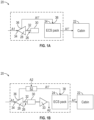
FIG. 1A is schematic diagram of an environmental control system of an aircraft according to an embodiment; -
FIG. 1B is schematic diagram of an environmental control system of an aircraft according to an embodiment; -
FIG. 2 is a schematic diagram of an environmental control pack of an aircraft according to an embodiment; -
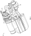
FIG. 3 is a perspective view of an environmental control system of a vehicle according to an embodiment; -
FIG. 4 is a detailed perspective view of a portion of the environmental control system ofFIG. 3 ; -
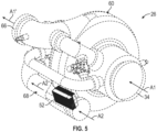
FIG. 5 is a perspective view of a heat exchanger associated with a portion of the environmental control system ofFIG. 4 according to an embodiment; -
FIG. 6 is a schematic cross-sectional diagram of the heat exchanger associated with a portion of the environmental control system according to an embodiment; and -
FIG. 7 is a detailed perspective view of the heat exchanger associated with a portion of the environmental control system according to an embodiment. - A detailed description of one or more embodiments of the disclosed apparatus and method are presented herein by way of exemplification and not limitation with reference to the Figures.
- With reference to
FIG. 1A , an environmental control system (ECS) 20 of a vehicle is operable to supply a conditioned air to one or more loads, such as acabin 22 of the vehicle, at a proper temperature and pressure. An ECS 20 typically includes a multitude of various components which are packaged relatively close together to define an environmentalcontrol system pack 24. As shown, in an embodiment, the ECS 20 may also include at least one cabin air compressor (CAC) 26 positioned upstream from theECS pack 24 relative to a flow of a first medium A1 through theECS 20. ACAC 26 includes acompressor 28 that is driven by another component. As shown inFIG. 1A , thecompressor 28 may be driven by amotor 30 operably coupled thereto. In the illustrated, non-limiting embodiment, themotor 30 is connected to thecompressor 28 by arotatable shaft 32. However, in other embodiments, such as shown inFIG. 1B , as an alternative to or in addition to themotor 30, the CAC 26 may include aturbine 33 operably coupled to thecompressor 28 via theshaft 32. In such embodiments, energy extracted from a second medium A2 within theturbine 33 may be used to drive thecompressor 28. - As shown, a first medium A1 is provided to an
inlet 34 of thecompressor 28. Within thecompressor 28, the flow of the first medium A1 is compressed, causing the temperature and pressure of the first medium A1 to increase. A compressed first medium A1' is output from anoutlet 36 of thecompressor 28 to aninlet 38 of theECS pack 24. The compressed first medium A1' may ultimately be provided to thecabin 22 of the vehicle, or alternatively, may be provided to another subsystem of the vehicle and/or exhausted overboard. - With reference now to
FIGS. 2 and3 , an example of anECS pack 24 is illustrated in more detail. It should be appreciated that theECS pack 24 may, but need not be used in combination with the one or more CACs 26 as previously described. As shown, theECS pack 24 may include athermodynamic device 40. Thethermodynamic device 40 is a mechanical device that includes components for performing thermodynamic work on a medium (e.g., extracts work from or applies work to the medium A by raising and/or lowering pressure and by raising and/or lowering temperature). Examples of athermodynamic device 40 include an air cycle machine, a two-wheel air cycle machine, a three-wheel air cycle machine, a four-wheel air cycle machine, etc. - As shown, the
thermodynamic device 40, also referred to herein as an air cycle machine, may include acompressor 42 and at least oneturbine 44 operably coupled by ashaft 46. In an embodiment, thethermodynamic device 40 includes a plurality of turbines, such as threeturbines turbines thermodynamic device 40 having threeturbines ECS pack 24 including athermodynamic device 40 having a single turbine, two turbines, or more than three turbines is also contemplated herein. - A
compressor 42 is a mechanical device configured to raise a pressure of a medium and can be driven by another mechanical device (e.g., a motor or a medium via a turbine). Examples of compressor types include centrifugal, diagonal or mixed-flow, axial-flow, reciprocating, ionic liquid piston, rotary screw, rotary vane, scroll, diaphragm, air bubble, etc. A turbine, such as any ofturbines compressor 42 via theshaft 46. - With continued reference to
FIG. 2 , in an embodiment, thecompressor 42 of thethermodynamic device 40 is configured to receive a first medium A1 whereas a second or different type of medium A2 may be provided to at least one of theturbines ECS 20 includes theCAC 26 and theECS pack 24 including thethermodynamic device 40, the compressed first medium A1' output from theCAC 26 may be the first medium A1 ultimately provided to thecompressor 42 of thethermodynamic device 40. - In an embodiment, such as where the
environmental control system 20 is used in an aircraft application, the first medium A1 is fresh air, such as outside air for example. The outside air can be procured via one or more scooping mechanisms, such as an impact scoop or a flush scoop for example. In an embodiment, the first medium A1 is ram air drawn from a portion of a ram air circuit. Generally, the fresh or outside air as described herein is at an ambient pressure equal to an air pressure outside of the aircraft when the aircraft is on the ground and is between an ambient pressure and a cabin pressure when the aircraft is in flight. However, embodiments where the first medium is air provided from another source, such as bleed air for example, are also within the scope of the disclosure. In the illustrated, non-limiting embodiment, the second type of medium A2 is provided from another source of the vehicle. For example, in an embodiment, the second medium A2 is cabin discharge air, which is air leaving thecabin 22 and that would typically be discharged overboard. - In some embodiments, a third medium A3 may be provided to another of the plurality of
turbines thermodynamic device 40. In such embodiments, the third medium A3 may be bleed air, which is pressurized air originating from, i.e., being "bled" from, an engine or auxiliary power unit of the aircraft. It shall be understood that one or more of the temperature, humidity, and pressure of the bleed air can vary based upon the compressor stage and revolutions per minute of the engine or auxiliary power unit from which the air is drawn. - Although not described herein, it should be understood that the
ECS pack 24 includes several other components including a ram air circuit having at least one ram air heat exchanger, and a water extractor. Further, theECS pack 24 illustrated and described herein is intended as an example only. Accordingly, anECS pack 24 with any suitable configuration is within contemplated herein. - To optimize the extraction of energy from the second medium A2 within the
turbine turbine turbine 33, 50 (seeFIG. 1B ). To heat the second medium A2 at or upstream from theturbine ECS 20, such as the compressed first medium A1'. In the illustrated, non-limiting embodiment ofFIGS. 1B and3-6 , the second medium A2 is arranged in a heat transfer relationship with the compressed first medium A1' generated by thecompressor 28 of theCAC 26. However, it should be understood that in other embodiments, the second medium A2 may be arranged in a heat transfer relationship with the compressed first medium A1' generated by thecompressor 42 of thethermodynamic device 40 of theECS pack 24. - The second medium A2 may be arranged in a heat transfer relationship with the compressed first medium A1' via a
heat exchanger 52. Theheat exchanger 52 may be fluidly connected to a portion of thecompressor 28 and to theconduit 68 configured to receive a flow of the second medium A2. In an embodiment, best shown inFIGS. 5 and6 , theheat exchanger 52 is mounted at or adjacent to thehousing 60 of the compressor, such ascompressor 28. In the illustrated, non-limiting embodiment, theheat exchanger 52 is positioned at or downstream from both the rotating portion (including the impeller) 62 and thevolute 64 of thecompressor 28 such that the flow provided to theheat exchanger 52 is compressed first medium A1' having an increased temperature and/or pressure relative to the first medium A1 provided to theinlet 34 of thecompressor 28. In other embodiments, theheat exchanger 52 may be located at any suitable location about thecompressor housing 60 between the outlet or downstream end of the rotatingportion 62 and theoutlet 66 of thecompressor housing 60. - In some embodiments, the
heat exchanger 52 is integrally formed with a portion of thecompressor housing 60 of thecompressor 28. In other embodiments, theheat exchanger 52 is permanently or removably coupled to thecompressor housing 60, such as via a plurality of fasteners for example. - With reference to
FIG. 7 , an example of theheat exchanger 52 is illustrated in more detail. In an embodiment, theheat exchanger 52 includes a centrally locatedplate 70. The centrally locatedplate 70 may form a portion of thecompressor housing 60, or alternatively or additionally, may form a portion of the wall of theconduit 68 through which a flow of the second medium A2 passes. Although theplate 70 is illustrated as having a planar configuration, it should be understood that in other embodiments theplate 70 may have another configuration. For example, at least afirst side 72 of theplate 70 may be curved in a manner complementary to the flow provided at the outlet of the rotatingportion 62, or to thevolute 64 of thecompressor housing 60. - In an embodiment, at least one
fin 74, such as a plurality of first fins for example, extends from afirst side 72 of theplate 70 into the interior of thecompressor housing 60. The plurality offirst fins 74 extending from theplate 70 may be used to define a plurality ofchannels 76 through which the compressed first medium A1' will flow. Although the plurality offirst fins 74 are illustrated as being generally rectangular in shape, it should be understood thatfirst fins 74 having another shape are also within the scope of the disclosure. For example, because of the circular flow of the compressed first medium A1' within a portion of thecompressor housing 60, thefirst fins 74 may have an arcuate contour complementary to the flow path. Furthermore, although each of the plurality offirst fins 74 is illustrated as being substantially identical, embodiments where a configuration of one or more of thefirst fins 74 varies relative to the remainder of the first fins are also within the scope of the disclosure. - Alternatively, or in addition, at least one
fin 78, such as a plurality of second fins for example, extend from asecond side 80 of theplate 70 into the flow path of the second medium A2 defined by the conduit. The plurality ofsecond fins 78 extending from theplate 70 may be used to define a plurality of channels 82 through which the cooler second medium A2 will flow. In the illustrated, non-limiting embodiment, the plurality ofsecond fins 78 may be oriented parallel to the flow of the second medium A2. However, embodiments where the channels 82 defined between thesecond fins 78 have a non-linear configuration, such as to increase the surface area and therefore the heat transfer at thesecond fins 78 is also within the scope of the disclosure. - In an embodiment, one or both of the plurality of first and/or
second fins heat exchanger 52. Alternatively, or in addition, the first and/or second plurality offins heat exchanger 52. - It should be understood that the
heat exchanger 52 illustrated and described herein is intended as an example only and that aheat exchanger 52 having another suitable configuration is also contemplated herein. Further, theheat exchanger 52 may be formed from a lightweight material, such as aluminum for example, via any of a number of manufacturing processes, including but not limited to casting, or additive manufacturing. - Integration of the
heat exchanger 52, such as used to heat a flow of medium to be provided to the power turbine of an air cycle machine for example, into thecompressor housing 60 reduces the complexity of theECS 20 as well as the overall installed system volume and weight. Further, such a configuration eliminates the need for a hot or high-pressure side ducting, coupling, and header. - The term "about" is intended to include the degree of error associated with measurement of the particular quantity based upon the equipment available at the time of filing the application.
- The terminology used herein is for the purpose of describing particular embodiments only and is not intended to be limiting of the present disclosure. As used herein, the singular forms "a", "an" and "the" are intended to include the plural forms as well, unless the context clearly indicates otherwise. It will be further understood that the terms "comprises" and/or "comprising," when used in this specification, specify the presence of stated features, integers, steps, operations, elements, and/or components, but do not preclude the presence or addition of one or more other features, integers, steps, operations, element components, and/or groups thereof.
- While the present disclosure has been described with reference to an exemplary embodiment or embodiments, it will be understood by those skilled in the art that various changes may be made and equivalents may be substituted for elements thereof without departing from the scope of the present disclosure. In addition, many modifications may be made to adapt a particular situation or material to the teachings of the present disclosure without departing from the essential scope thereof. Therefore, it is intended that the present disclosure not be limited to the particular embodiment disclosed as the best mode contemplated for carrying out this present disclosure, but that the present disclosure will include all embodiments falling within the scope of the claims.
Claims (15)
- An environmental control system of a vehicle comprising:a compressor (28) having a compressor inlet configured to receive a first medium and a compressor outlet, wherein a compressed first medium is provided at the compressor outlet;a conduit (68) configured to receive a second medium; anda heat exchanger (52) mounted to the compressor, wherein the heat exchanger is fluidly connected to a portion of the compressor and to the conduit.
- The environmental control system of claim 1, wherein the compressor further comprises a compressor housing (60), the heat exchanger being mounted to the compressor housing.
- The environmental control system of claim 2, wherein the heat exchanger (52) is integrally formed with the compressor housing.
- The environmental control system of claim 2, wherein the compressor further comprises a rotating portion (62) arranged within the compressor housing, the heat exchanger being mounted to the compressor between the rotating portion and an outlet (66) of the compressor.
- The environmental control system of claim 2, wherein the compressor further comprises a volute (64) formed within the compressor housing, the heat exchanger being mounted to the compressor between the volute and an outlet of the compressor.
- The environmental control system of claim 2, wherein the heat exchanger (52) further comprises a plate (70) and at least one fin (74) extending from the plate.
- The environmental control system of claim 6, wherein the at least one fin (74) includes a plurality of first fins, the plurality of first fins being arranged within the compressor housing, and preferably wherein the at least one fin further comprises a plurality of second fins, the plurality of second fins being arranged within the conduit.
- The environmental control system of claim 6, wherein the at least one fin includes a plurality of second fins, the plurality of second fins being arranged within the conduit.
- The environmental control system of any preceding claim, wherein the compressor is part of a cabin air compressor; or
wherein the compressor is part of a thermodynamic device. - The environmental control system of any preceding claim, wherein the first medium is fresh air; and/or
wherein the second medium is cabin air. - The environmental control system of any preceding claim, wherein the vehicle is an aircraft.
- A method of operating an environmental control system of a vehicle comprising:compressing a first medium at a compressor to form a compressed first medium;extracting energy from a second medium at a turbine; andheating the second medium within a heat exchanger using the compressed first medium, wherein heating the second medium occurs prior to the extracting energy from the second medium.
- The method of claim 12, wherein the first medium is fresh air; and/or
wherein the second medium is cabin air. - The method of claim 12 or 13, further comprising providing the compressed first medium to an environmental control system pack, the environmental control system pack being located downstream from the compressor relative to a flow of the first medium.
- The method of any of claims 12-14, further comprising providing the first medium to an environmental control system pack, wherein the compressor is part of the environmental control system pack; and/or
wherein the vehicle is an aircraft.
Applications Claiming Priority (2)
| Application Number | Priority Date | Filing Date | Title |
|---|---|---|---|
| US202263351090P | 2022-06-10 | 2022-06-10 | |
| US17/946,655 US12479581B2 (en) | 2022-06-10 | 2022-09-16 | Cabin air compressor with integral heat exchanger |
Publications (2)
| Publication Number | Publication Date |
|---|---|
| EP4289744A1 true EP4289744A1 (en) | 2023-12-13 |
| EP4289744B1 EP4289744B1 (en) | 2025-09-10 |
Family
ID=86693198
Family Applications (1)
| Application Number | Title | Priority Date | Filing Date |
|---|---|---|---|
| EP23177381.3A Active EP4289744B1 (en) | 2022-06-10 | 2023-06-05 | Cabin air compressor with integral heat exchanger |
Country Status (2)
| Country | Link |
|---|---|
| US (1) | US12479581B2 (en) |
| EP (1) | EP4289744B1 (en) |
Cited By (1)
| Publication number | Priority date | Publication date | Assignee | Title |
|---|---|---|---|---|
| US20260028126A1 (en) * | 2024-07-29 | 2026-01-29 | Hamilton Sundstrand Corporation | Additively manufactured heat exchanger and diffuser pipe coupled to a compressor stage |
Families Citing this family (1)
| Publication number | Priority date | Publication date | Assignee | Title |
|---|---|---|---|---|
| US12395044B2 (en) * | 2023-02-14 | 2025-08-19 | Hamilton Sundstrand Corporation | CAC motor auxiliary water cooling system |
Citations (4)
| Publication number | Priority date | Publication date | Assignee | Title |
|---|---|---|---|---|
| GB831742A (en) * | 1956-06-11 | 1960-03-30 | Rolls Royce | Improvements in or relating to aircraft |
| US20180370636A1 (en) * | 2017-06-23 | 2018-12-27 | Liebherr-Aerospace Toulouse Sas | Aircraft cabin environmental control system and method and aircraft equipped with such control system |
| KR102099423B1 (en) * | 2018-11-06 | 2020-04-09 | 한국항공우주연구원 | Compressor formed integrally with intercooler part and overload multi-stage propulsion system comprising the same |
| US11084592B2 (en) * | 2018-06-26 | 2021-08-10 | Hamilton Sundstrand Corporation | Aircraft environmental control system |
Family Cites Families (10)
| Publication number | Priority date | Publication date | Assignee | Title |
|---|---|---|---|---|
| US2958211A (en) | 1956-06-11 | 1960-11-01 | Rolls Royce | Cabin air supply means for aircraft |
| US6681592B1 (en) * | 2001-02-16 | 2004-01-27 | Hamilton Sundstrand Corporation | Electrically driven aircraft cabin ventilation and environmental control system |
| GB2499577A (en) * | 2011-11-29 | 2013-08-28 | Eaton Aerospace Ltd | Aircraft on board inert gas generation system |
| US9669936B1 (en) | 2012-10-24 | 2017-06-06 | The Boeing Company | Aircraft air conditioning systems and methods |
| US9598175B2 (en) * | 2015-04-24 | 2017-03-21 | Hamilton Sundstrand Corporation | Modular environmental air conditioning system |
| US10533784B2 (en) * | 2016-03-16 | 2020-01-14 | Hamilton Sundstrand Corporation | Pack-and-A-half architecture for environmental control systems |
| US10843804B2 (en) * | 2017-08-01 | 2020-11-24 | Honeywell International Inc. | Cabin outflow air energy optimized cabin pressurizing system |
| DE112018005188T5 (en) * | 2017-11-01 | 2020-06-25 | Ihi Corporation | Centrifugal compressor |
| US10934007B2 (en) * | 2018-07-06 | 2021-03-02 | Hamilton Sunstrand Corporation | Pressure optimized sourcing of cabin pressurization and component air cooling |
| US20210053687A1 (en) * | 2019-08-20 | 2021-02-25 | Hamilton Sundstrand Corporation | Air conditioning system with integrated cabin pressure control |
-
2022
- 2022-09-16 US US17/946,655 patent/US12479581B2/en active Active
-
2023
- 2023-06-05 EP EP23177381.3A patent/EP4289744B1/en active Active
Patent Citations (4)
| Publication number | Priority date | Publication date | Assignee | Title |
|---|---|---|---|---|
| GB831742A (en) * | 1956-06-11 | 1960-03-30 | Rolls Royce | Improvements in or relating to aircraft |
| US20180370636A1 (en) * | 2017-06-23 | 2018-12-27 | Liebherr-Aerospace Toulouse Sas | Aircraft cabin environmental control system and method and aircraft equipped with such control system |
| US11084592B2 (en) * | 2018-06-26 | 2021-08-10 | Hamilton Sundstrand Corporation | Aircraft environmental control system |
| KR102099423B1 (en) * | 2018-11-06 | 2020-04-09 | 한국항공우주연구원 | Compressor formed integrally with intercooler part and overload multi-stage propulsion system comprising the same |
Cited By (1)
| Publication number | Priority date | Publication date | Assignee | Title |
|---|---|---|---|---|
| US20260028126A1 (en) * | 2024-07-29 | 2026-01-29 | Hamilton Sundstrand Corporation | Additively manufactured heat exchanger and diffuser pipe coupled to a compressor stage |
Also Published As
| Publication number | Publication date |
|---|---|
| US12479581B2 (en) | 2025-11-25 |
| US20230399112A1 (en) | 2023-12-14 |
| EP4289744B1 (en) | 2025-09-10 |
Similar Documents
| Publication | Publication Date | Title |
|---|---|---|
| EP3945023B1 (en) | Aircraft environmental control system | |
| EP3489142B1 (en) | Aircraft environmental control system with series bleed air turbines | |
| EP3514065B1 (en) | Aircraft environmental control system | |
| EP3354573B1 (en) | Environmental control system in an integrated pack arrangement with one bleed/outflow heat exchanger | |
| EP3945026A1 (en) | Aircraft environmental control system | |
| EP4289744B1 (en) | Cabin air compressor with integral heat exchanger | |
| US12410949B2 (en) | Ram air turbine powered cabin air compressor | |
| EP3882153B1 (en) | Fresh air ecs | |
| US12162607B2 (en) | Environmental control system for supersonic commercial aircraft | |
| US20240410625A1 (en) | Regeneration using liquid loop of environmental control system | |
| EP4331991A1 (en) | Environmental control system with low inlet pressure | |
| US12078379B2 (en) | Split regeneration environmental control system | |
| US20250334354A1 (en) | Contoured inlet manifold for subfreezing heat exchanger | |
| EP4520664A1 (en) | Less bleed environmental control system | |
| EP4495005A1 (en) | Environmental control system with adaptive turbine arrangement | |
| US12595978B2 (en) | Drain system for ECS water collection | |
| US12234018B2 (en) | Environmental control system with no bleed driven throttle | |
| US20250305707A1 (en) | Bleedless environmental control system |
Legal Events
| Date | Code | Title | Description |
|---|---|---|---|
| PUAI | Public reference made under article 153(3) epc to a published international application that has entered the european phase |
Free format text: ORIGINAL CODE: 0009012 |
|
| STAA | Information on the status of an ep patent application or granted ep patent |
Free format text: STATUS: THE APPLICATION HAS BEEN PUBLISHED |
|
| AK | Designated contracting states |
Kind code of ref document: A1 Designated state(s): AL AT BE BG CH CY CZ DE DK EE ES FI FR GB GR HR HU IE IS IT LI LT LU LV MC ME MK MT NL NO PL PT RO RS SE SI SK SM TR |
|
| STAA | Information on the status of an ep patent application or granted ep patent |
Free format text: STATUS: REQUEST FOR EXAMINATION WAS MADE |
|
| 17P | Request for examination filed |
Effective date: 20240612 |
|
| RBV | Designated contracting states (corrected) |
Designated state(s): AL AT BE BG CH CY CZ DE DK EE ES FI FR GB GR HR HU IE IS IT LI LT LU LV MC ME MK MT NL NO PL PT RO RS SE SI SK SM TR |
|
| GRAP | Despatch of communication of intention to grant a patent |
Free format text: ORIGINAL CODE: EPIDOSNIGR1 |
|
| STAA | Information on the status of an ep patent application or granted ep patent |
Free format text: STATUS: GRANT OF PATENT IS INTENDED |
|
| INTG | Intention to grant announced |
Effective date: 20250408 |
|
| GRAS | Grant fee paid |
Free format text: ORIGINAL CODE: EPIDOSNIGR3 |
|
| GRAA | (expected) grant |
Free format text: ORIGINAL CODE: 0009210 |
|
| STAA | Information on the status of an ep patent application or granted ep patent |
Free format text: STATUS: THE PATENT HAS BEEN GRANTED |
|
| AK | Designated contracting states |
Kind code of ref document: B1 Designated state(s): AL AT BE BG CH CY CZ DE DK EE ES FI FR GB GR HR HU IE IS IT LI LT LU LV MC ME MK MT NL NO PL PT RO RS SE SI SK SM TR |
|
| REG | Reference to a national code |
Ref country code: GB Ref legal event code: FG4D |
|
| REG | Reference to a national code |
Ref country code: CH Ref legal event code: EP |
|
| REG | Reference to a national code |
Ref country code: DE Ref legal event code: R096 Ref document number: 602023006491 Country of ref document: DE |
|
| REG | Reference to a national code |
Ref country code: IE Ref legal event code: FG4D |
|
| PG25 | Lapsed in a contracting state [announced via postgrant information from national office to epo] |
Ref country code: NO Free format text: LAPSE BECAUSE OF FAILURE TO SUBMIT A TRANSLATION OF THE DESCRIPTION OR TO PAY THE FEE WITHIN THE PRESCRIBED TIME-LIMIT Effective date: 20251210 |
|
| REG | Reference to a national code |
Ref country code: LT Ref legal event code: MG9D |
|
| PG25 | Lapsed in a contracting state [announced via postgrant information from national office to epo] |
Ref country code: FI Free format text: LAPSE BECAUSE OF FAILURE TO SUBMIT A TRANSLATION OF THE DESCRIPTION OR TO PAY THE FEE WITHIN THE PRESCRIBED TIME-LIMIT Effective date: 20250910 |
|
| REG | Reference to a national code |
Ref country code: NL Ref legal event code: MP Effective date: 20250910 |
|
| PG25 | Lapsed in a contracting state [announced via postgrant information from national office to epo] |
Ref country code: HR Free format text: LAPSE BECAUSE OF FAILURE TO SUBMIT A TRANSLATION OF THE DESCRIPTION OR TO PAY THE FEE WITHIN THE PRESCRIBED TIME-LIMIT Effective date: 20250910 |
|
| PG25 | Lapsed in a contracting state [announced via postgrant information from national office to epo] |
Ref country code: GR Free format text: LAPSE BECAUSE OF FAILURE TO SUBMIT A TRANSLATION OF THE DESCRIPTION OR TO PAY THE FEE WITHIN THE PRESCRIBED TIME-LIMIT Effective date: 20251211 |
|
| PG25 | Lapsed in a contracting state [announced via postgrant information from national office to epo] |
Ref country code: SE Free format text: LAPSE BECAUSE OF FAILURE TO SUBMIT A TRANSLATION OF THE DESCRIPTION OR TO PAY THE FEE WITHIN THE PRESCRIBED TIME-LIMIT Effective date: 20250910 |
|
| PG25 | Lapsed in a contracting state [announced via postgrant information from national office to epo] |
Ref country code: LV Free format text: LAPSE BECAUSE OF FAILURE TO SUBMIT A TRANSLATION OF THE DESCRIPTION OR TO PAY THE FEE WITHIN THE PRESCRIBED TIME-LIMIT Effective date: 20250910 |
|
| PG25 | Lapsed in a contracting state [announced via postgrant information from national office to epo] |
Ref country code: PL Free format text: LAPSE BECAUSE OF FAILURE TO SUBMIT A TRANSLATION OF THE DESCRIPTION OR TO PAY THE FEE WITHIN THE PRESCRIBED TIME-LIMIT Effective date: 20250910 Ref country code: BG Free format text: LAPSE BECAUSE OF FAILURE TO SUBMIT A TRANSLATION OF THE DESCRIPTION OR TO PAY THE FEE WITHIN THE PRESCRIBED TIME-LIMIT Effective date: 20250910 |
|
| PG25 | Lapsed in a contracting state [announced via postgrant information from national office to epo] |
Ref country code: RS Free format text: LAPSE BECAUSE OF FAILURE TO SUBMIT A TRANSLATION OF THE DESCRIPTION OR TO PAY THE FEE WITHIN THE PRESCRIBED TIME-LIMIT Effective date: 20251210 |
|
| PG25 | Lapsed in a contracting state [announced via postgrant information from national office to epo] |
Ref country code: ES Free format text: LAPSE BECAUSE OF FAILURE TO SUBMIT A TRANSLATION OF THE DESCRIPTION OR TO PAY THE FEE WITHIN THE PRESCRIBED TIME-LIMIT Effective date: 20250910 |
|
| REG | Reference to a national code |
Ref country code: AT Ref legal event code: MK05 Ref document number: 1835671 Country of ref document: AT Kind code of ref document: T Effective date: 20250910 |
|
| PG25 | Lapsed in a contracting state [announced via postgrant information from national office to epo] |
Ref country code: NL Free format text: LAPSE BECAUSE OF FAILURE TO SUBMIT A TRANSLATION OF THE DESCRIPTION OR TO PAY THE FEE WITHIN THE PRESCRIBED TIME-LIMIT Effective date: 20250910 |
|
| PG25 | Lapsed in a contracting state [announced via postgrant information from national office to epo] |
Ref country code: SM Free format text: LAPSE BECAUSE OF FAILURE TO SUBMIT A TRANSLATION OF THE DESCRIPTION OR TO PAY THE FEE WITHIN THE PRESCRIBED TIME-LIMIT Effective date: 20250910 |
|
| PG25 | Lapsed in a contracting state [announced via postgrant information from national office to epo] |
Ref country code: AT Free format text: LAPSE BECAUSE OF FAILURE TO SUBMIT A TRANSLATION OF THE DESCRIPTION OR TO PAY THE FEE WITHIN THE PRESCRIBED TIME-LIMIT Effective date: 20250910 |
|
| PG25 | Lapsed in a contracting state [announced via postgrant information from national office to epo] |
Ref country code: IT Free format text: LAPSE BECAUSE OF FAILURE TO SUBMIT A TRANSLATION OF THE DESCRIPTION OR TO PAY THE FEE WITHIN THE PRESCRIBED TIME-LIMIT Effective date: 20250910 |
|
| PG25 | Lapsed in a contracting state [announced via postgrant information from national office to epo] |
Ref country code: IS Free format text: LAPSE BECAUSE OF FAILURE TO SUBMIT A TRANSLATION OF THE DESCRIPTION OR TO PAY THE FEE WITHIN THE PRESCRIBED TIME-LIMIT Effective date: 20260110 |
|
| PG25 | Lapsed in a contracting state [announced via postgrant information from national office to epo] |
Ref country code: PT Free format text: LAPSE BECAUSE OF FAILURE TO SUBMIT A TRANSLATION OF THE DESCRIPTION OR TO PAY THE FEE WITHIN THE PRESCRIBED TIME-LIMIT Effective date: 20260112 Ref country code: CZ Free format text: LAPSE BECAUSE OF FAILURE TO SUBMIT A TRANSLATION OF THE DESCRIPTION OR TO PAY THE FEE WITHIN THE PRESCRIBED TIME-LIMIT Effective date: 20250910 |
|
| PG25 | Lapsed in a contracting state [announced via postgrant information from national office to epo] |
Ref country code: EE Free format text: LAPSE BECAUSE OF FAILURE TO SUBMIT A TRANSLATION OF THE DESCRIPTION OR TO PAY THE FEE WITHIN THE PRESCRIBED TIME-LIMIT Effective date: 20250910 Ref country code: SK Free format text: LAPSE BECAUSE OF FAILURE TO SUBMIT A TRANSLATION OF THE DESCRIPTION OR TO PAY THE FEE WITHIN THE PRESCRIBED TIME-LIMIT Effective date: 20250910 |