EP4289680A1 - Igniter assembly and gas generator - Google Patents
Igniter assembly and gas generator Download PDFInfo
- Publication number
- EP4289680A1 EP4289680A1 EP22749667.6A EP22749667A EP4289680A1 EP 4289680 A1 EP4289680 A1 EP 4289680A1 EP 22749667 A EP22749667 A EP 22749667A EP 4289680 A1 EP4289680 A1 EP 4289680A1
- Authority
- EP
- European Patent Office
- Prior art keywords
- wall portion
- igniter
- region portion
- outer peripheral
- central region
- Prior art date
- Legal status (The legal status is an assumption and is not a legal conclusion. Google has not performed a legal analysis and makes no representation as to the accuracy of the status listed.)
- Pending
Links
Images



Classifications
-
- B—PERFORMING OPERATIONS; TRANSPORTING
- B60—VEHICLES IN GENERAL
- B60R—VEHICLES, VEHICLE FITTINGS, OR VEHICLE PARTS, NOT OTHERWISE PROVIDED FOR
- B60R21/00—Arrangements or fittings on vehicles for protecting or preventing injuries to occupants or pedestrians in case of accidents or other traffic risks
- B60R21/02—Occupant safety arrangements or fittings, e.g. crash pads
- B60R21/16—Inflatable occupant restraints or confinements designed to inflate upon impact or impending impact, e.g. air bags
- B60R21/26—Inflatable occupant restraints or confinements designed to inflate upon impact or impending impact, e.g. air bags characterised by the inflation fluid source or means to control inflation fluid flow
- B60R21/268—Inflatable occupant restraints or confinements designed to inflate upon impact or impending impact, e.g. air bags characterised by the inflation fluid source or means to control inflation fluid flow using instantaneous release of stored pressurised gas
- B60R21/274—Inflatable occupant restraints or confinements designed to inflate upon impact or impending impact, e.g. air bags characterised by the inflation fluid source or means to control inflation fluid flow using instantaneous release of stored pressurised gas characterised by means to rupture or open the fluid source
-
- B—PERFORMING OPERATIONS; TRANSPORTING
- B60—VEHICLES IN GENERAL
- B60R—VEHICLES, VEHICLE FITTINGS, OR VEHICLE PARTS, NOT OTHERWISE PROVIDED FOR
- B60R21/00—Arrangements or fittings on vehicles for protecting or preventing injuries to occupants or pedestrians in case of accidents or other traffic risks
- B60R21/02—Occupant safety arrangements or fittings, e.g. crash pads
- B60R21/16—Inflatable occupant restraints or confinements designed to inflate upon impact or impending impact, e.g. air bags
- B60R21/26—Inflatable occupant restraints or confinements designed to inflate upon impact or impending impact, e.g. air bags characterised by the inflation fluid source or means to control inflation fluid flow
- B60R21/264—Inflatable occupant restraints or confinements designed to inflate upon impact or impending impact, e.g. air bags characterised by the inflation fluid source or means to control inflation fluid flow using instantaneous generation of gas, e.g. pyrotechnic
- B60R21/2644—Inflatable occupant restraints or confinements designed to inflate upon impact or impending impact, e.g. air bags characterised by the inflation fluid source or means to control inflation fluid flow using instantaneous generation of gas, e.g. pyrotechnic using only solid reacting substances, e.g. pellets, powder
-
- F—MECHANICAL ENGINEERING; LIGHTING; HEATING; WEAPONS; BLASTING
- F42—AMMUNITION; BLASTING
- F42B—EXPLOSIVE CHARGES, e.g. FOR BLASTING, FIREWORKS, AMMUNITION
- F42B3/00—Blasting cartridges, i.e. case and explosive
- F42B3/04—Blasting cartridges, i.e. case and explosive for producing gas under pressure
-
- F—MECHANICAL ENGINEERING; LIGHTING; HEATING; WEAPONS; BLASTING
- F42—AMMUNITION; BLASTING
- F42B—EXPLOSIVE CHARGES, e.g. FOR BLASTING, FIREWORKS, AMMUNITION
- F42B3/00—Blasting cartridges, i.e. case and explosive
- F42B3/10—Initiators therefor
- F42B3/103—Mounting initiator heads in initiators; Sealing-plugs
-
- F—MECHANICAL ENGINEERING; LIGHTING; HEATING; WEAPONS; BLASTING
- F42—AMMUNITION; BLASTING
- F42B—EXPLOSIVE CHARGES, e.g. FOR BLASTING, FIREWORKS, AMMUNITION
- F42B3/00—Blasting cartridges, i.e. case and explosive
- F42B3/10—Initiators therefor
- F42B3/12—Bridge initiators
- F42B3/125—Bridge initiators characterised by the configuration of the bridge initiator case
-
- F—MECHANICAL ENGINEERING; LIGHTING; HEATING; WEAPONS; BLASTING
- F42—AMMUNITION; BLASTING
- F42B—EXPLOSIVE CHARGES, e.g. FOR BLASTING, FIREWORKS, AMMUNITION
- F42B3/00—Blasting cartridges, i.e. case and explosive
- F42B3/10—Initiators therefor
- F42B3/12—Bridge initiators
- F42B3/125—Bridge initiators characterised by the configuration of the bridge initiator case
- F42B3/127—Bridge initiators characterised by the configuration of the bridge initiator case the case having burst direction defining elements
-
- B—PERFORMING OPERATIONS; TRANSPORTING
- B60—VEHICLES IN GENERAL
- B60R—VEHICLES, VEHICLE FITTINGS, OR VEHICLE PARTS, NOT OTHERWISE PROVIDED FOR
- B60R21/00—Arrangements or fittings on vehicles for protecting or preventing injuries to occupants or pedestrians in case of accidents or other traffic risks
- B60R21/02—Occupant safety arrangements or fittings, e.g. crash pads
- B60R21/16—Inflatable occupant restraints or confinements designed to inflate upon impact or impending impact, e.g. air bags
- B60R21/26—Inflatable occupant restraints or confinements designed to inflate upon impact or impending impact, e.g. air bags characterised by the inflation fluid source or means to control inflation fluid flow
- B60R2021/26029—Ignitors
Definitions
- the present invention relates to an igniter assembly and a gas generator including the igniter assembly.
- An igniter is used as a starting device of a gas generator for an airbag or a gas generator for a seat belt retractor, and mainly an electric igniter is widely known which is operated by an ignition current.
- an igniter assembly is known in which an igniter is attached via a resin to a tubular member provided in a housing.
- an attachment portion having a tubular shape and attached with the igniter is formed at the central portion of the bottom plate of the housing, and the igniter is fixed to the attachment portion by a resin provided between the igniter and the attachment portion.
- This resin further forms a peripheral wall portion surrounding the igniter, and a space inside the peripheral wall portion is filled with a gas generating agent of which combustion is caused by operation of the igniter.
- a space into which a connector for supplying a current to the igniter is inserted is formed on the other end side of the attachment portion.
- a container made of metal and accommodating an ignition charge is ruptured to emit flame.
- a peripheral wall portion made of resin surrounds the igniter
- the peripheral wall portion may be deformed by a load acting on the peripheral wall portion, and the peripheral wall portion may have a crack or damage.
- the holding of the igniter becomes insufficient or the sealability as the gas generator is impaired.
- the technology of the present disclosure has been made in view of the above problem, and an object is to provide a technology that can inhibit a large load from acting on a peripheral wall portion, made of resin, by a lid wall portion of a cup body ruptured when an igniter is operated in an igniter assembly having the structure where the peripheral wall portion surrounds the igniter.
- the technology of the present disclosure is an igniter assembly, including: an igniter including a container made of metal and an ignition charge, the igniter being configured to emit a combustion product of the ignition charge to an outside of the container when a lid wall portion is ruptured when the igniter is operated, the container including a peripheral wall portion having a tubular shape and the lid wall portion configured to close one end portion of the peripheral wall portion, the ignition charge being filled in an accommodating space defined by the peripheral wall portion and the lid wall portion; and a tubular wall portion made of resin and formed in a tubular shape in a manner that the peripheral wall portion is surrounded, the tubular wall portion inwardly forming an emitting space in which the combustion product of the ignition charge is emitted.
- the lid wall portion includes an annular outer peripheral region portion disposed inside the peripheral wall portion in a radial direction of the peripheral wall portion, and a central region portion positioned inside the outer peripheral region portion in a radial direction, and the outer peripheral region portion is formed thicker than the central region portion.
- the lid wall portion When the igniter is operated, the lid wall portion is deformed and opens on the emitting space side from one end portion of the peripheral wall portion as a starting point by the combustion pressure of the ignition charge.
- the outer peripheral region portion since the outer peripheral region portion is formed thicker than the central region portion, the outer peripheral region portion has higher rigidity than a central region portion 122 and is less likely to be deformed.
- the lid wall portion is inhibited from largely opening.
- the ruptured lid wall portion is inhibited from coming into strong contact with the tubular wall portion.
- the ruptured lid wall portion does not come into contact with the tubular wall portion, or even if coming into contact, a large load does not occur.
- the igniter assembly according to the present disclosure it is possible to inhibit a large load from acting on the tubular wall portion due to the lid wall portion ruptured when the igniter is operated, the occurrence of a crack or damage in the tubular wall portion can be suppressed.
- the outer peripheral region portion and the central region portion may be connected in such a manner that an emitting surface facing the emitting space in the lid wall portion is recessed in the central region portion.
- the central region may include a plurality of grooves extending radially from a central portion of the central region portion as a starting point.
- a distance in the radial direction from the central portion of the central region portion to the outer peripheral region portion may be 1/2 or less of a distance in the radial direction from the central portion to the tubular wall portion.
- the emitting space may be filled with a first gas generating agent to be ignited by a combustion product of the ignition charge.
- the technology of the present disclosure may be a gas generator including: the igniter assembly described above; a housing attached with the igniter assembly; a combustion chamber formed inside the housing and filled with a second gas generating agent of which combustion is caused by operation of the igniter; and a gas discharge port formed at the housing and allowing the combustion chamber and an external space of the housing to communicate with each other.
- the gas generating agent of the present disclosure includes a gas generating agent that generates a combustion gas for inflating an airbag, and a transfer charge for causing combustion of the gas generating agent.
- FIG. 1 is a cross-sectional view of a gas generator for an airbag (hereinafter simply referred to as a gas generator) 100 including an igniter assembly X1 according to the first embodiment.
- FIG. 1 illustrates a state before the igniter indicated by reference sign 40 is operated.
- the gas generator 100 is configured as a so-called single type gas generator including one igniter. As illustrated in FIG.
- the gas generator 100 includes a housing 10, an igniter 40, a holding part 50, a tubular wall portion 60, a lid member 70, a spring member SP1, and a filter F1.
- the gas generator 100 is configured to cause combustion of a first gas generating agent 110 and a second gas generating agent 120 filled in the housing 10 by operating the igniter 40 disposed in the housing 10, and to inflate an airbag (not illustrated) by emitting a combustion gas that is a combustion product to the outside of the housing 10.
- an airbag not illustrated
- the housing 10 is formed in a short tubular shape in which both ends in the axial direction are closed by joining, in a state where the opening ends face each other, an upper shell 20 and a lower shell 30 made of metal and each formed in a bottomed tubular shape.
- the configuration of the upper shell 20 and the lower shell 30 are not limited to this, and a known configuration can be appropriately used.
- a direction along the axial direction of the housing 10 is defined as an up-down direction of the gas generator 100
- the upper shell 20 side that is, the upper side in FIG. 1
- the lower shell 30 side that is, the lower side in FIG. 1
- a lower side of the gas generator 100 is defined as a lower side of the gas generator 100.
- the upper shell 20 includes an upper tube portion 201 having a tubular shape, a top plate portion 202 that closes an upper end of the upper tube portion 201, and a joint portion 203 extending radially outward from a lower end portion of the upper tube portion 201.
- the lower shell 30 includes a lower tube portion 301 having a tubular shape, a bottom plate portion 302 that closes a lower end of the lower tube portion 301, and a joint portion 303 extending radially outward from an upper end portion of the lower tube portion 301.
- the joint portion 203 of the upper shell 20 and the joint portion 303 of the lower shell 30 are overlapped and joined by laser welding or the like to form the housing 10.
- a plurality of gas discharge ports 102 allowing the inside and the outside of the housing 10 to communicate with each other are formed side by side along the circumferential direction. Before the igniter 40 is operated, the gas discharge port 102 is closed by a seal tape not illustrated.
- the lower shell 30 of the housing 10 is provided with an attachment portion 304 attached with the igniter 40.
- the attachment portion 304 is formed integrally with the bottom plate portion 302. That is, the attachment portion 304 made of metal is formed by a part of the housing 10.
- the attachment portion 304 is formed in a substantially tubular shape with a part of the lower shell 30 protruding upward from the bottom plate portion 302.
- the upper end portion of the attachment portion 304 includes an attachment hole 304a through which a pair of conductive pins 4 of the igniter 40 is inserted.
- the igniter assembly X1 according to the first embodiment includes the igniter 40, the attachment portion 304, the holding part 50, the tubular wall portion 60, and the lid member 70.
- FIG. 2 is a cross-sectional view of the igniter assembly X1 according to the first embodiment.
- FIG. 2 illustrates a state before the igniter 40 is operated.
- the igniter 40 includes a cup body 1 which is made of metal and is an example of the "container" of the present disclosure, a metal header 2, an ignition charge 3, and the pair of conductive pins 4 (41 and 42).
- the cup body 1 is formed of a metal material in a bottomed tubular shape, and includes a tubular peripheral wall portion 11 and a lid wall portion 12 that closes one end portion (upper end portion) of the peripheral wall portion 11.
- the metal material forming the cup body 1 is not particularly limited, and examples thereof include stainless steel, aluminum, and iron.
- the metal header 2 is a closing member formed of a metal material in a circular columnar shape, is disposed inside the cup body 1, and closes an opening formed in the other end portion (lower end portion) of the peripheral wall portion 11.
- the metal header 2 is welded to an inner wall of the peripheral wall portion 11 on the outer peripheral surface thereof.
- the metal header 2 is disposed inside the cup body 1 and closes the opening of the peripheral wall portion 11, whereby the peripheral wall portion 11 of the cup body 1 includes, in the axial direction thereof, a contact region A1 in contact with the peripheral wall portion 11 and a non-contact region A2 that is a region on the lid wall portion 12 side relative to the contact region A1 and is not in contact with the metal header 2.
- the non-contact region A2 of the peripheral wall portion 11, the lid wall portion 12, and the metal header 2 define an accommodating space 401, which is a space filled with the ignition charge 3.
- the pair of conductive pins 4 extends downward from the metal header 2.
- a connector (not illustrated) for supplying electric power from an external power supply is connected to the pair of conductive pins 4.
- the igniter 40 is operated by electric power supplied to each of the conductive pins 4 via the connector, and ignites the ignition charge 3 filled in the accommodating space 401.
- the lid wall portion 12 of the cup body 1 is ruptured by the combustion pressure of the ignition charge 3, the combustion product of the ignition charge 3 is emitted to the outside of the cup body 1.
- the holding part 50 is formed of a resin material, and is provided between the igniter 40 and the attachment portion 304 to fix the igniter 40 to the attachment portion 304. At this time, as illustrated in FIG. 2 , the holding part 50 holds the igniter 40 in a state where the cup body 1 and the metal header 2 are positioned in the housing 10, the pair of conductive pins 4 is inserted into the attachment hole 304a, and the tips thereof are positioned outside the housing 10.
- the holding part 50 covers the contact region A1 of the peripheral wall portion 11, the metal header 2, and the attachment portion 304 to fix the igniter 40 to the attachment portion 304, and closes the attachment hole 304a to maintain airtightness in the housing 10.
- the holding part 50 forms, inside the attachment portion 304, a connector insertion space 501 into which the connector for supplying electric power to the conductive pins 4 can be inserted.
- the holding part 50 holds the igniter 40 in such a manner that the non-contact region A2 of the peripheral wall portion 11 and the lid wall portion 12 are exposed in an emitting space 601 described below, and the lower end of the pair of conductive pins 4 is exposed in the connector insertion space 501.
- the insulating property between the pair of conductive pins 4 is maintained by covering a part of the pair of conductive pins 4 with the holding part 50.
- the tubular wall portion 60 is formed in a tubular shape by a resin material, surrounds the peripheral wall portion 11 (more specifically, the non-contact region A2 of the peripheral wall portion 11) of the cup body 1, and extends upward from the holding part 50.
- the emitting space 601 which is a space where a combustion product of the ignition charge 3 is emitted, is formed inside the tubular wall portion 60.
- the emitting space 601 is filled with the first gas generating agent 110of which combustion is caused by operation of the igniter 40.
- the first gas generating agent 110 is ignited by the combustion product of the ignition charge 3 emitted by operation of the igniter 40 and generates a combustion gas.
- the holding part 50 and the tubular wall portion 60 are integrally formed as one member and are continuous with each other.
- a plurality of communication holes 602 allowing the inside and the outside of the emitting space 601 to communicate with each other are formed side by side along the circumferential direction.
- the holding part 50 and the tubular wall portion 60 are integrally formed by injection-molding a resin material in a manufacturing process of the igniter assembly X1.
- a resin material having excellent heat resistance, durability, corrosion resistance, and the like after curing can be suitably used.
- resin material include: thermoplastic resins such as polybutylene terephthalate resin, polyethylene terephthalate resin, polyamide resin, polypropylene sulfide resin, and polypropylene oxide resin; and thermosetting resins such as epoxy resin.
- the lid member 70 is a member that defines the emitting space 601 together with the tubular wall portion 60 by being fitted into the tubular wall portion 60 from an opening formed at the upper end portion of the tubular wall portion 60. As illustrated in FIG. 1 , the lid member 70 closes the communication hole 602 by covering the communication hole 602 from the inside of the tubular wall portion 60 before the igniter 40 is operated.
- the spring member SP1 is an elastic member provided between the lid member 70 and the top plate portion 202 of the upper shell 20.
- the spring member SP1 presses the lid member 70 downward (that is, the emitting space 601 side) by its biasing force, thereby inhibiting the lid member 70 from coming out of the tubular wall portion 60 and inhibiting the first gas generating agent 110 filled in the emitting space 601 from rattling.
- the filter F1 is formed in a tubular shape, and is arranged between the igniter assembly X1 and the gas discharge port 102 in a state where the upper end portion is supported by the top plate portion 202 of the upper shell 20 and the lower end portion is supported by the bottom plate portion 302 of the lower shell 30. Accordingly, a combustion chamber 101 is formed between the igniter assembly X1 and the filter F1.
- the combustion chamber 101 is filled with the second gas generating agent 120 of which combustion is caused by operation of the igniter 40.
- the second gas generating agent 120 is ignited by the combustion gas of the first gas generating agent 110 of which combustion is caused by operation of the igniter 40 and generates a combustion gas.
- the filter F1 is configured to allow the combustion gas to pass therethrough, and the combustion gas in the combustion chamber 101 is cooled by passing through the filter F1. At this time, the filter F1 filters the combustion gas by filtering a combustion residue of the combustion gas.
- the first gas generating agent 110 uses a gas generating agent having a relatively low combustion temperature.
- the combustion temperature of the first gas generating agent 110 is desirably within a range from 1000°C to 1700°C, and for example, a single-hole circular columnar-type gas generating agent may be used, which includes guanidine nitrate (41 wt.%), basic copper nitrate (49 wt.%), and a binder and an additive.
- the same and/or similar type of gas generating agent as the first gas generating agent 110 can be used for the second gas generating agent 120.
- the first gas generating agent 110 and the second gas generating agent 120 are not limited to those described above.
- the first gas generating agent 110 and the second gas generating agent 120 may be gas generating agents of an identical type, an identical shape, and an identical dimension, or may be gas generating agents of different types, different shapes, or different dimensions.
- the connector inserted into the connector insertion space 501 is connected to the igniter 40, and power can be supplied to the igniter 40.
- a sensor (not illustrated) mounted on the automobile detects an impact, electric power from an external power supply is supplied to the pair of conductive pins 4 via the connector, whereby the igniter 40 is operated and causes combustion of the ignition charge 3 in the accommodating space 401.
- the cup body 1 ruptures, and a high-temperature flame that is a combustion product of the ignition charge 3 is emitted to the emitting space 601. Accordingly, the first gas generating agent 110 in the emitting space 601 is ignited. Due to the pressure (hereinafter, also called combustion pressure) of the combustion gas of the first gas generating agent 110, the lid member 70 slides upward (that is, the opening end portion side of the tubular wall portion 60) against the biasing force of the spring member SP1. Accordingly, the closed state of the communication hole 602 by the lid member 70 is released, and the combustion gas of the first gas generating agent 110 is emitted from the communication hole 602 to the combustion chamber 101.
- combustion pressure the pressure of the first gas generating agent 110 in the emitting space 601 is ignited. Due to the pressure (hereinafter, also called combustion pressure) of the combustion gas of the first gas generating agent 110, the lid member 70 slides upward (that is, the opening end portion side of the tubular wall portion 60) against the biasing force of the spring member SP1. According
- the second gas generating agent 120 is ignited by the combustion gas of the first gas generating agent 110 emitted from the communication hole 602 to the combustion chamber 101, whereby the combustion gas of the second gas generating agent 120 is generated in the combustion chamber 101.
- the combustion gas in the combustion chamber 101 is cooled and filtered by the filter F1, then breaks a seal tape closing the gas discharge port 102, and is emitted from the gas discharge port 102 to the outside of the housing 10. Accordingly, the airbag is inflated, a cushion is formed between an occupant and a hard structure, and thus the occupant is protected from the impact.
- the pressure in the accommodating space 401 rises due to the combustion of the ignition charge 3 filled in the accommodating space 401, whereby the lid wall portion 12 of the cup body 1 is ruptured. Accordingly, a flame that is a combustion product of the ignition charge 3 is emitted into the emitting space 601, and the first gas generating agent 110 in the emitting space 601 is ignited. At this time, the lid wall portion 12 of the cup body 1 is ruptured from the central portion, as a starting point, in the radial direction of the peripheral wall portion 11, and the lid wall portion 12 is deformed and thus opens outward in the radial direction from the upper end portion, as the starting point, of the peripheral wall portion 11.
- the "radial direction” refers to the radial direction of the peripheral wall portion 11 unless otherwise specified.
- the tubular wall portion 60 is deformed and may have a crack or damage.
- the crack or damage propagates to the holding part 50, holding of the igniter 40 becomes insufficient, or the sealability of the gas generator 100 is impaired.
- the lid wall portion 12 of the cup body 1 is configured in such a manner that the lid wall portion 12 can be inhibited from largely opening when the igniter 40 is operated and a large load can be inhibited from acting on the tubular wall portion 60.
- the lid wall portion 12 will be described in detail.
- FIG. 3 is a cross-sectional view illustrating a state near the cup body 1 before the igniter 40 is operated in the igniter assembly X1 according to the first embodiment.
- FIG. 4 is a top view illustrating a state of the lid wall portion 12 of the cup body 1 before the igniter 40 is operated in the igniter assembly X1 according to the first embodiment.
- the lid wall portion 12 of the cup body 1 according to the present embodiment includes an annular outer peripheral region portion 121 connected to the upper end portion (one end portion) of the peripheral wall portion 11, and the central region portion 122 positioned radially inward of the outer peripheral region portion 121.
- the outer peripheral region portion 121 extends radially inward from the upper end portion of the peripheral wall portion 11, and is formed in an annular shape about a central axis CA1 of the peripheral wall portion 11.
- the central region portion 122 is a portion, surrounded by the outer peripheral region portion 121, of the lid wall portion 12, and is connected to an inner peripheral edge of the outer peripheral region portion 121.
- the central region portion 122 is formed at a position radially inward of the outer peripheral region portion 121, and the central portion C1 in the radial direction of the central region portion 122 is positioned on the central axis CA1 of the peripheral wall portion 11. As illustrated in FIG.
- a surface (that is, the upper surface of the lid wall portion 12) of the lid wall portion 12 facing the emitting space 601 is an emitting surface S1
- the opposite surface (that is, the lower surface of the lid wall portion 12) defining the accommodating space 401 is an accommodating surface S2.
- the outer peripheral region portion 121 and the central region portion 122 are connected in such a manner that the emitting surface S1 is recessed on the accommodating space 401 side in the central region portion 122. Accordingly, the connection portion between the outer peripheral region portion 121 and the central region portion 122 forms a step portion 123 on the emitting space 601 side.
- a plurality of grooves 13 extending radially from the central portion C1, as a starting point, of the central region portion 122 are formed in the central region portion 122.
- the plurality of grooves 13 are formed on the emitting surface S1 side, and extend in the radial direction between the central portion C1 and the outer peripheral region portion 121.
- eight grooves 13 are formed at equal angular intervals.
- the technique according to the present disclosure is not limited to such a configuration.
- d1 a distance in the radial direction from the central portion C1 of the central region portion 122 to the outer peripheral region portion 121
- d2 a distance in the radial direction from the central portion C1 to the tubular wall portion 60 (more specifically, an inner peripheral surface 60a of the tubular wall portion 60)
- d1 ⁇ 1/2 ⁇ d2 holds. That is, d1 is 1/2 or less of d2.
- FIG. 5 is a cross-sectional view illustrating a state in which the igniter 40 is operated and the lid wall portion 12 of the cup body 1 is ruptured in the igniter assembly X1 according to the first embodiment.
- the igniter assembly X1 according to the present embodiment includes the igniter 40 that emits the combustion product of the ignition charge 3 to the outside of the cup body 1 when the lid wall portion 12 of the cup body 1 made of metal is ruptured when the igniter 40 is operated, and the tubular wall portion 60 made of resin and formed in a tubular shape in a manner that the peripheral wall portion 11 of the cup body 1 is surrounded, the tubular wall portion 60 inwardly forming the emitting space 601 in which the combustion product of the ignition charge 3 is emitted.
- the lid wall portion 12 includes the annular outer peripheral region portion 121 disposed inside the peripheral wall portion 11 in the radial direction of the peripheral wall portion 11 and the central region portion 122 disposed inside the outer peripheral region portion 121 in the radial direction, and the outer peripheral region portion 121 is formed thicker than the central region portion 122.
- the central region portion 122 is thinner than the outer peripheral region portion 121, when the igniter 40 is operated and the lid wall portion 12 of the cup body 1 is ruptured, the rupture starts from the central region portion 122 as illustrated in FIG. 5 . At this time, the lid wall portion 12 is deformed and thus opens on the emitting space 601 side from the upper end portion, as a starting point, of the peripheral wall portion 11 by the combustion pressure of the ignition charge 3.
- the outer peripheral region portion 121 is formed thicker than the central region portion 122, the outer peripheral region portion 121 is higher in rigidity and is less likely to be deformed than the central region portion 122.
- the lid wall portion 12 is inhibited from largely opening.
- the ruptured lid wall portion 12 is inhibited from coming into strong contact with the tubular wall portion 60. That is, the ruptured lid wall portion 12 does not come into contact with the tubular wall portion 60, or even if the ruptured lid wall portion 12 comes into contact with the tubular wall portion 6, a large load does not occur.
- the igniter assembly X1 it is possible to inhibit a large load from acting on the tubular wall portion 60 due to the lid wall portion 12 ruptured when the igniter 40 is operated, and the occurrence of a crack or damage in the tubular wall portion 60 can be suppressed.
- the central region portion 122 is deformed and thus opens on the emitting space 601 side from the connection portion with the outer peripheral region portion 121 as the starting point.
- the outer peripheral region portion 121 and the central region portion 122 are connected in such a manner that the emitting surface S1 of the lid wall portion 12 is recessed in the central region portion 122, whereby the connection portion between the outer peripheral region portion 121 and the central region portion 122 forms the step portion 123 on the emitting space 601 side. Therefore, as illustrated in FIG.
- the central region portion 122 is inhibited from further opening by the step portion 123 abutting on the central region portion 122.
- the igniter assembly X1 can inhibit the central region portion 122 ruptured when the igniter 40 is operated from largely opening and coming into strong contact with the tubular wall portion 60.
- the technology of the present disclosure is not limited to this, and the outer peripheral region portion and the central region portion may be connected in such a manner that the central region portion is recessed on the accommodating surface facing the accommodating space.
- the plurality of grooves 13 radially extending from the central portion C1 of the central region portion 122 as the starting point is formed in the central region portion 122 of the lid wall portion 12.
- the portion of the central region portion 122 where the groove 13 is formed is more fragile than other portions.
- the lid wall portion 12 can be easily ruptured.
- the groove 13 is formed only in the central region portion 122 of the outer peripheral region portions 121 and 122. According to the igniter assembly X1 thus configured, the lid wall portion 12 can be easily ruptured while suppressing deformation of the outer peripheral region portion 121.
- the groove in the central region portion is not necessarily formed.
- the distance d1 in the radial direction from the central portion C1 of the central region portion 122 of the lid wall portion 12 to the outer peripheral region portion 121 is 1/2 or less of the distance in the radial direction from the central portion C1 to the tubular wall portion 60. In this manner, even when the central region portion 122 is deformed and thus folded back from the connection portion with the outer peripheral region portion 121 when the igniter 40 is operated, and even if the central region portion 122 falls on the tubular wall portion 60 side, the central region portion 122 does not reach the tubular wall portion 60.
- the igniter assembly X1 it is possible to inhibit the central region portion 122 ruptured when the igniter 40 is operated from coming into contact with the tubular wall portion 60.
- the technique according to the present disclosure is not limited to such a configuration.
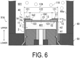
- FIG. 6 is a cross-sectional view illustrating a state near a cup body 1A before the igniter 40 is operated in an igniter assembly X1A according to a modified example of the first embodiment.
- the igniter assembly X1A according to the modified example will be described with focus on differences from the igniter assembly X1, and same and/or similar configurations will be denoted by the identical reference signs, and a detailed description will be omitted.
- the igniter assembly X1A is different from the igniter assembly X1 in that the cup body 1A is formed of two components. More specifically, the cup body 1A includes a cup main body 1b formed in a bottomed tubular shape, and an annular ring member 1c.
- the cup main body 1b includes the peripheral wall portion 11 and a lid wall portion main body 1b2 that closes one end portion (upper end portion) of the peripheral wall portion 11.
- a lid wall portion 12A is formed by installing the ring member 1c on this lid wall portion main body 1b2.
- the ring member 1c forms the outer peripheral region portion 121 together with the lid wall portion main body 1b2 by overlapping the lid wall portion main body 1b2.
- a region where the ring member 1c overlaps the lid wall portion main body 1b2 forms the outer peripheral region portion 121, and a region where the ring member 1c does not overlap the lid wall portion main body 1b2 forms the central region portion 122. Accordingly, the outer peripheral region portion 121 is formed thicker than the central region portion 122.
- a fitting portion 1c1 to be fitted to the lid wall portion main body 1b2 is formed in the ring member 1c. Accordingly, the ring member 1c is inhibited from falling off from the lid wall portion main body 1b2, and the cup main body 1b and the ring member 1c are integrally held.
- the lid wall portion 12A of the cup body 1A includes the annular outer peripheral region portion 121 disposed inside the peripheral wall portion 11 in the radial direction of the peripheral wall portion 11 and the central region portion 122 disposed inside the outer peripheral region portion 121 in the radial direction, and the outer peripheral region portion 121 is formed thicker than the central region portion 122.
- FIG. 7 is a cross-sectional view of an igniter assembly X2 according to the second embodiment.
- FIG. 7 illustrates a state before the igniter 40 is operated.
- the igniter assembly X2 according to the second embodiment is an igniter assembly of a gas generator for a seat belt retractor applied with the technology of the present disclosure.
- the application of the igniter assembly X2 according to the second embodiment is not limited to this, and may be applied to a gas generator for an airbag, for example.
- the igniter assembly X2 according to the second embodiment will be described with focus on differences from the igniter assembly X1 according to the first embodiment, and same and/or similar configurations will be denoted by the identical reference signs, and a detailed description will be omitted.
- the igniter assembly X2 is incorporated in a gas generator (not illustrated) for a seat belt retractor, and is configured to cause combustion of the first gas generating agent 110 filled in the emitting space 601 by operating the igniter 40 and emit the combustion gas that is a combustion product thereof for winding up loosening of a seat belt.
- the igniter assembly X2 includes the igniter 40, an attachment portion 80, the holding part 50, the tubular wall portion 60, and a lid member 90.
- the attachment portion 80 is a collar member formed of a metal material in a tubular shape, and is different from the attachment portion 304 according to the first embodiment in that the attachment portion 80 is separately from the housing.
- the pair of conductive pins 4 of the igniter 40 is inserted into the attachment portion 80.
- the igniter 40 is fixed to the attachment portion 80 by the holding part 50 provided between the igniter 40 and the attachment portion 80.
- the igniter assembly X2 is attached to the gas generator by fixing this attachment portion 80 to the housing of the gas generator.
- the lid member 90 is a member formed in a bottomed tubular shape, closes an opening 603 of the tubular wall portion 60 by being externally fitted to the upper end portion of the tubular wall portion 60, and defines the emitting space 601 together with the tubular wall portion 60.
- the communication hole 602 is not formed in the tubular wall portion 60 according to the second embodiment.
- the cup body 1 when the igniter 40 is operated, the cup body 1 is ruptured by the combustion of the ignition charge 3 in the accommodating space 401, and a high-temperature flame that is a combustion product of the ignition charge 3 is emitted to the emitting space 601. Accordingly, the first gas generating agent 110 filled in the emitting space 601 is ignited.
- the lid member 90 When the lid member 90 is ruptured by the combustion pressure of the first gas generating agent 110, the combustion gas of the first gas generating agent 110 is emitted from the opening 603 of the tubular wall portion 60.
- the lid wall portion 12 of the cup body 1 includes the annular outer peripheral region portion 121 disposed inside the peripheral wall portion 11 in the radial direction of the peripheral wall portion 11 and the central region portion 122 disposed inside the outer peripheral region portion 121 in the radial direction, and the outer peripheral region portion 121 is formed thicker than the central region portion 122.
- the igniter assembly X2 according to the second embodiment, it is possible to inhibit a large load from acting on the tubular wall portion 60 due to the lid wall portion 12 ruptured when the igniter 40 is operated, and it is possible to prevent problems such as a crack or damage from occurring in the tubular wall portion 60.
Landscapes
- Engineering & Computer Science (AREA)
- General Engineering & Computer Science (AREA)
- Physics & Mathematics (AREA)
- Fluid Mechanics (AREA)
- Mechanical Engineering (AREA)
- Air Bags (AREA)
Abstract
Description
- The present invention relates to an igniter assembly and a gas generator including the igniter assembly.
- An igniter is used as a starting device of a gas generator for an airbag or a gas generator for a seat belt retractor, and mainly an electric igniter is widely known which is operated by an ignition current. As a structure for attaching an igniter to a gas generator, an igniter assembly is known in which an igniter is attached via a resin to a tubular member provided in a housing.
- In this regard, in the gas generator presented in
Patent Document 1, an attachment portion having a tubular shape and attached with the igniter is formed at the central portion of the bottom plate of the housing, and the igniter is fixed to the attachment portion by a resin provided between the igniter and the attachment portion. This resin further forms a peripheral wall portion surrounding the igniter, and a space inside the peripheral wall portion is filled with a gas generating agent of which combustion is caused by operation of the igniter. A space into which a connector for supplying a current to the igniter is inserted is formed on the other end side of the attachment portion. -
- Patent Document 1:
US 7540241 - Patent Document 2:
US 5005486 - When the igniter is operated, a container made of metal and accommodating an ignition charge is ruptured to emit flame. In a structure where a peripheral wall portion made of resin surrounds the igniter, when the container ruptured by operation of the igniter comes into contact with the peripheral wall portion, the peripheral wall portion may be deformed by a load acting on the peripheral wall portion, and the peripheral wall portion may have a crack or damage. In such a case, depending on the state of the crack or damage, there is a concern that the holding of the igniter becomes insufficient or the sealability as the gas generator is impaired.
- The technology of the present disclosure has been made in view of the above problem, and an object is to provide a technology that can inhibit a large load from acting on a peripheral wall portion, made of resin, by a lid wall portion of a cup body ruptured when an igniter is operated in an igniter assembly having the structure where the peripheral wall portion surrounds the igniter.
- To solve the above problem, the technique of the present disclosure adopts the following configuration. That is, the technology of the present disclosure is an igniter assembly, including: an igniter including a container made of metal and an ignition charge, the igniter being configured to emit a combustion product of the ignition charge to an outside of the container when a lid wall portion is ruptured when the igniter is operated, the container including a peripheral wall portion having a tubular shape and the lid wall portion configured to close one end portion of the peripheral wall portion, the ignition charge being filled in an accommodating space defined by the peripheral wall portion and the lid wall portion; and a tubular wall portion made of resin and formed in a tubular shape in a manner that the peripheral wall portion is surrounded, the tubular wall portion inwardly forming an emitting space in which the combustion product of the ignition charge is emitted. The lid wall portion includes an annular outer peripheral region portion disposed inside the peripheral wall portion in a radial direction of the peripheral wall portion, and a central region portion positioned inside the outer peripheral region portion in a radial direction, and the outer peripheral region portion is formed thicker than the central region portion.
- When the igniter is operated, the lid wall portion is deformed and opens on the emitting space side from one end portion of the peripheral wall portion as a starting point by the combustion pressure of the ignition charge. At this time, in the igniter assembly of the present disclosure, since the outer peripheral region portion is formed thicker than the central region portion, the outer peripheral region portion has higher rigidity than a
central region portion 122 and is less likely to be deformed. As a result, since the outer peripheral region portion connected to the peripheral wall portion is less likely to be deformed, the lid wall portion is inhibited from largely opening. Thus, the ruptured lid wall portion is inhibited from coming into strong contact with the tubular wall portion. That is, the ruptured lid wall portion does not come into contact with the tubular wall portion, or even if coming into contact, a large load does not occur. As a result, according to the igniter assembly according to the present disclosure, it is possible to inhibit a large load from acting on the tubular wall portion due to the lid wall portion ruptured when the igniter is operated, the occurrence of a crack or damage in the tubular wall portion can be suppressed. - In the igniter assembly described above, the outer peripheral region portion and the central region portion may be connected in such a manner that an emitting surface facing the emitting space in the lid wall portion is recessed in the central region portion.
- In the igniter assembly described above, the central region may include a plurality of grooves extending radially from a central portion of the central region portion as a starting point.
- In the igniter assembly described above, a distance in the radial direction from the central portion of the central region portion to the outer peripheral region portion may be 1/2 or less of a distance in the radial direction from the central portion to the tubular wall portion.
- In the igniter assembly described above, the emitting space may be filled with a first gas generating agent to be ignited by a combustion product of the ignition charge.
- The technology of the present disclosure may be a gas generator including: the igniter assembly described above; a housing attached with the igniter assembly; a combustion chamber formed inside the housing and filled with a second gas generating agent of which combustion is caused by operation of the igniter; and a gas discharge port formed at the housing and allowing the combustion chamber and an external space of the housing to communicate with each other.
- The gas generating agent of the present disclosure includes a gas generating agent that generates a combustion gas for inflating an airbag, and a transfer charge for causing combustion of the gas generating agent.
- According to the present disclosure, it is possible to inhibit a large load from acting on a peripheral wall portion, made of resin, by a lid wall portion of a cup body ruptured when an igniter is operated in an igniter assembly having a structure in which the peripheral wall portion surrounds the igniter.
-
-
FIG. 1 is a cross-sectional view of a gas generator for an airbag including an igniter assembly according to a first embodiment. -
FIG. 2 is a cross-sectional view of the igniter assembly according to the first embodiment. -
FIG. 3 is a cross-sectional view illustrating a state near a cup body before an igniter is operated in the igniter assembly according to the first embodiment. -
FIG. 4 is a top view illustrating a state of a lid wall portion of the cup body before the igniter is operated in the igniter assembly according to the first embodiment. -
FIG. 5 is a cross-sectional view illustrating a state in which the igniter is operated and the lid wall portion of the cup body is ruptured in the igniter assembly according to the first embodiment. -
FIG. 6 is a cross-sectional view illustrating a state near the cup body before the igniter is operated in the igniter assembly according to a modified example of the first embodiment. -
FIG. 7 is a cross-sectional view of an igniter assembly according to a second embodiment. - Hereinafter, embodiments of the present disclosure will be described with reference to the drawings. Note that the respective configurations and the combinations thereof in the respective embodiments are examples, and the configurations can be added, omitted, substituted, and differently modified as appropriate within a scope not departing from the spirit of the present invention. The present disclosure is not limited to the embodiments, but only limited to the claims.
- Hereinafter, an aspect in which the technology of the present disclosure is applied to an igniter assembly of a gas generator for an airbag will be described as a first embodiment. However, the application of the igniter assembly according to the first embodiment is not limited to this, and may be applied to a gas generator for a seat belt retractor, for example.
FIG. 1 is a cross-sectional view of a gas generator for an airbag (hereinafter simply referred to as a gas generator) 100 including an igniter assembly X1 according to the first embodiment.FIG. 1 illustrates a state before the igniter indicated byreference sign 40 is operated. Thegas generator 100 is configured as a so-called single type gas generator including one igniter. As illustrated inFIG. 1 , thegas generator 100 includes ahousing 10, anigniter 40, aholding part 50, atubular wall portion 60, alid member 70, a spring member SP1, and a filter F1. Thegas generator 100 is configured to cause combustion of a firstgas generating agent 110 and a secondgas generating agent 120 filled in thehousing 10 by operating theigniter 40 disposed in thehousing 10, and to inflate an airbag (not illustrated) by emitting a combustion gas that is a combustion product to the outside of thehousing 10. Hereinafter, respective configurations of thegas generator 100 will be described. - As illustrated in
FIG. 1 , thehousing 10 is formed in a short tubular shape in which both ends in the axial direction are closed by joining, in a state where the opening ends face each other, an upper shell 20 and alower shell 30 made of metal and each formed in a bottomed tubular shape. However, the configuration of the upper shell 20 and thelower shell 30 are not limited to this, and a known configuration can be appropriately used. Here, a direction along the axial direction of thehousing 10 is defined as an up-down direction of thegas generator 100, the upper shell 20 side (that is, the upper side inFIG. 1 ) is defined as an upper side of thegas generator 100, and thelower shell 30 side (that is, the lower side inFIG. 1 ) is defined as a lower side of thegas generator 100. - The upper shell 20 includes an
upper tube portion 201 having a tubular shape, atop plate portion 202 that closes an upper end of theupper tube portion 201, and ajoint portion 203 extending radially outward from a lower end portion of theupper tube portion 201. Thelower shell 30 includes alower tube portion 301 having a tubular shape, abottom plate portion 302 that closes a lower end of thelower tube portion 301, and ajoint portion 303 extending radially outward from an upper end portion of thelower tube portion 301. Thejoint portion 203 of the upper shell 20 and thejoint portion 303 of thelower shell 30 are overlapped and joined by laser welding or the like to form thehousing 10. In theupper tube portion 201 of the upper shell 20, a plurality ofgas discharge ports 102 allowing the inside and the outside of thehousing 10 to communicate with each other are formed side by side along the circumferential direction. Before theigniter 40 is operated, thegas discharge port 102 is closed by a seal tape not illustrated. - Here, as illustrated in
FIG. 1 , thelower shell 30 of thehousing 10 is provided with anattachment portion 304 attached with theigniter 40. In the present embodiment, theattachment portion 304 is formed integrally with thebottom plate portion 302. That is, theattachment portion 304 made of metal is formed by a part of thehousing 10. As illustrated inFIG. 1 , theattachment portion 304 is formed in a substantially tubular shape with a part of thelower shell 30 protruding upward from thebottom plate portion 302. The upper end portion of theattachment portion 304 includes anattachment hole 304a through which a pair ofconductive pins 4 of theigniter 40 is inserted. The igniter assembly X1 according to the first embodiment includes theigniter 40, theattachment portion 304, the holdingpart 50, thetubular wall portion 60, and thelid member 70. -
FIG. 2 is a cross-sectional view of the igniter assembly X1 according to the first embodiment.FIG. 2 illustrates a state before theigniter 40 is operated. As illustrated inFIG. 2 , theigniter 40 includes acup body 1 which is made of metal and is an example of the "container" of the present disclosure, ametal header 2, anignition charge 3, and the pair of conductive pins 4 (41 and 42). Thecup body 1 is formed of a metal material in a bottomed tubular shape, and includes a tubularperipheral wall portion 11 and alid wall portion 12 that closes one end portion (upper end portion) of theperipheral wall portion 11. The metal material forming thecup body 1 is not particularly limited, and examples thereof include stainless steel, aluminum, and iron. Themetal header 2 is a closing member formed of a metal material in a circular columnar shape, is disposed inside thecup body 1, and closes an opening formed in the other end portion (lower end portion) of theperipheral wall portion 11. Themetal header 2 is welded to an inner wall of theperipheral wall portion 11 on the outer peripheral surface thereof. As illustrated inFIG. 2 , themetal header 2 is disposed inside thecup body 1 and closes the opening of theperipheral wall portion 11, whereby theperipheral wall portion 11 of thecup body 1 includes, in the axial direction thereof, a contact region A1 in contact with theperipheral wall portion 11 and a non-contact region A2 that is a region on thelid wall portion 12 side relative to the contact region A1 and is not in contact with themetal header 2. The non-contact region A2 of theperipheral wall portion 11, thelid wall portion 12, and themetal header 2 define anaccommodating space 401, which is a space filled with theignition charge 3. The pair ofconductive pins 4 extends downward from themetal header 2. A connector (not illustrated) for supplying electric power from an external power supply is connected to the pair ofconductive pins 4. - The
igniter 40 is operated by electric power supplied to each of theconductive pins 4 via the connector, and ignites theignition charge 3 filled in theaccommodating space 401. When thelid wall portion 12 of thecup body 1 is ruptured by the combustion pressure of theignition charge 3, the combustion product of theignition charge 3 is emitted to the outside of thecup body 1. - The holding
part 50 is formed of a resin material, and is provided between theigniter 40 and theattachment portion 304 to fix theigniter 40 to theattachment portion 304. At this time, as illustrated inFIG. 2 , the holdingpart 50 holds theigniter 40 in a state where thecup body 1 and themetal header 2 are positioned in thehousing 10, the pair ofconductive pins 4 is inserted into theattachment hole 304a, and the tips thereof are positioned outside thehousing 10. The holdingpart 50 covers the contact region A1 of theperipheral wall portion 11, themetal header 2, and theattachment portion 304 to fix theigniter 40 to theattachment portion 304, and closes theattachment hole 304a to maintain airtightness in thehousing 10. Apart of the holdingpart 50 forms, inside theattachment portion 304, aconnector insertion space 501 into which the connector for supplying electric power to theconductive pins 4 can be inserted. The holdingpart 50 holds theigniter 40 in such a manner that the non-contact region A2 of theperipheral wall portion 11 and thelid wall portion 12 are exposed in an emittingspace 601 described below, and the lower end of the pair ofconductive pins 4 is exposed in theconnector insertion space 501. The insulating property between the pair ofconductive pins 4 is maintained by covering a part of the pair ofconductive pins 4 with the holdingpart 50. - As illustrated in
FIG. 2 , thetubular wall portion 60 is formed in a tubular shape by a resin material, surrounds the peripheral wall portion 11 (more specifically, the non-contact region A2 of the peripheral wall portion 11) of thecup body 1, and extends upward from the holdingpart 50. Inside thetubular wall portion 60, the emittingspace 601, which is a space where a combustion product of theignition charge 3 is emitted, is formed. The emittingspace 601 is filled with the first gas generating agent 110of which combustion is caused by operation of theigniter 40. The firstgas generating agent 110 is ignited by the combustion product of theignition charge 3 emitted by operation of theigniter 40 and generates a combustion gas. The holdingpart 50 and thetubular wall portion 60 are integrally formed as one member and are continuous with each other. In thetubular wall portion 60, a plurality ofcommunication holes 602 allowing the inside and the outside of the emittingspace 601 to communicate with each other are formed side by side along the circumferential direction. - The holding
part 50 and thetubular wall portion 60 are integrally formed by injection-molding a resin material in a manufacturing process of the igniter assembly X1. As the resin material forming the holdingpart 50 and thetubular wall portion 60, a resin material having excellent heat resistance, durability, corrosion resistance, and the like after curing can be suitably used. Examples of such resin material include: thermoplastic resins such as polybutylene terephthalate resin, polyethylene terephthalate resin, polyamide resin, polypropylene sulfide resin, and polypropylene oxide resin; and thermosetting resins such as epoxy resin. - As illustrated in
FIG. 1 , thelid member 70 is a member that defines the emittingspace 601 together with thetubular wall portion 60 by being fitted into thetubular wall portion 60 from an opening formed at the upper end portion of thetubular wall portion 60. As illustrated inFIG. 1 , thelid member 70 closes thecommunication hole 602 by covering thecommunication hole 602 from the inside of thetubular wall portion 60 before theigniter 40 is operated. - As illustrated in
FIG. 1 , the spring member SP1 is an elastic member provided between thelid member 70 and thetop plate portion 202 of the upper shell 20. The spring member SP1 presses thelid member 70 downward (that is, the emittingspace 601 side) by its biasing force, thereby inhibiting thelid member 70 from coming out of thetubular wall portion 60 and inhibiting the firstgas generating agent 110 filled in the emittingspace 601 from rattling. - As illustrated in
FIG. 1 , the filter F1 is formed in a tubular shape, and is arranged between the igniter assembly X1 and thegas discharge port 102 in a state where the upper end portion is supported by thetop plate portion 202 of the upper shell 20 and the lower end portion is supported by thebottom plate portion 302 of thelower shell 30. Accordingly, acombustion chamber 101 is formed between the igniter assembly X1 and the filter F1. Thecombustion chamber 101 is filled with the secondgas generating agent 120 of which combustion is caused by operation of theigniter 40. The secondgas generating agent 120 is ignited by the combustion gas of the firstgas generating agent 110 of which combustion is caused by operation of theigniter 40 and generates a combustion gas. The filter F1 is configured to allow the combustion gas to pass therethrough, and the combustion gas in thecombustion chamber 101 is cooled by passing through the filter F1. At this time, the filter F1 filters the combustion gas by filtering a combustion residue of the combustion gas. - The first
gas generating agent 110 uses a gas generating agent having a relatively low combustion temperature. The combustion temperature of the firstgas generating agent 110 is desirably within a range from 1000°C to 1700°C, and for example, a single-hole circular columnar-type gas generating agent may be used, which includes guanidine nitrate (41 wt.%), basic copper nitrate (49 wt.%), and a binder and an additive. Furthermore, the same and/or similar type of gas generating agent as the firstgas generating agent 110 can be used for the secondgas generating agent 120. However, the firstgas generating agent 110 and the secondgas generating agent 120 are not limited to those described above. The firstgas generating agent 110 and the secondgas generating agent 120 may be gas generating agents of an identical type, an identical shape, and an identical dimension, or may be gas generating agents of different types, different shapes, or different dimensions. - Next, operations of the
gas generator 100 will be described. In a state where thegas generator 100 is assembled to an automobile, the connector inserted into theconnector insertion space 501 is connected to theigniter 40, and power can be supplied to theigniter 40. In this state, when a sensor (not illustrated) mounted on the automobile detects an impact, electric power from an external power supply is supplied to the pair ofconductive pins 4 via the connector, whereby theigniter 40 is operated and causes combustion of theignition charge 3 in theaccommodating space 401. - As the pressure in the
accommodating space 401 rises with the combustion of theignition charge 3, thecup body 1 ruptures, and a high-temperature flame that is a combustion product of theignition charge 3 is emitted to the emittingspace 601. Accordingly, the firstgas generating agent 110 in the emittingspace 601 is ignited. Due to the pressure (hereinafter, also called combustion pressure) of the combustion gas of the firstgas generating agent 110, thelid member 70 slides upward (that is, the opening end portion side of the tubular wall portion 60) against the biasing force of the spring member SP1. Accordingly, the closed state of thecommunication hole 602 by thelid member 70 is released, and the combustion gas of the firstgas generating agent 110 is emitted from thecommunication hole 602 to thecombustion chamber 101. - The second
gas generating agent 120 is ignited by the combustion gas of the firstgas generating agent 110 emitted from thecommunication hole 602 to thecombustion chamber 101, whereby the combustion gas of the secondgas generating agent 120 is generated in thecombustion chamber 101. The combustion gas in thecombustion chamber 101 is cooled and filtered by the filter F1, then breaks a seal tape closing thegas discharge port 102, and is emitted from thegas discharge port 102 to the outside of thehousing 10. Accordingly, the airbag is inflated, a cushion is formed between an occupant and a hard structure, and thus the occupant is protected from the impact. - When the
igniter 40 is operated, the pressure in theaccommodating space 401 rises due to the combustion of theignition charge 3 filled in theaccommodating space 401, whereby thelid wall portion 12 of thecup body 1 is ruptured. Accordingly, a flame that is a combustion product of theignition charge 3 is emitted into the emittingspace 601, and the firstgas generating agent 110 in the emittingspace 601 is ignited. At this time, thelid wall portion 12 of thecup body 1 is ruptured from the central portion, as a starting point, in the radial direction of theperipheral wall portion 11, and thelid wall portion 12 is deformed and thus opens outward in the radial direction from the upper end portion, as the starting point, of theperipheral wall portion 11. In the following description, the "radial direction" refers to the radial direction of theperipheral wall portion 11 unless otherwise specified. Here, if thelid wall portion 12 ruptured by thelid wall portion 12 largely opening comes into strong contact with thetubular wall portion 60, and a large load acts on thetubular wall portion 60, thetubular wall portion 60 is deformed and may have a crack or damage. In such a case, there is a concern that the crack or damage propagates to the holdingpart 50, holding of theigniter 40 becomes insufficient, or the sealability of thegas generator 100 is impaired. - On the other hand, in the igniter assembly X1 according to the present embodiment, the
lid wall portion 12 of thecup body 1 is configured in such a manner that thelid wall portion 12 can be inhibited from largely opening when theigniter 40 is operated and a large load can be inhibited from acting on thetubular wall portion 60. Hereinafter, thelid wall portion 12 will be described in detail. -
FIG. 3 is a cross-sectional view illustrating a state near thecup body 1 before theigniter 40 is operated in the igniter assembly X1 according to the first embodiment.FIG. 4 is a top view illustrating a state of thelid wall portion 12 of thecup body 1 before theigniter 40 is operated in the igniter assembly X1 according to the first embodiment. As illustrated inFIGS. 3 and4 , thelid wall portion 12 of thecup body 1 according to the present embodiment includes an annular outerperipheral region portion 121 connected to the upper end portion (one end portion) of theperipheral wall portion 11, and thecentral region portion 122 positioned radially inward of the outerperipheral region portion 121. - As illustrated in
FIG. 3 , the outerperipheral region portion 121 extends radially inward from the upper end portion of theperipheral wall portion 11, and is formed in an annular shape about a central axis CA1 of theperipheral wall portion 11. Thecentral region portion 122 is a portion, surrounded by the outerperipheral region portion 121, of thelid wall portion 12, and is connected to an inner peripheral edge of the outerperipheral region portion 121. Thecentral region portion 122 is formed at a position radially inward of the outerperipheral region portion 121, and the central portion C1 in the radial direction of thecentral region portion 122 is positioned on the central axis CA1 of theperipheral wall portion 11. As illustrated inFIG. 3 , when the thickness of the outer peripheral region portion 121 (thickness in the axial direction of the peripheral wall portion 11) is T1 and the thickness of thecentral region portion 122 is T2, T1 > T2 holds. That is, the outerperipheral region portion 121 is formed thicker than thecentral region portion 122. - Here, a surface (that is, the upper surface of the lid wall portion 12) of the
lid wall portion 12 facing the emittingspace 601 is an emitting surface S1, and the opposite surface (that is, the lower surface of the lid wall portion 12) defining theaccommodating space 401 is an accommodating surface S2. At this time, as illustrated inFIG. 3 , the outerperipheral region portion 121 and thecentral region portion 122 are connected in such a manner that the emitting surface S1 is recessed on theaccommodating space 401 side in thecentral region portion 122. Accordingly, the connection portion between the outerperipheral region portion 121 and thecentral region portion 122 forms astep portion 123 on the emittingspace 601 side. - As illustrated in
FIG. 4 , a plurality ofgrooves 13 extending radially from the central portion C1, as a starting point, of thecentral region portion 122 are formed in thecentral region portion 122. The plurality ofgrooves 13 are formed on the emitting surface S1 side, and extend in the radial direction between the central portion C1 and the outerperipheral region portion 121. As illustrated inFIG. 4 , in the present embodiment, eightgrooves 13 are formed at equal angular intervals. However, the technique according to the present disclosure is not limited to such a configuration. - As illustrated in
FIG. 3 , when a distance in the radial direction from the central portion C1 of thecentral region portion 122 to the outerperipheral region portion 121 is d1, and a distance in the radial direction from the central portion C1 to the tubular wall portion 60 (more specifically, an innerperipheral surface 60a of the tubular wall portion 60) is d2, d1 ≤ 1/2 × d2 holds. That is, d1 is 1/2 or less of d2. -
FIG. 5 is a cross-sectional view illustrating a state in which theigniter 40 is operated and thelid wall portion 12 of thecup body 1 is ruptured in the igniter assembly X1 according to the first embodiment. As described above, the igniter assembly X1 according to the present embodiment includes theigniter 40 that emits the combustion product of theignition charge 3 to the outside of thecup body 1 when thelid wall portion 12 of thecup body 1 made of metal is ruptured when theigniter 40 is operated, and thetubular wall portion 60 made of resin and formed in a tubular shape in a manner that theperipheral wall portion 11 of thecup body 1 is surrounded, thetubular wall portion 60 inwardly forming the emittingspace 601 in which the combustion product of theignition charge 3 is emitted. Thelid wall portion 12 includes the annular outerperipheral region portion 121 disposed inside theperipheral wall portion 11 in the radial direction of theperipheral wall portion 11 and thecentral region portion 122 disposed inside the outerperipheral region portion 121 in the radial direction, and the outerperipheral region portion 121 is formed thicker than thecentral region portion 122. - Since the
central region portion 122 is thinner than the outerperipheral region portion 121, when theigniter 40 is operated and thelid wall portion 12 of thecup body 1 is ruptured, the rupture starts from thecentral region portion 122 as illustrated inFIG. 5 . At this time, thelid wall portion 12 is deformed and thus opens on the emittingspace 601 side from the upper end portion, as a starting point, of theperipheral wall portion 11 by the combustion pressure of theignition charge 3. Here, in the igniter assembly X1, since the outerperipheral region portion 121 is formed thicker than thecentral region portion 122, the outerperipheral region portion 121 is higher in rigidity and is less likely to be deformed than thecentral region portion 122. As a result, since the outerperipheral region portion 121 connected to theperipheral wall portion 11 is less likely to be deformed, thelid wall portion 12 is inhibited from largely opening. Thus, the rupturedlid wall portion 12 is inhibited from coming into strong contact with thetubular wall portion 60. That is, the rupturedlid wall portion 12 does not come into contact with thetubular wall portion 60, or even if the rupturedlid wall portion 12 comes into contact with the tubular wall portion 6, a large load does not occur. - Thus, according to the igniter assembly X1 according to the present embodiment, it is possible to inhibit a large load from acting on the
tubular wall portion 60 due to thelid wall portion 12 ruptured when theigniter 40 is operated, and the occurrence of a crack or damage in thetubular wall portion 60 can be suppressed. - As illustrated in
FIG. 5 , when thelid wall portion 12 is ruptured by operation of theigniter 40, thecentral region portion 122 is deformed and thus opens on the emittingspace 601 side from the connection portion with the outerperipheral region portion 121 as the starting point. Here, in the igniter assembly X1, the outerperipheral region portion 121 and thecentral region portion 122 are connected in such a manner that the emitting surface S1 of thelid wall portion 12 is recessed in thecentral region portion 122, whereby the connection portion between the outerperipheral region portion 121 and thecentral region portion 122 forms thestep portion 123 on the emittingspace 601 side. Therefore, as illustrated inFIG. 5 , thecentral region portion 122 is inhibited from further opening by thestep portion 123 abutting on thecentral region portion 122. As a result, the igniter assembly X1 can inhibit thecentral region portion 122 ruptured when theigniter 40 is operated from largely opening and coming into strong contact with thetubular wall portion 60. The technology of the present disclosure is not limited to this, and the outer peripheral region portion and the central region portion may be connected in such a manner that the central region portion is recessed on the accommodating surface facing the accommodating space. - Furthermore, in the igniter assembly X1 according to the present embodiment, the plurality of
grooves 13 radially extending from the central portion C1 of thecentral region portion 122 as the starting point is formed in thecentral region portion 122 of thelid wall portion 12. The portion of thecentral region portion 122 where thegroove 13 is formed is more fragile than other portions. In the igniter assembly X1, since the plurality ofgrooves 13 are radially formed from the central portion C1 as the starting point, thelid wall portion 12 can be easily ruptured. Furthermore, in the igniter assembly X1, thegroove 13 is formed only in thecentral region portion 122 of the outerperipheral region portions lid wall portion 12 can be easily ruptured while suppressing deformation of the outerperipheral region portion 121. In the technology of the present disclosure, the groove in the central region portion is not necessarily formed. - Furthermore, in the igniter assembly X1 according to the present embodiment, the distance d1 in the radial direction from the central portion C1 of the
central region portion 122 of thelid wall portion 12 to the outerperipheral region portion 121 is 1/2 or less of the distance in the radial direction from the central portion C1 to thetubular wall portion 60. In this manner, even when thecentral region portion 122 is deformed and thus folded back from the connection portion with the outerperipheral region portion 121 when theigniter 40 is operated, and even if thecentral region portion 122 falls on thetubular wall portion 60 side, thecentral region portion 122 does not reach thetubular wall portion 60. As a result, according to the igniter assembly X1, it is possible to inhibit thecentral region portion 122 ruptured when theigniter 40 is operated from coming into contact with thetubular wall portion 60. However, the technique according to the present disclosure is not limited to such a configuration. -
FIG. 6 is a cross-sectional view illustrating a state near acup body 1A before theigniter 40 is operated in an igniter assembly X1A according to a modified example of the first embodiment. Hereinafter, the igniter assembly X1A according to the modified example will be described with focus on differences from the igniter assembly X1, and same and/or similar configurations will be denoted by the identical reference signs, and a detailed description will be omitted. - As illustrated in
FIG. 6 , the igniter assembly X1A according to the modified example is different from the igniter assembly X1 in that thecup body 1A is formed of two components. More specifically, thecup body 1A includes a cupmain body 1b formed in a bottomed tubular shape, and an annular ring member 1c. The cupmain body 1b includes theperipheral wall portion 11 and a lid wall portion main body 1b2 that closes one end portion (upper end portion) of theperipheral wall portion 11. Alid wall portion 12A is formed by installing the ring member 1c on this lid wall portion main body 1b2. The ring member 1c forms the outerperipheral region portion 121 together with the lid wall portion main body 1b2 by overlapping the lid wall portion main body 1b2. In thelid wall portion 12A, a region where the ring member 1c overlaps the lid wall portion main body 1b2 forms the outerperipheral region portion 121, and a region where the ring member 1c does not overlap the lid wall portion main body 1b2 forms thecentral region portion 122. Accordingly, the outerperipheral region portion 121 is formed thicker than thecentral region portion 122. As illustrated inFIG. 6 , a fitting portion 1c1 to be fitted to the lid wall portion main body 1b2 is formed in the ring member 1c. Accordingly, the ring member 1c is inhibited from falling off from the lid wall portion main body 1b2, and the cupmain body 1b and the ring member 1c are integrally held. - In the igniter assembly X1A according to the modified example, the
lid wall portion 12A of thecup body 1A includes the annular outerperipheral region portion 121 disposed inside theperipheral wall portion 11 in the radial direction of theperipheral wall portion 11 and thecentral region portion 122 disposed inside the outerperipheral region portion 121 in the radial direction, and the outerperipheral region portion 121 is formed thicker than thecentral region portion 122. As a result, similarly to the igniter assembly X1, it is possible to inhibit a large load from acting on thetubular wall portion 60 due to thelid wall portion 12A ruptured when theigniter 40 is operated, and the occurrence of a crack or damage in thetubular wall portion 60 can be suppressed. -
FIG. 7 is a cross-sectional view of an igniter assembly X2 according to the second embodiment.FIG. 7 illustrates a state before theigniter 40 is operated. The igniter assembly X2 according to the second embodiment is an igniter assembly of a gas generator for a seat belt retractor applied with the technology of the present disclosure. However, the application of the igniter assembly X2 according to the second embodiment is not limited to this, and may be applied to a gas generator for an airbag, for example. Hereinafter, the igniter assembly X2 according to the second embodiment will be described with focus on differences from the igniter assembly X1 according to the first embodiment, and same and/or similar configurations will be denoted by the identical reference signs, and a detailed description will be omitted. - The igniter assembly X2 according to the second embodiment is incorporated in a gas generator (not illustrated) for a seat belt retractor, and is configured to cause combustion of the first
gas generating agent 110 filled in the emittingspace 601 by operating theigniter 40 and emit the combustion gas that is a combustion product thereof for winding up loosening of a seat belt. - As illustrated in
FIG. 7 , the igniter assembly X2 according to the second embodiment includes theigniter 40, anattachment portion 80, the holdingpart 50, thetubular wall portion 60, and alid member 90. Theattachment portion 80 is a collar member formed of a metal material in a tubular shape, and is different from theattachment portion 304 according to the first embodiment in that theattachment portion 80 is separately from the housing. The pair ofconductive pins 4 of theigniter 40 is inserted into theattachment portion 80. Theigniter 40 is fixed to theattachment portion 80 by the holdingpart 50 provided between theigniter 40 and theattachment portion 80. The igniter assembly X2 is attached to the gas generator by fixing thisattachment portion 80 to the housing of the gas generator. Thelid member 90 is a member formed in a bottomed tubular shape, closes anopening 603 of thetubular wall portion 60 by being externally fitted to the upper end portion of thetubular wall portion 60, and defines the emittingspace 601 together with thetubular wall portion 60. Thecommunication hole 602 is not formed in thetubular wall portion 60 according to the second embodiment. - In the second embodiment, when the
igniter 40 is operated, thecup body 1 is ruptured by the combustion of theignition charge 3 in theaccommodating space 401, and a high-temperature flame that is a combustion product of theignition charge 3 is emitted to the emittingspace 601. Accordingly, the firstgas generating agent 110 filled in the emittingspace 601 is ignited. When thelid member 90 is ruptured by the combustion pressure of the firstgas generating agent 110, the combustion gas of the firstgas generating agent 110 is emitted from theopening 603 of thetubular wall portion 60. - As described above, also in the igniter assembly X2 according to the second embodiment, the
lid wall portion 12 of thecup body 1 includes the annular outerperipheral region portion 121 disposed inside theperipheral wall portion 11 in the radial direction of theperipheral wall portion 11 and thecentral region portion 122 disposed inside the outerperipheral region portion 121 in the radial direction, and the outerperipheral region portion 121 is formed thicker than thecentral region portion 122. As a result, same and/or similar effects to those of the igniter assembly X1 according to the first embodiment can be achieved. That is, according to the igniter assembly X2 according to the second embodiment, it is possible to inhibit a large load from acting on thetubular wall portion 60 due to thelid wall portion 12 ruptured when theigniter 40 is operated, and it is possible to prevent problems such as a crack or damage from occurring in thetubular wall portion 60. - While embodiments of the ignition device and the ignition device assembly according to the present disclosure have been described above, each aspect disclosed in the present description can be combined with any other features disclosed in the present description. In the above embodiments, an example in which the igniter assembly of the present disclosure is applied to a single type gas generator including only one igniter has been described, but the igniter assembly of the present disclosure may also be applied to a gas generator including a plurality of igniters. In the above embodiments, an example in which the igniter assembly is applied to a gas generator for an airbag or a seat belt retractor has been described, but the igniter assembly may be applied to another gas generator. A housing other than the housing of the gas generator may be used as an attachment target object of the igniter assembly.
-
- 1 ••• Cup body (example of container)
- 11 ••• Peripheral wall portion
- 12 ••• Lid wall portion
- 121 ••• Outer peripheral region portion
- 122 ••• Central region portion
- 13 ••• Groove
- 3 ••• Ignition charge
- 10 ••• Housing
- 40 ••• Igniter
- 401 ••• Accommodating space
- 50 ••• Holding part
- 60 ••• Tubular wall portion
- 601 ••• Emitting space
- 100 ••• Gas generator
- 101 ••• Combustion chamber
- 102 ••• Gas discharge port
- 110 ••• First gas generating agent
- 120 ••• When second gas is generated
- X1 ••• Igniter assembly
- S1 ••• Emitting surface
Claims (6)
- An igniter assembly, comprising:an igniter including a container made of metal and an ignition charge, the igniter being configured to emit a combustion product of the ignition charge to an outside of the container when a lid wall portion is ruptured when the igniter is operated, the container including a peripheral wall portion having a tubular shape and the lid wall portion configured to close one end portion of the peripheral wall portion, the ignition charge being filled in an accommodating space defined by the peripheral wall portion and the lid wall portion; anda tubular wall portion made of resin and formed in a tubular shape in a manner that the peripheral wall portion is surrounded, the tubular wall portion inwardly forming an emitting space in which the combustion product of the ignition charge is emitted, whereinthe lid wall portion includes an annular outer peripheral region portion disposed inside the peripheral wall portion in a radial direction of the peripheral wall portion, and a central region portion positioned inside the outer peripheral region portion in a radial direction, andthe outer peripheral region portion is formed thicker than the central region portion.
- The igniter assembly according to claim 1, wherein
the outer peripheral region portion and the central region portion are connected in a manner that an emitting surface facing the emitting space at the lid wall portion is recessed at the central region portion. - The igniter assembly according to claim 1 or 2, wherein
the central region portion includes a plurality of grooves radially extending from a central portion, as a starting point, of the central region portion. - The igniter assembly according to any one of claims 1 to 3, wherein
a distance in the radial direction from the central portion of the central region portion to the outer peripheral region portion is 1/2 or less of a distance in the radial direction from the central portion to the tubular wall portion. - The igniter assembly according to any one of claims 1 to 4, wherein the emitting space is filled with a first gas generating agent that is ignited by a combustion product of the ignition charge.
- A gas generator, comprising:the igniter assembly according to any one of claims 1 to 5;a housing attached with the igniter assembly;a combustion chamber formed inside the housing and filled with a second gas generating agent of which combustion is caused by operation of the igniter; anda gas discharge port formed at the housing and causing the combustion chamber and an external space of the housing to communicate with each other.
Applications Claiming Priority (2)
| Application Number | Priority Date | Filing Date | Title |
|---|---|---|---|
| JP2021016735A JP7553375B2 (en) | 2021-02-04 | 2021-02-04 | Igniter assembly and gas generator |
| PCT/JP2022/003603 WO2022168795A1 (en) | 2021-02-04 | 2022-01-31 | Igniter assembly and gas generator |
Publications (2)
| Publication Number | Publication Date |
|---|---|
| EP4289680A1 true EP4289680A1 (en) | 2023-12-13 |
| EP4289680A4 EP4289680A4 (en) | 2024-12-25 |
Family
ID=82741437
Family Applications (1)
| Application Number | Title | Priority Date | Filing Date |
|---|---|---|---|
| EP22749667.6A Pending EP4289680A4 (en) | 2021-02-04 | 2022-01-31 | IGNITER ARRANGEMENT AND GAS GENERATOR |
Country Status (5)
| Country | Link |
|---|---|
| US (1) | US12534041B2 (en) |
| EP (1) | EP4289680A4 (en) |
| JP (1) | JP7553375B2 (en) |
| CN (1) | CN116917167B (en) |
| WO (1) | WO2022168795A1 (en) |
Families Citing this family (2)
| Publication number | Priority date | Publication date | Assignee | Title |
|---|---|---|---|---|
| JP7587443B2 (en) * | 2021-03-02 | 2024-11-20 | 日本化薬株式会社 | Igniters and gas generators |
| JP7808458B2 (en) * | 2021-11-12 | 2026-01-29 | 株式会社ダイセル | Gas generator filter unit, gas generator, and method for manufacturing gas generator |
Family Cites Families (21)
| Publication number | Priority date | Publication date | Assignee | Title |
|---|---|---|---|---|
| US3211097A (en) * | 1964-06-29 | 1965-10-12 | Kenneth R Foote | Pyrogen squib |
| US5005486A (en) | 1989-02-03 | 1991-04-09 | Trw Vehicle Safety Systems Inc. | Igniter for airbag propellant grains |
| US5564743A (en) * | 1995-03-22 | 1996-10-15 | Morton International, Inc. | Multiple stage air bag inflator system |
| WO1997028025A1 (en) * | 1996-01-31 | 1997-08-07 | Matsushita Electric Industrial Co., Ltd. | Gas generating device for air bag and air bag inflation method |
| JPH1095303A (en) * | 1996-07-31 | 1998-04-14 | Daicel Chem Ind Ltd | Air bag gas generator and air bag device |
| DE10216702A1 (en) | 2001-04-19 | 2002-11-07 | Dynamit Nobel Gmbh | Electrical igniter, e.g. for airbag, has strengthening element for preventing fragmentation on bounding peripheral surface at least near end surface with preferred breakage point |
| CZ20033416A3 (en) | 2001-05-15 | 2004-04-14 | Nippon Kayaku Kabushiki-Kaisha | Gas generator |
| US6644206B2 (en) * | 2001-12-21 | 2003-11-11 | Trw Inc. | Electrically actuatable initiator with output charge |
| JP2003226221A (en) * | 2002-02-07 | 2003-08-12 | Takata Corp | Inflator and its closure fixing structure |
| JP4633522B2 (en) | 2005-04-05 | 2011-02-16 | ダイセル化学工業株式会社 | Igniter assembly |
| DE202005007611U1 (en) | 2005-05-13 | 2005-09-22 | Trw Airbag Systems Gmbh | inflator |
| JP4907931B2 (en) * | 2005-09-15 | 2012-04-04 | 日本化薬株式会社 | Gas generator |
| KR101782076B1 (en) | 2008-09-30 | 2017-09-26 | 티알더블유 에어백 시스템즈 게엠베하 | Gas generator, method for the production thereof and module having a gas generator |
| MX2013000536A (en) * | 2010-07-15 | 2013-07-29 | Nippon Kayaku Kk | Igniting powder composition for igniters. |
| JP5638963B2 (en) * | 2011-01-07 | 2014-12-10 | 日本化薬株式会社 | Gas generator |
| JP5327389B2 (en) * | 2011-05-12 | 2013-10-30 | トヨタ自動車株式会社 | Inflator and airbag device |
| JP6312545B2 (en) * | 2014-07-24 | 2018-04-18 | 日本化薬株式会社 | Gas generator |
| JP6655897B2 (en) * | 2015-07-03 | 2020-03-04 | 株式会社ダイセル | Ignition means and gas generator using it |
| JP6701040B2 (en) * | 2016-09-14 | 2020-05-27 | 日本化薬株式会社 | Gas generator filter and gas generator |
| JP6835315B2 (en) * | 2017-05-18 | 2021-02-24 | 株式会社ダイセル | Gas generator and storage container |
| JP7257190B2 (en) | 2019-03-06 | 2023-04-13 | 株式会社ダイセル | IGNITOR ASSEMBLY, HOLDING PART FORMING METHOD, AND GAS GENERATOR |
-
2021
- 2021-02-04 JP JP2021016735A patent/JP7553375B2/en active Active
-
2022
- 2022-01-31 CN CN202280013144.3A patent/CN116917167B/en active Active
- 2022-01-31 US US18/275,657 patent/US12534041B2/en active Active
- 2022-01-31 WO PCT/JP2022/003603 patent/WO2022168795A1/en not_active Ceased
- 2022-01-31 EP EP22749667.6A patent/EP4289680A4/en active Pending
Also Published As
| Publication number | Publication date |
|---|---|
| US20240294138A1 (en) | 2024-09-05 |
| CN116917167A (en) | 2023-10-20 |
| CN116917167B (en) | 2026-05-12 |
| EP4289680A4 (en) | 2024-12-25 |
| JP2022119533A (en) | 2022-08-17 |
| JP7553375B2 (en) | 2024-09-18 |
| WO2022168795A1 (en) | 2022-08-11 |
| US12534041B2 (en) | 2026-01-27 |
Similar Documents
| Publication | Publication Date | Title |
|---|---|---|
| US8708368B2 (en) | Gas generator | |
| EP1491848B1 (en) | Initiator | |
| KR101774077B1 (en) | Gas generator | |
| KR101998446B1 (en) | Gas generator | |
| US12534041B2 (en) | Igniter assembly and gas generator | |
| EP1227016A1 (en) | Gas generator | |
| JP2016022930A (en) | Gas generator | |
| US12018921B2 (en) | Gas generator | |
| US11958432B2 (en) | Igniter holding structure | |
| US12510335B2 (en) | Gas generator | |
| US20240190377A1 (en) | Airbag device and gas generator | |
| EP1491849B1 (en) | Initiator | |
| US10981535B2 (en) | Gas generator | |
| US20250206254A1 (en) | Igniter Assembly and Gas Generation Device | |
| JP4912942B2 (en) | Gas generator | |
| CN116056783B (en) | Ignition device assembly and ignition device | |
| US20170341620A1 (en) | Support structure of closing member for gas generator and gas generator using same | |
| CN113043989A (en) | Gas generator | |
| US20250180338A1 (en) | Ignition device | |
| JP2008018856A (en) | Gas generator for vehicle restraint system | |
| US20250091544A1 (en) | Gas generator | |
| US11993222B2 (en) | Igniter assembly and gas generator provided with same | |
| JP2000329500A (en) | Squib | |
| JP7346327B2 (en) | Gas generator installation structure | |
| JP5305991B2 (en) | Small gas generator |
Legal Events
| Date | Code | Title | Description |
|---|---|---|---|
| STAA | Information on the status of an ep patent application or granted ep patent |
Free format text: STATUS: THE INTERNATIONAL PUBLICATION HAS BEEN MADE |
|
| PUAI | Public reference made under article 153(3) epc to a published international application that has entered the european phase |
Free format text: ORIGINAL CODE: 0009012 |
|
| STAA | Information on the status of an ep patent application or granted ep patent |
Free format text: STATUS: REQUEST FOR EXAMINATION WAS MADE |
|
| 17P | Request for examination filed |
Effective date: 20230807 |
|
| AK | Designated contracting states |
Kind code of ref document: A1 Designated state(s): AL AT BE BG CH CY CZ DE DK EE ES FI FR GB GR HR HU IE IS IT LI LT LU LV MC MK MT NL NO PL PT RO RS SE SI SK SM TR |
|
| DAV | Request for validation of the european patent (deleted) | ||
| DAX | Request for extension of the european patent (deleted) | ||
| A4 | Supplementary search report drawn up and despatched |
Effective date: 20241126 |
|
| RIC1 | Information provided on ipc code assigned before grant |
Ipc: B60R 21/26 20110101ALI20241121BHEP Ipc: F42B 3/103 20060101ALI20241121BHEP Ipc: F42B 3/12 20060101ALI20241121BHEP Ipc: F42B 3/04 20060101ALI20241121BHEP Ipc: B60R 21/264 20060101AFI20241121BHEP |