EP4289638A1 - Heat shield panel retainer - Google Patents
Heat shield panel retainer Download PDFInfo
- Publication number
- EP4289638A1 EP4289638A1 EP22461570.8A EP22461570A EP4289638A1 EP 4289638 A1 EP4289638 A1 EP 4289638A1 EP 22461570 A EP22461570 A EP 22461570A EP 4289638 A1 EP4289638 A1 EP 4289638A1
- Authority
- EP
- European Patent Office
- Prior art keywords
- retainer
- heat shield
- panel
- panels
- wheel
- Prior art date
- Legal status (The legal status is an assumption and is not a legal conclusion. Google has not performed a legal analysis and makes no representation as to the accuracy of the status listed.)
- Pending
Links
Images
Classifications
-
- B—PERFORMING OPERATIONS; TRANSPORTING
- B60—VEHICLES IN GENERAL
- B60C—VEHICLE TYRES; TYRE INFLATION; TYRE CHANGING; CONNECTING VALVES TO INFLATABLE ELASTIC BODIES IN GENERAL; DEVICES OR ARRANGEMENTS RELATED TO TYRES
- B60C23/00—Devices for measuring, signalling, controlling, or distributing tyre pressure or temperature, specially adapted for mounting on vehicles; Arrangement of tyre inflating devices on vehicles, e.g. of pumps or of tanks; Tyre cooling arrangements
- B60C23/18—Tyre cooling arrangements, e.g. heat shields
-
- F—MECHANICAL ENGINEERING; LIGHTING; HEATING; WEAPONS; BLASTING
- F16—ENGINEERING ELEMENTS AND UNITS; GENERAL MEASURES FOR PRODUCING AND MAINTAINING EFFECTIVE FUNCTIONING OF MACHINES OR INSTALLATIONS; THERMAL INSULATION IN GENERAL
- F16D—COUPLINGS FOR TRANSMITTING ROTATION; CLUTCHES; BRAKES
- F16D55/00—Brakes with substantially-radial braking surfaces pressed together in axial direction, e.g. disc brakes
- F16D55/24—Brakes with substantially-radial braking surfaces pressed together in axial direction, e.g. disc brakes with a plurality of axially-movable discs, lamellae, or pads, pressed from one side towards an axially-located member
- F16D55/26—Brakes with substantially-radial braking surfaces pressed together in axial direction, e.g. disc brakes with a plurality of axially-movable discs, lamellae, or pads, pressed from one side towards an axially-located member without self-tightening action
- F16D55/36—Brakes with a plurality of rotating discs all lying side by side
-
- F—MECHANICAL ENGINEERING; LIGHTING; HEATING; WEAPONS; BLASTING
- F16—ENGINEERING ELEMENTS AND UNITS; GENERAL MEASURES FOR PRODUCING AND MAINTAINING EFFECTIVE FUNCTIONING OF MACHINES OR INSTALLATIONS; THERMAL INSULATION IN GENERAL
- F16D—COUPLINGS FOR TRANSMITTING ROTATION; CLUTCHES; BRAKES
- F16D65/00—Parts or details
- F16D65/78—Features relating to cooling
- F16D2065/785—Heat insulation or reflection
Definitions
- the present disclosure relates to a retainer for connecting panels or segments of a heat shield assembly for a wheel for a vehicle especially, but not exclusively, for an aircraft wheel.
- Wheels on aircraft and other vehicles are often provided with a brake assembly comprising a stack of brake discs mounted inside the wheel, within the tube well of the wheel.
- the brake operates by compressing the brake discs together to slow and stop rotation of the wheel.
- the friction between the pressed brake discs generates a large amount of heat which can cause damage to the wheel and/or tyres.
- the heat shield can also catch hot brake material that is ejected from the brake discs during braking, before it strikes the wheel.
- heat shields are in the form of metal sheets or panels provided concentric with the wheel tube well and spaced a small distance from the tube well.
- the heat shield can be provided as a single cylindrical piece but more typically is formed as a number of arcuate panels or segments that are attached together to form a complete cylindrical heat shield.
- Heat shields are therefore, often made of thin metal panels but may be arranged as two or more layers of panels with an insulation gap therebetween.
- the heat shield can be caused to deform and/or deflect. This can cause high stresses on the heat shield and can cause the heat shield to come into contact with the wheel tube well which can, in turn, result in wheel abrasion.
- the connectors used to join adjacent panels comprise two engaging or interleaving hook parts resulting in a seam that is thicker than the individual panels themselves and the seams provide points around the heat shield that are even more likely to contact the wheel tube well during movement and/or if the heat shield panels are deflected or deformed.
- Flatter retainers have also been designed, that take the form of a central panel and side wings or panels.
- the central panel is provided with a hole at the top end through which a bolt can pass, and a foot at the bottom to be supported by a torque bar.
- the side panels extend partly across respective adjacent heat shield panels.
- the retainer and torque bar combine to connect/retain the heat shield panels.
- Such retainers are made of relatively thin sheets of metal to maintain a low profile.
- the retainer being thin, provides an area of weakness in the heat shield assembly, and is the area where the greatest deflection and plasticity appears.
- the retainer may not be strong enough to prevent deflection of the wings and the heat shield panels they support, in certain conditions. This can therefore lead to the heat shield panels making contact with the tube well, thus resulting in abrasion.
- a retainer for connecting two panels of a heat shield assembly comprising: a central elongate panel having a length I and a width w, a top end, a bottom end and first and second long sides extending from the top end to the bottom end; a first side panel extending along the first long side of the central elongate panel and a second side panel extending along the second long side of the central elongate panel; and wherein reinforcement features are applied to a surface of the central elongate panel.
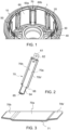
- Figure 1 shows a section of a typical wheel assembly comprising a wheel rim or tube well 1 having an outer diameter surface 10, on which a tyre (not shown) will usually be mounted, and an inner diameter surface 20 defining an interior cavity in which a brake assembly (not shown) will typically be arranged around a wheel hub 30.
- the hub 30 would be attached by bearing to an axle (not shown).
- the hub 30 is connected to the wheel rim 1 via a web 40.
- Rotor disc drive lugs (or torque bars) 50 extend axially across the tube well 1 for engagement with the brake discs.
- a heat shield is mounted to the inner diameter surface 20 of the wheel.
- the heat shield may be a single tubular shield or, as shown in this example, may be formed of several heat shield panels 60 provided between the rotor drive lugs 50.
- the heat shield/panels 60 is in the form of an arcuate thin metal sheet or several thin metal sheets and is attached to the wheel so as to be spaced apart from the wheel inner diameter surface by a small insulation gap (not shown).
- the heat shield is made of a number of panels or segments attached together, the adjoining edges 60a, 60b of the panels are connected and retained by means of retainers 70.
- the retainers 70 each define a seam between adjacent panels.
- a typical retainer 70 is shown in Figs. 2 and 3 .
- Such a retainer is formed of a shaped metal sheet having a main panel 70a that, in use, will define the seam between two adjacent heat shield panels when positioned between their adjacent edges 60a, 60b.
- the main panel 70a has a length I and a width w essentially corresponding to the dimensions of a drive lug 50.
- the top of the main panel is provided with a tab 61 within which is formed a hole 62 to receive a bolt or fastener (not shown).
- the other end of the main panel is provided with a foot 63 to support the retainer in place against the lug 50.
- the foot 63 may also have a hole 65 therethrough, in which an end pin of the lug can be located.
- cut-outs 66 are formed between the main panel and the foot. Extending along each of the long sides of the main panel is a side panel or wing 70b, 70b'. A bend 71 provides the transition from the main panel 70a to the wing 70b, 70b'.
- the retainer is located between adjacent edges of adjacent heat shield segments such that the wings extend over part of the respective segment to retain the segments to form the circular heat shield at the appropriate distance from the tube well.
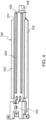
- Figure 4 shows a retainer 100 modified according to the disclosure to add stiffness and strength to the heat shield whilst minimising the thickness of the retainer in the space between the heat shield and the wheel, so reducing the effects of deformation or deflection of the panel, to avoid or mitigate the problems mentioned above.
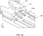
- the shape of the retainer is similar to that shown in Figs. 2 and 3 in that the retainer 100 is formed of a sheet of metal shaped to define an elongate central panel 101 flanked by two side panels or wings 102, 102'. Similarly to the known design, one end of the central panel is provided with a tab 103 through which a fastener hole 104 may be formed and the other end of the central panel is formed as a foot 105 which may have a hole 106 therethrough to retain a torque bar (not shown).
- the central panel being formed by a flat metal sheet as in the known design.
- additional stiffness may be provided to the weaker region between the central elongate panel and the wings by creating a U-shaped fold in the material between the central panel and the wing.
- the design of this disclosure modifies the existing design by providing reinforcing features onto the surface of the retainer, particularly on the central elongate panel, but possible also on the wings, at locations which are known to be vulnerable to deformation or deflection, to add strength and stiffness at those locations.
- the reinforcement features are in the form of strips or beads 200, 200a stamped onto the retainer sheet material. The beads or the like therefore add additional material at strategic locations to increase stiffness.
- the reinforcement features may have shapes other than strips or elongate beads, and may be e.g.
- the retainer may be provided along the whole length of the retainer e.g. extending along the whole length of the central elongate panel and/or the wings or may be provided as segments or portions along the length and/or width of the retainer.
- areas of particular weakness e.g. at the transitions to the tab or foot, or close to the edges of the central elongate panel can be identified and provided with reinforcement features.
- the depth and/or radius of the beads or the like can be varied to vary the resulting stiffness.
- the reinforcement features are formed as smooth U- or V-shaped stiffening beads.
- the retainer can be formed as a single piece, with the reinforcement features stamped onto the surface or attached by welding or adhesion or in other ways.
- the raised profile of the stiffening features can increase the surface area of the retainer and so improves its thermal properties.
- the central panel 101 is located at the seam between adjoining edges of adjacent panels and the side panels 102, 102'; extend partially across the respective heat shield panel to retain the heat shield panels in the heat shield configuration and spaced from the tube well by the insulation gap.
- the beading combine to increase the stiffness of the retainer, and so the depth of each individual beading can still be relatively small.
- the retainers in the space between the heat shield and the wheel rim therefore, have a relatively small profile and are thus less likely to contact the wheel rim if the panel is deformed or deflected than in conventional assemblies.
- the modified retainer does not, therefore, take up any additional space compared to the known design.
- each pair of adjacent heat shield panels is provided with a retainer between their adjoining edges.
- two or more retainers may be positioned between each pair of heat shield panels.
- the retainer of this disclosure provides additional strength to the heat shield and a secure connection between heat shield panels, whilst minimising the risk of wheel abrasion due to deformation or deflection of the panels.
Landscapes
- Engineering & Computer Science (AREA)
- Mechanical Engineering (AREA)
- General Engineering & Computer Science (AREA)
- Braking Arrangements (AREA)
- Physics & Mathematics (AREA)
- Thermal Sciences (AREA)
- Thermal Insulation (AREA)
Abstract
Description
- The present disclosure relates to a retainer for connecting panels or segments of a heat shield assembly for a wheel for a vehicle especially, but not exclusively, for an aircraft wheel.
- Wheels on aircraft and other vehicles are often provided with a brake assembly comprising a stack of brake discs mounted inside the wheel, within the tube well of the wheel. The brake operates by compressing the brake discs together to slow and stop rotation of the wheel. The friction between the pressed brake discs generates a large amount of heat which can cause damage to the wheel and/or tyres. It is conventional to provide a heat shield between the brake assembly and the wheel rim or tube well to reduce the effects of the heat generated by braking on the wheel parts. The heat shield can also catch hot brake material that is ejected from the brake discs during braking, before it strikes the wheel.
- Various types of heat shield are known but, typically, heat shields are in the form of metal sheets or panels provided concentric with the wheel tube well and spaced a small distance from the tube well. The heat shield can be provided as a single cylindrical piece but more typically is formed as a number of arcuate panels or segments that are attached together to form a complete cylindrical heat shield.
- Particularly with the increased use of carbon disc brakes, which have greater energy absorption capability than steel brakes and are significantly lighter, but which are larger than steel brake discs, it is important for the heat shields to be robust. There is, however, also a need for them to be as simple and lightweight as possible. In aircraft in particular, but also in other vehicles with braked wheels, there is a need to minimise the weight and size of the wheel assembly. Heat shields are therefore, often made of thin metal panels but may be arranged as two or more layers of panels with an insulation gap therebetween.
- Because of the high temperature and high stress/vibrational environments that braked wheels operate in and high centrifugal forces acting on the heat shields, as well as changes in tyre pressure, the heat shield can be caused to deform and/or deflect. This can cause high stresses on the heat shield and can cause the heat shield to come into contact with the wheel tube well which can, in turn, result in wheel abrasion. The connectors used to join adjacent panels comprise two engaging or interleaving hook parts resulting in a seam that is thicker than the individual panels themselves and the seams provide points around the heat shield that are even more likely to contact the wheel tube well during movement and/or if the heat shield panels are deflected or deformed. This is even more of an issue for carbon brakes because they are larger and so there is less space between the discs and the wheel. Flatter retainers have also been designed, that take the form of a central panel and side wings or panels. The central panel is provided with a hole at the top end through which a bolt can pass, and a foot at the bottom to be supported by a torque bar. The side panels extend partly across respective adjacent heat shield panels. The retainer and torque bar combine to connect/retain the heat shield panels. Such retainers are made of relatively thin sheets of metal to maintain a low profile. The retainer being thin, provides an area of weakness in the heat shield assembly, and is the area where the greatest deflection and plasticity appears. The retainer may not be strong enough to prevent deflection of the wings and the heat shield panels they support, in certain conditions. This can therefore lead to the heat shield panels making contact with the tube well, thus resulting in abrasion.
- There is a need for a heat shield assembly which is less prone to deflection and deforming and also an improved retainer, so as to avoid or reduce damage to the heat shield and to avoid or reduce wheel abrasion.
- According to the present disclosure, there is provided a retainer for connecting two panels of a heat shield assembly, the retainer comprising: a central elongate panel having a length I and a width w, a top end, a bottom end and first and second long sides extending from the top end to the bottom end; a first side panel extending along the first long side of the central elongate panel and a second side panel extending along the second long side of the central elongate panel; and wherein reinforcement features are applied to a surface of the central elongate panel.
- The assembly according to the disclosure will be described, by way of example only, with reference to the drawings. Variations and modifications are possible within the scope of the claims.
-
Figure 1 shows an example of a heat shield in a wheel. -
Figure 2 shows a conventional retainer forming the connection between heat shield panels as inFig. 1 . -
Figure 3 shows a profile view of a retainer as shown inFig. 2 . -
Figure 4 is a view of a retainer according to the disclosure. -
Figure 4A is a detail of the top end of a retainer as shown inFig. 4 . -
Figure 1 shows a section of a typical wheel assembly comprising a wheel rim or tube well 1 having anouter diameter surface 10, on which a tyre (not shown) will usually be mounted, and aninner diameter surface 20 defining an interior cavity in which a brake assembly (not shown) will typically be arranged around awheel hub 30. Thehub 30 would be attached by bearing to an axle (not shown). Thehub 30 is connected to thewheel rim 1 via aweb 40. Rotor disc drive lugs (or torque bars) 50 extend axially across the tube well 1 for engagement with the brake discs. - To protect the
wheel rim 1 from the heat generated during hard braking or from brake disc material ejected during braking, a heat shield is mounted to theinner diameter surface 20 of the wheel. The heat shield may be a single tubular shield or, as shown in this example, may be formed of severalheat shield panels 60 provided between therotor drive lugs 50. The heat shield/panels 60 is in the form of an arcuate thin metal sheet or several thin metal sheets and is attached to the wheel so as to be spaced apart from the wheel inner diameter surface by a small insulation gap (not shown). Where the heat shield is made of a number of panels or segments attached together, theadjoining edges retainers 70. Theretainers 70 each define a seam between adjacent panels. - A
typical retainer 70 is shown inFigs. 2 and 3 . Such a retainer is formed of a shaped metal sheet having amain panel 70a that, in use, will define the seam between two adjacent heat shield panels when positioned between theiradjacent edges main panel 70a has a length I and a width w essentially corresponding to the dimensions of adrive lug 50. The top of the main panel is provided with atab 61 within which is formed ahole 62 to receive a bolt or fastener (not shown). The other end of the main panel is provided with a foot 63 to support the retainer in place against thelug 50. The foot 63 may also have ahole 65 therethrough, in which an end pin of the lug can be located. Typically, cut-outs 66 are formed between the main panel and the foot. Extending along each of the long sides of the main panel is a side panel orwing bend 71 provides the transition from themain panel 70a to thewing - In use, the retainer is located between adjacent edges of adjacent heat shield segments such that the wings extend over part of the respective segment to retain the segments to form the circular heat shield at the appropriate distance from the tube well.
- As mentioned above, in the harsh braking conditions experienced by e.g. wheels on an aircraft landing gear, high temperatures are reached and pieces of hot material can break off from the rotor discs. All of this can cause the heat shield panels to deform or deflect and be damaged and/or to contact the wall by being deflected into the insulation gap between the heat shield and the tube well interior surface. Because the retainer is made of relatively thin, light material, deformation of the panels can cause the retainer to deflect outwards and contact the wheel rim and this can result in damage and wheel abrasion. Also, if the retainers are not sufficiently strong to retain the heat shield panels in such conditions, the heat shield panels themselves can also contact the wheel. This can cause wheel abrasion and/or heat shield damage/abrasion and require the entire wheel assembly to be replaced.
-
Figure 4 shows aretainer 100 modified according to the disclosure to add stiffness and strength to the heat shield whilst minimising the thickness of the retainer in the space between the heat shield and the wheel, so reducing the effects of deformation or deflection of the panel, to avoid or mitigate the problems mentioned above. - As shown in
Fig. 4 , the shape of the retainer is similar to that shown inFigs. 2 and 3 in that theretainer 100 is formed of a sheet of metal shaped to define an elongatecentral panel 101 flanked by two side panels orwings 102, 102'. Similarly to the known design, one end of the central panel is provided with atab 103 through which afastener hole 104 may be formed and the other end of the central panel is formed as afoot 105 which may have ahole 106 therethrough to retain a torque bar (not shown). The central panel being formed by a flat metal sheet as in the known design. In an example, although not essential, additional stiffness may be provided to the weaker region between the central elongate panel and the wings by creating a U-shaped fold in the material between the central panel and the wing. The design of this disclosure modifies the existing design by providing reinforcing features onto the surface of the retainer, particularly on the central elongate panel, but possible also on the wings, at locations which are known to be vulnerable to deformation or deflection, to add strength and stiffness at those locations. In the example shown, the reinforcement features are in the form of strips orbeads - In one particular example, the reinforcement features are formed as smooth U- or V-shaped stiffening beads.
- The retainer can be formed as a single piece, with the reinforcement features stamped onto the surface or attached by welding or adhesion or in other ways.
- In addition to adding strength to the retainer, the raised profile of the stiffening features can increase the surface area of the retainer and so improves its thermal properties.
- In use, the
central panel 101 is located at the seam between adjoining edges of adjacent panels and theside panels 102, 102'; extend partially across the respective heat shield panel to retain the heat shield panels in the heat shield configuration and spaced from the tube well by the insulation gap. With the added stiffness and strength provided by the beading, if the heat shield panels deflect, the retainer will be strong and stiff enough to retain the heat shield panels away from the inner diameter of the tube well without the retainer or the heat shield panels contacting the wheel and causing abrasion. - The beading combine to increase the stiffness of the retainer, and so the depth of each individual beading can still be relatively small. The retainers in the space between the heat shield and the wheel rim, therefore, have a relatively small profile and are thus less likely to contact the wheel rim if the panel is deformed or deflected than in conventional assemblies. The modified retainer does not, therefore, take up any additional space compared to the known design.
- In an example, each pair of adjacent heat shield panels is provided with a retainer between their adjoining edges. In other examples, two or more retainers may be positioned between each pair of heat shield panels.
- To assemble the heat shield, two adjacent panels are connected by means of the retainer.
- The retainer of this disclosure provides additional strength to the heat shield and a secure connection between heat shield panels, whilst minimising the risk of wheel abrasion due to deformation or deflection of the panels.
Claims (15)
- A retainer for connecting two panels of a heat shield assembly, the retainer comprising: a central elongate panel (101) having a length I and a width w, a top end, a bottom end and first and second long sides extending from the top end to the bottom end; a first side panel (102) extending along the first long side of the central elongate panel and a second side panel (102') extending along the second long side of the central elongate panel; and wherein reinforcement features (200, 200a) are applied to a surface of the central elongate panel.
- The retainer of claim 1, further comprising a tab (103) extending from the top end.
- The retainer of claim 2, further comprising a fastening hole (104) formed in the tab (103).
- The retainer of any preceding claim, further comprising a foot (105) at the bottom end.
- The retainer of claim 4, further comprising a locating hole (106) in the foot (105).
- The retainer of any preceding claim, the central panel and the first and second side panels being formed from a single piece of sheet metal.
- The retainer of any preceding claim, wherein the reinforcement features (200, 200a) are in the form of beads stamped onto the surface of the retainer.
- The retainer of any preceding claim, wherein the reinforcement features extend along the length of the retainer.
- The retainer of any of claims 1 to 7, wherein the reinforcement means are provided at discrete locations on the surface of the retainer.
- A heat shield assembly for a wheel assembly, comprising a plurality of arcuate heat shield panels (60) arranged to be connected together to form a heat shield to be attached to the interior of a wheel, and a retainer as claimed in any preceding claim, for attaching adjacent panels.
- The heat shield assembly as claimed in claim 10, wherein one or more retainers is provided between each pair of adjacent panels.
- The heat shield assembly of claim 10 or 11, wherein each panel comprises two heat shield panel layers arranged radially adjacent each other and wherein a retainer prevents relative movement of the layers.
- A wheel assembly comprising a wheel rim having a radially inner surface and a radially outer surface, and a heat shield assembly as claimed in claim 10, 11 or 12, attached to and having a radially outer surface radially spaced from the radially inner surface of the wheel rim.
- The wheel assembly of claim 13, further comprising a plurality of torque bars (50) arranged around the radially inner surface of the heat shield, a torque bar positioned along the central elongate panel of each retainer.
- The wheel assembly of claims 13 or 14, being a wheel assembly for the landing gear of an aircraft.
Priority Applications (2)
| Application Number | Priority Date | Filing Date | Title |
|---|---|---|---|
| EP22461570.8A EP4289638A1 (en) | 2022-06-09 | 2022-06-09 | Heat shield panel retainer |
| US18/325,849 US12459312B2 (en) | 2022-06-09 | 2023-05-30 | Heat shield panel retainer |
Applications Claiming Priority (1)
| Application Number | Priority Date | Filing Date | Title |
|---|---|---|---|
| EP22461570.8A EP4289638A1 (en) | 2022-06-09 | 2022-06-09 | Heat shield panel retainer |
Publications (1)
| Publication Number | Publication Date |
|---|---|
| EP4289638A1 true EP4289638A1 (en) | 2023-12-13 |
Family
ID=82019407
Family Applications (1)
| Application Number | Title | Priority Date | Filing Date |
|---|---|---|---|
| EP22461570.8A Pending EP4289638A1 (en) | 2022-06-09 | 2022-06-09 | Heat shield panel retainer |
Country Status (2)
| Country | Link |
|---|---|
| US (1) | US12459312B2 (en) |
| EP (1) | EP4289638A1 (en) |
Citations (3)
| Publication number | Priority date | Publication date | Assignee | Title |
|---|---|---|---|---|
| EP1304240A1 (en) * | 2001-10-10 | 2003-04-23 | Goodrich Corporation | Heat shield assembly for aircraft wheel and brake assembly |
| EP3712054A1 (en) * | 2019-03-19 | 2020-09-23 | Goodrich Corporation | Covered retainer for segmented annular heat shield |
| EP3767125A1 (en) * | 2019-07-16 | 2021-01-20 | Goodrich Corporation | Heat shield retainer and methods |
Family Cites Families (3)
| Publication number | Priority date | Publication date | Assignee | Title |
|---|---|---|---|---|
| US4084857A (en) | 1976-12-20 | 1978-04-18 | The Bendix Corporation | Drive key heat shield and support for wheel rim heat shield of multiple disc brake |
| US11713111B2 (en) | 2019-03-19 | 2023-08-01 | Goodrich Corporation | Retainer for segmented annular heat shield |
| EP4289637B1 (en) * | 2022-06-09 | 2025-02-19 | Goodrich Corporation | Heat shield panel retainer |
-
2022
- 2022-06-09 EP EP22461570.8A patent/EP4289638A1/en active Pending
-
2023
- 2023-05-30 US US18/325,849 patent/US12459312B2/en active Active
Patent Citations (3)
| Publication number | Priority date | Publication date | Assignee | Title |
|---|---|---|---|---|
| EP1304240A1 (en) * | 2001-10-10 | 2003-04-23 | Goodrich Corporation | Heat shield assembly for aircraft wheel and brake assembly |
| EP3712054A1 (en) * | 2019-03-19 | 2020-09-23 | Goodrich Corporation | Covered retainer for segmented annular heat shield |
| EP3767125A1 (en) * | 2019-07-16 | 2021-01-20 | Goodrich Corporation | Heat shield retainer and methods |
Also Published As
| Publication number | Publication date |
|---|---|
| US20230408215A1 (en) | 2023-12-21 |
| US12459312B2 (en) | 2025-11-04 |
Similar Documents
| Publication | Publication Date | Title |
|---|---|---|
| EP0555822B1 (en) | Heatshield installation for aircraft brake | |
| EP3647622B1 (en) | Segmented heat shield with reduced interlayer thermal conduction | |
| US12558928B2 (en) | Heat shield panel retainer | |
| EP3750720B1 (en) | Vehicle wheel for passenger cars | |
| US12459312B2 (en) | Heat shield panel retainer | |
| EP4289636B1 (en) | Heat shield panel retainer | |
| CA1048947A (en) | Rim construction for wheels having brake torque drives | |
| US20240270374A1 (en) | Heat shield assembly | |
| EP4293246B1 (en) | Rotor clip for brake assembly | |
| US12486028B2 (en) | Heat shield panel connector | |
| EP4321769A1 (en) | Heat shield panel | |
| EP4290094B1 (en) | Rotor clip for brake assembly and method of fittig a clip assembly | |
| EP4155570B1 (en) | Rotor clip for brake assembly | |
| EP4155571B1 (en) | Heat shield panel attachment bracket | |
| EP4155572B1 (en) | Heat shield assembly for wheel and wheel with heat shield assembly | |
| EP4403790B1 (en) | Heat shield assembly | |
| US4000791A (en) | Disk brake for reinforced drive key member | |
| US12486877B2 (en) | Rotor clip for brake assembly |
Legal Events
| Date | Code | Title | Description |
|---|---|---|---|
| PUAI | Public reference made under article 153(3) epc to a published international application that has entered the european phase |
Free format text: ORIGINAL CODE: 0009012 |
|
| STAA | Information on the status of an ep patent application or granted ep patent |
Free format text: STATUS: THE APPLICATION HAS BEEN PUBLISHED |
|
| AK | Designated contracting states |
Kind code of ref document: A1 Designated state(s): AL AT BE BG CH CY CZ DE DK EE ES FI FR GB GR HR HU IE IS IT LI LT LU LV MC MK MT NL NO PL PT RO RS SE SI SK SM TR |
|
| STAA | Information on the status of an ep patent application or granted ep patent |
Free format text: STATUS: REQUEST FOR EXAMINATION WAS MADE |
|
| 17P | Request for examination filed |
Effective date: 20240613 |
|
| RBV | Designated contracting states (corrected) |
Designated state(s): AL AT BE BG CH CY CZ DE DK EE ES FI FR GB GR HR HU IE IS IT LI LT LU LV MC MK MT NL NO PL PT RO RS SE SI SK SM TR |
|
| STAA | Information on the status of an ep patent application or granted ep patent |
Free format text: STATUS: EXAMINATION IS IN PROGRESS |
|
| 17Q | First examination report despatched |
Effective date: 20240904 |