EP4289627A1 - Fluid ejection device and handheld fluid ejection device - Google Patents
Fluid ejection device and handheld fluid ejection device Download PDFInfo
- Publication number
- EP4289627A1 EP4289627A1 EP23174236.2A EP23174236A EP4289627A1 EP 4289627 A1 EP4289627 A1 EP 4289627A1 EP 23174236 A EP23174236 A EP 23174236A EP 4289627 A1 EP4289627 A1 EP 4289627A1
- Authority
- EP
- European Patent Office
- Prior art keywords
- fluid ejection
- revolving
- maintenance station
- ejection head
- housing
- Prior art date
- Legal status (The legal status is an assumption and is not a legal conclusion. Google has not performed a legal analysis and makes no representation as to the accuracy of the status listed.)
- Pending
Links
Images






Classifications
-
- B—PERFORMING OPERATIONS; TRANSPORTING
- B05—SPRAYING OR ATOMISING IN GENERAL; APPLYING FLUENT MATERIALS TO SURFACES, IN GENERAL
- B05B—SPRAYING APPARATUS; ATOMISING APPARATUS; NOZZLES
- B05B15/00—Details of spraying plant or spraying apparatus not otherwise provided for; Accessories
- B05B15/50—Arrangements for cleaning; Arrangements for preventing deposits, drying-out or blockage; Arrangements for detecting improper discharge caused by the presence of foreign matter
- B05B15/52—Arrangements for cleaning; Arrangements for preventing deposits, drying-out or blockage; Arrangements for detecting improper discharge caused by the presence of foreign matter for removal of clogging particles
-
- B—PERFORMING OPERATIONS; TRANSPORTING
- B41—PRINTING; LINING MACHINES; TYPEWRITERS; STAMPS
- B41J—TYPEWRITERS; SELECTIVE PRINTING MECHANISMS, i.e. MECHANISMS PRINTING OTHERWISE THAN FROM A FORME; CORRECTION OF TYPOGRAPHICAL ERRORS
- B41J2/00—Typewriters or selective printing mechanisms characterised by the printing or marking process for which they are designed
- B41J2/005—Typewriters or selective printing mechanisms characterised by the printing or marking process for which they are designed characterised by bringing liquid or particles selectively into contact with a printing material
- B41J2/01—Ink jet
- B41J2/135—Nozzles
- B41J2/165—Prevention or detection of nozzle clogging, e.g. cleaning, capping or moistening for nozzles
- B41J2/16517—Cleaning of print head nozzles
- B41J2/16535—Cleaning of print head nozzles using wiping constructions
- B41J2/16544—Constructions for the positioning of wipers
- B41J2/16547—Constructions for the positioning of wipers the wipers and caps or spittoons being on the same movable support
-
- B—PERFORMING OPERATIONS; TRANSPORTING
- B05—SPRAYING OR ATOMISING IN GENERAL; APPLYING FLUENT MATERIALS TO SURFACES, IN GENERAL
- B05B—SPRAYING APPARATUS; ATOMISING APPARATUS; NOZZLES
- B05B15/00—Details of spraying plant or spraying apparatus not otherwise provided for; Accessories
- B05B15/14—Arrangements for preventing or controlling structural damage to spraying apparatus or its outlets, e.g. for breaking at desired places; Arrangements for handling or replacing damaged parts
-
- B—PERFORMING OPERATIONS; TRANSPORTING
- B08—CLEANING
- B08B—CLEANING IN GENERAL; PREVENTION OF FOULING IN GENERAL
- B08B1/00—Cleaning by methods involving the use of tools
- B08B1/10—Cleaning by methods involving the use of tools characterised by the type of cleaning tool
- B08B1/14—Wipes; Absorbent members, e.g. swabs or sponges
- B08B1/143—Wipes
-
- B—PERFORMING OPERATIONS; TRANSPORTING
- B41—PRINTING; LINING MACHINES; TYPEWRITERS; STAMPS
- B41J—TYPEWRITERS; SELECTIVE PRINTING MECHANISMS, i.e. MECHANISMS PRINTING OTHERWISE THAN FROM A FORME; CORRECTION OF TYPOGRAPHICAL ERRORS
- B41J2/00—Typewriters or selective printing mechanisms characterised by the printing or marking process for which they are designed
- B41J2/005—Typewriters or selective printing mechanisms characterised by the printing or marking process for which they are designed characterised by bringing liquid or particles selectively into contact with a printing material
- B41J2/01—Ink jet
- B41J2/135—Nozzles
- B41J2/165—Prevention or detection of nozzle clogging, e.g. cleaning, capping or moistening for nozzles
- B41J2/16505—Caps, spittoons or covers for cleaning or preventing drying out
- B41J2/16508—Caps, spittoons or covers for cleaning or preventing drying out connected with the printer frame
-
- B—PERFORMING OPERATIONS; TRANSPORTING
- B41—PRINTING; LINING MACHINES; TYPEWRITERS; STAMPS
- B41J—TYPEWRITERS; SELECTIVE PRINTING MECHANISMS, i.e. MECHANISMS PRINTING OTHERWISE THAN FROM A FORME; CORRECTION OF TYPOGRAPHICAL ERRORS
- B41J2/00—Typewriters or selective printing mechanisms characterised by the printing or marking process for which they are designed
- B41J2/005—Typewriters or selective printing mechanisms characterised by the printing or marking process for which they are designed characterised by bringing liquid or particles selectively into contact with a printing material
- B41J2/01—Ink jet
- B41J2/135—Nozzles
- B41J2/165—Prevention or detection of nozzle clogging, e.g. cleaning, capping or moistening for nozzles
- B41J2/16517—Cleaning of print head nozzles
- B41J2/16535—Cleaning of print head nozzles using wiping constructions
- B41J2/16538—Cleaning of print head nozzles using wiping constructions with brushes or wiper blades perpendicular to the nozzle plate
-
- B—PERFORMING OPERATIONS; TRANSPORTING
- B41—PRINTING; LINING MACHINES; TYPEWRITERS; STAMPS
- B41J—TYPEWRITERS; SELECTIVE PRINTING MECHANISMS, i.e. MECHANISMS PRINTING OTHERWISE THAN FROM A FORME; CORRECTION OF TYPOGRAPHICAL ERRORS
- B41J3/00—Typewriters or selective printing or marking mechanisms characterised by the purpose for which they are constructed
- B41J3/36—Typewriters or selective printing or marking mechanisms characterised by the purpose for which they are constructed for portability, i.e. hand-held printers or laptop printers
Definitions
- the disclosure pertains to a revolving maintenance station for cleaning and sealing a fluid ejection head of a fluid ejection device.
- Fluid jet ejection relies on ejecting miniscule droplets of a jetting fluid from the face of a fluid jet ejection head which is in fluidic communication with a fluid reservoir of the jetting fluid contained in the body of a fluid ejection device.
- Fluid jet ejection heads require "servicing" of a chip face of the ejection head including wiping and capping the chip face to maintain the operability of the fluid jet ejection head. Wiping the chip face removes dust, fluid spray, and crusting from a nozzle plate of the fluid jet ejection head which can negatively impact jetting performance. Once wiped, the chip face of the ejection head must be sealed or “capped” to prevent evaporation of the jetting fluid from nozzles in the nozzle plate which could lead to depriming of the fluid jet ejection head.
- the printhead is housed in a printer that moves the printhead in a linear motion across the substrate, with the substrate being moved perpendicularly to the motion of the printhead to create a two-dimensional image on the substrate.
- the servicing method is well established and typically includes moving the printhead in a linear motion during printing and, once a print job has been completed, moving the printhead further in a linear direction to a service station where the printhead is driven across a wiping blade to remove debris. Once wiped, the printhead moves linearly further to a capping station where the chip face of the printhead is sealed.
- the service station and capping station in a conventional desktop printer are typically laterally adjacent to one another.
- an embodiment of the disclosure provides a fluid ejection device that includes a housing, a fluid reservoir disposed in the housing and a fluid ejection head.
- a revolving maintenance station that includes an ejection head wiper and an ejection head capping device is movably attached to the housing and is configured for rotation to selectively position the ejection head wiper or the ejection head capping device adjacent to the fluid ejection head.
- a handheld fluid ejection device that includes a housing, a fluid reservoir disposed in the housing and a fluid ejection head.
- a revolving maintenance station is provided and includes an ejection head wiper, an ejection head capping device, and a fluid ejection port therein.
- the revolving maintenance station is movably attached to the housing and is configured for rotation to selectively position the ejection head wiper, the ejection head capping device, or the fluid ejection port adjacent to the fluid ejection head.
- the ejection head capping device is configured to protect the fluid ejection head and to maintain an environment adjacent to the fluid ejection head that prevents fluid from evaporating therefrom.
- the ejection head capping device includes a vent hole therein.
- the revolving maintenance station further includes at least one tab on an inside wall thereof.
- the housing includes a circular wall having at least one groove on an outside portion thereof for mating with the at least one tab of the revolving maintenance station.
- the revolving maintenance station is configured to be manually rotated relative to the housing. In other embodiments, the revolving maintenance station is configured to be automatically rotated relative to the housing.
- the ejection head wiper includes an elastomeric wiper blade.
- the ejection head capping devices is an elastomeric capping device.
- the revolving maintenance station further includes an absorbent wiper blade.
- the revolving maintenance station further includes a fluid ejection port therein.
- the revolving maintenance station further comprises at least one V-shaped tab on an inside wall thereof.
- the housing includes a circular wall having at least one V-shaped groove on an outside portion thereof for mating with the at least one V-shaped tab of the revolving maintenance station.
- the revolving maintenance station is biased toward the housing.
- the claimed maintenance station may include all of the components necessary to prevent an ejection head from drying out or clogging and the maintenance station can be easily operated manually or automatically to maintain the performance of the fluid ejection device.
- the apparatus of the disclosed embodiments features an additional axis of motion perpendicular to the face of the fluid ejection head, thereby allowing an ejection head capping device to be positioned above and then lowered onto the face of the fluid ejection head.
- the capping device also provides a mechanism to ensure a secure seal between the capping device and the ejection head.
- the wiper blade is isolated from the fluid ejection head after the ejection head is wiped.
- the wiper blade may alternatively be positioned over a station where excess fluid can drip therefrom and be captured, or the wiper blade may be dragged across an absorbent material after wiping the face of the fluid ejection head so that any excess fluid is removed from the wiper blade.
- embodiments of the disclosure may prevent tacky fluids from remaining in contact with the face of the fluid ejection head since, after use, the wiper blade is isolated from the fluid ejection head unlike some conventional wipers.
- a handheld fluid ejection device 10 that includes a revolving maintenance station 12.
- the maintenance station includes a wiper, an ejection head capping structure, and a fluid ejection port 14.
- the maintenance station 12 is rotatable about a circular wall 16 attached to the housing 18 in the direction of arrow 20 to provide wiping, ejection head capping and fluid ejection functions.
- Handheld fluid ejection devices 10 are used for a variety of applications including, but not limited to, printing, lubrication, pharmaceutical delivery, vapor devices and the like.
- the fluid ejection devices are typically self-contained devices that include the housing 18, a fluid reservoir 22, a control circuit board 24, and a power supply 26.
- FIG. 2 is an end perspective view of the fluid ejection device 10 with a molding for the revolving maintenance station 12 removed thereby exposing a fluid ejection head 28.
- the revolving maintenance station 12 is rotated to a fluid ejection orientation
- the fluid ejection head 28 is adjacent to the fluid ejection port 14.
- FIG. 4 is an end perspective view of the fluid ejection device 10 wherein the revolving maintenance station 12 is rotated to an ejection head capping orientation.
- the revolving maintenance station 12 may be mated to the circular wall 16 attached to the housing 18 of the handheld fluid ejection device 10 in a variety of ways.
- a first embodiment is shown in Figures 5-11 , where the revolving maintenance station 12 includes tabs 30 ( FIG. 6 ) extruded on an inner wall 32 thereof which can be fitted into grooves 34 on the outer wall 36 of the circular wall 16. It would be apparent to one skilled in the art that alternatively, tabs may be placed on the outer wall 36 of the housing 18 and that the grooves may be provided on the inner wall 32 of the revolving maintenance station 12.
- the grooves 34 in the outer wall 36 of the housing 18 enable for the revolving maintenance station 12 to rotate around the circumference of the circular wall 16 and to be seated in the appropriate locations for either fluid ejection or for capping the fluid ejection head 28 with an ejection head capping device 38.
- the tabs 30 may include circular tabs 30a and rectangular tabs 30b on the revolving maintenance station 12 that mate with particular grooves 34 on the outer wall 36 of the housing 18 so that either the ejection head capping device 38 or the fluid ejection port 14 is adjacent to the fluid ejection head 28.
- a race 40 is provided in the circular wall 16 for retaining the tabs 30 therein.
- Slots 42 in a retainer ring 44 enable the revolving maintenance station 12 to be removed from the circular wall 16 for reconditioning components of the revolving maintenance station 12.
- a noteworthy feature of revolving maintenance station 12 is that the maintenance station 12 is readily replaceable so that the wiper blade 46 and capping device do not become excessively degraded. Either the entire maintenance station assembly can be replaced, or the maintenance station 12 may be designed so that only the wiper blade 46 and capping device 38 are replaceable while maintaining the main body of the maintenance station 12. Interchangeable wiper blades 46 and capping devices 38 provide an economical and environmental benefit for both the user and manufacturer.
- the wiper blade 46 may be removably attached to a wiper blade holder 48 and the ejection head capping device 38 may be removably attached to a capping device holder 50 by a user so that the capping and wiping operations may be maintained throughout the life of the handheld fluid jet ejection device 10.
- Each of the wiper blade 46 and ejection head capping device 38 may be made of a resilient elastomeric material that provides suitable wiping and sealing characteristics.
- the wiper blade 46 and capping device 38 are made of a natural or synthetic rubber. Accordingly, the wiper blade 46 is positioned so that, when the maintenance station 12 is in the operating position, rotating the maintenance station 12 results in engagement of the wiper blade 46 with the face of the fluid ejection head 28 thereby removing debris or excess fluid before the fluid ejection head 28 is capped.
- the wiper blade 46 is positioned so that rotating the station in either direction provides the cleaning action desired before capping.
- a unidirectional rather than a bi-directional wiping motion is provided.
- Unidirectional wiping prevents the chance that a return wipe across the ejection head 28 could result in recontamination of the ejection head 28 with debris from the wiper blade 46.
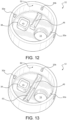
- a ratchet-like mechanism may be provided to ensure that the maintenance station 12 is only rotated in a single direction so that the wiping is unidirectional. The single direction of rotation allows for the size of the wiper blade 46 to be reduced and placed on only a single side of the maintenance station 12 between the fluid ejection port 14 and the capping device 38 as shown in FIG. 12 .
- a wiper 52 made of an absorbent material may be placed opposite of the wiper blade 46 as shown in FIG. 13 .
- the absorbent wiper 52 may engage the face of the ejection head 28 prior to aligning the fluid ejection port 14 with the ejection head 28 and prior to operating the device.
- the absorbent properties of the absorbent wiper 52 may be used to prime the ejection head 28 by providing a wicking action with respect to the fluid to be ejected. Accordingly, the absorbent wiper 52 may be made in various sizes to increase the duration of contact with the ejection head 28.
- An absorbent wiper 52, as described above, would be impractical to implement in a conventional maintenance station, where an absorbent blade could only appear in series with the wiping blade.
- ejection head capping device 38 may seal directly onto a face of fluid ejection head 28 or may encompass an entirety of fluid ejection head 28. Accordingly, the ejection head capping device 38 is meant to provide protection for the fluid ejection head 28 and to maintain a locally humid environment to prevent evaporation of the jetting fluid from nozzles of fluid ejection head 28.
- the ejection head capping device 38 may also feature a vent hole 55 therein to relieve pressure on the fluid ejection head 28 when seating the capping device 38 into a resting position over fluid ejection head 28.
- a vent 54 communicated with outside may be formed on a top surface of the maintenance station 12. The vent 54, as shown in FIG.
- vent 54 may also provide an airflow path with the vent hole 55 of the ejection head capping device 38 from an outside ambient atmosphere into the fluid ejection head 28 so that when a fluid is jetted a vacuum does not form inside the revolving maintenance station 12.
- vent 54 is sufficiently small so that the humidity inside the capping device 38 remains relatively high.
- indicia 56 may be provided on the housing 18 to indicate the position of the revolving maintenance station 12.
- indicator marks located on the housing 18 and corresponding indicia 56 located on an outer wall of the maintenance station 12 may help the user identify the correct rotational positioning of the maintenance station 12 with respect to the ejection head 28.
- Other means of indicating the correct position such as multi-colored or flashing lights, or audible cues may be used alone or in combination to alert a user of the correct positioning of the maintenance station 12. Errors in positioning of the maintenance station 12 may also be indicated by any of the foregoing indicia, lights or sounds.
- the revolving maintenance station 12 may be operated to an extended position ( FIG. 7 ) and retracted into a resting position ( FIG. 8 ) with the ejection head capping device 38 adjacent to the fluid ejection head 28.
- the revolving maintenance station may also be extended ( FIG. 9 ) and rotated into an operating position ( FIG. 10 ) with the fluid ejection port 14 adjacent to the fluid ejection head 28.
- the revolving maintenance station may again be extended ( FIG. 9 ) and rotated back to the resting position ( FIG. 8 ) while the wiper blade 46 sweeps across the fluid ejection head 28 as shown in FIG. 11 .
- the foregoing revolving maintenance station may be manually extended, rotated, and retracted by a user.
- the revolving maintenance station 12 may be extended and retracted in a direction perpendicular to a face of the fluid ejection head 28.
- the revolving maintenance station 12 is designed so that it must be extended before rotation, or the revolving maintenance station 12 may be designed so that rotation drives the extension of the revolving maintenance station 12 such as by providing V-shaped grooves and V-shaped tabs.
- a central shaft 58 having a first end mounted to the housing 18 and a second end that extends beyond the circular wall 16 may be provided.
- the first end of the central shaft 58 may be affixed to a stopper 60 and the second end of the central shaft may be mated to a hole or boss 62 located at the center of the revolving maintenance station 64.
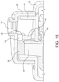
- Upper and lower limits for the stopper are provided to enable vertical travel of the revolving maintenance station 64 so that the revolving maintenance station 64 may be extended ( FIG. 14 ) and retracted into a resting position ( FIG. 15 ) with the ejection head capping device 38 adjacent to the fluid ejection head 28.
- FIG. 14 the revolving maintenance station 64
- the revolving maintenance station 64 may be extended and rotated while the wiper blade 46 sweeps across the fluid ejection head 28.
- the foregoing revolving maintenance station may be manually extended, rotated, and retracted by a user.
- FIG. 17 is an inside perspective view of the revolving maintenance station 64 and central shaft 58.
- One or more embedded magnets 66 may be provided on a circumferential edge 68 of the maintenance station 64 to aid in aligning the maintenance station 64 with the housing 70 of the fluid ejection device.
- the housing 70 may include magnets 72 or metal inserts as shown in FIG. 18 to maintain proper positioning and alignment of the revolving maintenance station 64.
- the housing 74 may be provided as shown in FIG. 19 without the circular wall 16.
- the central shaft 76 is attached to a stepper motor 78 ( FIG. 20 ) rather than floating inside the housing 70 for use in repositioning the revolving maintenance station 64.
- the stepper motor 78 enables radial motion of the revolving maintenance station 64.
- the stepper motor 78 may also be mounted to a linear actuator 80 to provide motion of the revolving maintenance station 64 in a direction coaxial to the central shaft 76 to enable the revolving maintenance station 64 to be lifted before rotating to its next position and then reseated.
- the linear actuator 80 is provided with enough torque to overcome the resistance of the magnets 66 and 72 holding the maintenance station 64 in a resting position.
- the linear actuator 80 and stepper motor 78 may also be designed to hold the position of the revolving maintenance station 64 until activated by a user or could be used in conjunction with the tabs 30 and groove 34 or magnets 66 and 72 to maintain the correct position of the revolving maintenance station 64. It is conceivable that the linear actuator 80 may be programmed to apply a downward force while the wiper blade 46 is moving across the face of the fluid ejection head 28 to ensure engagement between the fluid ejection head 28 and the wiper blade 46.
- the linear actuator 80 may be paired with a force sensor so that a predetermined amount of force can be applied to the fluid ejection head 28 by the wiper blade 46 to help alleviate any error in manufacturing tolerances or degradation of the wiper blade 46 over time.
- the automatic maintenance station may be programmed to only rotate in a single direction.
- revolving maintenance station and its compact design are primarily aimed towards handheld fluid ejection devices, it is also conceivable that the revolving maintenance station described herein could be used in larger, stationary fluid ejection devices. Such a maintenance station would likely not require a fluid ejection port, as these devices typically translate the fluid ejection head to a desired fluid ejection location. Once an ejection head reaches its home position, a revolving maintenance station may be used to wipe and cap the ejection head using the actuating and rotating mechanisms as described above for the automatic maintenance station for a handheld fluid ejection device.
- the maintenance station may exist without a fluid ejection port for larger, stationary fluid ejection devices
- a fluid ejection port through which fluid can be dispensed
- the fluid ejection port may also feature various means by which to attach various diffusers and adapters to modify the behavior and flow of the jetted fluid. Such means may include clips, press fits, snap fits, threading, or magnets.
- the disclosed embodiments provide an apparatus and method for using a revolving maintenance station to wipe and cap the fluid ejection head.
- the handheld fluid ejection device includes only a few components: the revolving maintenance station, a fluid ejection head, a housing, a fluid reservoir, a circuit board and a power supply.
- the fluid ejection head and fluid reservoir are housed in the body of the housing all with all the electrical components necessary to operate the fluid ejection head.
- the embodiment shown in the figures demonstrates a round maintenance station, it is appreciated that one skilled in the art could envision similar devices featuring a maintenance station using various shapes or sizes.
- the unique characteristic of the disclosed embodiments pertains to the revolving nature of the mechanism, which allows for a compact arrangement of the components necessary for fluid ejection head maintenance.
- the mechanism may be manually or automatically actuated by the user and contains readily replaceable and maintainable components.
- the revolving maintenance station features a built-in fluid ejection port so that the ejection head does not need to be translated to a separate position before dispensing a fluid.
- the currently disclosed apparatus acts as both the maintenance station and a storage housing for the fluid ejection head. As the maintenance station is rotated, multiple maintenance steps may be placed in series around the inside wall of the maintenance station to aid in both priming and cleaning the fluid ejection head.
Landscapes
- Ink Jet (AREA)
- Details Or Accessories Of Spraying Plant Or Apparatus (AREA)
Abstract
Description
- The disclosure pertains to a revolving maintenance station for cleaning and sealing a fluid ejection head of a fluid ejection device.
- Fluid jet ejection relies on ejecting miniscule droplets of a jetting fluid from the face of a fluid jet ejection head which is in fluidic communication with a fluid reservoir of the jetting fluid contained in the body of a fluid ejection device. Fluid jet ejection heads require "servicing" of a chip face of the ejection head including wiping and capping the chip face to maintain the operability of the fluid jet ejection head. Wiping the chip face removes dust, fluid spray, and crusting from a nozzle plate of the fluid jet ejection head which can negatively impact jetting performance. Once wiped, the chip face of the ejection head must be sealed or "capped" to prevent evaporation of the jetting fluid from nozzles in the nozzle plate which could lead to depriming of the fluid jet ejection head.
- Traditionally inkjet printing has been used to print images and text onto various substrates. The printhead is housed in a printer that moves the printhead in a linear motion across the substrate, with the substrate being moved perpendicularly to the motion of the printhead to create a two-dimensional image on the substrate. On typical inkjet printer systems, such as a desktop printer, the servicing method is well established and typically includes moving the printhead in a linear motion during printing and, once a print job has been completed, moving the printhead further in a linear direction to a service station where the printhead is driven across a wiping blade to remove debris. Once wiped, the printhead moves linearly further to a capping station where the chip face of the printhead is sealed. The service station and capping station in a conventional desktop printer are typically laterally adjacent to one another.
- As fluid jet technology moves into new industries the ejection head may now be housed in small handheld devices where it is not possible to use traditional maintenance devices and methods. Accordingly, what is needed is a maintenance station or device that is not dependent on movement of a fluid ejection head laterally to a remote location for maintenance.
- Accordingly, an embodiment of the disclosure provides a fluid ejection device that includes a housing, a fluid reservoir disposed in the housing and a fluid ejection head. A revolving maintenance station that includes an ejection head wiper and an ejection head capping device is movably attached to the housing and is configured for rotation to selectively position the ejection head wiper or the ejection head capping device adjacent to the fluid ejection head.
- In another embodiment there is provided a handheld fluid ejection device that includes a housing, a fluid reservoir disposed in the housing and a fluid ejection head. A revolving maintenance station is provided and includes an ejection head wiper, an ejection head capping device, and a fluid ejection port therein. The revolving maintenance station is movably attached to the housing and is configured for rotation to selectively position the ejection head wiper, the ejection head capping device, or the fluid ejection port adjacent to the fluid ejection head.
- In some embodiments, the ejection head capping device is configured to protect the fluid ejection head and to maintain an environment adjacent to the fluid ejection head that prevents fluid from evaporating therefrom. In other embodiments, the ejection head capping device includes a vent hole therein.
- In some embodiments, the revolving maintenance station further includes at least one tab on an inside wall thereof. In other embodiments, the housing includes a circular wall having at least one groove on an outside portion thereof for mating with the at least one tab of the revolving maintenance station.
- In some embodiments, the revolving maintenance station is configured to be manually rotated relative to the housing. In other embodiments, the revolving maintenance station is configured to be automatically rotated relative to the housing.
- In some embodiments, the ejection head wiper includes an elastomeric wiper blade.
- In some embodiments, the ejection head capping devices is an elastomeric capping device.
- In some embodiments, the revolving maintenance station further includes an absorbent wiper blade.
- In some embodiments, the revolving maintenance station further includes a fluid ejection port therein.
- In some embodiments, the revolving maintenance station further comprises at least one V-shaped tab on an inside wall thereof. In other embodiments, the housing includes a circular wall having at least one V-shaped groove on an outside portion thereof for mating with the at least one V-shaped tab of the revolving maintenance station.
- In some embodiments, the revolving maintenance station is biased toward the housing.
- An advantage of the revolving maintenance station is that the claimed maintenance station may include all of the components necessary to prevent an ejection head from drying out or clogging and the maintenance station can be easily operated manually or automatically to maintain the performance of the fluid ejection device. Unlike conventional rotating maintenance stations, the apparatus of the disclosed embodiments features an additional axis of motion perpendicular to the face of the fluid ejection head, thereby allowing an ejection head capping device to be positioned above and then lowered onto the face of the fluid ejection head. The capping device also provides a mechanism to ensure a secure seal between the capping device and the ejection head.
- Another advantage of the disclosed embodiments is that the wiper blade is isolated from the fluid ejection head after the ejection head is wiped. The wiper blade may alternatively be positioned over a station where excess fluid can drip therefrom and be captured, or the wiper blade may be dragged across an absorbent material after wiping the face of the fluid ejection head so that any excess fluid is removed from the wiper blade. Thus, embodiments of the disclosure may prevent tacky fluids from remaining in contact with the face of the fluid ejection head since, after use, the wiper blade is isolated from the fluid ejection head unlike some conventional wipers.
-
-
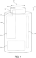
FIG. 1 is a perspective view, not to scale, of a handheld fluid ejection device containing a revolving maintenance station according to an embodiment of the disclosure. -
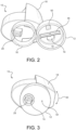
FIG. 2 is a perspective view from an ejection head end of the handheld fluid ejection device ofFIG. 1 with the revolving maintenance station removed. -
FIG. 3 is a perspective view from an ejection head end of the handheld fluid ejection device ofFIG. 2 with the revolving maintenance station oriented in a fluid ejection orientation. -
FIG. 4 is a perspective view from an ejection head end of the handheld fluid ejection device ofFIG. 2 with the revolving maintenance station oriented in an ejection head capping orientation. -
FIG. 5 is a perspective view of a portion of the handheld fluid ejection device ofFIG. 1 with the revolving maintenance station removed. -
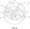
FIG. 6 is an inside perspective view of a revolving maintenance station for the handheld fluid ejection device ofFIG. 1 . -
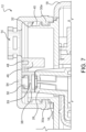
FIG. 7 is a cross-sectional view of the revolving maintenance station and fluid ejection device ofFIG. 1 with the revolving maintenance station in an extended position relative to an ejection head capping device. -
FIG. 8 is a cross-sectional view of the revolving maintenance station and fluid ejection device ofFIG. 7 with the revolving maintenance station in a retracted position relative to the ejection head capping device. -
FIG. 9 is a cross-sectional view of the revolving maintenance station and fluid ejection device ofFIG. 1 with the revolving maintenance station in an extended position relative to a fluid ejection port. -
FIG. 10 is a cross-sectional view of the revolving maintenance station and fluid ejection device ofFIG. 1 with the revolving maintenance station in a retracted position relative to the fluid ejection port. -
FIG. 11 is a cross-sectional view of the revolving maintenance station and fluid ejection device ofFIG. 1 with the revolving maintenance station in an extended position for wiping a fluid jet ejection head. -
FIGs. 12 and 13 are inside perspective views of revolving maintenance stations for the handheld fluid ejection device ofFIG. 1 according to other embodiments of the disclosure. -
FIGs. 14-16 are cross-sectional views of a revolving maintenance station and fluid ejection device according to another embodiment of the disclosure. -
FIG. 17 is an inside perspective view of a revolving maintenance station containing magnets for alignment according to another embodiment of the disclosure. -
FIG. 18 is a perspective view of the revolving maintenance station ofFIG. 17 attached to a housing of a fluid ejection device. -
FIG. 19 is a cross-sectional view of a revolving maintenance station and fluid ejection device according to another embodiment of the disclosure. -
FIG. 20 is a schematic view of an automated revolving maintenance station according to another embodiment of the disclosure. - With reference to
FIGs. 1-4 , there is provide a handheldfluid ejection device 10 that includes a revolvingmaintenance station 12. As described in more detail below, the maintenance station includes a wiper, an ejection head capping structure, and afluid ejection port 14. Themaintenance station 12 is rotatable about acircular wall 16 attached to thehousing 18 in the direction ofarrow 20 to provide wiping, ejection head capping and fluid ejection functions. - Handheld
fluid ejection devices 10 are used for a variety of applications including, but not limited to, printing, lubrication, pharmaceutical delivery, vapor devices and the like. The fluid ejection devices are typically self-contained devices that include thehousing 18, afluid reservoir 22, acontrol circuit board 24, and apower supply 26. -
FIG. 2 is an end perspective view of thefluid ejection device 10 with a molding for the revolvingmaintenance station 12 removed thereby exposing afluid ejection head 28. InFIG. 3 , the revolvingmaintenance station 12 is rotated to a fluid ejection orientation, thefluid ejection head 28 is adjacent to thefluid ejection port 14.FIG. 4 is an end perspective view of thefluid ejection device 10 wherein the revolvingmaintenance station 12 is rotated to an ejection head capping orientation. - The revolving
maintenance station 12 may be mated to thecircular wall 16 attached to thehousing 18 of the handheldfluid ejection device 10 in a variety of ways. A first embodiment is shown inFigures 5-11 , where the revolvingmaintenance station 12 includes tabs 30 (FIG. 6 ) extruded on aninner wall 32 thereof which can be fitted intogrooves 34 on theouter wall 36 of thecircular wall 16. It would be apparent to one skilled in the art that alternatively, tabs may be placed on theouter wall 36 of thehousing 18 and that the grooves may be provided on theinner wall 32 of the revolvingmaintenance station 12. Thegrooves 34 in theouter wall 36 of thehousing 18 enable for the revolvingmaintenance station 12 to rotate around the circumference of thecircular wall 16 and to be seated in the appropriate locations for either fluid ejection or for capping thefluid ejection head 28 with an ejectionhead capping device 38. The tabs 30 may includecircular tabs 30a andrectangular tabs 30b on the revolvingmaintenance station 12 that mate withparticular grooves 34 on theouter wall 36 of thehousing 18 so that either the ejectionhead capping device 38 or thefluid ejection port 14 is adjacent to thefluid ejection head 28. - In the embodiment illustrated in
FIG. 5 , arace 40 is provided in thecircular wall 16 for retaining the tabs 30 therein.Slots 42 in aretainer ring 44 enable the revolvingmaintenance station 12 to be removed from thecircular wall 16 for reconditioning components of the revolvingmaintenance station 12. A noteworthy feature of revolvingmaintenance station 12 is that themaintenance station 12 is readily replaceable so that thewiper blade 46 and capping device do not become excessively degraded. Either the entire maintenance station assembly can be replaced, or themaintenance station 12 may be designed so that only thewiper blade 46 andcapping device 38 are replaceable while maintaining the main body of themaintenance station 12.Interchangeable wiper blades 46 andcapping devices 38 provide an economical and environmental benefit for both the user and manufacturer. Accordingly, thewiper blade 46 may be removably attached to awiper blade holder 48 and the ejectionhead capping device 38 may be removably attached to acapping device holder 50 by a user so that the capping and wiping operations may be maintained throughout the life of the handheld fluidjet ejection device 10. - Each of the
wiper blade 46 and ejectionhead capping device 38 may be made of a resilient elastomeric material that provides suitable wiping and sealing characteristics. In some embodiments, thewiper blade 46 andcapping device 38 are made of a natural or synthetic rubber. Accordingly, thewiper blade 46 is positioned so that, when themaintenance station 12 is in the operating position, rotating themaintenance station 12 results in engagement of thewiper blade 46 with the face of thefluid ejection head 28 thereby removing debris or excess fluid before thefluid ejection head 28 is capped. In a first embodiment, thewiper blade 46 is positioned so that rotating the station in either direction provides the cleaning action desired before capping. - In some embodiments, a unidirectional rather than a bi-directional wiping motion is provided. Unidirectional wiping prevents the chance that a return wipe across the
ejection head 28 could result in recontamination of theejection head 28 with debris from thewiper blade 46. Accordingly, a ratchet-like mechanism may be provided to ensure that themaintenance station 12 is only rotated in a single direction so that the wiping is unidirectional. The single direction of rotation allows for the size of thewiper blade 46 to be reduced and placed on only a single side of themaintenance station 12 between thefluid ejection port 14 and thecapping device 38 as shown inFIG. 12 . - In another embodiment, a
wiper 52 made of an absorbent material may be placed opposite of thewiper blade 46 as shown inFIG. 13 . Theabsorbent wiper 52 may engage the face of theejection head 28 prior to aligning thefluid ejection port 14 with theejection head 28 and prior to operating the device. The absorbent properties of theabsorbent wiper 52 may be used to prime theejection head 28 by providing a wicking action with respect to the fluid to be ejected. Accordingly, theabsorbent wiper 52 may be made in various sizes to increase the duration of contact with theejection head 28. Anabsorbent wiper 52, as described above, would be impractical to implement in a conventional maintenance station, where an absorbent blade could only appear in series with the wiping blade. - In some embodiments, ejection
head capping device 38 may seal directly onto a face offluid ejection head 28 or may encompass an entirety offluid ejection head 28. Accordingly, the ejectionhead capping device 38 is meant to provide protection for thefluid ejection head 28 and to maintain a locally humid environment to prevent evaporation of the jetting fluid from nozzles offluid ejection head 28. The ejectionhead capping device 38 may also feature avent hole 55 therein to relieve pressure on thefluid ejection head 28 when seating thecapping device 38 into a resting position overfluid ejection head 28. Avent 54 communicated with outside may be formed on a top surface of themaintenance station 12. Thevent 54, as shown inFIG. 7 , may also provide an airflow path with thevent hole 55 of the ejectionhead capping device 38 from an outside ambient atmosphere into thefluid ejection head 28 so that when a fluid is jetted a vacuum does not form inside the revolvingmaintenance station 12. Typically,such vent 54 is sufficiently small so that the humidity inside the cappingdevice 38 remains relatively high. - In some embodiments, indicia 56 (
FIG. 5 ) may be provided on thehousing 18 to indicate the position of the revolvingmaintenance station 12. For a station which is manually rotated by the user, indicator marks located on thehousing 18 andcorresponding indicia 56 located on an outer wall of themaintenance station 12 may help the user identify the correct rotational positioning of themaintenance station 12 with respect to theejection head 28. Other means of indicating the correct position such as multi-colored or flashing lights, or audible cues may be used alone or in combination to alert a user of the correct positioning of themaintenance station 12. Errors in positioning of themaintenance station 12 may also be indicated by any of the foregoing indicia, lights or sounds. - As shown in
FIGs. 7-11 , the revolvingmaintenance station 12 may be operated to an extended position (FIG. 7 ) and retracted into a resting position (FIG. 8 ) with the ejectionhead capping device 38 adjacent to thefluid ejection head 28. The revolving maintenance station may also be extended (FIG. 9 ) and rotated into an operating position (FIG. 10 ) with thefluid ejection port 14 adjacent to thefluid ejection head 28. After ejecting fluid from thefluid ejection head 28, the revolving maintenance station may again be extended (FIG. 9 ) and rotated back to the resting position (FIG. 8 ) while thewiper blade 46 sweeps across thefluid ejection head 28 as shown inFIG. 11 . In some embodiments the foregoing revolving maintenance station may be manually extended, rotated, and retracted by a user. - As described above, the revolving
maintenance station 12 may be extended and retracted in a direction perpendicular to a face of thefluid ejection head 28. In some embodiments, the revolvingmaintenance station 12 is designed so that it must be extended before rotation, or the revolvingmaintenance station 12 may be designed so that rotation drives the extension of the revolvingmaintenance station 12 such as by providing V-shaped grooves and V-shaped tabs. - In some embodiments, illustrated in
FIGs. 14-17 , acentral shaft 58, having a first end mounted to thehousing 18 and a second end that extends beyond thecircular wall 16 may be provided. The first end of thecentral shaft 58 may be affixed to astopper 60 and the second end of the central shaft may be mated to a hole orboss 62 located at the center of the revolvingmaintenance station 64. Upper and lower limits for the stopper are provided to enable vertical travel of the revolvingmaintenance station 64 so that the revolvingmaintenance station 64 may be extended (FIG. 14 ) and retracted into a resting position (FIG. 15 ) with the ejectionhead capping device 38 adjacent to thefluid ejection head 28. As shown inFIG. 16 , the revolvingmaintenance station 64 may be extended and rotated while thewiper blade 46 sweeps across thefluid ejection head 28. In some embodiments the foregoing revolving maintenance station may be manually extended, rotated, and retracted by a user. -
FIG. 17 is an inside perspective view of the revolvingmaintenance station 64 andcentral shaft 58. One or more embeddedmagnets 66 may be provided on acircumferential edge 68 of themaintenance station 64 to aid in aligning themaintenance station 64 with thehousing 70 of the fluid ejection device. Accordingly, thehousing 70 may includemagnets 72 or metal inserts as shown inFIG. 18 to maintain proper positioning and alignment of the revolvingmaintenance station 64. When the embeddedmagnets maintenance station 64 with thehousing 74, there is no need for thecircular wall 16 or grooves 34 (FIG. 5 ) to provide alignment of the revolvingmaintenance station 64 with thehousing 74. Accordingly, thehousing 74 may be provided as shown inFIG. 19 without thecircular wall 16. - In some embodiments, the
central shaft 76 is attached to a stepper motor 78 (FIG. 20 ) rather than floating inside thehousing 70 for use in repositioning the revolvingmaintenance station 64. Thestepper motor 78 enables radial motion of the revolvingmaintenance station 64. Thestepper motor 78 may also be mounted to alinear actuator 80 to provide motion of the revolvingmaintenance station 64 in a direction coaxial to thecentral shaft 76 to enable the revolvingmaintenance station 64 to be lifted before rotating to its next position and then reseated. Thelinear actuator 80 is provided with enough torque to overcome the resistance of themagnets maintenance station 64 in a resting position. - The
linear actuator 80 andstepper motor 78 may also be designed to hold the position of the revolvingmaintenance station 64 until activated by a user or could be used in conjunction with the tabs 30 andgroove 34 ormagnets maintenance station 64. It is conceivable that thelinear actuator 80 may be programmed to apply a downward force while thewiper blade 46 is moving across the face of thefluid ejection head 28 to ensure engagement between thefluid ejection head 28 and thewiper blade 46. It is further conceivable that thelinear actuator 80 may be paired with a force sensor so that a predetermined amount of force can be applied to thefluid ejection head 28 by thewiper blade 46 to help alleviate any error in manufacturing tolerances or degradation of thewiper blade 46 over time. In some embodiments, the automatic maintenance station may be programmed to only rotate in a single direction. - Although the revolving maintenance station and its compact design are primarily aimed towards handheld fluid ejection devices, it is also conceivable that the revolving maintenance station described herein could be used in larger, stationary fluid ejection devices. Such a maintenance station would likely not require a fluid ejection port, as these devices typically translate the fluid ejection head to a desired fluid ejection location. Once an ejection head reaches its home position, a revolving maintenance station may be used to wipe and cap the ejection head using the actuating and rotating mechanisms as described above for the automatic maintenance station for a handheld fluid ejection device. While it is conceivable that the maintenance station may exist without a fluid ejection port for larger, stationary fluid ejection devices, for the handheld fluid ejection device it is convenient and compact to include a fluid ejection port through which fluid can be dispensed. The fluid ejection port may also feature various means by which to attach various diffusers and adapters to modify the behavior and flow of the jetted fluid. Such means may include clips, press fits, snap fits, threading, or magnets.
- Accordingly, the disclosed embodiments provide an apparatus and method for using a revolving maintenance station to wipe and cap the fluid ejection head. The handheld fluid ejection device includes only a few components: the revolving maintenance station, a fluid ejection head, a housing, a fluid reservoir, a circuit board and a power supply. The fluid ejection head and fluid reservoir are housed in the body of the housing all with all the electrical components necessary to operate the fluid ejection head.
- Although the embodiment shown in the figures demonstrates a round maintenance station, it is appreciated that one skilled in the art could envision similar devices featuring a maintenance station using various shapes or sizes. The unique characteristic of the disclosed embodiments pertains to the revolving nature of the mechanism, which allows for a compact arrangement of the components necessary for fluid ejection head maintenance. As set forth above, the mechanism may be manually or automatically actuated by the user and contains readily replaceable and maintainable components. Unlike conventional servicing stations, the revolving maintenance station features a built-in fluid ejection port so that the ejection head does not need to be translated to a separate position before dispensing a fluid.
- The currently disclosed apparatus acts as both the maintenance station and a storage housing for the fluid ejection head. As the maintenance station is rotated, multiple maintenance steps may be placed in series around the inside wall of the maintenance station to aid in both priming and cleaning the fluid ejection head.
- While particular embodiments have been described, alternatives, modifications, variations, improvements, and substantial equivalents that are or can be presently unforeseen can arise to applicants or others skilled in the art. Accordingly, the appended claims as filed and as they can be amended are intended to embrace all such alternatives, modifications variations, improvements, and substantial equivalents.
Claims (19)
- A fluid ejection device (10) comprising:a housing (18), a fluid reservoir (22) disposed in the housing (18) and a fluid ejection head (28); anda revolving maintenance station (12) comprising an ejection head wiper (46) and an ejection head capping device (38), wherein the revolving maintenance station (12) is movably attached to the housing (18) and is configured for rotation to selectively position the ejection head wiper (46) or the ejection head capping device (38) adjacent to the fluid ejection head (28).
- The fluid ejection device (10) of claim 1, wherein the ejection head capping device (38) is configured to protect the fluid ejection head (28) and to maintain an environment adjacent to the fluid ejection head (28) that prevents fluid from evaporating therefrom.
- The fluid ejection device (10) of claim 1, wherein the ejection head capping device (38) comprises a vent hole (55) therein.
- The fluid ejection device (10) of claim 1, wherein the revolving maintenance station (12) further comprises at least one tab (30) on an inside wall (32) thereof.
- The fluid ejection device (10) of claim 4, wherein the housing (18) further comprises a circular wall (16) having at least one groove (34) on an outside portion (36) thereof for mating with the at least one tab (30) of the revolving maintenance station (12).
- The fluid ejection device of claim 1, wherein the revolving maintenance station (12) is configured to be manually rotated relative to the housing (18).
- The fluid ejection device (10) of claim 1, wherein the revolving maintenance station (12) is configured to be automatically rotated relative to the housing (18).
- The fluid ejection device (10) of claim 1, wherein the ejection head wiper (46) comprises an elastomeric wiper blade (46).
- The fluid ejection device (10) of claim 1, wherein the ejection head capping devices (38) comprises an elastomeric capping device.
- The fluid ejection device (10) of claim 1, wherein the revolving maintenance station (12) further comprises an absorbent wiper blade (52).
- The fluid ejection device (10) of claim 1, wherein the revolving maintenance station (12) further comprises a fluid ejection port (14) therein.
- The fluid ejection device (10) of claim 1, further comprising a central shaft (58) configured to movably attach the revolving maintenance station (12) to the housing (18).
- A handheld fluid ejection device (10) comprising:a housing (18), a fluid reservoir (22) disposed in the housing (18) and a fluid ejection head (28); anda revolving maintenance station (12) comprising an ejection head wiper (46), an ejection head capping device (38), and a fluid ejection port (14) therein, wherein the revolving maintenance station (12) is movably attached to the housing (18) and is configured for rotation to selectively position the ejection head wiper (46), the ejection head capping device (38), or the fluid ejection port (14) adjacent to the fluid ejection head (28).
- The handheld fluid ejection device (10) of claim 13, wherein the revolving maintenance station (12) is configured to be manually rotated relative to the housing (18).
- The handheld fluid ejection device (10) of claim 13, wherein the revolving maintenance station (12) further comprises at least one V-shaped tab on an inside wall (32) thereof.
- The handheld fluid ejection device (10) of claim 15, wherein the housing (18) further comprises a circular wall (16) having at least one V-shaped groove on an outside portion (36) thereof for mating with the at least one V-shaped tab of the revolving maintenance station (12).
- The handheld fluid ejection device (10) of claim 16, wherein the revolving maintenance station (12) is biased toward the housing (18).
- The handheld fluid ejection device (10) of claim 13, further comprising a central shaft (58) attached to the housing (18), wherein the revolving maintenance station (12) is movably attached to the central shaft (58).
- The handheld fluid ejection device (10) of claim 13, further comprising magnets (72) disposed on the housing (70), on the revolving maintenance station (12), or on the housing (70) and the revolving maintenance station (64) configured to selectively position the revolving maintenance station (64).
Applications Claiming Priority (1)
| Application Number | Priority Date | Filing Date | Title |
|---|---|---|---|
| US17/805,499 US11931758B2 (en) | 2022-06-06 | 2022-06-06 | Revolving maintenance station for fluid ejection device |
Publications (1)
| Publication Number | Publication Date |
|---|---|
| EP4289627A1 true EP4289627A1 (en) | 2023-12-13 |
Family
ID=86469408
Family Applications (1)
| Application Number | Title | Priority Date | Filing Date |
|---|---|---|---|
| EP23174236.2A Pending EP4289627A1 (en) | 2022-06-06 | 2023-05-19 | Fluid ejection device and handheld fluid ejection device |
Country Status (4)
| Country | Link |
|---|---|
| US (1) | US11931758B2 (en) |
| EP (1) | EP4289627A1 (en) |
| JP (1) | JP2023178961A (en) |
| CN (1) | CN117183579A (en) |
Citations (2)
| Publication number | Priority date | Publication date | Assignee | Title |
|---|---|---|---|---|
| JPH1016316A (en) * | 1996-06-27 | 1998-01-20 | Brother Ind Ltd | Printing device |
| US20210323328A1 (en) * | 2015-12-07 | 2021-10-21 | The Procter & Gamble Company | Systems and methods for providing a service station routine |
Family Cites Families (6)
| Publication number | Priority date | Publication date | Assignee | Title |
|---|---|---|---|---|
| MXPA02004128A (en) | 1999-10-25 | 2004-04-02 | Silverbrook Res Pty Ltd | ELECTRONICALLY CONTROLLABLE FEATHER. |
| US7997683B2 (en) | 2007-03-02 | 2011-08-16 | Marvell International Ltd. | Device for servicing an inkjet print head on a hand held printer |
| US9782971B2 (en) * | 2015-12-07 | 2017-10-10 | The Procter & Gamble Company | Cartridge servicing cases for fluid jet cartridge |
| US9616668B1 (en) | 2015-12-07 | 2017-04-11 | The Procter & Gamble Company | Servicing cassettes for handheld fluid jet apparatuses for use in modifying surfaces |
| US10512921B2 (en) | 2016-05-09 | 2019-12-24 | Funai Electric Co., Ltd. | Maintenance apparatus for vaporizing device |
| US10934079B2 (en) * | 2019-03-12 | 2021-03-02 | Derek S. Jancisin | Cleaning mechanism for spray and aerosol nozzles |
-
2022
- 2022-06-06 US US17/805,499 patent/US11931758B2/en active Active
-
2023
- 2023-05-19 EP EP23174236.2A patent/EP4289627A1/en active Pending
- 2023-05-30 JP JP2023088721A patent/JP2023178961A/en active Pending
- 2023-05-31 CN CN202310631834.1A patent/CN117183579A/en active Pending
Patent Citations (2)
| Publication number | Priority date | Publication date | Assignee | Title |
|---|---|---|---|---|
| JPH1016316A (en) * | 1996-06-27 | 1998-01-20 | Brother Ind Ltd | Printing device |
| US20210323328A1 (en) * | 2015-12-07 | 2021-10-21 | The Procter & Gamble Company | Systems and methods for providing a service station routine |
Also Published As
| Publication number | Publication date |
|---|---|
| JP2023178961A (en) | 2023-12-18 |
| US11931758B2 (en) | 2024-03-19 |
| CN117183579A (en) | 2023-12-08 |
| US20230390797A1 (en) | 2023-12-07 |
Similar Documents
| Publication | Publication Date | Title |
|---|---|---|
| US7798599B2 (en) | Fluid-ejection device service station | |
| US8454120B2 (en) | Liquid ejection device | |
| US7824003B2 (en) | Fluid-ejection device service station | |
| US9168754B2 (en) | Liquid ejection apparatus | |
| EP0576033B1 (en) | Ink-jet recording device | |
| CN108501534B (en) | Liquid ejection head unit, liquid ejection device and maintenance method thereof | |
| US20110090282A1 (en) | Head repairing apparatus and fluid ejecting apparatus | |
| JP2009096034A (en) | Fluid ejection device | |
| EP1065060B1 (en) | A method and apparatus for filling and capping an acoustic ink printhead | |
| US8235498B2 (en) | Head repairing apparatus and fluid ejecting apparatus | |
| JP5365803B2 (en) | HEAD MAINTENANCE DEVICE AND LIQUID EJECTING DEVICE HAVING THE HEAD MAINTENANCE DEVICE | |
| US11931758B2 (en) | Revolving maintenance station for fluid ejection device | |
| US8388100B2 (en) | Head repairing apparatus and fluid ejecting apparatus | |
| US6817695B1 (en) | Printhead capping assembly | |
| US6517187B1 (en) | Method and apparatus for cleaning residual ink from printhead nozzle faces | |
| US6755503B2 (en) | Housekeeping station | |
| JP2012144003A (en) | Liquid ejection apparatus | |
| US20090295863A1 (en) | Continuous inkjet printhead nozzle cap | |
| JP3138655B2 (en) | Cap mechanism of inkjet recording device | |
| JP3589238B2 (en) | Liquid injection device | |
| JP2002316421A (en) | Ink jet recording device | |
| JP2516901B2 (en) | Liquid ejection device recovery method | |
| JPH11300980A (en) | Ink jet recording device | |
| KR20010005322A (en) | Inkjet printer | |
| JPH08174854A (en) | Cap device for inkjet recording device |
Legal Events
| Date | Code | Title | Description |
|---|---|---|---|
| PUAI | Public reference made under article 153(3) epc to a published international application that has entered the european phase |
Free format text: ORIGINAL CODE: 0009012 |
|
| STAA | Information on the status of an ep patent application or granted ep patent |
Free format text: STATUS: THE APPLICATION HAS BEEN PUBLISHED |
|
| AK | Designated contracting states |
Kind code of ref document: A1 Designated state(s): AL AT BE BG CH CY CZ DE DK EE ES FI FR GB GR HR HU IE IS IT LI LT LU LV MC ME MK MT NL NO PL PT RO RS SE SI SK SM TR |
|
| STAA | Information on the status of an ep patent application or granted ep patent |
Free format text: STATUS: REQUEST FOR EXAMINATION WAS MADE |
|
| 17P | Request for examination filed |
Effective date: 20240124 |
|
| RBV | Designated contracting states (corrected) |
Designated state(s): AL AT BE BG CH CY CZ DE DK EE ES FI FR GB GR HR HU IE IS IT LI LT LU LV MC ME MK MT NL NO PL PT RO RS SE SI SK SM TR |
|
| GRAP | Despatch of communication of intention to grant a patent |
Free format text: ORIGINAL CODE: EPIDOSNIGR1 |
|
| STAA | Information on the status of an ep patent application or granted ep patent |
Free format text: STATUS: GRANT OF PATENT IS INTENDED |
|
| INTG | Intention to grant announced |
Effective date: 20241111 |
|
| 19U | Interruption of proceedings before grant |
Effective date: 20241024 |