EP4289605A1 - Polymeric component and method of making the same - Google Patents
Polymeric component and method of making the same Download PDFInfo
- Publication number
- EP4289605A1 EP4289605A1 EP23177205.4A EP23177205A EP4289605A1 EP 4289605 A1 EP4289605 A1 EP 4289605A1 EP 23177205 A EP23177205 A EP 23177205A EP 4289605 A1 EP4289605 A1 EP 4289605A1
- Authority
- EP
- European Patent Office
- Prior art keywords
- thermoset
- thermal barrier
- thermoplastic
- component
- interlayer
- Prior art date
- Legal status (The legal status is an assumption and is not a legal conclusion. Google has not performed a legal analysis and makes no representation as to the accuracy of the status listed.)
- Granted
Links
Images

Classifications
-
- B—PERFORMING OPERATIONS; TRANSPORTING
- B29—WORKING OF PLASTICS; WORKING OF SUBSTANCES IN A PLASTIC STATE IN GENERAL
- B29C—SHAPING OR JOINING OF PLASTICS; SHAPING OF MATERIAL IN A PLASTIC STATE, NOT OTHERWISE PROVIDED FOR; AFTER-TREATMENT OF THE SHAPED PRODUCTS, e.g. REPAIRING
- B29C66/00—General aspects of processes or apparatus for joining preformed parts
- B29C66/70—General aspects of processes or apparatus for joining preformed parts characterised by the composition, physical properties or the structure of the material of the parts to be joined; Joining with non-plastics material
- B29C66/72—General aspects of processes or apparatus for joining preformed parts characterised by the composition, physical properties or the structure of the material of the parts to be joined; Joining with non-plastics material characterised by the structure of the material of the parts to be joined
- B29C66/721—Fibre-reinforced materials
-
- B—PERFORMING OPERATIONS; TRANSPORTING
- B23—MACHINE TOOLS; METAL-WORKING NOT OTHERWISE PROVIDED FOR
- B23K—SOLDERING OR UNSOLDERING; WELDING; CLADDING OR PLATING BY SOLDERING OR WELDING; CUTTING BY APPLYING HEAT LOCALLY, e.g. FLAME CUTTING; WORKING BY LASER BEAM
- B23K35/00—Rods, electrodes, materials, or media, for use in soldering, welding, or cutting
- B23K35/22—Rods, electrodes, materials, or media, for use in soldering, welding, or cutting characterised by the composition or nature of the material
- B23K35/36—Selection of non-metallic compositions, e.g. coatings or fluxes; Selection of soldering or welding materials, conjoint with selection of non-metallic compositions, both selections being of interest
- B23K35/3601—Selection of non-metallic compositions, e.g. coatings or fluxes; Selection of soldering or welding materials, conjoint with selection of non-metallic compositions, both selections being of interest with inorganic compounds as principal constituents
-
- B—PERFORMING OPERATIONS; TRANSPORTING
- B23—MACHINE TOOLS; METAL-WORKING NOT OTHERWISE PROVIDED FOR
- B23K—SOLDERING OR UNSOLDERING; WELDING; CLADDING OR PLATING BY SOLDERING OR WELDING; CUTTING BY APPLYING HEAT LOCALLY, e.g. FLAME CUTTING; WORKING BY LASER BEAM
- B23K35/00—Rods, electrodes, materials, or media, for use in soldering, welding, or cutting
- B23K35/22—Rods, electrodes, materials, or media, for use in soldering, welding, or cutting characterised by the composition or nature of the material
- B23K35/36—Selection of non-metallic compositions, e.g. coatings or fluxes; Selection of soldering or welding materials, conjoint with selection of non-metallic compositions, both selections being of interest
- B23K35/3612—Selection of non-metallic compositions, e.g. coatings or fluxes; Selection of soldering or welding materials, conjoint with selection of non-metallic compositions, both selections being of interest with organic compounds as principal constituents
-
- B—PERFORMING OPERATIONS; TRANSPORTING
- B29—WORKING OF PLASTICS; WORKING OF SUBSTANCES IN A PLASTIC STATE IN GENERAL
- B29C—SHAPING OR JOINING OF PLASTICS; SHAPING OF MATERIAL IN A PLASTIC STATE, NOT OTHERWISE PROVIDED FOR; AFTER-TREATMENT OF THE SHAPED PRODUCTS, e.g. REPAIRING
- B29C65/00—Joining or sealing of preformed parts, e.g. welding of plastics materials; Apparatus therefor
- B29C65/02—Joining or sealing of preformed parts, e.g. welding of plastics materials; Apparatus therefor by heating, with or without pressure
-
- B—PERFORMING OPERATIONS; TRANSPORTING
- B29—WORKING OF PLASTICS; WORKING OF SUBSTANCES IN A PLASTIC STATE IN GENERAL
- B29C—SHAPING OR JOINING OF PLASTICS; SHAPING OF MATERIAL IN A PLASTIC STATE, NOT OTHERWISE PROVIDED FOR; AFTER-TREATMENT OF THE SHAPED PRODUCTS, e.g. REPAIRING
- B29C65/00—Joining or sealing of preformed parts, e.g. welding of plastics materials; Apparatus therefor
- B29C65/48—Joining or sealing of preformed parts, e.g. welding of plastics materials; Apparatus therefor using adhesives, i.e. using supplementary joining material; solvent bonding
- B29C65/4805—Joining or sealing of preformed parts, e.g. welding of plastics materials; Apparatus therefor using adhesives, i.e. using supplementary joining material; solvent bonding characterised by the type of adhesives
- B29C65/481—Non-reactive adhesives, e.g. physically hardening adhesives
- B29C65/4815—Hot melt adhesives, e.g. thermoplastic adhesives
-
- B—PERFORMING OPERATIONS; TRANSPORTING
- B29—WORKING OF PLASTICS; WORKING OF SUBSTANCES IN A PLASTIC STATE IN GENERAL
- B29C—SHAPING OR JOINING OF PLASTICS; SHAPING OF MATERIAL IN A PLASTIC STATE, NOT OTHERWISE PROVIDED FOR; AFTER-TREATMENT OF THE SHAPED PRODUCTS, e.g. REPAIRING
- B29C65/00—Joining or sealing of preformed parts, e.g. welding of plastics materials; Apparatus therefor
- B29C65/48—Joining or sealing of preformed parts, e.g. welding of plastics materials; Apparatus therefor using adhesives, i.e. using supplementary joining material; solvent bonding
- B29C65/50—Joining or sealing of preformed parts, e.g. welding of plastics materials; Apparatus therefor using adhesives, i.e. using supplementary joining material; solvent bonding using adhesive tape, e.g. thermoplastic tape; using threads or the like
- B29C65/5057—Joining or sealing of preformed parts, e.g. welding of plastics materials; Apparatus therefor using adhesives, i.e. using supplementary joining material; solvent bonding using adhesive tape, e.g. thermoplastic tape; using threads or the like positioned between the surfaces to be joined
-
- B—PERFORMING OPERATIONS; TRANSPORTING
- B29—WORKING OF PLASTICS; WORKING OF SUBSTANCES IN A PLASTIC STATE IN GENERAL
- B29C—SHAPING OR JOINING OF PLASTICS; SHAPING OF MATERIAL IN A PLASTIC STATE, NOT OTHERWISE PROVIDED FOR; AFTER-TREATMENT OF THE SHAPED PRODUCTS, e.g. REPAIRING
- B29C66/00—General aspects of processes or apparatus for joining preformed parts
- B29C66/01—General aspects dealing with the joint area or with the area to be joined
- B29C66/05—Particular design of joint configurations
- B29C66/10—Particular design of joint configurations particular design of the joint cross-sections
- B29C66/11—Joint cross-sections comprising a single joint-segment, i.e. one of the parts to be joined comprising a single joint-segment in the joint cross-section
- B29C66/112—Single lapped joints
- B29C66/1122—Single lap to lap joints, i.e. overlap joints
-
- B—PERFORMING OPERATIONS; TRANSPORTING
- B29—WORKING OF PLASTICS; WORKING OF SUBSTANCES IN A PLASTIC STATE IN GENERAL
- B29C—SHAPING OR JOINING OF PLASTICS; SHAPING OF MATERIAL IN A PLASTIC STATE, NOT OTHERWISE PROVIDED FOR; AFTER-TREATMENT OF THE SHAPED PRODUCTS, e.g. REPAIRING
- B29C66/00—General aspects of processes or apparatus for joining preformed parts
- B29C66/40—General aspects of joining substantially flat articles, e.g. plates, sheets or web-like materials; Making flat seams in tubular or hollow articles; Joining single elements to substantially flat surfaces
- B29C66/41—Joining substantially flat articles ; Making flat seams in tubular or hollow articles
- B29C66/45—Joining of substantially the whole surface of the articles
-
- B—PERFORMING OPERATIONS; TRANSPORTING
- B29—WORKING OF PLASTICS; WORKING OF SUBSTANCES IN A PLASTIC STATE IN GENERAL
- B29C—SHAPING OR JOINING OF PLASTICS; SHAPING OF MATERIAL IN A PLASTIC STATE, NOT OTHERWISE PROVIDED FOR; AFTER-TREATMENT OF THE SHAPED PRODUCTS, e.g. REPAIRING
- B29C66/00—General aspects of processes or apparatus for joining preformed parts
- B29C66/70—General aspects of processes or apparatus for joining preformed parts characterised by the composition, physical properties or the structure of the material of the parts to be joined; Joining with non-plastics material
- B29C66/72—General aspects of processes or apparatus for joining preformed parts characterised by the composition, physical properties or the structure of the material of the parts to be joined; Joining with non-plastics material characterised by the structure of the material of the parts to be joined
- B29C66/723—General aspects of processes or apparatus for joining preformed parts characterised by the composition, physical properties or the structure of the material of the parts to be joined; Joining with non-plastics material characterised by the structure of the material of the parts to be joined being multi-layered
-
- B—PERFORMING OPERATIONS; TRANSPORTING
- B29—WORKING OF PLASTICS; WORKING OF SUBSTANCES IN A PLASTIC STATE IN GENERAL
- B29C—SHAPING OR JOINING OF PLASTICS; SHAPING OF MATERIAL IN A PLASTIC STATE, NOT OTHERWISE PROVIDED FOR; AFTER-TREATMENT OF THE SHAPED PRODUCTS, e.g. REPAIRING
- B29C66/00—General aspects of processes or apparatus for joining preformed parts
- B29C66/70—General aspects of processes or apparatus for joining preformed parts characterised by the composition, physical properties or the structure of the material of the parts to be joined; Joining with non-plastics material
- B29C66/72—General aspects of processes or apparatus for joining preformed parts characterised by the composition, physical properties or the structure of the material of the parts to be joined; Joining with non-plastics material characterised by the structure of the material of the parts to be joined
- B29C66/723—General aspects of processes or apparatus for joining preformed parts characterised by the composition, physical properties or the structure of the material of the parts to be joined; Joining with non-plastics material characterised by the structure of the material of the parts to be joined being multi-layered
- B29C66/7234—General aspects of processes or apparatus for joining preformed parts characterised by the composition, physical properties or the structure of the material of the parts to be joined; Joining with non-plastics material characterised by the structure of the material of the parts to be joined being multi-layered comprising a barrier layer
-
- B—PERFORMING OPERATIONS; TRANSPORTING
- B29—WORKING OF PLASTICS; WORKING OF SUBSTANCES IN A PLASTIC STATE IN GENERAL
- B29C—SHAPING OR JOINING OF PLASTICS; SHAPING OF MATERIAL IN A PLASTIC STATE, NOT OTHERWISE PROVIDED FOR; AFTER-TREATMENT OF THE SHAPED PRODUCTS, e.g. REPAIRING
- B29C66/00—General aspects of processes or apparatus for joining preformed parts
- B29C66/70—General aspects of processes or apparatus for joining preformed parts characterised by the composition, physical properties or the structure of the material of the parts to be joined; Joining with non-plastics material
- B29C66/73—General aspects of processes or apparatus for joining preformed parts characterised by the composition, physical properties or the structure of the material of the parts to be joined; Joining with non-plastics material characterised by the intensive physical properties of the material of the parts to be joined, by the optical properties of the material of the parts to be joined, by the extensive physical properties of the parts to be joined, by the state of the material of the parts to be joined or by the material of the parts to be joined being a thermoplastic or a thermoset
- B29C66/731—General aspects of processes or apparatus for joining preformed parts characterised by the composition, physical properties or the structure of the material of the parts to be joined; Joining with non-plastics material characterised by the intensive physical properties of the material of the parts to be joined, by the optical properties of the material of the parts to be joined, by the extensive physical properties of the parts to be joined, by the state of the material of the parts to be joined or by the material of the parts to be joined being a thermoplastic or a thermoset characterised by the intensive physical properties of the material of the parts to be joined
- B29C66/7311—Thermal properties
-
- B—PERFORMING OPERATIONS; TRANSPORTING
- B29—WORKING OF PLASTICS; WORKING OF SUBSTANCES IN A PLASTIC STATE IN GENERAL
- B29C—SHAPING OR JOINING OF PLASTICS; SHAPING OF MATERIAL IN A PLASTIC STATE, NOT OTHERWISE PROVIDED FOR; AFTER-TREATMENT OF THE SHAPED PRODUCTS, e.g. REPAIRING
- B29C66/00—General aspects of processes or apparatus for joining preformed parts
- B29C66/70—General aspects of processes or apparatus for joining preformed parts characterised by the composition, physical properties or the structure of the material of the parts to be joined; Joining with non-plastics material
- B29C66/73—General aspects of processes or apparatus for joining preformed parts characterised by the composition, physical properties or the structure of the material of the parts to be joined; Joining with non-plastics material characterised by the intensive physical properties of the material of the parts to be joined, by the optical properties of the material of the parts to be joined, by the extensive physical properties of the parts to be joined, by the state of the material of the parts to be joined or by the material of the parts to be joined being a thermoplastic or a thermoset
- B29C66/739—General aspects of processes or apparatus for joining preformed parts characterised by the composition, physical properties or the structure of the material of the parts to be joined; Joining with non-plastics material characterised by the intensive physical properties of the material of the parts to be joined, by the optical properties of the material of the parts to be joined, by the extensive physical properties of the parts to be joined, by the state of the material of the parts to be joined or by the material of the parts to be joined being a thermoplastic or a thermoset characterised by the material of the parts to be joined being a thermoplastic or a thermoset
- B29C66/7392—General aspects of processes or apparatus for joining preformed parts characterised by the composition, physical properties or the structure of the material of the parts to be joined; Joining with non-plastics material characterised by the intensive physical properties of the material of the parts to be joined, by the optical properties of the material of the parts to be joined, by the extensive physical properties of the parts to be joined, by the state of the material of the parts to be joined or by the material of the parts to be joined being a thermoplastic or a thermoset characterised by the material of the parts to be joined being a thermoplastic or a thermoset characterised by the material of at least one of the parts being a thermoplastic
-
- B—PERFORMING OPERATIONS; TRANSPORTING
- B29—WORKING OF PLASTICS; WORKING OF SUBSTANCES IN A PLASTIC STATE IN GENERAL
- B29C—SHAPING OR JOINING OF PLASTICS; SHAPING OF MATERIAL IN A PLASTIC STATE, NOT OTHERWISE PROVIDED FOR; AFTER-TREATMENT OF THE SHAPED PRODUCTS, e.g. REPAIRING
- B29C66/00—General aspects of processes or apparatus for joining preformed parts
- B29C66/70—General aspects of processes or apparatus for joining preformed parts characterised by the composition, physical properties or the structure of the material of the parts to be joined; Joining with non-plastics material
- B29C66/73—General aspects of processes or apparatus for joining preformed parts characterised by the composition, physical properties or the structure of the material of the parts to be joined; Joining with non-plastics material characterised by the intensive physical properties of the material of the parts to be joined, by the optical properties of the material of the parts to be joined, by the extensive physical properties of the parts to be joined, by the state of the material of the parts to be joined or by the material of the parts to be joined being a thermoplastic or a thermoset
- B29C66/739—General aspects of processes or apparatus for joining preformed parts characterised by the composition, physical properties or the structure of the material of the parts to be joined; Joining with non-plastics material characterised by the intensive physical properties of the material of the parts to be joined, by the optical properties of the material of the parts to be joined, by the extensive physical properties of the parts to be joined, by the state of the material of the parts to be joined or by the material of the parts to be joined being a thermoplastic or a thermoset characterised by the material of the parts to be joined being a thermoplastic or a thermoset
- B29C66/7394—General aspects of processes or apparatus for joining preformed parts characterised by the composition, physical properties or the structure of the material of the parts to be joined; Joining with non-plastics material characterised by the intensive physical properties of the material of the parts to be joined, by the optical properties of the material of the parts to be joined, by the extensive physical properties of the parts to be joined, by the state of the material of the parts to be joined or by the material of the parts to be joined being a thermoplastic or a thermoset characterised by the material of the parts to be joined being a thermoplastic or a thermoset characterised by the material of at least one of the parts being a thermoset
-
- D—TEXTILES; PAPER
- D01—NATURAL OR MAN-MADE THREADS OR FIBRES; SPINNING
- D01F—CHEMICAL FEATURES IN THE MANUFACTURE OF ARTIFICIAL FILAMENTS, THREADS, FIBRES, BRISTLES OR RIBBONS; APPARATUS SPECIALLY ADAPTED FOR THE MANUFACTURE OF CARBON FILAMENTS
- D01F9/00—Artificial filaments or the like of other substances; Manufacture thereof; Apparatus specially adapted for the manufacture of carbon filaments
- D01F9/08—Artificial filaments or the like of other substances; Manufacture thereof; Apparatus specially adapted for the manufacture of carbon filaments of inorganic material
- D01F9/12—Carbon filaments; Apparatus specially adapted for the manufacture thereof
-
- B—PERFORMING OPERATIONS; TRANSPORTING
- B23—MACHINE TOOLS; METAL-WORKING NOT OTHERWISE PROVIDED FOR
- B23K—SOLDERING OR UNSOLDERING; WELDING; CLADDING OR PLATING BY SOLDERING OR WELDING; CUTTING BY APPLYING HEAT LOCALLY, e.g. FLAME CUTTING; WORKING BY LASER BEAM
- B23K2103/00—Materials to be soldered, welded or cut
- B23K2103/30—Organic materials
- B23K2103/38—Fabrics; Fibrous materials
-
- B—PERFORMING OPERATIONS; TRANSPORTING
- B29—WORKING OF PLASTICS; WORKING OF SUBSTANCES IN A PLASTIC STATE IN GENERAL
- B29C—SHAPING OR JOINING OF PLASTICS; SHAPING OF MATERIAL IN A PLASTIC STATE, NOT OTHERWISE PROVIDED FOR; AFTER-TREATMENT OF THE SHAPED PRODUCTS, e.g. REPAIRING
- B29C66/00—General aspects of processes or apparatus for joining preformed parts
- B29C66/70—General aspects of processes or apparatus for joining preformed parts characterised by the composition, physical properties or the structure of the material of the parts to be joined; Joining with non-plastics material
- B29C66/72—General aspects of processes or apparatus for joining preformed parts characterised by the composition, physical properties or the structure of the material of the parts to be joined; Joining with non-plastics material characterised by the structure of the material of the parts to be joined
- B29C66/721—Fibre-reinforced materials
- B29C66/7212—Fibre-reinforced materials characterised by the composition of the fibres
-
- B—PERFORMING OPERATIONS; TRANSPORTING
- B29—WORKING OF PLASTICS; WORKING OF SUBSTANCES IN A PLASTIC STATE IN GENERAL
- B29L—INDEXING SCHEME ASSOCIATED WITH SUBCLASS B29C, RELATING TO PARTICULAR ARTICLES
- B29L2031/00—Other particular articles
- B29L2031/30—Vehicles, e.g. ships or aircraft, or body parts thereof
- B29L2031/3076—Aircrafts
Definitions
- a gas turbine engine typically includes a fan section, a compressor section, a combustor section and a turbine section. Air entering the compressor section is compressed and delivered into the combustion section where it is mixed with fuel and ignited to generate a high-energy exhaust gas flow. The high-energy exhaust gas flow expands through the turbine section to drive the compressor and the fan section.
- the compressor section typically includes low and high pressure compressors, and the turbine section includes low and high pressure turbines.
- This disclosure relates to polymeric composite articles.
- Components such as gas turbine engine components, may have certain performance requirements yet may benefit from being lightweight.
- thermoset component for joining with a thermoplastic component includes a thermoset material, a weldable surface on the thermoset material, and a thermal barrier.
- the weldable surface includes a thermoplastic material.
- thermoplastic material of the weldable surface is an interlayer disposed on the thermal barrier.
- the thermal barrier is arranged between the interlayer and the thermoset material.
- the interlayer is a first interlayer.
- the thermoset component also includes a second interlayer between the thermal barrier and the thermoset material.
- thermoplastic material of the weldable surface is thermoplastic fibers within the thermal barrier.
- thermoplastic material of the weldable surface is infiltrated in the thermal barrier.
- the thermal barrier comprises ceramic or polymeric fibers.
- the thermal barrier comprises carbon fibers.
- the fibers are woven.
- the fibers are nonwoven.
- the thermal barrier comprises ceramic or polymeric fibers.
- the thermal barrier comprises carbon fibers.
- the thermal barrier is at the joint.
- the fibers are woven.
- the fibers are nonwoven.
- a method of making a hybrid polymeric component according to an exemplary embodiment of this disclosure includes forming a thermoset portion including a thermoset material and a weldable surface on the thermoset material, the weldable surface including a thermoplastic material, and a thermal barrier. The method also includes joining a thermoplastic portion to the thermoset portion by welding the thermoplastic portion to the weldable surface.
- the thermal barrier comprises ceramic or polymeric fibers.
- thermoplastic material of the weldable surface is thermoplastic fibers within the thermal barrier.
- the exemplary engine 20 generally includes a low speed spool 30 and a high speed spool 32 mounted for rotation about an engine central longitudinal axis A relative to an engine static structure 36 via several bearing systems 38. It should be understood that various bearing systems 38 at various locations may alternatively or additionally be provided, and the location of bearing systems 38 may be varied as appropriate to the application.
- the core airflow is compressed by the low pressure compressor 44 then the high pressure compressor 52, mixed and burned with fuel in the combustor 56, then expanded through the high pressure turbine 54 and low pressure turbine 46.
- the mid-turbine frame 57 includes airfoils 59 which are in the core airflow path C.
- the turbines 46, 54 rotationally drive the respective low speed spool 30 and high speed spool 32 in response to the expansion.
- gear system 48 may be located aft of the low pressure compressor, or aft of the combustor section 26 or even aft of turbine section 28, and fan 42 may be positioned forward or aft of the location of gear system 48.
- the engine 20 in one example is a high-bypass geared aircraft engine.
- the engine 20 bypass ratio is greater than about six (6), with an example embodiment being greater than about ten (10), and can be less than or equal to about 18.0, or more narrowly can be less than or equal to 16.0.
- the geared architecture 48 is an epicyclic gear train, such as a planetary gear system or other gear system, with a gear reduction ratio of greater than about 2.3.
- the gear reduction ratio may be less than or equal to 4.0.
- the low pressure turbine 46 has a pressure ratio that is greater than about five.
- the low pressure turbine pressure ratio can be less than or equal to 13.0, or more narrowly less than or equal to 12.0.
- the engine 20 bypass ratio is greater than about ten (10:1)
- the fan diameter is significantly larger than that of the low pressure compressor 44
- the low pressure turbine 46 has a pressure ratio that is greater than about five 5:1.
- Low pressure turbine 46 pressure ratio is pressure measured prior to an inlet of low pressure turbine 46 as related to the pressure at the outlet of the low pressure turbine 46 prior to an exhaust nozzle.
- the geared architecture 48 may be an epicycle gear train, such as a planetary gear system or other gear system, with a gear reduction ratio of greater than about 2.3:1 and less than about 5:1. It should be understood, however, that the above parameters are only exemplary of one embodiment of a geared architecture engine and that the present invention is applicable to other gas turbine engines including direct drive turbofans.
- thermoset and thermoplastic composites adds weight to components including these hybrid systems.
- Mechanical fasteners are therefore not desired for certain applications where lightweight components are preferred.
- Mechanical fastening methods may also pose challenges and lead to problems arising from drilling with generation of high-stress concentrated areas and/or fiber breakage, galvanic corrosion, mismatch of coefficient of thermal expansion between the composites and the fasteners, and labor intensiveness.
- the thermoplastic portion 104 can include polyetheretherketone (PEEK), polyetherimide (PEI), polyphenylene sulfide (PPS), polysulfone (PSU), polyethersulfone (PES), polyetherketoneketone (PEKK), polyaryletherketone (PAEK), or combinations thereof.
- the thermoset portion 102 can be an epoxy-based material, for instance.
- the interlayer 110 is selected to be chemically compatible with the material of the prepreg 108 and the thermal barrier 107 as well as the thermoplastic portion 104, and to be curable under similar conditions as the material of the prepreg 108.
- Chemical compatibility generally, is achieved when there are no or minimal undesirable chemical reactions between the material of the interlayer 110 and the prepreg 108/ thermal barrier 107 and can allow for interdiffusion between materials to promote adhesion.
- materials for the interlayer 110 are polyetheretherketone (PEEK), polyetherimide (PEI), polyphenylene sulfide (PPS), polysulfone (PSU), polyethersulfone (PES), polyetherketoneketone (PEKK), and polyaryletherketone (PAEK).
- PEEK polyetheretherketone
- PEI polyetherimide
- PPS polyphenylene sulfide
- PSU polysulfone
- PES polyethersulfone
- PEKK polyetherketoneketone
- the interlayer 110a/110b may also act as an adhesion promoting layer or additional thermal barrier layer, may promote bonding of the interlayer 110a/110b to the prepreg 108 and/or the thermal barrier 107 during co-cure, and/or may provide temperature bridging for joining the thermoplastic component 104 to the thermoset component 102 where the thermoplastic component 104 requires a significantly higher processing temperature compared to the thermoset component 102/interlayer 110/110a. Temperature bridging may improve the joint 106 quality if there exists a large difference in melt temperature between the dissimilar materials of the thermoplastic component 104 and thermoset component 102/interlayer 110/110a during joining in subsequent method steps discussed below. A polymer material with significantly lower melting temperature compared to the other polymer material component will melt early and could lead to a poor bond.
- the interlayer 110/110a/110b is coated or otherwise applied onto the thermal barrier 107, and then the thermal barrier 107 with the interlayer 110/110a/110b is applied to the prepreg.
- thermoplastic material can be in the form of thermoplastic fibers, or the thermoplastic material can be infiltrated into a fiber array of the thermal barrier 207, for instance.
- the thermal barrier 207 is co-cured with the prepreg 108 as in the examples discussed above.
- interlayers 110/110a/110b can be omitted or included.
- the thermal barrier 207 forms the joint 106 when the thermoset portion 302' is joined with the thermoplastic portion 104.
Landscapes
- Engineering & Computer Science (AREA)
- Mechanical Engineering (AREA)
- Chemical & Material Sciences (AREA)
- Inorganic Chemistry (AREA)
- Chemical Kinetics & Catalysis (AREA)
- General Chemical & Material Sciences (AREA)
- Textile Engineering (AREA)
- Physics & Mathematics (AREA)
- Thermal Sciences (AREA)
- Laminated Bodies (AREA)
Abstract
Description
- A gas turbine engine typically includes a fan section, a compressor section, a combustor section and a turbine section. Air entering the compressor section is compressed and delivered into the combustion section where it is mixed with fuel and ignited to generate a high-energy exhaust gas flow. The high-energy exhaust gas flow expands through the turbine section to drive the compressor and the fan section. The compressor section typically includes low and high pressure compressors, and the turbine section includes low and high pressure turbines.
- This disclosure relates to polymeric composite articles. Components, such as gas turbine engine components, may have certain performance requirements yet may benefit from being lightweight.
- A thermoset component for joining with a thermoplastic component according to an exemplary embodiment of this disclosure, among other possible things includes a thermoset material, a weldable surface on the thermoset material, and a thermal barrier. The weldable surface includes a thermoplastic material.
- In a further example of the foregoing, the thermoplastic material of the weldable surface is an interlayer disposed on the thermal barrier. The thermal barrier is arranged between the interlayer and the thermoset material.
- In a further example of any of the foregoing, the interlayer is a first interlayer. The thermoset component also includes a second interlayer between the thermal barrier and the thermoset material.
- In a further example of any of the foregoing, the thermoplastic material of the weldable surface is thermoplastic fibers within the thermal barrier.
- In a further example of any of the foregoing, the thermoplastic material of the weldable surface is infiltrated in the thermal barrier.
- In a further example of any of the foregoing, the thermal barrier comprises ceramic or polymeric fibers.
- In a further example of any of the foregoing, the thermal barrier comprises carbon fibers.
- In a further example of any of the foregoing, the fibers are woven.
- In a further example of any of the foregoing, the fibers are nonwoven.
- A hybrid polymeric component according to an exemplary embodiment of this disclosure, among other possible things includes a thermoset portion, a thermoplastic portion joined to the thermoset portion at a welded joint, and a thermal barrier between the thermoset portion and the thermoplastic portion.
- In a further example of the foregoing, the thermal barrier comprises ceramic or polymeric fibers.
- In a further example of any of the foregoing, the thermal barrier comprises carbon fibers.
- In a further example of any of the foregoing, the thermal barrier is at the joint. In a further example of any of the foregoing, the fibers are woven.
- In a further example of any of the foregoing, the fibers are nonwoven.
- A method of making a hybrid polymeric component according to an exemplary embodiment of this disclosure, among other possible things includes forming a thermoset portion including a thermoset material and a weldable surface on the thermoset material, the weldable surface including a thermoplastic material, and a thermal barrier. The method also includes joining a thermoplastic portion to the thermoset portion by welding the thermoplastic portion to the weldable surface.
- In a further example of the foregoing, the thermal barrier comprises ceramic or polymeric fibers.
- In a further example of any of the foregoing, the thermal barrier comprises carbon fibers.
- In a further example of any of the foregoing, the thermoplastic material of the weldable surface is thermoplastic fibers within the thermal barrier.
- In a further example of any of the foregoing, the thermoplastic material of the weldable surface is infiltrated in the thermal barrier.
-
-
Figure 1 is a schematic view of an example gas turbine engine. -
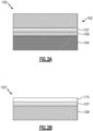
Figures 2a-b schematically shows an article with a joint and a thermoset portion for the article. -
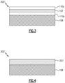
Figure 3 schematically shows another example thermoset portion for the article. -
Figure 4 schematically shows another example thermoset portion for the article. -
Figure 1 schematically illustrates agas turbine engine 20. Thegas turbine engine 20 is disclosed herein as a two-spool turbofan that generally incorporates afan section 22, a compressor section 24, a combustor section 26 and aturbine section 28. Thefan section 22 drives air along a bypass flow path B in a bypass duct defined within ahousing 15 such as a fan case or nacelle, and also drives air along a core flow path C for compression and communication into the combustor section 26 then expansion through theturbine section 28. Although depicted as a two-spool turbofan gas turbine engine in the disclosed non-limiting embodiment, it should be understood that the concepts described herein are not limited to use with two-spool turbofans as the teachings may be applied to other types of turbine engines including three-spool architectures. - The
exemplary engine 20 generally includes alow speed spool 30 and ahigh speed spool 32 mounted for rotation about an engine central longitudinal axis A relative to an enginestatic structure 36 viaseveral bearing systems 38. It should be understood thatvarious bearing systems 38 at various locations may alternatively or additionally be provided, and the location ofbearing systems 38 may be varied as appropriate to the application. - The
low speed spool 30 generally includes aninner shaft 40 that interconnects, a first (or low)pressure compressor 44 and a first (or low)pressure turbine 46. Theinner shaft 40 is connected to thefan 42 through a speed change mechanism, which in exemplarygas turbine engine 20 is illustrated as a gearedarchitecture 48 to drive afan 42 at a lower speed than thelow speed spool 30. Thehigh speed spool 32 includes anouter shaft 50 that interconnects a second (or high)pressure compressor 52 and a second (or high)pressure turbine 54. Acombustor 56 is arranged in theexemplary gas turbine 20 between thehigh pressure compressor 52 and thehigh pressure turbine 54. Amid-turbine frame 57 of the enginestatic structure 36 may be arranged generally between thehigh pressure turbine 54 and thelow pressure turbine 46. Themid-turbine frame 57 further supports bearingsystems 38 in theturbine section 28. Theinner shaft 40 and theouter shaft 50 are concentric and rotate viabearing systems 38 about the engine central longitudinal axis A which is collinear with their longitudinal axes. - The core airflow is compressed by the
low pressure compressor 44 then thehigh pressure compressor 52, mixed and burned with fuel in thecombustor 56, then expanded through thehigh pressure turbine 54 andlow pressure turbine 46. Themid-turbine frame 57 includesairfoils 59 which are in the core airflow path C. Theturbines low speed spool 30 andhigh speed spool 32 in response to the expansion. It will be appreciated that each of the positions of thefan section 22, compressor section 24, combustor section 26,turbine section 28, and fandrive gear system 48 may be varied. For example,gear system 48 may be located aft of the low pressure compressor, or aft of the combustor section 26 or even aft ofturbine section 28, andfan 42 may be positioned forward or aft of the location ofgear system 48. - The
engine 20 in one example is a high-bypass geared aircraft engine. In a further example, theengine 20 bypass ratio is greater than about six (6), with an example embodiment being greater than about ten (10), and can be less than or equal to about 18.0, or more narrowly can be less than or equal to 16.0. The gearedarchitecture 48 is an epicyclic gear train, such as a planetary gear system or other gear system, with a gear reduction ratio of greater than about 2.3. The gear reduction ratio may be less than or equal to 4.0. Thelow pressure turbine 46 has a pressure ratio that is greater than about five. The low pressure turbine pressure ratio can be less than or equal to 13.0, or more narrowly less than or equal to 12.0. In one disclosed embodiment, theengine 20 bypass ratio is greater than about ten (10:1), the fan diameter is significantly larger than that of thelow pressure compressor 44, and thelow pressure turbine 46 has a pressure ratio that is greater than about five 5:1.Low pressure turbine 46 pressure ratio is pressure measured prior to an inlet oflow pressure turbine 46 as related to the pressure at the outlet of thelow pressure turbine 46 prior to an exhaust nozzle. The gearedarchitecture 48 may be an epicycle gear train, such as a planetary gear system or other gear system, with a gear reduction ratio of greater than about 2.3:1 and less than about 5:1. It should be understood, however, that the above parameters are only exemplary of one embodiment of a geared architecture engine and that the present invention is applicable to other gas turbine engines including direct drive turbofans. - A significant amount of thrust is provided by the bypass flow B due to the high bypass ratio. The
fan section 22 of theengine 20 is designed for a particular flight condition -- typically cruise at about 0.8 Mach and about 35,000 feet (10,668 meters). The flight condition of 0.8 Mach and 35,000 ft (10,668 meters), with the engine at its best fuel consumption - also known as "bucket cruise Thrust Specific Fuel Consumption ('TSFC')" - is the industry standard parameter of lbm of fuel being burned divided by lbf of thrust the engine produces at that minimum point. The engine parameters described above and those in this paragraph are measured at this condition unless otherwise specified. "Low fan pressure ratio" is the pressure ratio across the fan blade alone, without a Fan Exit Guide Vane ("FEGV") system. The low fan pressure ratio as disclosed herein according to one non-limiting embodiment is less than about 1.45, or more narrowly greater than or equal to 1.25. "Low corrected fan tip speed" is the actual fan tip speed in ft/sec divided by an industry standard temperature correction of [(Tram °R) / (518.7 °R)]0.5. The "Low corrected fan tip speed" as disclosed herein according to one non-limiting embodiment is less than about 1150.0 ft / second (350.5 meters/second), and can be greater than or equal to 1000.0 ft / second (304.8 meters/second). - Certain components of the
engine 20 may be formed of polymer composites, such as polymer matrix composites (PMCs). One particular example is a nose cone or nose cone cap. In some examples, it may be advantageous to use a hybrid system that includes a combination of thermoset composites and thermoplastic composites to form lightweight high-performance articles such as various components of thegas turbine engine 20. However, conventionally, joining thermoset materials to thermoplastic materials poses certain challenges. Conventional bonding of thermoset to thermoplastic parts can prove to be challenging due to the difficulty of bonding adhesive materials to thermoplastic polymers stemming from inherently low surface free energy of thermoplastics, in addition to requirements for surface preparation and/or longer curing times typically required for adhesive bonding. Fusion bonding is a fast and effective bonding method for thermoplastic components, but is not suitable for conventional thermoset components unless there exists a thermoplastic interlayer, coupling film, or weldable surface on the thermoset component which enables fusion bonding to the thermoplastic component, as in the examples herein. - Additionally, the use of mechanical fasteners such as bolts, screws, clips and the like to join thermoset and thermoplastic composites adds weight to components including these hybrid systems. Mechanical fasteners are therefore not desired for certain applications where lightweight components are preferred. Mechanical fastening methods may also pose challenges and lead to problems arising from drilling with generation of high-stress concentrated areas and/or fiber breakage, galvanic corrosion, mismatch of coefficient of thermal expansion between the composites and the fasteners, and labor intensiveness.
-
Figure 2a shows an example hybridcomposite article 100 according to the present disclosure. The hybridcomposite article 100 includes a thermosetcomposite portion 102 joined to a thermoplasticcomposite portion 104. Any thermoset/thermoplastic materials could be used, but in some examples, the materials include polymeric or ceramic reinforcement, such as fibers, in a polymeric matrix. The thermoset/thermoplastic portions 102/104 are joined at a joint 106. The joint 106 is formed from welded or fused material and avoids the need for mechanical fasteners and/or adhesives. Thearticle 100 also includes at least onethermal barrier 107. - The
thermoplastic portion 104 can include polyetheretherketone (PEEK), polyetherimide (PEI), polyphenylene sulfide (PPS), polysulfone (PSU), polyethersulfone (PES), polyetherketoneketone (PEKK), polyaryletherketone (PAEK), or combinations thereof. Thethermoset portion 102 can be an epoxy-based material, for instance. -
Figure 2b shows the thermoset portion 102' prior to joining with thethermoplastic portion 104. Prior to being joined with thethermoplastic portion 104, the thermoset portion 102' is provided with a weldable surface as follows. Aprepreg 108 of thermoset material such as epoxy is formed according to any known method. Aninterlayer 110 of thermoplastic material is disposed on theprepreg 108. Theinterlayer 110 can be in the form of a film or thin layer, or coating, or in the form of a surface treatment. - The thermoset portion 102' also includes a
thermal barrier 107 arranged between theinterlayer 110 and theprepreg 108. Thethermal barrier 107 includes material with good thermal insulation properties, e.g. better thermal insulation properties than the thermoset portion 102'. For example, thethermal barrier 107 could include ceramic fibers such as carbon fiber or silicon carbide fiber, glass fibers, aramid fibers, oxide fibers, or other known fibers alone or in combination with thermoplastic fibers. In particular examples, thethermal barrier 107 is a fabric of woven fibers or a mat of nonwoven fibers. Thethermal barrier 107 protects the thermoset portion 102' from heat during joining with thethermoplastic portion 104, which is discussed in more detail below. Thethermal barrier 107 thus minimizes degradation of the thermoset portion 102' during the joining process. - The
interlayer 110,thermal barrier 107, and theprepreg 108 are co-cured, e.g., the thermoset portion 102' is subject to curing conditions as appropriate for the particular makeup of theprepreg 108, which would be known in the art. During the co-curing, material from theinterlayer 110,thermal barrier 107, and theprepreg 108 diffuse into one another to consolidate theinterlayer 110,thermal barrier 107, and theprepreg 108 together. In particular, thethermal barrier 107 may be relatively more porous than theprepreg 108, encouraging infiltration ofprepreg 108 material into the pores of thethermal barrier 107. In other examples, an adhesive may also be provided between thethermal barrier 107 and theprepreg 108. - The
interlayer 110 is selected to be chemically compatible with the material of theprepreg 108 and thethermal barrier 107 as well as thethermoplastic portion 104, and to be curable under similar conditions as the material of theprepreg 108. Chemical compatibility, generally, is achieved when there are no or minimal undesirable chemical reactions between the material of theinterlayer 110 and theprepreg 108/thermal barrier 107 and can allow for interdiffusion between materials to promote adhesion. Some examples of materials for theinterlayer 110 are polyetheretherketone (PEEK), polyetherimide (PEI), polyphenylene sulfide (PPS), polysulfone (PSU), polyethersulfone (PES), polyetherketoneketone (PEKK), and polyaryletherketone (PAEK). Theinterlayer 110 can be the same or different material as thethermoplastic portion 104. - In the example of
Figures 2a-b , there is oneinterlayer 110. In another example shown inFigure 3 , the thermoset portion 202' prior to joining with thethermoplastic portion 104 includes twointerlayers 110a/110b, with oneinterlayer 110a/110b disposed on either side of thethermal barrier 107. This example thus includes anadditional interlayer 110b between theprepreg 108 and thethermal barrier 107. Thisadditional interlayer 110b can improve bonding of thethermal barrier 107 to theprepreg 108 by promoting infiltration/diffusion of material between thethermal barrier 107 and theprepreg 108 during co-curing as discussed above. - The
interlayers 110a/110b may be the same or different. At least theouter interlayer 110a is a weldable thermoplastic material, but theadditional interlayer 110b may or may not be a weldable thermoplastic material. In a particular example, theinterlayer 110b between theprepreg 108 and thethermal barrier 107 promotes infiltration/diffusion of material between thethermal barrier 107 and theprepreg 108 during co-curing as discussed above, while theinterlayer 110a promotes welding/fusion with thethermoplastic portion 104. Eitherinterlayer 110a/110b could also be a surface treatment, in another example. Theinterlayer 110a/110b may also act as an adhesion promoting layer or additional thermal barrier layer, may promote bonding of theinterlayer 110a/110b to theprepreg 108 and/or thethermal barrier 107 during co-cure, and/or may provide temperature bridging for joining thethermoplastic component 104 to thethermoset component 102 where thethermoplastic component 104 requires a significantly higher processing temperature compared to thethermoset component 102/interlayer 110/110a. Temperature bridging may improve the joint 106 quality if there exists a large difference in melt temperature between the dissimilar materials of thethermoplastic component 104 andthermoset component 102/interlayer 110/110a during joining in subsequent method steps discussed below. A polymer material with significantly lower melting temperature compared to the other polymer material component will melt early and could lead to a poor bond. - The
additional interlayer 110b may also provide mechanical support to the joint 106, in some examples. - In some examples, the
interlayer 110/110a/110b is coated or otherwise applied onto thethermal barrier 107, and then thethermal barrier 107 with theinterlayer 110/110a/110b is applied to the prepreg. - The
article 100 is formed by arranging thethermoset portion 102 with thethermoplastic portion 104 such that theinterlayer 110, or in examples withmultiple interlayers 110a/110b, theoutermost interlayer 110a, faces thethermoplastic portion 104. Thearticle 100 can then be subjected to any known welding/fusion process such as resistance welding to cause the weldable surface/film 110 to be joined to thethermoplastic portion 104, thus forming the joint 106 to join thethermoset portion 102 to thethermoplastic portion 104. Thethermal barrier 107 protects thethermoset portion 102 from heat during the welding/fusion as discussed above. In addition, thethermal barrier 107 may also provide mechanical support to the joint 106. - In some examples, optional additional joining improvement may be made prior to the welding/fusion process. For instance, the
thermoset portion 102/thermoplastic portion 104 may be treated with a surface treatment to improve adhesion. Such surface treatments are well known in the art. As another example, either of thethermoset portion 102, thethermoplastic portion 104, or both may be provided with features that allow for mechanical interlocking of theportions 102/104.Figure 4 shows another example thermoset portion 302' prior to joining with the thermoplastic portion. In this example, thethermal barrier 207 includes an integrated interlayer. That is, thethermal barrier 207 includes thermoplastic material within it so that thethermal barrier 207 forms a weldable surface on the thermoset portion 302'. This further eliminates the need for additional thermoplastic film interlayer or coupling layer, e.g., theinterlayer 110/110a/110b. The thermoplastic material can be in the form of thermoplastic fibers, or the thermoplastic material can be infiltrated into a fiber array of thethermal barrier 207, for instance. Thethermal barrier 207 is co-cured with theprepreg 108 as in the examples discussed above. In this example,interlayers 110/110a/110b can be omitted or included. In the example ofFigure 4 , thethermal barrier 207 forms the joint 106 when the thermoset portion 302' is joined with thethermoplastic portion 104. - In addition to the other advantage and contributions of the
interlayer 110/110a/110b and/orthermal barrier 207 discussed above, theinterlayer 110/110a/110b and/orthermal barrier 207 may also provide other protections to thethermoset portion 102 such as environmental and chemical protection, mechanical protection like impact resistance and toughness, and electrical insulation. - As used herein, the terms "about" or "approximately" have the typical meaning in the art, however in a particular example "about" and "approximately" can mean deviations of up to 10% of the values described herein.
- Although the different examples are illustrated as having specific components, the examples of this disclosure are not limited to those particular combinations. It is possible to use some of the components or features from any of the embodiments in combination with features or components from any of the other embodiments.
- The foregoing description shall be interpreted as illustrative and not in any limiting sense. A worker of ordinary skill in the art would understand that certain modifications could come within the scope of this disclosure. For these reasons, the following claims should be studied to determine the true scope and content of this disclosure.
Claims (15)
- A thermoset component (102'; 202'; 302') for joining with a thermoplastic component (104), comprising:a thermoset material (108);a weldable surface on the thermoset material (108), the weldable surface including a thermoplastic material; anda thermal barrier (107; 207).
- The thermoset component (102'; 202') of claim 1, wherein the thermoplastic material of the weldable surface is an interlayer (110; 110a) disposed on the thermal barrier (107), and the thermal barrier (107) is arranged between the interlayer (110; 110a) and the thermoset material (108).
- The thermoset component (202') of claim 2, wherein the interlayer (1 10a) is a first interlayer (110a), and further comprising a second interlayer (110b) between the thermal barrier (107) and the thermoset material (108).
- The thermoset component (302') of claim 1, wherein the thermoplastic material of the weldable surface is thermoplastic fibers within the thermal barrier (207).
- The thermoset component (302') of claim 1 or 4, wherein the thermoplastic material of the weldable surface is infiltrated in the thermal barrier (207).
- A hybrid polymeric component (100), comprising:a thermoset portion (102; 102'; 202'; 302');a thermoplastic portion (104) joined to the thermoset portion (102; 102'; 202'; 302') at a welded joint (106); anda thermal barrier (107) between the thermoset portion (102; 102'; 202'; 302') and the thermoplastic portion (104).
- The hybrid polymeric component (100) of claim 6, wherein the thermal barrier (107) is at the joint (106).
- The hybrid polymeric component (100) of claim 6 or 7 or thermoset component (102'; 202'; 302') of any of claims 1 to 5, wherein the thermal barrier (107) comprises ceramic or polymeric fibers.
- The hybrid polymeric component (100) or thermoset component (102'; 202'; 302') of claim 8, wherein the fibers are woven.
- The hybrid polymeric component (100) or thermoset component (102'; 202'; 302') of claim 9, wherein the fibers are nonwoven.
- A method of making a hybrid polymeric component (100), comprising:forming a thermoset portion (102; 102'; 202'; 302') including a thermoset material (108), a weldable surface on the thermoset material (108), the weldable surface including a thermoplastic material, and a thermal barrier (107); andjoining a thermoplastic portion (104) to the thermoset portion (102; 102'; 202'; 302') by welding the thermoplastic portion (104) to the weldable surface.
- The method of claim 11, wherein the thermal barrier (107) comprises ceramic or polymeric fibers.
- The method of claim 11, hybrid polymeric component (100) of claim 6 or 7 or thermoset component (102'; 202'; 302') of any of claims 1 to 5, wherein the thermal barrier (107) comprises carbon fibers.
- The method of any of claims 11 to 13, wherein the thermoplastic material of the weldable surface is thermoplastic fibers within the thermal barrier (107).
- The method of any of claims 11 to 14, wherein the thermoplastic material of the weldable surface is infiltrated in the thermal barrier (107).
Applications Claiming Priority (1)
| Application Number | Priority Date | Filing Date | Title |
|---|---|---|---|
| US17/831,995 US12533756B2 (en) | 2022-06-03 | 2022-06-03 | Polymeric component and method of making the same |
Publications (2)
| Publication Number | Publication Date |
|---|---|
| EP4289605A1 true EP4289605A1 (en) | 2023-12-13 |
| EP4289605B1 EP4289605B1 (en) | 2025-12-31 |
Family
ID=86692726
Family Applications (1)
| Application Number | Title | Priority Date | Filing Date |
|---|---|---|---|
| EP23177205.4A Active EP4289605B1 (en) | 2022-06-03 | 2023-06-05 | POLYMER COMPONENT AND METHOD FOR PRODUCING IT |
Country Status (2)
| Country | Link |
|---|---|
| US (1) | US12533756B2 (en) |
| EP (1) | EP4289605B1 (en) |
Citations (3)
| Publication number | Priority date | Publication date | Assignee | Title |
|---|---|---|---|---|
| EP0633836B1 (en) * | 1992-03-30 | 1997-02-19 | United Technologies Corporation | Heating means for thermoplastic bonding |
| US20110062287A1 (en) * | 2007-01-17 | 2011-03-17 | Airbus Operations Gmbh | Method of Joining a Thermoplastic Material to a Fibre Composite Material |
| US20200086614A1 (en) * | 2018-09-14 | 2020-03-19 | Rohr, Inc. | Component with bonded thermoplastic and thermoset layers |
Family Cites Families (11)
| Publication number | Priority date | Publication date | Assignee | Title |
|---|---|---|---|---|
| US5389184A (en) | 1990-12-17 | 1995-02-14 | United Technologies Corporation | Heating means for thermoplastic bonding |
| US5643390A (en) | 1995-05-04 | 1997-07-01 | The University Of Delaware | Bonding techniques for high performance thermoplastic compositions |
| AUPR673101A0 (en) | 2001-07-31 | 2001-08-23 | Cooperative Research Centre For Advanced Composite Structures Limited | Welding techniques for polymer or polymer composite components |
| US8211268B1 (en) | 2009-03-20 | 2012-07-03 | Milliken & Company | Tie layer compositions for fiber reinforced thermoplastic—thermoset structural element |
| DE102013114829A1 (en) | 2013-12-23 | 2015-06-25 | KTM Technologies GmbH | Fiber-reinforced thermoset component with functional layer for connection to a thermoplastic component |
| JP6179542B2 (en) | 2015-03-19 | 2017-08-16 | トヨタ自動車株式会社 | Resin bonded body, resin bonded body manufacturing method, and vehicle structure |
| EP3124208A1 (en) | 2015-07-31 | 2017-02-01 | AIRBUS HELICOPTERS DEUTSCHLAND GmbH | Method for joining thermoset components |
| AU2018392474A1 (en) | 2017-12-21 | 2020-05-28 | Cytec Industries Inc. | Peel ply for surface preparation and bonding method using the same |
| CN113825625B (en) | 2019-05-10 | 2025-01-28 | 汉高股份有限及两合公司 | Thermosetting composite surface films applied directly to UV treated thermoplastic surfaces and related composite structures |
| DE102020109740A1 (en) | 2020-04-07 | 2021-10-07 | Airbus S.A.S. | Joining process and assembly for an aircraft |
| US20210316527A1 (en) * | 2020-04-08 | 2021-10-14 | The Boeing Company | Interlayer and associated reinforcement structure, composite, and method |
-
2022
- 2022-06-03 US US17/831,995 patent/US12533756B2/en active Active
-
2023
- 2023-06-05 EP EP23177205.4A patent/EP4289605B1/en active Active
Patent Citations (3)
| Publication number | Priority date | Publication date | Assignee | Title |
|---|---|---|---|---|
| EP0633836B1 (en) * | 1992-03-30 | 1997-02-19 | United Technologies Corporation | Heating means for thermoplastic bonding |
| US20110062287A1 (en) * | 2007-01-17 | 2011-03-17 | Airbus Operations Gmbh | Method of Joining a Thermoplastic Material to a Fibre Composite Material |
| US20200086614A1 (en) * | 2018-09-14 | 2020-03-19 | Rohr, Inc. | Component with bonded thermoplastic and thermoset layers |
Also Published As
| Publication number | Publication date |
|---|---|
| US12533756B2 (en) | 2026-01-27 |
| US20230390874A1 (en) | 2023-12-07 |
| EP4289605B1 (en) | 2025-12-31 |
Similar Documents
| Publication | Publication Date | Title |
|---|---|---|
| EP3792454B1 (en) | Intersegment seal for cmc boas assembly | |
| US11047245B2 (en) | CMC component attachment pin | |
| US11105215B2 (en) | Feather seal slot arrangement for a CMC BOAS assembly | |
| US11319827B2 (en) | Intersegment seal for blade outer air seal | |
| US11346363B2 (en) | Composite airfoil for gas turbine | |
| US11384020B2 (en) | Integral ceramic matrix composite fastener with non-polymer rigidization | |
| US20200095880A1 (en) | Featherseal formed of cmc materials | |
| EP3719264A1 (en) | Cmc boas with transverse hook arrangement | |
| EP4289605B1 (en) | POLYMER COMPONENT AND METHOD FOR PRODUCING IT | |
| US11391167B2 (en) | Hybrid airfoil for gas turbine engines | |
| EP3712382B1 (en) | Blade outer air seal assembly with wear liner | |
| EP3712384B1 (en) | Blade outer air seal with seal carrier | |
| US11261971B2 (en) | Double angled brush seal | |
| US11242991B2 (en) | CMC component arrangement and method of manufacture | |
| EP4098844A1 (en) | Hybrid platform manufacturing | |
| EP4053382B1 (en) | Composite inter-blade platform | |
| US11098608B2 (en) | CMC BOAS with internal support structure | |
| US11359505B2 (en) | Nesting CMC components | |
| EP3712383A1 (en) | Cmc blade outer air seal | |
| US11125099B2 (en) | Boas arrangement with double dovetail attachments |
Legal Events
| Date | Code | Title | Description |
|---|---|---|---|
| PUAI | Public reference made under article 153(3) epc to a published international application that has entered the european phase |
Free format text: ORIGINAL CODE: 0009012 |
|
| STAA | Information on the status of an ep patent application or granted ep patent |
Free format text: STATUS: THE APPLICATION HAS BEEN PUBLISHED |
|
| AK | Designated contracting states |
Kind code of ref document: A1 Designated state(s): AL AT BE BG CH CY CZ DE DK EE ES FI FR GB GR HR HU IE IS IT LI LT LU LV MC ME MK MT NL NO PL PT RO RS SE SI SK SM TR |
|
| STAA | Information on the status of an ep patent application or granted ep patent |
Free format text: STATUS: REQUEST FOR EXAMINATION WAS MADE |
|
| 17P | Request for examination filed |
Effective date: 20240611 |
|
| RBV | Designated contracting states (corrected) |
Designated state(s): AL AT BE BG CH CY CZ DE DK EE ES FI FR GB GR HR HU IE IS IT LI LT LU LV MC ME MK MT NL NO PL PT RO RS SE SI SK SM TR |
|
| RIC1 | Information provided on ipc code assigned before grant |
Ipc: B29L 31/30 20060101ALN20250528BHEP Ipc: B29C 65/50 20060101ALI20250528BHEP Ipc: B29C 65/00 20060101ALI20250528BHEP Ipc: B29C 65/48 20060101ALI20250528BHEP Ipc: B29C 65/02 20060101AFI20250528BHEP |
|
| RIC1 | Information provided on ipc code assigned before grant |
Ipc: B29C 65/02 20060101AFI20250618BHEP Ipc: B29C 65/48 20060101ALI20250618BHEP Ipc: B29C 65/00 20060101ALI20250618BHEP Ipc: B29C 65/50 20060101ALI20250618BHEP Ipc: B29L 31/30 20060101ALN20250618BHEP |
|
| GRAP | Despatch of communication of intention to grant a patent |
Free format text: ORIGINAL CODE: EPIDOSNIGR1 |
|
| STAA | Information on the status of an ep patent application or granted ep patent |
Free format text: STATUS: GRANT OF PATENT IS INTENDED |
|
| RIC1 | Information provided on ipc code assigned before grant |
Ipc: B29C 65/02 20060101AFI20250725BHEP Ipc: B29C 65/48 20060101ALI20250725BHEP Ipc: B29C 65/00 20060101ALI20250725BHEP Ipc: B29C 65/50 20060101ALI20250725BHEP Ipc: B29L 31/30 20060101ALN20250725BHEP |
|
| INTG | Intention to grant announced |
Effective date: 20250808 |
|
| GRAS | Grant fee paid |
Free format text: ORIGINAL CODE: EPIDOSNIGR3 |
|
| GRAA | (expected) grant |
Free format text: ORIGINAL CODE: 0009210 |
|
| STAA | Information on the status of an ep patent application or granted ep patent |
Free format text: STATUS: THE PATENT HAS BEEN GRANTED |
|
| AK | Designated contracting states |
Kind code of ref document: B1 Designated state(s): AL AT BE BG CH CY CZ DE DK EE ES FI FR GB GR HR HU IE IS IT LI LT LU LV MC ME MK MT NL NO PL PT RO RS SE SI SK SM TR |
|
| REG | Reference to a national code |
Ref country code: CH Ref legal event code: F10 Free format text: ST27 STATUS EVENT CODE: U-0-0-F10-F00 (AS PROVIDED BY THE NATIONAL OFFICE) Effective date: 20251231 Ref country code: GB Ref legal event code: FG4D |
|
| REG | Reference to a national code |
Ref country code: DE Ref legal event code: R096 Ref document number: 602023010276 Country of ref document: DE |
|
| REG | Reference to a national code |
Ref country code: IE Ref legal event code: FG4D |
|
| REG | Reference to a national code |
Ref country code: LT Ref legal event code: MG9D |
|
| PG25 | Lapsed in a contracting state [announced via postgrant information from national office to epo] |
Ref country code: NO Free format text: LAPSE BECAUSE OF FAILURE TO SUBMIT A TRANSLATION OF THE DESCRIPTION OR TO PAY THE FEE WITHIN THE PRESCRIBED TIME-LIMIT Effective date: 20260331 |
|
| PG25 | Lapsed in a contracting state [announced via postgrant information from national office to epo] |
Ref country code: FI Free format text: LAPSE BECAUSE OF FAILURE TO SUBMIT A TRANSLATION OF THE DESCRIPTION OR TO PAY THE FEE WITHIN THE PRESCRIBED TIME-LIMIT Effective date: 20251231 Ref country code: HR Free format text: LAPSE BECAUSE OF FAILURE TO SUBMIT A TRANSLATION OF THE DESCRIPTION OR TO PAY THE FEE WITHIN THE PRESCRIBED TIME-LIMIT Effective date: 20251231 |
|
| PG25 | Lapsed in a contracting state [announced via postgrant information from national office to epo] |
Ref country code: RS Free format text: LAPSE BECAUSE OF FAILURE TO SUBMIT A TRANSLATION OF THE DESCRIPTION OR TO PAY THE FEE WITHIN THE PRESCRIBED TIME-LIMIT Effective date: 20260331 |
|
| PG25 | Lapsed in a contracting state [announced via postgrant information from national office to epo] |
Ref country code: LV Free format text: LAPSE BECAUSE OF FAILURE TO SUBMIT A TRANSLATION OF THE DESCRIPTION OR TO PAY THE FEE WITHIN THE PRESCRIBED TIME-LIMIT Effective date: 20251231 |
|
| PG25 | Lapsed in a contracting state [announced via postgrant information from national office to epo] |
Ref country code: BG Free format text: LAPSE BECAUSE OF FAILURE TO SUBMIT A TRANSLATION OF THE DESCRIPTION OR TO PAY THE FEE WITHIN THE PRESCRIBED TIME-LIMIT Effective date: 20251231 |
|
| REG | Reference to a national code |
Ref country code: NL Ref legal event code: MP Effective date: 20251231 |