EP4289554A1 - Abrasive belt device - Google Patents
Abrasive belt device Download PDFInfo
- Publication number
- EP4289554A1 EP4289554A1 EP23167975.4A EP23167975A EP4289554A1 EP 4289554 A1 EP4289554 A1 EP 4289554A1 EP 23167975 A EP23167975 A EP 23167975A EP 4289554 A1 EP4289554 A1 EP 4289554A1
- Authority
- EP
- European Patent Office
- Prior art keywords
- lever
- abrasive belt
- roller
- opening
- distance
- Prior art date
- Legal status (The legal status is an assumption and is not a legal conclusion. Google has not performed a legal analysis and makes no representation as to the accuracy of the status listed.)
- Pending
Links
- 238000009434 installation Methods 0.000 claims abstract description 24
- 230000002401 inhibitory effect Effects 0.000 claims abstract description 6
- 238000000034 method Methods 0.000 claims description 11
- 230000006835 compression Effects 0.000 claims description 5
- 238000007906 compression Methods 0.000 claims description 5
- 230000009467 reduction Effects 0.000 claims description 3
- 238000000926 separation method Methods 0.000 claims description 3
- 230000000717 retained effect Effects 0.000 claims description 2
- 230000014759 maintenance of location Effects 0.000 claims 1
- 230000004888 barrier function Effects 0.000 description 4
- 230000003247 decreasing effect Effects 0.000 description 4
- 230000006870 function Effects 0.000 description 4
- 230000000670 limiting effect Effects 0.000 description 4
- 230000008901 benefit Effects 0.000 description 3
- 230000008859 change Effects 0.000 description 3
- 238000010586 diagram Methods 0.000 description 3
- 238000005498 polishing Methods 0.000 description 3
- 230000000295 complement effect Effects 0.000 description 2
- 230000008878 coupling Effects 0.000 description 2
- 238000010168 coupling process Methods 0.000 description 2
- 238000005859 coupling reaction Methods 0.000 description 2
- 230000007704 transition Effects 0.000 description 2
- 229910000831 Steel Inorganic materials 0.000 description 1
- 230000004913 activation Effects 0.000 description 1
- 238000002485 combustion reaction Methods 0.000 description 1
- 230000003467 diminishing effect Effects 0.000 description 1
- 230000005611 electricity Effects 0.000 description 1
- 230000008676 import Effects 0.000 description 1
- 230000006872 improvement Effects 0.000 description 1
- 230000007246 mechanism Effects 0.000 description 1
- 230000004048 modification Effects 0.000 description 1
- 238000012986 modification Methods 0.000 description 1
- 230000002441 reversible effect Effects 0.000 description 1
- 238000004904 shortening Methods 0.000 description 1
- 239000010959 steel Substances 0.000 description 1
- 238000006467 substitution reaction Methods 0.000 description 1
Images



Classifications
-
- B—PERFORMING OPERATIONS; TRANSPORTING
- B24—GRINDING; POLISHING
- B24B—MACHINES, DEVICES, OR PROCESSES FOR GRINDING OR POLISHING; DRESSING OR CONDITIONING OF ABRADING SURFACES; FEEDING OF GRINDING, POLISHING, OR LAPPING AGENTS
- B24B23/00—Portable grinding machines, e.g. hand-guided; Accessories therefor
- B24B23/06—Portable grinding machines, e.g. hand-guided; Accessories therefor with abrasive belts, e.g. with endless travelling belts; Accessories therefor
-
- B—PERFORMING OPERATIONS; TRANSPORTING
- B24—GRINDING; POLISHING
- B24B—MACHINES, DEVICES, OR PROCESSES FOR GRINDING OR POLISHING; DRESSING OR CONDITIONING OF ABRADING SURFACES; FEEDING OF GRINDING, POLISHING, OR LAPPING AGENTS
- B24B21/00—Machines or devices using grinding or polishing belts; Accessories therefor
- B24B21/18—Accessories
- B24B21/20—Accessories for controlling or adjusting the tracking or the tension of the grinding belt
Definitions
- the present disclosure generally relates to power tools and, more particularly, to an improved abrasive-belt apparatus.
- Belt-type power tools can include a motor that turns a pair of drums on which an abrasive belt is mounted. These tools often include an installation channel that permits passage of the abrasive belt during installation and removal. However, the potential for the abrasive belt to break or "walk off' the drums and exit through the installation channel creates challenges in operation. To that end, some abrasive belt devices include a separate, removable shield for covering the installation channel. However, these shields can be burdensome to remove and reinstall. As a consequence, the shields are often disregarded to expedite use of the tool. Improvements in this area are therefore desirable.
- the present disclosure describes example abrasive belt devices and methods relating to abrasive belt devices.
- One or more embodiments disclose an abrasive belt device.
- the abrasive belt device can include first and second rollers that can accommodate an abrasive belt to define a sanding surface.
- the abrasive belt device can include a lever usable to modify a distance between the rollers.
- the abrasive belt device can define an opening through which the belt passes during installation or removal. In a first lever position, the rollers are separated by a first distance that allows the installation or the removal of the belt, and the opening is not covered by the lever, thereby permitting a portion of the belt to pass through the opening.
- the rollers are separated by a second distance, greater than the first distance, that inhibits the installation or the removal of the belt, and the opening is covered by a portion of the lever, thereby inhibiting any portions of the belt from passing through the opening.
- the abrasive belt device of the preceding paragraph can include one or any combination of the features of this paragraph, among others described herein.
- the lever can include a body portion and a tab portion. In the second lever position, the tab portion at least partially covers the opening. The tab portion can extend substantially perpendicular from the body portion.
- the abrasive belt device can include a motorized component operationally coupled to the belt assembly. The motorized component can be configured to rotate at least the first roller when the lever is in the second position and thereby rotate the abrasive belt around the first roller and the second roller.
- the abrasive belt device of any of the preceding paragraphs can include one or any combination of the features of this paragraph, among others described herein.
- the abrasive belt device can include a biasing member positioned between first and second rollers.
- the biasing member can introduce a biasing force against first and second rollers Rotation of the lever about a lever axis can adjust a force applied on the biasing member that opposes the biasing force.
- the biasing member can include a spring. When lever is in the first position, the lever can cause compression of the spring and thereby a reduction in the distance between the first roller and the second roller.
- the abrasive belt device of the preceding paragraph can include one or any combination of the features of this paragraph, among others described herein.
- the lever can include an engagement portion extending substantially perpendicular from the body portion and substantially parallel to the tab portion.
- the engagement portion can include an engagement portion pivotably mounted about a lever axis to a housing of the abrasive belt device.
- the engagement portion can include a section having a curved profile extending from a first notch to a second notch.
- the abrasive belt device can include a follower portion mechanically linked to the engagement portion of the lever.
- the follower portion can be translated according to the curved profile.
- a portion of the follower portion can rest in the first notch when the lever is in the second position.
- the portion of the follower portion can rest in the second notch when the lever is in the first position.
- the follower portion can include a pin. The pin can move perpendicular to the lever axis responsive to movement by the lever.
- the abrasive belt device of the preceding paragraph can include one or any combination of the features of this paragraph, among others described herein. While the lever is in the second position and the abrasive belt is positioned partially around each of the first and the second rollers, the abrasive belt can be retained partially around the first roller and the second roller by the tab portion. While the lever is in the second position, no abrasive belt can be installed on or removed from the abrasive belt device. The first position and the second position can be separated by 90-degrees of rotation of the lever about the lever axis.
- the abrasive belt cannot be installed on the abrasive belt device when the first roller and the second roller are separated by the second distance due to a size of an internal perimeter of the abrasive belt.
- the opening can be a first opening and, during the installation and/or the removal of the abrasive belt, the abrasive belt can pass through a second opening defined by the belt assembly.
- the tab portion In the second position of the lever, the tab portion can at least partially cover the second opening thereby inhibiting any portions of the abrasive belt from passing therebetween.
- the lever can be u-shaped.
- the first position can be referred to as an open position.
- the second position can be referred to as a closed position.
- One or more embodiments disclose a method of using an abrasive belt device.
- the method can include providing an abrasive belt device comprising a first roller, a second roller, and a lever.
- the abrasive belt device can define an opening through which the abrasive belt device can receive a portion of a continuous abrasive belt for placement partially around each of the first roller and the second roller to define a sanding surface.
- a distance between the first roller and the second roller can be based on a rotational position of the lever.
- the method can include, while the lever is positioned in a first position in which a tab portion of the lever does not inhibit any portions of the continuous abrasive belt from passing through the opening and in which the first roller and the second roller are separated by a first distance, installing the continuous abrasive belt onto the abrasive belt device. Installing can include inserting the portion of the continuous abrasive belt through the opening and placing the continuous abrasive belt partially around each of the first roller and the second roller.
- the method can include transitioning the lever from the first position to a second position in which the lever inhibits the continuous abrasive belt from passing through the opening. Transitioning causes the distance between the first roller and the second roller to increase from the first distance to a second distance thereby introducing tension to the continuous abrasive belt.
- abrasive belt device refers to any power tool that includes or can receive an abrasive belt for grinding, burnishing, deburring, sanding, or polishing.
- an abrasive belt device can use compressed air, electricity, or combustion.
- the term abrasive belt device can refer to, but is not limited to, one or more of a band file, a belt sander, an air belt sander, a detailing belt sander, a finishing sander, a strip sander, a file sander, a detailing file sander, or an abrasive belt tool.
- a multi-purpose lever can be used.
- the lever serves as a mechanism to apply or release tension to an abrasive belt installed on the abrasive belt device. For example, rotation of the lever creates longitudinal motion of a distal roller to shift the distal roller further from or closer to a proximal roller and thereby increase or reduce tension on the abrasive belt, if positioned partially around the rollers.
- the lever advantageously serves as a physical barrier that restricts lateral movement of the abrasive belt.
- the abrasive belt device includes an opening in its housing through which a portion of abrasive belt passes for belt installation or removal.
- the lever can be sufficiently proximate to the opening such that, when the lever is in an open position, a tab portion of the lever does not cover the opening and, when the lever is in a closed position, the tab portion of the lever at least partially covers the opening.
- the lever in the open position, does not inhibit installation or removal of the abrasive belt; yet, in the closed position, the lever advantageously functions as a physical barrier that inhibits the abrasive belt from passing through the opening, should the abrasive belt break or "walk off' the rollers during operation.
- the integrated tab portion of the lever advantageously requires an operator of the abrasive belt device to utilize a barrier (i.e., the tab portion) when the abrasive belt device is in an operational state (e.g., when the lever is in the closed position, thereby applying tension to the abrasive belt via the rollers).
- the design of the lever advantageously provides for unobstructed access to the opening when the abrasive belt device is in a nonoperational state (e.g., when the lever is in the open position and little to no tension is applied to the abrasive belt via the rollers).
- the disclosed lever is non-removable from the abrasive belt device during a belt change, thereby eliminating the risk of the tab portion not being reinstalled.
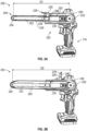
- FIGS. 1A and 1B illustrate perspective views of an example abrasive belt device 100 with a lever 128 positioned in closed and open positions, respectively.
- the abrasive belt device 100 includes a device body 110 and a belt assembly 120. It will be understood that the abrasive belt device 100 can include more, fewer, or different components as desired. Furthermore, it will be understood that FIGS. 1A and 1B represents an example abrasive belt device and other embodiments may include different features or configurations.
- the device body 110 includes a driver 102, a handle 104, and a battery mount 106 (sometimes referred to as a battery foot 106).
- the driver 102 is illustrated as a motorized component (e.g., a motor)
- the handle 104 is illustrated as being positioned between the driver 102 and the battery mount 106
- the battery mount 106 is illustrated as a receiver for a removable battery pack.
- the abrasive belt device 100 may include different features or configurations of the driver 102, the handle 104, and/or the battery mount 106.
- the driver 102 includes an air-powered pneumatic device.
- the abrasive belt device 100 includes more than one and/or a differently positioned handle.
- the abrasive belt device 100 includes an additional handle (not shown) protruding perpendicularly from a distal portion of the belt assembly 120.
- the battery mount 106 includes or attaches to a power plug configured to mate with a power outlet, or the abrasive belt device 100 may not include a battery mount 106.
- the device body 110 and belt assembly 120 are coupled to each other at respective end portions.
- the belt assembly 120 is rotatably mounted to the device body 110 such that the belt assembly 120 can be rotated relative to the device body 110.
- a screw member can be provided to allow adjustable rotational resistance between the device body 110 and belt assembly 120, thereby allowing an operator to interact with the screw member to maneuver the belt assembly 120 into a desired orientation. It will be understood that the screw member is merely an example technique for enabling adjustable rotational resistance and that other techniques may be utilized.
- the belt assembly 120 includes an abrasive belt 124, a contact arm 122 that accommodates the abrasive belt 124, a housing 126, and the lever 128.
- the lever 128 facilitates installation of the abrasive belt 124 on the contact arm 122 or removal of the abrasive belt 124 from the contact arm 122.
- the lever 128 can be rotatable between a plurality of positions. In some cases, the rotation of the lever 128 creates longitudinal motion of the front roller 132 (sometimes referred to as a distal roller 132), thereby increasing or decreasing a length of the contact arm 122, depending on the direction of longitudinal motion.
- the abrasive belt 124 can be installed on the contact arm 122 or, if the abrasive belt 124 is already installed, removed from the contact arm 122.
- the abrasive belt 124 cannot be installed on the contact arm 122 or, if the abrasive belt 124 is already installed, cannot be removed from the contact arm 122.
- the abrasive belt device 100 is equipped with the abrasive belt 124 at least partially around the contact arm 122 and the lever is 128 is oriented in a closed position, thereby applying tension to the abrasive belt 124.
- the driver 102 causes a roller (see roller 232 of FIG. 2A ) of the belt assembly 120 to rotate, thereby causing the abrasive belt 124 to rotate about the contact arm 122.
- the abrasive belt 124 can be used for grinding, burnishing, deburring, sanding, polishing, or the like.
- FIGS. 2A and 2B illustrate side views of an example abrasive belt device 200 with a lever 228 positioned in closed and open positions, respectively.
- a side portion (not shown) of the housing 226 has been removed to increase visibility of components internal to the housing 226.
- the abrasive belt device 200 is an embodiment of the abrasive belt device 100 of FIGS. 1A and 1B .
- the belt assembly 220 includes a contact arm 222, a housing 226, and a lever 228.
- the contact arm 222 includes a first roller 232 at a proximal end, a second roller 234 at a distal end, and a tension assembly 236 positioned between the first roller 232 and the second roller 234.
- the contact arm 222 accommodates an abrasive belt 224 partially around each of the first roller 232 and the second roller 234 to define a sanding surface 244.
- the abrasive belt 224 passes through an opening 246 defined by the belt assembly 220.
- the opening 246 is defined by a groove between a portion of the contact arm 222 (or the side portion (not shown) of the housing 226) and a portion of the housing 226.
- the lever 228 is rotatable or pivotable into a plurality of positions.
- a closed position as illustrated by FIG. 2A
- the centers of the first roller 232 and the second roller 234 are a first distance, D1, apart.
- an open position as illustrated by FIG. 2B
- the primary interior surface of the body portion 229 of the lever 228 is perpendicular to portion of the housing 226.
- the centers of the first roller 232 and the second roller 234 are a second distance, D2, apart.
- the second distance, D2 is shorter than the first distance, D1.
- the difference in distance of D1 and D2 is a result of the impact that the position of the lever 228 has on the contact arm.
- the lever 228 when the lever 228 is in the open position, the lever 228 causes a spring in the tension assembly 236 to be compressed, thereby shortening the length of the contact arm 222.
- the first roller 232 and the second roller 234 are closer together and there is slack in the abrasive belt 224.
- the abrasive belt 224 is taut.
- the tab portion 230 when the lever 228 is in a closed position (sometimes referred to as an operating position), the tab portion 230 partially or fully covers the opening 246.
- the tab portion 230 advantageously inhibits the abrasive belt 224 from passing through the opening 246. In this way, the tab portion 230 inhibits the abrasive belt 224 from undesirable "walking off' the contact arm 222.
- the tab portion 230 can inhibit the abrasive belt 224 from exiting the opening 246 responsive to a break or tear in the abrasive belt 224 during operation of the abrasive belt device 200.
- the lever 228 (and thus the tab portion 230) is not removable from the abrasive belt device 200, at least not without diminishing operationality of the device.
- the disclosed design of the lever 228 advantageously eliminates the risk of not being reinstalled during a belt change.
- the tab portion 230 when the lever 228 is in an open position, the tab portion 230 does not cover the opening 246. In this way, the lever 228 (and, in particular, the tab portion 230) rotates out of the way of the opening 246 to provide uninhibited access to the opening 246, allowing an operator to easily install or remove the abrasive belt 224 through the opening 246.
- FIG. 3 illustrates a side view of a portion of an example abrasive belt device 300.
- the abrasive belt device 300 is an embodiment of the abrasive belt devices 100 and 200 of FIGS. 1 and 2 , respectively.
- the abrasive belt device 300 includes a belt assembly 320 that includes a contact arm 322, an abrasive belt 324 fitted around the contact arm 322, a housing 326, and a lever 328.
- the housing 326 defines a first opening 346 and a second opening 347 through which a portion of abrasive belt 324 passes for belt installation or removal.
- the tab portion 330 has sufficient length 335 to extend across, and at least partially cover, each of the first opening 346 and a second opening 347.
- the tab portion 330 advantageously functions as a physical, barrier that inhibits the abrasive belt from passing through either opening 346 or 347, should the abrasive belt break or "walk off' the rollers during operation.
- FIG. 4 illustrates a cross-sectional side view of a portion of an example abrasive belt device 400.
- the abrasive belt device 400 is an embodiment of the abrasive belt devices 100, 200, and 300 of FIGS. 1A-1B , 2A-2B , and 3 , respectively.
- the abrasive belt device 400 includes clamp screws 462, a cover 464, a guide feature 466, an intermediate arm 468, a contact arm 422, a biasing member 454 positioned between the first and second rollers, and a follower portion 452 that interacts with a curved portion of the lever 428 (see curved portion 514 of FIGS. 5A-5D ).
- the follower portion 452 is biased against the curved profile on the lever 428 by the biasing member 454.
- the follower portion 452 is mechanically linked to the intermediate arm 468.
- the intermediate arm 468 accepts the contact arm 422 and rides along the guide feature 466.
- the contact arm 422 can be replaced or swapped out with a different contact arm, for example by means of a threaded fastener.
- the intermediate arm 468 and the contact arm 422 are collectively referred to as the contact arm 422.
- the follower portion 452 is biased against the engagement portion of the lever 428 such that the follower portion 452 is translated according to the curved profile when the lever 428 is rotated.
- the follower portion 452 biases the biasing member 454 to cause the first and second rollers to move closer together.
- the biasing member 454 includes a spring and the follower 452 includes a pin. In some such cases, when the lever 428 is in an open position, the lever 428 causes compression of the spring and thereby a reduction in the distance between the first roller and the second roller.
- the guide feature 466 (in this case, a steel pin) is rigidly connected to a body portion of the abrasive belt device 400 and allows the front belt assembly (e.g., the intermediate arm 468 and the contact arm 422) to move axially between the first and second positions while maintaining accurate positioning to each other.
- the guide feature 466 is clamped to the housing by means of the clamp screws 462 that run perpendicular to the guide feature 466.
- the clamp screws 462 pass through holes in the guide feature 466, and also though a cover 470.
- the cover 470 can help to distribute a clamping force introduced by the clamp screws 462 to the guide feature 466 and also acts as a cover 470 to define a track for the abrasive belt to be installed.
- the cover 470 can limit access to other areas of the belt assembly.
- the cover 470 is considered to be unremovable from the abrasive belt device 400, since it is difficult or impossible to remove without the use of other tools (e.g., a screwdriver).
- the design of the cover 470 advantageously prevents or limits the likelihood that the cover 470 is removed and not reinstalled during a belt change.
- the abrasive belt device 400 is advantageously configured such that the lever 428 and belt assembly can be assembled all from one side.
- Other designs may include a configuration in which a guide feature gets pressed into the housing and the lever needs to be installed from the reverse side in order to pass by or capture the follower portion that it acts upon.
- FIGS. 5A-5D illustrate bottom perspective, side perspective, front, and top views of an example lever 500.
- a lever 500 can be part of an abrasive belt device, such as the abrasive belt device 100 of FIGS. 1A and 1B .
- the lever 500 can be used to increase or decrease tension in (or length of) a contact arm 222.
- FIGS. 5A-5D represent an example lever and other embodiments may include different features or configurations.
- the lever 500 can include a base portion 502, which can include one or more walls.
- the base portion 502 includes a first surface 503 (sometimes referred to as an interior surface) and a second surface 505 (sometimes referred to as an exterior surface).
- first surface 503 faces toward the housing of the abrasive belt device and the second surface 505 faces away from the housing.
- the base portion 502 is relatively rectangular, and the first surface 503 and the second surface 505 are relatively flat.
- the shape or curative of the base portion 502, the first surface 503, and/or the second surface 505 can vary across embodiments.
- the base portion 502, the first surface 503, and/or the second surface 505 can be curved, square-shaped, circular, etc.
- the base portion 502 and/or at least the first surface 503 is complementary to an exterior shape of a portion of housing (for example, an upper portion of housing 226).
- the first surface 503 can be complementary to an exterior shape of the portion of housing to which it touches.
- the lever 500 includes a tab portion 504.
- the tab portion 504 extends relatively perpendicularly from an edge of the base portion 502 such that a primary surface of the tab portion 504 is substantially perpendicularly from a primary surface of the base portion 502.
- the tab portion 504 can extend from a non-edge of the base portion 502, such as a central region.
- the tab portion 504 includes a narrow body, relative to the body of the base portion 502.
- the tab portion 504 includes the same size body or a wider body, relative to the body of the base portion 502.
- the tab portion 504 is relatively rectangular and relatively flat.
- the shape or curative of the tab portion 504 can vary across embodiments.
- the tab portion 504 can be curved, square-shaped, circular, etc.
- the length 507 of the tab portion 504 can be increased or decreased, depending on the embodiment, for example as shown in FIG. 3 .
- the length 507 of the tab portion 504 can be based on a size or location of the opening(s) through which a portion of abrasive belt must (or will likely) pass for correct belt installation.
- the lever 500 includes a lip 506 located along at least a portion of at least one side of the base portion 502.
- the lip 506 extends in a direction away from the exterior surface 505 of the base portion 502 and is located on an opposite side of the base portion 502 relative to the tab portion 504 and the engagement portion 508.
- the exterior surface 515 of the lip 506 is tilted at an angle of approximately 45 degrees relative to the exterior surface 505 of the base portion 502.
- the angle of the lip 506 can vary across embodiments.
- the lip 506 may extend at an angle between 15-75 degrees, such as 20, 30, 50, 60, or 70 degrees, at approximately 90 degrees, or at an angle greater than 90 degrees.
- the lip 506 is relatively rectangular and relatively flat.
- shape or curative of the lip 506 can vary across embodiments.
- the lip 506 can be curved, square-shaped, circular, etc.
- the lip 506 advantageously aids an operator in repositioning the lever 500 by providing an angled portion for the operator to interface with.
- the lever 500 includes an engagement portion 508.
- the engagement portion 508 extends relatively perpendicularly from a second edge of the base portion 502 such that a primary surface of the engagement portion 508 extends substantially perpendicularly or orthogonally from a primary surface of the base portion 502.
- the engagement portion 508 includes a narrow body, relative to the body of the base portion 502.
- the engagement portion 508 includes the same size body or a wider body, relative to the body of the base portion 502.
- the engagement portion 508 is relatively rectangular and relatively flat.
- the shape or curative of the engagement portion 508 can vary across embodiments.
- the engagement portion 508 can be curved, square-shaped, circular, etc.
- the length 509 of the engagement portion 508, can be increased or decreased, depending on the embodiment.
- the engagement portion 508 can include an engagement member 512.
- the engagement member 512 is a hole through which a pin can be inserted such that the lever 500 can be rotatably mounted to an abrasive belt device. In this way, the lever 500 can be pivoted or rotated about the pin's axis into any of a plurality of positions (e.g., an open position, a closed position, an intermediate position, etc.).
- the engagement member 512 can vary across embodiments.
- the engagement member 512 can include any design configured to mate with a portion of the abrasive belt device. In some cases, the engagement member 512 can form any part of a twist and lock connection.
- the engagement member 512 can be configured to mate or lock together without requiring a twist.
- the engagement member 512 can include a hook and loop fastener, a clamp, a clasp, a buckle, a button, or a hook.
- the engagement member 512 can include a cavity, aperture, or groove configured to receive a protrusion, or can include the protrusion (e.g., for inserting into a hole of the abrasive belt device.
- the lever 500 is relatively U-shaped, with the base portion 502 forming a bottom part of the U-shape, and the tab portion 504 and the engagement portion 508 forming legs of the U-shape.
- the shape of the lever 500 can vary across embodiments.
- the lever 500 can be relatively flat, C-shaped, J-shaped, cylindrical, rectangular, triangular, spherical, conical, or helical or can have a shape that is similar to a prism.
- the engagement portion 508 can include a curved portion 514 (sometimes referred to as a cam feature) configured to transform rotary motion into linear motion to expand or contact the contact arm of the abrasive belt device.
- the curved portion 514 has a curved profile extending from a first notch 521 to a second notch 523.
- a portion of a follower portion e.g., a pin
- the curved portion 514 strikes a follower portion at one or more points on its curved path/perimeter.
- the curved portion 514 can press against a pin and the pin presses against a spring, thereby compressing the spring, thereby causing compression of the spring, and moving the first and second rollers closer together thereby closing the distance between the roller centers.
- the lever 500 is rotatable about the lever axis into any of a plurality of positions.
- the curved portion 514 causes compression of the contact arm and moves the roller centers closer together, allowing a belt to fit partially around the rollers.
- the lever In a closed position, the lever is rotated 90 degrees relative to the open position and the curved portion 514 allows the contact arm to expand.
- the roller center distance In the closed position, the roller center distance is at a second length, which can be a greatest length given the design the abrasive belt device. The second length can be greater than the first length such that a currently installed belt cannot be uninstalled and/or a belt cannot be installed around the rollers.
- the tab portion 504 also at least partially covers the opening thereby inhibiting any portions of the abrasive belt from passing therebetween. In this way, if the belt walks off the rollers or breaks, the tab portion 504 can reduce the likelihood that the belt enters the groove.
- the disclosed lever is usable to control tension applied to an abrasive belt 124 installed in the abrasive belt device 100.
- the disclosed lever 128 includes a tab portion that provides a physical separation between the abrasive belt and the surrounding area.
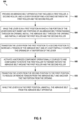
- FIG. 6 illustrates a flow diagram illustrating an embodiment of a routine 600 for using an abrasive belt device, such as any of abrasive belt devices 100, 200, 300, or 400.
- the routine 600 has been associated as being generally performed by an operator on the abrasive belt device 200.
- the following illustrative embodiments should not be construed as limiting.
- the abrasive belt device 200 includes a belt assembly 220 for holding the abrasive belt 224.
- the belt assembly includes, but is not limited to, a housing 226 for housing a portion of the belt assembly 220 and a contact arm 222 for removably receiving the abrasive belt 224.
- the housing 226 includes a first opening 146 and a second opening 147 through which a portion of abrasive belt 224 can be passed.
- the first opening 146 and/or the second opening 147 corresponds to an area between an exterior of the contact arm 222 and an interior of the housing 226.
- the abrasive belt 224 must pass through the first opening 146 and/or the second opening 147 to be removed from the abrasive belt device 200 and/or installed in the abrasive belt device 200.
- the first opening 146 and/or the second opening 147 merely provide a simpler route for installation than other openings.
- the lever 228 is rotatable through a plurality of positions.
- the rotatable range of motion of the lever 228 is limited by mechanical end stops or other physical restraints such that the range of motion of the lever 228 extends between an open position and a closed position that is offset approximately 90 degrees from the open position.
- the open position in the open position (see FIG. 2B ), the primary surface of the base portion of the lever 228 is perpendicular to a surface of the housing 226.
- the open position of the lever 228 causes the roller 132 to contract to a first length, allowing the abrasive belt 224 to be installed thereon.
- the closed position see FIG.
- the primary surface of the base portion of the lever 228 is parallel to closest surface of the housing 226.
- the closed position of the lever 228 causes the roller 132 to extend to a second length that is longer than the first length.
- a plurality of potential lever positions exists between the open position and the closed position.
- portions of the abrasive belt 224 are passed though the openings 246 and 247 and partially around the first roller 232 and the second roller 234.
- the length, D2 of the contact arm 122 is sufficiently short such that the abrasive belt 224 can fit around the contact arm.
- the lever 228 is transitioned from the open position to the closed position.
- an operator can rotate the lever 228 approximately 90 degrees by pressing the lever towards the housing 226.
- a motorized component is activated to cause the abrasive belt to rotate around the first roller and the second roller.
- the activation of the motorized component facilitates grinding, burnishing, deburring, sanding, or polishing via a sanding surface of the exterior of the abrasive belt.
- the lever 228 is transitioned from the closed position to the open position.
- an operator can rotate the lever 228 approximately 90 degrees by pulling the lever away from the housing 226.
- the abrasive belt is removed from the abrasive belt apparatus 200.
- the first roller 232 and the second roller 234 are closer together and there is slack in the abrasive belt 224.
- the lever 228 does not cover the opening. In this way, the operator can easily remove the abrasive belt from the abrasive belt apparatus 200.
- routine 600 can include blocks for installing an abrasive belt, uninstalling the abrasive belt, transitioning the lever from the open position to the closed position (or another position), or transitioning the lever from the closed position to the open position (or another position).
- the words “include,” “can include,” and the like are to be construed in an inclusive sense, as opposed to an exclusive or exhaustive sense; that is to say, in the sense of "including, but not limited to.”
- the terms “connected,” “coupled,” or any variant thereof means any connection or coupling, either direct or indirect, between two or more elements; the coupling or connection between the elements can be physical, logical, or a combination thereof.
- the words “herein,” “above,” “below,” and words of similar import, when used in this application refer to this application as a whole and not to any particular portions of this application.
- words in the above Detailed Description using the singular or plural number may also include the plural or singular number, respectively.
- the word "or” in reference to a list of two or more items covers all of the following interpretations of the word: any one of the items in the list, all of the items in the list, and any combination of the items in the list.
- the term “and/or” in reference to a list of two or more items covers all of the following interpretations of the word: any one of the items in the list, all of the items in the list, and any combination of the items in the list.
- Disjunctive language such as the phrase "at least one of X, Y, or Z," unless specifically stated otherwise, is otherwise understood with the context as used in general to present that an item, term, etc., may be either X, Y, or Z, or any combination thereof (non-limiting examples: X, Y, and/or Z). Thus, such disjunctive language is not generally intended to, and should not, imply that certain embodiments require at least one of X, at least one of Y, or at least one of Z to each be present.
- a device configured to are intended to include one or more recited devices. Such one or more recited devices can also be collectively configured to carry out the stated recitations.
- a processor configured to carry out recitations A, B and C can include a first processor configured to carry out recitation A working in conjunction with a second processor configured to carry out recitations B and C.
- any terms generally associated with circles such as “radius” or “radial” or “diameter” or “circumference” or “circumferential” or any derivatives or similar types of terms are intended to be used to designate any corresponding structure in any type of geometry, not just circular structures.
- radial as applied to another geometric structure should be understood to refer to a direction or distance between a location corresponding to a general geometric center of such structure to a perimeter of such structure
- “diameter” as applied to another geometric structure should be understood to refer to a cross sectional width of such structure
- “circumference” as applied to another geometric structure should be understood to refer to a perimeter region.
Landscapes
- Engineering & Computer Science (AREA)
- Mechanical Engineering (AREA)
- Finish Polishing, Edge Sharpening, And Grinding By Specific Grinding Devices (AREA)
Abstract
Description
- The present disclosure generally relates to power tools and, more particularly, to an improved abrasive-belt apparatus.
- Belt-type power tools can include a motor that turns a pair of drums on which an abrasive belt is mounted. These tools often include an installation channel that permits passage of the abrasive belt during installation and removal. However, the potential for the abrasive belt to break or "walk off' the drums and exit through the installation channel creates challenges in operation. To that end, some abrasive belt devices include a separate, removable shield for covering the installation channel. However, these shields can be burdensome to remove and reinstall. As a consequence, the shields are often disregarded to expedite use of the tool. Improvements in this area are therefore desirable.
- The following disclosure describes non-limiting examples of some embodiments. For instance, other embodiments of the disclosed systems and methods may or may not include the features described herein. Moreover, disclosed advantages and benefits can apply only to certain cases of the invention and should not be used to limit the disclosure. The embodiments disclosed herein each have several aspects, no single one of which is solely responsible for the disclosure's desirable attributes.
- The present disclosure describes example abrasive belt devices and methods relating to abrasive belt devices. One or more embodiments disclose an abrasive belt device. The abrasive belt device can include first and second rollers that can accommodate an abrasive belt to define a sanding surface. The abrasive belt device can include a lever usable to modify a distance between the rollers. The abrasive belt device can define an opening through which the belt passes during installation or removal. In a first lever position, the rollers are separated by a first distance that allows the installation or the removal of the belt, and the opening is not covered by the lever, thereby permitting a portion of the belt to pass through the opening. In a second lever position, the rollers are separated by a second distance, greater than the first distance, that inhibits the installation or the removal of the belt, and the opening is covered by a portion of the lever, thereby inhibiting any portions of the belt from passing through the opening.
- The abrasive belt device of the preceding paragraph can include one or any combination of the features of this paragraph, among others described herein. The lever can include a body portion and a tab portion. In the second lever position, the tab portion at least partially covers the opening. The tab portion can extend substantially perpendicular from the body portion. The abrasive belt device can include a motorized component operationally coupled to the belt assembly. The motorized component can be configured to rotate at least the first roller when the lever is in the second position and thereby rotate the abrasive belt around the first roller and the second roller.
- The abrasive belt device of any of the preceding paragraphs can include one or any combination of the features of this paragraph, among others described herein. The abrasive belt device can include a biasing member positioned between first and second rollers. The biasing member can introduce a biasing force against first and second rollers Rotation of the lever about a lever axis can adjust a force applied on the biasing member that opposes the biasing force. The biasing member can include a spring. When lever is in the first position, the lever can cause compression of the spring and thereby a reduction in the distance between the first roller and the second roller.
- The abrasive belt device of the preceding paragraph can include one or any combination of the features of this paragraph, among others described herein. The lever can include an engagement portion extending substantially perpendicular from the body portion and substantially parallel to the tab portion. The engagement portion can include an engagement portion pivotably mounted about a lever axis to a housing of the abrasive belt device. The engagement portion can include a section having a curved profile extending from a first notch to a second notch. The abrasive belt device can include a follower portion mechanically linked to the engagement portion of the lever. The follower portion can be translated according to the curved profile. A portion of the follower portion can rest in the first notch when the lever is in the second position. The portion of the follower portion can rest in the second notch when the lever is in the first position. The follower portion can include a pin. The pin can move perpendicular to the lever axis responsive to movement by the lever.
- The abrasive belt device of the preceding paragraph can include one or any combination of the features of this paragraph, among others described herein. While the lever is in the second position and the abrasive belt is positioned partially around each of the first and the second rollers, the abrasive belt can be retained partially around the first roller and the second roller by the tab portion. While the lever is in the second position, no abrasive belt can be installed on or removed from the abrasive belt device. The first position and the second position can be separated by 90-degrees of rotation of the lever about the lever axis. The abrasive belt cannot be installed on the abrasive belt device when the first roller and the second roller are separated by the second distance due to a size of an internal perimeter of the abrasive belt. The opening can be a first opening and, during the installation and/or the removal of the abrasive belt, the abrasive belt can pass through a second opening defined by the belt assembly. In the second position of the lever, the tab portion can at least partially cover the second opening thereby inhibiting any portions of the abrasive belt from passing therebetween. The lever can be u-shaped. The first position can be referred to as an open position. The second position can be referred to as a closed position.
- One or more embodiments disclose a method of using an abrasive belt device. The method can include providing an abrasive belt device comprising a first roller, a second roller, and a lever. The abrasive belt device can define an opening through which the abrasive belt device can receive a portion of a continuous abrasive belt for placement partially around each of the first roller and the second roller to define a sanding surface. A distance between the first roller and the second roller can be based on a rotational position of the lever. The method can include, while the lever is positioned in a first position in which a tab portion of the lever does not inhibit any portions of the continuous abrasive belt from passing through the opening and in which the first roller and the second roller are separated by a first distance, installing the continuous abrasive belt onto the abrasive belt device. Installing can include inserting the portion of the continuous abrasive belt through the opening and placing the continuous abrasive belt partially around each of the first roller and the second roller. The method can include transitioning the lever from the first position to a second position in which the lever inhibits the continuous abrasive belt from passing through the opening. Transitioning causes the distance between the first roller and the second roller to increase from the first distance to a second distance thereby introducing tension to the continuous abrasive belt.
- Throughout the drawings, reference numbers can be re-used to indicate correspondence between referenced elements. The drawings are provided to illustrate embodiments of the present disclosure and do not to limit the scope thereof.
-
FIGS. 1A and 1B illustrate perspective views of an example abrasive belt device with a lever positioned in closed and open positions, respectively. -
FIGS. 2A and 2B illustrate side views of an example abrasive belt device with a lever positioned in closed and open positions, respectively. -
FIG. 3 illustrates a side view of a portion of an example abrasive belt device. -
FIG. 4 illustrates a cross-sectional side view of a portion of an example abrasive belt device. -
FIGS. 5A-5D illustrate bottom perspective, side perspective, front, and top views, respectively, of an example lever. -
FIG. 6 illustrates a flow diagram illustrating an embodiment of a routine for using an abrasive belt device. - Although certain embodiments and examples are described below, it will be understood that the disclosure extends beyond the specifically disclosed embodiments and/or uses and obvious modifications and equivalents thereof. Thus, it is intended that the scope of the disclosure herein disclosed should not be limited by any particular embodiments described below.
- As used herein, the term "abrasive belt device" or simply "device" refers to any power tool that includes or can receive an abrasive belt for grinding, burnishing, deburring, sanding, or polishing. Furthermore, as used herein, an abrasive belt device can use compressed air, electricity, or combustion. For example, the term abrasive belt device can refer to, but is not limited to, one or more of a band file, a belt sander, an air belt sander, a detailing belt sander, a finishing sander, a strip sander, a file sander, a detailing file sander, or an abrasive belt tool.
- To improve the usability of an abrasive belt device, a multi-purpose lever can be used. The lever serves as a mechanism to apply or release tension to an abrasive belt installed on the abrasive belt device. For example, rotation of the lever creates longitudinal motion of a distal roller to shift the distal roller further from or closer to a proximal roller and thereby increase or reduce tension on the abrasive belt, if positioned partially around the rollers.
- Furthermore, the lever advantageously serves as a physical barrier that restricts lateral movement of the abrasive belt. In particular, the abrasive belt device includes an opening in its housing through which a portion of abrasive belt passes for belt installation or removal. The lever can be sufficiently proximate to the opening such that, when the lever is in an open position, a tab portion of the lever does not cover the opening and, when the lever is in a closed position, the tab portion of the lever at least partially covers the opening. In this way, in the open position, the lever does not inhibit installation or removal of the abrasive belt; yet, in the closed position, the lever advantageously functions as a physical barrier that inhibits the abrasive belt from passing through the opening, should the abrasive belt break or "walk off' the rollers during operation.
- In contrast to conventional designs that offer separate, removable, and often unused coverings for the opening, the integrated tab portion of the lever advantageously requires an operator of the abrasive belt device to utilize a barrier (i.e., the tab portion) when the abrasive belt device is in an operational state (e.g., when the lever is in the closed position, thereby applying tension to the abrasive belt via the rollers). In addition, the design of the lever advantageously provides for unobstructed access to the opening when the abrasive belt device is in a nonoperational state (e.g., when the lever is in the open position and little to no tension is applied to the abrasive belt via the rollers). Notably, the disclosed lever is non-removable from the abrasive belt device during a belt change, thereby eliminating the risk of the tab portion not being reinstalled.
-
FIGS. 1A and 1B illustrate perspective views of an exampleabrasive belt device 100 with alever 128 positioned in closed and open positions, respectively. Theabrasive belt device 100 includes adevice body 110 and abelt assembly 120. It will be understood that theabrasive belt device 100 can include more, fewer, or different components as desired. Furthermore, it will be understood thatFIGS. 1A and 1B represents an example abrasive belt device and other embodiments may include different features or configurations. - The
device body 110 includes adriver 102, ahandle 104, and a battery mount 106 (sometimes referred to as a battery foot 106). In the illustrated example ofFIGS. 1A and 1B , thedriver 102 is illustrated as a motorized component (e.g., a motor), thehandle 104 is illustrated as being positioned between thedriver 102 and thebattery mount 106, and thebattery mount 106 is illustrated as a receiver for a removable battery pack. However, it will be understood that theabrasive belt device 100 may include different features or configurations of thedriver 102, thehandle 104, and/or thebattery mount 106. For example, in some cases, thedriver 102 includes an air-powered pneumatic device. As another example, in some cases, theabrasive belt device 100 includes more than one and/or a differently positioned handle. For example, in some cases, theabrasive belt device 100 includes an additional handle (not shown) protruding perpendicularly from a distal portion of thebelt assembly 120. As another example, in some cases, thebattery mount 106 includes or attaches to a power plug configured to mate with a power outlet, or theabrasive belt device 100 may not include abattery mount 106. - The
device body 110 andbelt assembly 120 are coupled to each other at respective end portions. In some cases, thebelt assembly 120 is rotatably mounted to thedevice body 110 such that thebelt assembly 120 can be rotated relative to thedevice body 110. For example, a screw member can be provided to allow adjustable rotational resistance between thedevice body 110 andbelt assembly 120, thereby allowing an operator to interact with the screw member to maneuver thebelt assembly 120 into a desired orientation. It will be understood that the screw member is merely an example technique for enabling adjustable rotational resistance and that other techniques may be utilized. - The
belt assembly 120 includes anabrasive belt 124, acontact arm 122 that accommodates theabrasive belt 124, ahousing 126, and thelever 128. As described elsewhere herein, thelever 128 facilitates installation of theabrasive belt 124 on thecontact arm 122 or removal of theabrasive belt 124 from thecontact arm 122. For example, thelever 128 can be rotatable between a plurality of positions. In some cases, the rotation of thelever 128 creates longitudinal motion of the front roller 132 (sometimes referred to as a distal roller 132), thereby increasing or decreasing a length of thecontact arm 122, depending on the direction of longitudinal motion. By decreasing the length of thecontact arm 122 such that an exterior perimeter of thecontact arm 122 is less than an interior perimeter of theabrasive belt 124, theabrasive belt 124 can be installed on thecontact arm 122 or, if theabrasive belt 124 is already installed, removed from thecontact arm 122. In contrast, by increasing the length of thecontact arm 122 such that the exterior perimeter of thecontact arm 122 is approximately equal to or greater than the interior perimeter of theabrasive belt 124, theabrasive belt 124 cannot be installed on thecontact arm 122 or, if theabrasive belt 124 is already installed, cannot be removed from thecontact arm 122. - In an operational state, the
abrasive belt device 100 is equipped with theabrasive belt 124 at least partially around thecontact arm 122 and the lever is 128 is oriented in a closed position, thereby applying tension to theabrasive belt 124. During operation of theabrasive belt device 100 while in the operational state, thedriver 102 causes a roller (seeroller 232 ofFIG. 2A ) of thebelt assembly 120 to rotate, thereby causing theabrasive belt 124 to rotate about thecontact arm 122. In this way, theabrasive belt 124 can be used for grinding, burnishing, deburring, sanding, polishing, or the like. -
FIGS. 2A and 2B illustrate side views of an exampleabrasive belt device 200 with alever 228 positioned in closed and open positions, respectively. In these examples, a side portion (not shown) of thehousing 226 has been removed to increase visibility of components internal to thehousing 226. Theabrasive belt device 200 is an embodiment of theabrasive belt device 100 ofFIGS. 1A and 1B . - The
belt assembly 220 includes acontact arm 222, ahousing 226, and alever 228. Thecontact arm 222 includes afirst roller 232 at a proximal end, asecond roller 234 at a distal end, and atension assembly 236 positioned between thefirst roller 232 and thesecond roller 234. Thecontact arm 222 accommodates anabrasive belt 224 partially around each of thefirst roller 232 and thesecond roller 234 to define asanding surface 244. During installation and/or removal of theabrasive belt 224, theabrasive belt 224 passes through anopening 246 defined by thebelt assembly 220. In particular, in this example, theopening 246 is defined by a groove between a portion of the contact arm 222 (or the side portion (not shown) of the housing 226) and a portion of thehousing 226. - As described herein, the
lever 228 is rotatable or pivotable into a plurality of positions. In a closed position (as illustrated byFIG. 2A ), at least a portion of a primary interior surface of thebody portion 229 of thelever 228 is flush (and parallel) with a portion of thehousing 226. Furthermore, in the closed position, the centers of thefirst roller 232 and thesecond roller 234 are a first distance, D1, apart. In an open position (as illustrated byFIG. 2B ), which is separated by 90-degrees of rotation with the closed position, the primary interior surface of thebody portion 229 of thelever 228 is perpendicular to portion of thehousing 226. Furthermore, in the closed position, the centers of thefirst roller 232 and thesecond roller 234 are a second distance, D2, apart. - As shown, the second distance, D2, is shorter than the first distance, D1. The difference in distance of D1 and D2 is a result of the impact that the position of the
lever 228 has on the contact arm. In particular, as described in more detail herein, when thelever 228 is in the open position, thelever 228 causes a spring in thetension assembly 236 to be compressed, thereby shortening the length of thecontact arm 222. As a result, thefirst roller 232 and thesecond roller 234 are closer together and there is slack in theabrasive belt 224. In contrast, in the closed position, theabrasive belt 224 is taut. - Referring again to
FIG. 2A , when thelever 228 is in a closed position (sometimes referred to as an operating position), thetab portion 230 partially or fully covers theopening 246. By covering theopening 246, thetab portion 230 advantageously inhibits theabrasive belt 224 from passing through theopening 246. In this way, thetab portion 230 inhibits theabrasive belt 224 from undesirable "walking off' thecontact arm 222. Thetab portion 230 can inhibit theabrasive belt 224 from exiting theopening 246 responsive to a break or tear in theabrasive belt 224 during operation of theabrasive belt device 200. Furthermore, unlike conventional shields or covers, the lever 228 (and thus the tab portion 230) is not removable from theabrasive belt device 200, at least not without diminishing operationality of the device. In this way, the disclosed design of thelever 228 advantageously eliminates the risk of not being reinstalled during a belt change. - Referring again to
FIG. 2B , when thelever 228 is in an open position, thetab portion 230 does not cover theopening 246. In this way, the lever 228 (and, in particular, the tab portion 230) rotates out of the way of theopening 246 to provide uninhibited access to theopening 246, allowing an operator to easily install or remove theabrasive belt 224 through theopening 246. -
FIG. 3 illustrates a side view of a portion of an exampleabrasive belt device 300. Theabrasive belt device 300 is an embodiment of theabrasive belt devices FIGS. 1 and2 , respectively. In this example, theabrasive belt device 300 includes abelt assembly 320 that includes acontact arm 322, anabrasive belt 324 fitted around thecontact arm 322, ahousing 326, and alever 328. Thehousing 326 defines afirst opening 346 and asecond opening 347 through which a portion ofabrasive belt 324 passes for belt installation or removal. In contrast to theabrasive belt device 200 ofFIGS. 2A and 2B , in this example, thetab portion 330 hassufficient length 335 to extend across, and at least partially cover, each of thefirst opening 346 and asecond opening 347. In this way, thetab portion 330 advantageously functions as a physical, barrier that inhibits the abrasive belt from passing through eitheropening -
FIG. 4 illustrates a cross-sectional side view of a portion of an exampleabrasive belt device 400. Theabrasive belt device 400 is an embodiment of theabrasive belt devices FIGS. 1A-1B ,2A-2B , and3 , respectively. In this example, theabrasive belt device 400 includes clamp screws 462, acover 464, aguide feature 466, anintermediate arm 468, acontact arm 422, a biasingmember 454 positioned between the first and second rollers, and afollower portion 452 that interacts with a curved portion of the lever 428 (seecurved portion 514 ofFIGS. 5A-5D ). - The
follower portion 452 is biased against the curved profile on thelever 428 by the biasingmember 454. In addition, thefollower portion 452 is mechanically linked to theintermediate arm 468. In some cases, theintermediate arm 468 accepts thecontact arm 422 and rides along theguide feature 466. In some cases, thecontact arm 422 can be replaced or swapped out with a different contact arm, for example by means of a threaded fastener. In some cases, theintermediate arm 468 and thecontact arm 422 are collectively referred to as thecontact arm 422. Thefollower portion 452 is biased against the engagement portion of thelever 428 such that thefollower portion 452 is translated according to the curved profile when thelever 428 is rotated. Upon translation of thefollower portion 452, thefollower portion 452 biases the biasingmember 454 to cause the first and second rollers to move closer together. In the illustrated example, the biasingmember 454 includes a spring and thefollower 452 includes a pin. In some such cases, when thelever 428 is in an open position, thelever 428 causes compression of the spring and thereby a reduction in the distance between the first roller and the second roller. - The guide feature 466 (in this case, a steel pin) is rigidly connected to a body portion of the
abrasive belt device 400 and allows the front belt assembly (e.g., theintermediate arm 468 and the contact arm 422) to move axially between the first and second positions while maintaining accurate positioning to each other. In this example, theguide feature 466 is clamped to the housing by means of the clamp screws 462 that run perpendicular to theguide feature 466. Furthermore, in this example, the clamp screws 462 pass through holes in theguide feature 466, and also though acover 470. Thecover 470 can help to distribute a clamping force introduced by the clamp screws 462 to theguide feature 466 and also acts as acover 470 to define a track for the abrasive belt to be installed. In addition, thecover 470 can limit access to other areas of the belt assembly. In some cases, thecover 470 is considered to be unremovable from theabrasive belt device 400, since it is difficult or impossible to remove without the use of other tools (e.g., a screwdriver). In this way, the design of thecover 470 advantageously prevents or limits the likelihood that thecover 470 is removed and not reinstalled during a belt change. Furthermore, in this example, theabrasive belt device 400 is advantageously configured such that thelever 428 and belt assembly can be assembled all from one side. Other designs may include a configuration in which a guide feature gets pressed into the housing and the lever needs to be installed from the reverse side in order to pass by or capture the follower portion that it acts upon. -
FIGS. 5A-5D illustrate bottom perspective, side perspective, front, and top views of anexample lever 500. As described herein, alever 500 can be part of an abrasive belt device, such as theabrasive belt device 100 ofFIGS. 1A and 1B . With reference toFIG. 2 , thelever 500 can be used to increase or decrease tension in (or length of) acontact arm 222. It will be understood thatFIGS. 5A-5D represent an example lever and other embodiments may include different features or configurations. - The
lever 500 can include abase portion 502, which can include one or more walls. Thebase portion 502 includes a first surface 503 (sometimes referred to as an interior surface) and a second surface 505 (sometimes referred to as an exterior surface). When thelever 500 is coupled to an abrasive belt device and in a closed position, thefirst surface 503 faces toward the housing of the abrasive belt device and thesecond surface 505 faces away from the housing. In the illustrated implementation, thebase portion 502 is relatively rectangular, and thefirst surface 503 and thesecond surface 505 are relatively flat. However, it will be appreciated that the shape or curative of thebase portion 502, thefirst surface 503, and/or thesecond surface 505 can vary across embodiments. For example, thebase portion 502, thefirst surface 503, and/or thesecond surface 505 can be curved, square-shaped, circular, etc. In some cases, thebase portion 502 and/or at least thefirst surface 503 is complementary to an exterior shape of a portion of housing (for example, an upper portion of housing 226). For example, in instances in which thefirst surface 503 contacts the housing during use of the abrasive belt device, thefirst surface 503 can be complementary to an exterior shape of the portion of housing to which it touches. - The
lever 500 includes atab portion 504. In the illustrated example, thetab portion 504 extends relatively perpendicularly from an edge of thebase portion 502 such that a primary surface of thetab portion 504 is substantially perpendicularly from a primary surface of thebase portion 502. In other examples, thetab portion 504 can extend from a non-edge of thebase portion 502, such as a central region. In the illustrated example, thetab portion 504 includes a narrow body, relative to the body of thebase portion 502. In other examples, thetab portion 504 includes the same size body or a wider body, relative to the body of thebase portion 502. In the illustrated example, thetab portion 504 is relatively rectangular and relatively flat. However, it will be appreciated that the shape or curative of thetab portion 504 can vary across embodiments. For example, thetab portion 504 can be curved, square-shaped, circular, etc. Furthermore, thelength 507 of thetab portion 504, can be increased or decreased, depending on the embodiment, for example as shown inFIG. 3 . In some cases, thelength 507 of thetab portion 504 can be based on a size or location of the opening(s) through which a portion of abrasive belt must (or will likely) pass for correct belt installation. - The
lever 500 includes alip 506 located along at least a portion of at least one side of thebase portion 502. Thelip 506 extends in a direction away from theexterior surface 505 of thebase portion 502 and is located on an opposite side of thebase portion 502 relative to thetab portion 504 and theengagement portion 508. In the illustrated example, theexterior surface 515 of thelip 506 is tilted at an angle of approximately 45 degrees relative to theexterior surface 505 of thebase portion 502. However, it will be appreciated that the angle of thelip 506 can vary across embodiments. For example, thelip 506 may extend at an angle between 15-75 degrees, such as 20, 30, 50, 60, or 70 degrees, at approximately 90 degrees, or at an angle greater than 90 degrees. In the illustrated example, thelip 506 is relatively rectangular and relatively flat. However, it will be appreciated that the shape or curative of thelip 506 can vary across embodiments. For example, thelip 506 can be curved, square-shaped, circular, etc. In some cases, thelip 506 advantageously aids an operator in repositioning thelever 500 by providing an angled portion for the operator to interface with. - The
lever 500 includes anengagement portion 508. In the illustrated example, theengagement portion 508 extends relatively perpendicularly from a second edge of thebase portion 502 such that a primary surface of theengagement portion 508 extends substantially perpendicularly or orthogonally from a primary surface of thebase portion 502. In the illustrated example, theengagement portion 508 includes a narrow body, relative to the body of thebase portion 502. In other examples, theengagement portion 508 includes the same size body or a wider body, relative to the body of thebase portion 502. In the illustrated example, theengagement portion 508 is relatively rectangular and relatively flat. However, it will be appreciated that the shape or curative of theengagement portion 508 can vary across embodiments. For example, theengagement portion 508 can be curved, square-shaped, circular, etc. Furthermore, thelength 509 of theengagement portion 508, can be increased or decreased, depending on the embodiment. - The
engagement portion 508 can include anengagement member 512. In the illustrated implementation, theengagement member 512 is a hole through which a pin can be inserted such that thelever 500 can be rotatably mounted to an abrasive belt device. In this way, thelever 500 can be pivoted or rotated about the pin's axis into any of a plurality of positions (e.g., an open position, a closed position, an intermediate position, etc.). However, it will be appreciated that theengagement member 512 can vary across embodiments. For example, theengagement member 512 can include any design configured to mate with a portion of the abrasive belt device. In some cases, theengagement member 512 can form any part of a twist and lock connection. As another example, theengagement member 512 can be configured to mate or lock together without requiring a twist. For instance, theengagement member 512 can include a hook and loop fastener, a clamp, a clasp, a buckle, a button, or a hook. As another example, theengagement member 512 can include a cavity, aperture, or groove configured to receive a protrusion, or can include the protrusion (e.g., for inserting into a hole of the abrasive belt device. - In the illustrated implementation, the
lever 500 is relatively U-shaped, with thebase portion 502 forming a bottom part of the U-shape, and thetab portion 504 and theengagement portion 508 forming legs of the U-shape. However, it will be appreciated that the shape of thelever 500 can vary across embodiments. For example, thelever 500 can be relatively flat, C-shaped, J-shaped, cylindrical, rectangular, triangular, spherical, conical, or helical or can have a shape that is similar to a prism. - The
engagement portion 508 can include a curved portion 514 (sometimes referred to as a cam feature) configured to transform rotary motion into linear motion to expand or contact the contact arm of the abrasive belt device. Thecurved portion 514 has a curved profile extending from afirst notch 521 to asecond notch 523. A portion of a follower portion (e.g., a pin) rests in thefirst notch 521 when thelever 500 is in the open position, and the portion of the follower portion rests in thesecond notch 523 when thelever 500 is in the closed position. In use, thecurved portion 514 strikes a follower portion at one or more points on its curved path/perimeter. In instances in which the contact arm comprises a spring-loaded assembly, thecurved portion 514 can press against a pin and the pin presses against a spring, thereby compressing the spring, thereby causing compression of the spring, and moving the first and second rollers closer together thereby closing the distance between the roller centers. - As mentioned herein, the
lever 500 is rotatable about the lever axis into any of a plurality of positions. In an open position, thecurved portion 514 causes compression of the contact arm and moves the roller centers closer together, allowing a belt to fit partially around the rollers. In a closed position, the lever is rotated 90 degrees relative to the open position and thecurved portion 514 allows the contact arm to expand. In the closed position, the roller center distance is at a second length, which can be a greatest length given the design the abrasive belt device. The second length can be greater than the first length such that a currently installed belt cannot be uninstalled and/or a belt cannot be installed around the rollers. Thetab portion 504 also at least partially covers the opening thereby inhibiting any portions of the abrasive belt from passing therebetween. In this way, if the belt walks off the rollers or breaks, thetab portion 504 can reduce the likelihood that the belt enters the groove. - As described herein, the disclosed lever is usable to control tension applied to an
abrasive belt 124 installed in theabrasive belt device 100. Furthermore, the disclosedlever 128 includes a tab portion that provides a physical separation between the abrasive belt and the surrounding area. -
FIG. 6 illustrates a flow diagram illustrating an embodiment of a routine 600 for using an abrasive belt device, such as any ofabrasive belt devices abrasive belt device 200. However, the following illustrative embodiments should not be construed as limiting. - At
block 602, theabrasive belt device 200 is provided. As described herein, theabrasive belt device 200 includes abelt assembly 220 for holding theabrasive belt 224. The belt assembly includes, but is not limited to, ahousing 226 for housing a portion of thebelt assembly 220 and acontact arm 222 for removably receiving theabrasive belt 224. To facilitate installation and/or removal of theabrasive belt 224 from theabrasive belt device 200, thehousing 226 includes a first opening 146 and a second opening 147 through which a portion ofabrasive belt 224 can be passed. In some cases, the first opening 146 and/or the second opening 147 corresponds to an area between an exterior of thecontact arm 222 and an interior of thehousing 226. In some cases, given the design of theabrasive belt device 200, theabrasive belt 224 must pass through the first opening 146 and/or the second opening 147 to be removed from theabrasive belt device 200 and/or installed in theabrasive belt device 200. Alternatively, in some cases, the first opening 146 and/or the second opening 147 merely provide a simpler route for installation than other openings. - As described herein, the
lever 228 is rotatable through a plurality of positions. In some cases, the rotatable range of motion of thelever 228 is limited by mechanical end stops or other physical restraints such that the range of motion of thelever 228 extends between an open position and a closed position that is offset approximately 90 degrees from the open position. As described herein, in the open position (seeFIG. 2B ), the primary surface of the base portion of thelever 228 is perpendicular to a surface of thehousing 226. In addition, the open position of thelever 228 causes theroller 132 to contract to a first length, allowing theabrasive belt 224 to be installed thereon. Furthermore, in the closed position (seeFIG. 2A ), the primary surface of the base portion of thelever 228 is parallel to closest surface of thehousing 226. In addition, the closed position of thelever 228 causes theroller 132 to extend to a second length that is longer than the first length. In some cases, a plurality of potential lever positions exists between the open position and the closed position. - At
block 604, while thelever 228 in the open position, portions of theabrasive belt 224 are passed though theopenings 246 and 247 and partially around thefirst roller 232 and thesecond roller 234. As described herein, while thelever 228 in the open position, the length, D2, of thecontact arm 122 is sufficiently short such that theabrasive belt 224 can fit around the contact arm. - At
block 606, thelever 228 is transitioned from the open position to the closed position. As described herein, in some cases, to transition thelever 228 from the open position to the closed position, an operator can rotate thelever 228 approximately 90 degrees by pressing the lever towards thehousing 226. - At
block 608, a motorized component is activated to cause the abrasive belt to rotate around the first roller and the second roller. As described herein, the activation of the motorized component facilitates grinding, burnishing, deburring, sanding, or polishing via a sanding surface of the exterior of the abrasive belt. - At
block 610, thelever 228 is transitioned from the closed position to the open position. As described herein, in some cases, to transition thelever 228 from the closed position to the open position, an operator can rotate thelever 228 approximately 90 degrees by pulling the lever away from thehousing 226. - At
block 612, while thelever 228 is in the open position, the abrasive belt is removed from theabrasive belt apparatus 200. As described herein, in the open position, thefirst roller 232 and thesecond roller 234 are closer together and there is slack in theabrasive belt 224. In addition, thelever 228 does not cover the opening. In this way, the operator can easily remove the abrasive belt from theabrasive belt apparatus 200. - It will be understood that the various blocks described herein can be implemented in a variety of orders. Furthermore, it will be understood that fewer, more, or different blocks can be used as part of the routine 600. For example, the routine 600 can include blocks for installing an abrasive belt, uninstalling the abrasive belt, transitioning the lever from the open position to the closed position (or another position), or transitioning the lever from the closed position to the open position (or another position).
- Conditional language, such as, among others, "can," "could," "might," or "may," unless specifically stated otherwise, or otherwise understood within the context as used, is generally intended to convey that certain embodiments include, while other embodiments do not include, certain features, elements, and/or steps. Thus, such conditional language is not generally intended to imply that features, elements and/or steps are in any way required for one or more embodiments or that one or more embodiments necessarily include logic for deciding, with or without user input or prompting, whether these features, elements and/or steps are included or are to be performed in any particular embodiment.
- Unless the context clearly requires otherwise, throughout the description and the claims, the words "include," "can include," and the like are to be construed in an inclusive sense, as opposed to an exclusive or exhaustive sense; that is to say, in the sense of "including, but not limited to." As used herein, the terms "connected," "coupled," or any variant thereof means any connection or coupling, either direct or indirect, between two or more elements; the coupling or connection between the elements can be physical, logical, or a combination thereof. Additionally, the words "herein," "above," "below," and words of similar import, when used in this application, refer to this application as a whole and not to any particular portions of this application. Where the context permits, words in the above Detailed Description using the singular or plural number may also include the plural or singular number, respectively. The word "or" in reference to a list of two or more items, covers all of the following interpretations of the word: any one of the items in the list, all of the items in the list, and any combination of the items in the list. Likewise the term "and/or" in reference to a list of two or more items, covers all of the following interpretations of the word: any one of the items in the list, all of the items in the list, and any combination of the items in the list.
- Depending on the embodiment, certain operations, acts, events, or functions of any of the routines described elsewhere herein can be performed in a different sequence, can be added, merged, or left out altogether (non-limiting example: not all are necessary for the practice of the algorithms). Moreover, in certain embodiments, operations, acts, functions, or events can be performed concurrently, rather than sequentially.
- These and other changes can be made to the invention in light of the above Detailed Description. While the above description describes certain examples of the invention, and describes the best mode contemplated, no matter how detailed the above appears in text, the invention can be practiced in many ways. Details of the system may vary considerably in its specific implementation, while still being encompassed by the invention disclosed herein. As noted above, particular terminology used when describing certain features or aspects of the invention should not be taken to imply that the terminology is being redefined herein to be restricted to any specific characteristics, features, or aspects of the invention with which that terminology is associated. In general, the terms used in the following claims should not be construed to limit the invention to the specific examples disclosed in the specification, unless the above Detailed Description section explicitly defines such terms. Accordingly, the actual scope of the invention encompasses not only the disclosed examples, but also all equivalent ways of practicing or implementing the invention under the claims.
- Disjunctive language such as the phrase "at least one of X, Y, or Z," unless specifically stated otherwise, is otherwise understood with the context as used in general to present that an item, term, etc., may be either X, Y, or Z, or any combination thereof (non-limiting examples: X, Y, and/or Z). Thus, such disjunctive language is not generally intended to, and should not, imply that certain embodiments require at least one of X, at least one of Y, or at least one of Z to each be present.
- Unless otherwise explicitly stated, articles such as "a" or "an" should generally be interpreted to include one or more described items. Accordingly, phrases such as "a device configured to" are intended to include one or more recited devices. Such one or more recited devices can also be collectively configured to carry out the stated recitations. For example, "a processor configured to carry out recitations A, B and C" can include a first processor configured to carry out recitation A working in conjunction with a second processor configured to carry out recitations B and C.
- While the above detailed description has shown, described, and pointed out novel features as applied to various embodiments, it can be understood that various omissions, substitutions, and changes in the form and details of the devices or algorithms illustrated can be made without departing from the spirit of the disclosure. As can be recognized, certain embodiments described elsewhere herein can be embodied within a form that does not provide all of the features and benefits set forth herein, as some features can be used or practiced separately from others. The scope of certain embodiments disclosed herein is indicated by the appended claims rather than by the foregoing description. All changes which come within the meaning and range of equivalency of the claims are to be embraced within their scope.
- Any terms generally associated with circles, such as "radius" or "radial" or "diameter" or "circumference" or "circumferential" or any derivatives or similar types of terms are intended to be used to designate any corresponding structure in any type of geometry, not just circular structures. For example, "radial" as applied to another geometric structure should be understood to refer to a direction or distance between a location corresponding to a general geometric center of such structure to a perimeter of such structure; "diameter" as applied to another geometric structure should be understood to refer to a cross sectional width of such structure; and "circumference" as applied to another geometric structure should be understood to refer to a perimeter region. Nothing in this specification or drawings should be interpreted to limit these terms to only circles or circular structures.
Claims (15)
- An abrasive belt device comprising:a belt assembly comprising a first roller and a second roller, wherein the belt assembly accommodates an abrasive belt partially around each of the first and the second rollers to define a sanding surface, and wherein during installation and/or removal of the abrasive belt, the abrasive belt passes through an opening defined by the belt assembly; anda lever comprising a body portion and a tab portion, wherein the lever is rotatable through a plurality of positions and usable to modify a distance between the first roller and the second roller to facilitate installation, removal, and/or retention of the abrasive belt relative to the belt assembly,wherein a first position of the lever corresponds to a first distance between the first roller and the second roller, wherein separation of first roller and the second roller by the first distance enables the installation and/or the removal of the abrasive belt, and wherein in the first position of the lever, the opening is not covered by the tab portion thereby permitting a portion of the abrasive belt to pass therebetween,wherein a second position of the lever corresponds to a second distance between the first roller and the second roller, wherein the second distance is greater than the first distance, wherein separation of first roller and the second roller by the second distance inhibits the installation and/or the removal of the abrasive belt, and wherein in the second position of the lever, the tab portion at least partially covers the opening thereby inhibiting any portions of the abrasive belt from passing therebetween.
- The device of Claim 1, further comprising a motorized component operationally coupled to the belt assembly, the motorized component configured to rotate at least the first roller when the lever is in the second position and thereby rotate the abrasive belt around the first roller and the second roller.
- The device of Claim 1, further comprising a biasing member positioned between first and second rollers, wherein the biasing member introduces a biasing force against first and second rollers, wherein rotation of the lever about a lever axis adjusts a force applied on the biasing member that opposes the biasing force.
- The device of Claim 3, wherein the biasing member includes a spring, and wherein when the lever is in the first position the lever causes compression of the spring and thereby a reduction in the distance between the first roller and the second roller.
- The device of Claim 1, wherein the tab portion of the lever extends substantially perpendicular from the body portion, wherein the lever further comprises an engagement portion extending substantially perpendicular from the body portion and substantially parallel to the tab portion, wherein the engagement portion comprises an engagement portion pivotably mounted about a lever axis to a housing of the device.
- The device of Claim 5, wherein the engagement portion comprises a section having a curved profile extending from a first notch to a second notch, and wherein the device further comprises a follower portion mechanically linked to the engagement portion of the lever, wherein the follower portion is translated according to the curved profile, wherein a portion of the follower portion rests in the first notch when the lever is in the second position, and wherein the portion of the follower portion rests in the second notch when the lever is in the first position.
- The device of Claim 6, wherein the follower portion includes a pin, wherein the pin moves perpendicular to the lever axis responsive to movement by the lever.
- The device of Claim 1, wherein, while the lever is in the second position:-i) when the abrasive belt is positioned partially around each of the first and the second rollers, the abrasive belt is retained partially around the first roller and the second roller by the tab portion; and/orii) no abrasive belt can be installed on or removed from the device.
- The device of Claim 1, wherein in first position and the second position are separated by 90-degrees of rotation of the lever about the lever axis.
- The device of Claim 1, wherein the abrasive belt cannot be installed on the device when the first roller and the second roller are separated by the second distance due to a size of an internal perimeter of the abrasive belt.
- The device of Claim 1, wherein the opening is a first opening, wherein during the installation and/or the removal of the abrasive belt, the abrasive belt passes through a second opening defined by the belt assembly, wherein in the second position of the lever, the tab portion at least partially covers the second opening thereby inhibiting any portions of the abrasive belt from passing therebetween.
- The device of Claim 1, wherein the lever is u-shaped and/or wherein the first position is an open position, and wherein the second position is a closed position.
- A method of using an abrasive belt device comprising:providing an abrasive belt device comprising a first roller, a second roller, and a lever, wherein the abrasive belt device defines an opening through which the abrasive belt device receives a portion of a continuous abrasive belt for placement partially around each of the first roller and the second roller to define a sanding surface, wherein a distance between the first roller and the second roller is based on a rotational position of the lever;while the lever is positioned in a first position in which a tab portion of the lever does not inhibit any portions of the continuous abrasive belt from passing through the opening and in which the first roller and the second roller are separated by a first distance, installing the continuous abrasive belt onto the abrasive belt device, wherein said installing comprises inserting the portion of the continuous abrasive belt through the opening and placing the continuous abrasive belt partially around each of the first roller and the second roller; andtransitioning the lever from the first position to a second position in which the lever inhibits the continuous abrasive belt from passing through the opening, wherein said transitioning causes the distance between the first roller and the second roller to increase from the first distance to a second distance thereby introducing tension to the continuous abrasive belt.
- The method of Claim 13, further comprising operating the abrasive belt device while the lever is in the second position, wherein during said operating a tab portion of the lever inhibits the continuous abrasive belt from passing through the opening.
- The method of Claim 14, further comprising:transitioning the lever from the second position to the first position; anduninstalling the abrasive belt from the abrasive belt device by passing at least a portion of the abrasive belt through the opening.
Applications Claiming Priority (1)
| Application Number | Priority Date | Filing Date | Title |
|---|---|---|---|
| US17/837,384 US20230398656A1 (en) | 2022-06-10 | 2022-06-10 | Abrasive Belt Device |
Publications (1)
| Publication Number | Publication Date |
|---|---|
| EP4289554A1 true EP4289554A1 (en) | 2023-12-13 |
Family
ID=86052122
Family Applications (1)
| Application Number | Title | Priority Date | Filing Date |
|---|---|---|---|
| EP23167975.4A Pending EP4289554A1 (en) | 2022-06-10 | 2023-04-14 | Abrasive belt device |
Country Status (2)
| Country | Link |
|---|---|
| US (1) | US20230398656A1 (en) |
| EP (1) | EP4289554A1 (en) |
Families Citing this family (1)
| Publication number | Priority date | Publication date | Assignee | Title |
|---|---|---|---|---|
| JP2024110572A (en) * | 2023-02-03 | 2024-08-16 | 日東工器株式会社 | Power Tools |
Citations (3)
| Publication number | Priority date | Publication date | Assignee | Title |
|---|---|---|---|---|
| US7052381B1 (en) * | 2005-03-15 | 2006-05-30 | Mao Shan Machinery Industrial Co., Ltd. | Belt sander having tension adjustment mechanism |
| JP2014166668A (en) * | 2013-02-28 | 2014-09-11 | Nitto Kohki Co Ltd | Belt grinder |
| JP6568997B2 (en) * | 2016-03-11 | 2019-08-28 | 日東工器株式会社 | Belt grinding tool |
Family Cites Families (6)
| Publication number | Priority date | Publication date | Assignee | Title |
|---|---|---|---|---|
| US2375604A (en) * | 1942-01-02 | 1945-05-08 | Atlantic Service Company Inc | Grinding machine |
| US3643385A (en) * | 1967-09-30 | 1972-02-22 | Toshio Mikiya | Portable grinding tool |
| US4368597A (en) * | 1980-08-28 | 1983-01-18 | Dynabrade, Inc. | Miniature belt grinder |
| JP4847363B2 (en) * | 2007-02-09 | 2011-12-28 | 日東工器株式会社 | Endless belt grinding tool |
| TWI728121B (en) * | 2017-06-05 | 2021-05-21 | 鑽全實業股份有限公司 | Grinder with a quick-lift cover structure |
| CN212553188U (en) * | 2020-07-09 | 2021-02-19 | 株式会社牧田 | Detachable dust cover for belt grinder and belt grinder |
-
2022
- 2022-06-10 US US17/837,384 patent/US20230398656A1/en active Pending
-
2023
- 2023-04-14 EP EP23167975.4A patent/EP4289554A1/en active Pending
Patent Citations (3)
| Publication number | Priority date | Publication date | Assignee | Title |
|---|---|---|---|---|
| US7052381B1 (en) * | 2005-03-15 | 2006-05-30 | Mao Shan Machinery Industrial Co., Ltd. | Belt sander having tension adjustment mechanism |
| JP2014166668A (en) * | 2013-02-28 | 2014-09-11 | Nitto Kohki Co Ltd | Belt grinder |
| JP6568997B2 (en) * | 2016-03-11 | 2019-08-28 | 日東工器株式会社 | Belt grinding tool |
Also Published As
| Publication number | Publication date |
|---|---|
| US20230398656A1 (en) | 2023-12-14 |
Similar Documents
| Publication | Publication Date | Title |
|---|---|---|
| US9511468B2 (en) | Belt-type grinding tool | |
| US20230398656A1 (en) | Abrasive Belt Device | |
| US5896670A (en) | Chain tensioner for chain saw | |
| US20160297052A1 (en) | Guard Assembly for a Power Tool | |
| US12064894B2 (en) | Chainsaw | |
| US20140178142A1 (en) | Hand-held power tool having a support device | |
| US6301721B1 (en) | Shield fixing structure in helmet | |
| CN209774565U (en) | electric tool | |
| JP6004935B2 (en) | Belt grinding tool | |
| JP2004058216A (en) | Belt type grinding tool | |
| EP1108499B1 (en) | Polishing device and polishing method | |
| US6974370B2 (en) | Spindle lock for an orbital abrading or polishing tool | |
| DE102011117412A1 (en) | Tube band grinding device for use in hand-held machine i.e. angle grinding machine, for surface treatment of tubular workpieces, has movably mounted guide roller receiving endless belt and mounted between two bearing rollers | |
| US20060246826A1 (en) | Detail sanding block | |
| CN108883512B (en) | Belt type grinding tool | |
| KR950003858Y1 (en) | Handy air tool | |
| EP4570715A1 (en) | Insert alignment device, and insert insertion method using insert alignment device | |
| KR200467688Y1 (en) | alignment system of nut tapping chute | |
| KR20180108798A (en) | Belt type grinding tool | |
| US11002379B2 (en) | Manual valve and pneumatic device | |
| US5117592A (en) | Apparatus and method for abrasive strip mounting | |
| JP7107554B2 (en) | dust cover | |
| JP4444532B2 (en) | Belt sander | |
| EP1647361B1 (en) | Idler assembly for a sanding/polishing device | |
| US20240383123A1 (en) | Trigger switch and electric device |
Legal Events
| Date | Code | Title | Description |
|---|---|---|---|
| PUAI | Public reference made under article 153(3) epc to a published international application that has entered the european phase |
Free format text: ORIGINAL CODE: 0009012 |
|
| STAA | Information on the status of an ep patent application or granted ep patent |
Free format text: STATUS: THE APPLICATION HAS BEEN PUBLISHED |
|
| AK | Designated contracting states |
Kind code of ref document: A1 Designated state(s): AL AT BE BG CH CY CZ DE DK EE ES FI FR GB GR HR HU IE IS IT LI LT LU LV MC ME MK MT NL NO PL PT RO RS SE SI SK SM TR |
|
| STAA | Information on the status of an ep patent application or granted ep patent |
Free format text: STATUS: REQUEST FOR EXAMINATION WAS MADE |
|
| 17P | Request for examination filed |
Effective date: 20231221 |
|
| RBV | Designated contracting states (corrected) |
Designated state(s): AL AT BE BG CH CY CZ DE DK EE ES FI FR GB GR HR HU IE IS IT LI LT LU LV MC ME MK MT NL NO PL PT RO RS SE SI SK SM TR |