EP4289518A1 - Die coater for coating secondary battery current collector with active material - Google Patents
Die coater for coating secondary battery current collector with active material Download PDFInfo
- Publication number
- EP4289518A1 EP4289518A1 EP23740411.6A EP23740411A EP4289518A1 EP 4289518 A1 EP4289518 A1 EP 4289518A1 EP 23740411 A EP23740411 A EP 23740411A EP 4289518 A1 EP4289518 A1 EP 4289518A1
- Authority
- EP
- European Patent Office
- Prior art keywords
- coater
- shim
- slit
- block
- die
- Prior art date
- Legal status (The legal status is an assumption and is not a legal conclusion. Google has not performed a legal analysis and makes no representation as to the accuracy of the status listed.)
- Granted
Links
Images




Classifications
-
- B—PERFORMING OPERATIONS; TRANSPORTING
- B05—SPRAYING OR ATOMISING IN GENERAL; APPLYING FLUENT MATERIALS TO SURFACES, IN GENERAL
- B05C—APPARATUS FOR APPLYING FLUENT MATERIALS TO SURFACES, IN GENERAL
- B05C5/00—Apparatus in which liquid or other fluent material is projected, poured or allowed to flow on to the surface of the work
- B05C5/02—Apparatus in which liquid or other fluent material is projected, poured or allowed to flow on to the surface of the work the liquid or other fluent material being discharged through an outlet orifice by pressure, e.g. from an outlet device in contact or almost in contact, with the work
- B05C5/0254—Coating heads with slot-shaped outlet
-
- B—PERFORMING OPERATIONS; TRANSPORTING
- B05—SPRAYING OR ATOMISING IN GENERAL; APPLYING FLUENT MATERIALS TO SURFACES, IN GENERAL
- B05C—APPARATUS FOR APPLYING FLUENT MATERIALS TO SURFACES, IN GENERAL
- B05C9/00—Apparatus or plant for applying liquid or other fluent material to surfaces by means not covered by any preceding group, or in which the means of applying the liquid or other fluent material is not important
- B05C9/06—Apparatus or plant for applying liquid or other fluent material to surfaces by means not covered by any preceding group, or in which the means of applying the liquid or other fluent material is not important for applying two different liquids or other fluent materials, or the same liquid or other fluent material twice, to the same side of the work
-
- H—ELECTRICITY
- H01—ELECTRIC ELEMENTS
- H01M—PROCESSES OR MEANS, e.g. BATTERIES, FOR THE DIRECT CONVERSION OF CHEMICAL ENERGY INTO ELECTRICAL ENERGY
- H01M10/00—Secondary cells; Manufacture thereof
- H01M10/42—Methods or arrangements for servicing or maintenance of secondary cells or secondary half-cells
- H01M10/4235—Safety or regulating additives or arrangements in electrodes, separators or electrolyte
-
- H—ELECTRICITY
- H01—ELECTRIC ELEMENTS
- H01M—PROCESSES OR MEANS, e.g. BATTERIES, FOR THE DIRECT CONVERSION OF CHEMICAL ENERGY INTO ELECTRICAL ENERGY
- H01M4/00—Electrodes
- H01M4/02—Electrodes composed of, or comprising, active material
- H01M4/04—Processes of manufacture in general
- H01M4/0402—Methods of deposition of the material
-
- H—ELECTRICITY
- H01—ELECTRIC ELEMENTS
- H01M—PROCESSES OR MEANS, e.g. BATTERIES, FOR THE DIRECT CONVERSION OF CHEMICAL ENERGY INTO ELECTRICAL ENERGY
- H01M4/00—Electrodes
- H01M4/02—Electrodes composed of, or comprising, active material
- H01M4/04—Processes of manufacture in general
- H01M4/0402—Methods of deposition of the material
- H01M4/0404—Methods of deposition of the material by coating on electrode collectors
-
- Y—GENERAL TAGGING OF NEW TECHNOLOGICAL DEVELOPMENTS; GENERAL TAGGING OF CROSS-SECTIONAL TECHNOLOGIES SPANNING OVER SEVERAL SECTIONS OF THE IPC; TECHNICAL SUBJECTS COVERED BY FORMER USPC CROSS-REFERENCE ART COLLECTIONS [XRACs] AND DIGESTS
- Y02—TECHNOLOGIES OR APPLICATIONS FOR MITIGATION OR ADAPTATION AGAINST CLIMATE CHANGE
- Y02E—REDUCTION OF GREENHOUSE GAS [GHG] EMISSIONS, RELATED TO ENERGY GENERATION, TRANSMISSION OR DISTRIBUTION
- Y02E60/00—Enabling technologies; Technologies with a potential or indirect contribution to GHG emissions mitigation
- Y02E60/10—Energy storage using batteries
Definitions
- the present disclosure relates to a die coater capable of effectively simultaneously coating a current collector for a secondary battery with two types of different liquids.
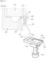
- FIG. 1 shows a conventional die coater 1 for applying an electrode slurry.
- the die coater 1 includes an upper block 2 and a lower block 3, and a shim 4 for a die coater is interposed between the upper block 2 and the lower block 3, and the upper block 2, the lower block 3, and the shim 4 are fastened and coupled to each other using a plurality of bolt members.
- the lower block 3 is provided with a manifold 5 for accommodating a predetermined volume of an electrode slurry, and the manifold 5 communicates with an external electrode slurry supply part (not shown).
- the present disclosure is directed to providing a die coater capable of effectively simultaneously coating a current collector for a secondary battery with two types of different liquids.
- One aspect of the present invention provides a die coater capable of effectively simultaneously coating a current collector for a secondary battery with two types of different liquids, which includes an upper block provided with a second liquid inlet, a lower block coupled to the upper block and provided with a manifold configured to accommodates a first liquid, and coater shims interposed between the upper block and the lower block to form a first slit and a second slit which are separated from each other, wherein the coater shims include a first coater shim which forms a first slit for discharging the first liquid accommodated in the manifold and a second coater shim which forms a second slit for discharging the second liquid supplied through the second liquid inlet, and the first coater shim and the second coater shim have the same height, do not overlap vertically, and are placed on the same surface between the upper block and the lower block.
- a width of the first slit may be by a width of the second coater shim.
- a height of the first slit may correspond to the height of the first coater shim, and a height of the second slit may be formed to be smaller than the height of the second coater shim.
- a distance between a pair of the other side walls of the second coater shim may correspond to the width of the first slit.
- a screw through-hole to access a bottom surface of the second coater shim may be formed in the lower block, and an end portion of a bolt screw-coupled to the screw through-hole may pressurize the second coater shim such that the second coater shim is in close contact with the upper block.
- the pressurizing block may pressurize portions of both side walls of the second coater shim.
- the die coater may further include a third coater shim which is provided with a concave U-shaped flow path groove which opens toward the upper block and has a bottom surface, in which a closed end of the U-shaped flow path groove is connected to the second liquid inlet of the upper block and two open ends of the U-shaped flow path groove form third slits, and which has a height that is equal to the height of each of the first and second coater shims, wherein the third coater shim may be disposed between the first and second guides.
- a third coater shim which is provided with a concave U-shaped flow path groove which opens toward the upper block and has a bottom surface, in which a closed end of the U-shaped flow path groove is connected to the second liquid inlet of the upper block and two open ends of the U-shaped flow path groove form third slits, and which has a height that is equal to the height of each of the first and second coater shims, wherein the third coater shim may be
- a screw through-hole to access to a bottom surface of the third coater shim may be formed in the lower block, and an end portion of a bolt screw-coupled to the screw through-hole may pressurize the third coater shim such that the third coater shim is in close contact with the upper block.
- An expanded pressurizing block hole may be formed at an end portion of the screw through-hole in a coupling direction, and a pressurizing block accommodated in the pressurizing block hole may be interposed between the bolt and the third coater shim to pressurize the third coater shim.
- the pressurizing block may pressurize portions of both side walls of the third coater shim.
- a second coater shim forming the second slit maintains airtightness using a separate pressurizing structure, internal mixing of the first liquid and the second liquid can be reliably prevented.
- a portion of a layer, a film, a region, a plate, or the like when a portion of a layer, a film, a region, a plate, or the like is described as being “on” another portion, this includes not only a case in which the portion is “directly on” another portion but also a case in which still another portion is present between the portion and another portion.
- a portion of a layer, a film, a region, a plate, or the like is described as being “under” another portion, this includes not only a case in which the portion is “directly under” another portion, but also a case in which still another portion is present between the portion and another portion.
- as being disposed “on” may include the case of being disposed not only on an upper portion but also on a lower portion.
- Embodiment of the present invention relates to a die coater capable of effectively simultaneously coating a current collector for a secondary battery with two types of different liquids.
- the die coater of an embodiment of the present invention includes an upper block provided with a second liquid inlet, a lower block coupled to the upper block and provided with a manifold which accommodates a first liquid, and coater shims interposed between the upper block and the lower block to form a first slit and a second slit which are separated from each other.
- the die coater of an embodiment of the present invention includes two types of the coater shims including a first coater shim and a second coater shim.
- the first coater shim forms the first slit which discharges the first liquid accommodated in the manifold of the lower block
- the second coater shim forms the second slit which discharges a second liquid supplied through a second liquid inlet of the upper block.
- the first coater shim and the second coater shim have the same height and do not vertically overlap, and thus the first and second coater shims are placed on the same surface between the upper block and the lower block.
- the die coater is formed to simultaneously discharge two different liquids, for example, an electrode slurry and an insulation coating liquid.
- two different liquids for example, an electrode slurry and an insulation coating liquid.
- embodiments of the present invention relates to a die coater 10 capable of effectively simultaneously coating a current collector for a secondary battery with two types of different liquids.
- the two types of different liquids may be, for example, an electrode slurry and an insulation coating liquid.
- the following description can be understood as an embodiment in which a first liquid is the electrode slurry and a second liquid is the insulation coating liquid.
- the die coater 10 of embodiments of the present invention includes an upper block 100, a lower block 200, and a coater shim 300 interposed therebetween.
- the coater shim 300 in an embodiment of the present invention includes a first coater shim 310 and a second coater shim 320.
- the upper block 100 is a part which includes a second liquid inlet 120 and occupies approximately half of a body of the die coater 10.
- the lower block 200 is a part which occupies the remaining half coupled to the upper block 100 and is provided with a manifold 210 which accommodates the first liquid.
- upper and lower portions are divided on the basis of the drawings and do not limit an actual installation direction of the die coater 10.
- FIG. 2 shows a first liquid inlet 110 that is formed in the upper block 100 communicating with the manifold 210 of the lower block 200, but the first liquid inlet 110 may be formed in the lower block 200.
- the second liquid inlet 120 should be formed in the upper block 100. This is because an arrangement design is limited due to a flow path groove 322 formed in the second coater shim 320 and its airtight structure, which will be described below.
- the coater shim 300 is interposed between the upper block 100 and the lower block 200.
- the coater shim 300 is basically interposed between the upper block 100 and the lower block 200 to form a slit with a height suitable for discharging a liquid.
- the coater shim 300 limits a flow direction of a liquid, which flows into the die coater 10 or is accommodated in the die coater 10, to be discharged toward the slit without a backflow and also serves to seal the liquid so as not to leak to other parts excluding the slit.
- the first coater shim 310 and the second coater shim 320 are included as the coater shim 300.
- the first coater shim 310 and the second coater shim 320 form a first slit 318 and a second slit 328 which are separated.
- the first coater shim 310 forms the first slit 318 which discharges the first liquid accommodated in the manifold 210 of the lower block 200
- the second coater shim 320 forms the second slit 328 which discharges the second liquid supplied through the second liquid inlet 120 of the upper block 100.
- first coater shim 310 and the second coater shim 320 have the same height and do not overlap vertically. Therefore, the first coater shim 310 and the second coater shim 320 are placed on the same surface between the upper block 100 and the lower block 200.
- FIG. 3 is a plan view illustrating the die coater 10 without the upper block 100
- FIG. 4 is an enlarged front view illustrating part "A" of FIG. 3
- the first coater shim 310 includes a base 312 extending in a width direction, and a first guide 314 and a second guide 316 which protrude to extend from both ends of the base 312.
- the second coater shim 320 is provided with a concave flow path groove 322 which opens toward the upper block 100 and has a bottom surface (see FIG. 5 ).
- a space between the first and second guides 314 and 316 forms the first slit 318
- an open end of the concave flow path groove 322 having the bottom surface forms the second slit 328. Since a depth of the flow path groove 322 is smaller than a thickness (height) of the second coater shim 320, as shown in FIG. 4 , a height of the first slit 318 corresponds to the height of the first coater shim 310, and a height of the second slit 328 is formed to be smaller than the height of the second coater shim 320.
- first coater shim 310 and the second coater shim 320 have the same height and are coplanar with each other without overlapping vertically, a width of the first slit 318 is limited by a width of the second coater shim 320.
- a pair of one side walls 324 of the second coater shims 320 are in close contact with inner walls of the first guide 314 and the second guide 316. Therefore, a distance between a pair of the other side walls 324 of the second coater shims 320, which face each other, (side surfaces opposite to sidewalls in close contact with each other) corresponds to an actual width of the first slit 318. That is, a length obtained by subtracting the width of the second coater shim 320 from the distance between the inner walls of the first guide 314 and the second guide 316 becomes the width of the first slit 318.
- the second coater shim 320 is structurally completely separated from the first liquid. Therefore, in the die coater 10 according to an embodiment of the present invention, a probability of mixing the two types of different liquids is significantly reduced.
- improved airtightness of the second coater shim 320 can be maintained by a pressurizing structure shown in FIG. 5 .
- the pressurizing structure of FIG. 5 is to reinforce the airtightness between the upper block 100 and the second coater shim 320. That is, since both side surfaces and the bottom surface of the first coater shim 310 are a closed structure securing the airtightness, the airtightness of the upper surface is affected by a degree of adhesion to the upper block 100. Accordingly, the pressurizing structure of FIG. 5 is applied to bring the second coater shim 320 more firmly in close contact with the upper block 100.
- a closed end of the concave flow path groove 322 formed in the second coater shim 320 is connected to the second liquid inlet 120 of the upper block 100 to receive the second liquid.
- the number and positions of second liquid inlets 120 correspond to the number and positions of second coater shims 320.
- the second embodiment corresponds to an embodiment suitable for simultaneously coating the current collector with an active material to have a structure of "insulation coating liquid - electrode slurry - insulation coating liquid" in two or more rows.
- FIG. 6 is an exploded perspective view illustrating a die coater 10 according to another embodiment of the present invention, and the second embodiment includes the entire structure of the first embodiment and further includes a third coater shim 330.
- the third coater shim 330 is installed in the middle of the die coater 10 in the width direction and discharges the second liquid in two streams through a U-shaped flow path groove 332. That is, the third coater shim 330 is formed to discharge the second liquid in two streams corresponding to both second coater shims 320 disposed in close contact with the first and second guides 314 and 316.
- die coater 100 upper block 110: first liquid inlet 120: second liquid inlet 130: pin member 200: lower block 210: manifold 220: pin insertion hole 230: screw through-hole 232: bolt 240: pressurizing block hole 242: pressurizing block 300: coater shim 310: first coater shim 312: base 314: first guide 316: second guide 318: first slit 320: second coater shim 322: flow path groove 324: sidewall 326: coupling hole 328: second slit 330: third coater shim 332: U-shaped flow path groove 334: sidewall 336: coupling hole 338: third slit
- the die coater of the present disclosure is useful for effectively and simultaneously coating the current collector for the secondary battery with two types of different liquids.
Landscapes
- Engineering & Computer Science (AREA)
- Manufacturing & Machinery (AREA)
- Chemical & Material Sciences (AREA)
- Chemical Kinetics & Catalysis (AREA)
- Electrochemistry (AREA)
- General Chemical & Material Sciences (AREA)
- Coating Apparatus (AREA)
Abstract
Description
- The present application is a national phase entry under 35 U.S.C §371 of International Application No.
PCT/KR2023/000366 filed on January 9, 2023 Korean Patent Application No. 10-2022-0004219 dated on January 11, 2022 - The present disclosure relates to a die coater capable of effectively simultaneously coating a current collector for a secondary battery with two types of different liquids.
- As the technology development and the demand for mobile devices increase, the demand for secondary batteries is also rapidly increasing. Among secondary batteries, lithium secondary batteries are widely used as energy sources for various electronic products as well as various mobile devices in terms of high energy density, a high operating voltage, and excellent storage and lifetime characteristics.
- A lithium secondary battery employs an electrode in which an active material layer and an insulating layer are formed on a surface of a current collector. The electrode is manufactured using a coating device such as a die coater such that both of an electrode slurry containing an active material and an insulation coating liquid containing an insulating material are applied onto the surface of the current collector to overlap a portion of a corner of an electrode mixture layer and then dried.
-
FIG. 1 shows a conventional die coater 1 for applying an electrode slurry. The die coater 1 includes anupper block 2 and alower block 3, and ashim 4 for a die coater is interposed between theupper block 2 and thelower block 3, and theupper block 2, thelower block 3, and theshim 4 are fastened and coupled to each other using a plurality of bolt members. Thelower block 3 is provided with amanifold 5 for accommodating a predetermined volume of an electrode slurry, and themanifold 5 communicates with an external electrode slurry supply part (not shown). - Here, the shim for a die coater serves to form a slit with an appropriate height between the upper block and the lower block and, simultaneously, to limit a flow direction of the electrode slurry to discharge the electrode slurry toward the slit and serves to seal between the upper block and the lower block to prevent the electrode slurry from leaking to other portions excluding the slit. The shim for a die coater is provided with guides protruding from both ends in a width direction, and a width of the electrode slurry applied onto the current collector depends on a distance between the guides.
- The insulation coating liquid is applied to both sides in the width direction of the electrode slurry applied onto the current collector in the width direction. Generally, after the electrode slurry is applied onto the current collector, the insulation coating liquid is applied through an additional process using a separate device. However, it is not desirable in terms of production efficiency to coat the current collector with the electrode slurry and the insulation coating liquid through separate processes.
- In order to overcome the above limitation, a technology for forming independent slits for discharging an electrode slurry and an insulation coating liquid in one die coater core has been introduced. However, when either one of the liquids of the two types of liquids leaks in the die coater, the two types of liquids (e.g., the electrode slurry and the insulation coating liquid) are mixed, or are mixed and discharged from an outlet of a slit, and thus a problem of causing a defect in quality of the current collector occurs.
- The present disclosure is directed to providing a die coater capable of effectively simultaneously coating a current collector for a secondary battery with two types of different liquids.
- However, the technical problems to be solved by the present invention are not limited to the above-described problem, and other problems not mentioned can be clearly understood by those skilled in the art from the following description of the present invention.
- One aspect of the present invention provides a die coater capable of effectively simultaneously coating a current collector for a secondary battery with two types of different liquids, which includes an upper block provided with a second liquid inlet, a lower block coupled to the upper block and provided with a manifold configured to accommodates a first liquid, and coater shims interposed between the upper block and the lower block to form a first slit and a second slit which are separated from each other, wherein the coater shims include a first coater shim which forms a first slit for discharging the first liquid accommodated in the manifold and a second coater shim which forms a second slit for discharging the second liquid supplied through the second liquid inlet, and the first coater shim and the second coater shim have the same height, do not overlap vertically, and are placed on the same surface between the upper block and the lower block.
- A width of the first slit may be by a width of the second coater shim.
- A height of the first slit may correspond to the height of the first coater shim, and a height of the second slit may be formed to be smaller than the height of the second coater shim.
- The second coater shim may be provided with a concave flow path groove which opens toward the upper block and has a bottom surface, a closed end of the flow path groove may be connected to the second liquid inlet of the upper block, and an open end of the flow path groove may form the second slit.
- The first coater shim may include a base extending in a width direction and first and second guides extending to protrude from both ends of the base, and a side walls of the second coater shim may be in close contact with inner walls of the first and second guides.
- A distance between a pair of the other side walls of the second coater shim may correspond to the width of the first slit.
- A screw through-hole to access a bottom surface of the second coater shim may be formed in the lower block, and an end portion of a bolt screw-coupled to the screw through-hole may pressurize the second coater shim such that the second coater shim is in close contact with the upper block.
- An expanded pressurizing block hole may be formed at an end portion of the screw through-hole in a coupling direction, and a pressurizing block accommodated in the pressurizing block hole may be interposed between the bolt and the second coater shim to pressurize the second coater shim.
- The pressurizing block may pressurize portions of both side walls of the second coater shim.
- The die coater may further include a third coater shim which is provided with a concave U-shaped flow path groove which opens toward the upper block and has a bottom surface, in which a closed end of the U-shaped flow path groove is connected to the second liquid inlet of the upper block and two open ends of the U-shaped flow path groove form third slits, and which has a height that is equal to the height of each of the first and second coater shims, wherein the third coater shim may be disposed between the first and second guides.
- A screw through-hole to access to a bottom surface of the third coater shim may be formed in the lower block, and an end portion of a bolt screw-coupled to the screw through-hole may pressurize the third coater shim such that the third coater shim is in close contact with the upper block.
- An expanded pressurizing block hole may be formed at an end portion of the screw through-hole in a coupling direction, and a pressurizing block accommodated in the pressurizing block hole may be interposed between the bolt and the third coater shim to pressurize the third coater shim.
- The pressurizing block may pressurize portions of both side walls of the third coater shim.
- In accordance with a die coater of the present disclosure, the die coater is formed to simultaneously discharge two different liquids, for example, an electrode slurry and an insulation coating liquid. In particular, a first slit and a second slit, which discharge the first liquid and the second liquid, respectively, can be physically separated from each other in the die coater.
- In addition, since a second coater shim forming the second slit maintains airtightness using a separate pressurizing structure, internal mixing of the first liquid and the second liquid can be reliably prevented.
- Therefore, in accordance with the die coater of the present disclosure, it is possible to effectively simultaneously coat a current collector with two types of different liquids.
- It should be noted that effects of the present invention are not limited to the above described effect, and other effects of the present invention not mentioned above can be clearly understood by those skilled in the art from the following detailed description.
- However, the following drawings attached to the present specification illustrate exemplary embodiments of the present invention and serve to further assist understanding of the technical idea of the present invention together with the detailed description of the present invention, which will be described below, and thus the present invention should not be construed as being limited to details shown in the accompanying drawings.
-
FIG. 1 is a diagram illustrating a configuration of a die coater according to the related art. -
FIG. 2 is an exploded perspective view illustrating a die coater according to one embodiment of the present invention. -
FIG. 3 is a plan view illustrating the die coater through an upper block. -
FIG. 4 is an enlarged front view illustrating part "A" ofFIG. 3 . -
FIG. 5 is an enlarged front view illustrating part "B" ofFIG. 3 . -
FIG. 6 is an exploded perspective view illustrating a die coater according to another embodiment of the present invention. -
FIG. 7 is a perspective view illustrating a third coater shim included in the die coater ofFIG. 6 . - The present invention may be modified into various forms and may have a variety of embodiments, and, therefore, specific embodiments will be described in detail below.
- However, the embodiments are not to be taken in a sense which limits the present invention to the specific embodiments and should be construed to include all modifications, equivalents, or substituents falling within the spirit and technical scope of the present invention.
- In the present invention, the terms "comprising," "having," and the like are used to specify the presence of a feature, a number, a step, an operation, a component, an element, or a combination thereof described herein, and they do not preclude the presence or addition of one or more other features, numbers, steps, operations, components, elements, or combinations thereof.
- In addition, in the present invention, when a portion of a layer, a film, a region, a plate, or the like is described as being "on" another portion, this includes not only a case in which the portion is "directly on" another portion but also a case in which still another portion is present between the portion and another portion. Conversely, when a portion of a layer, a film, a region, a plate, or the like is described as being "under" another portion, this includes not only a case in which the portion is "directly under" another portion, but also a case in which still another portion is present between the portion and another portion. In addition, in the present application, as being disposed "on" may include the case of being disposed not only on an upper portion but also on a lower portion.
- Embodiment of the present invention relates to a die coater capable of effectively simultaneously coating a current collector for a secondary battery with two types of different liquids.
- In one example, the die coater of an embodiment of the present invention includes an upper block provided with a second liquid inlet, a lower block coupled to the upper block and provided with a manifold which accommodates a first liquid, and coater shims interposed between the upper block and the lower block to form a first slit and a second slit which are separated from each other.
- Here, the die coater of an embodiment of the present invention includes two types of the coater shims including a first coater shim and a second coater shim. The first coater shim forms the first slit which discharges the first liquid accommodated in the manifold of the lower block, and the second coater shim forms the second slit which discharges a second liquid supplied through a second liquid inlet of the upper block. In particular, the first coater shim and the second coater shim have the same height and do not vertically overlap, and thus the first and second coater shims are placed on the same surface between the upper block and the lower block.
- According to the die coater of an embodiment of the present invention, the die coater is formed to simultaneously discharge two different liquids, for example, an electrode slurry and an insulation coating liquid. In particular, since the first slit and the second slit, which discharge the first liquid and the second liquid, respectively, are physically separated from each other in the die coater, an internal mixing of the first liquid and the second liquid can be prevented.
- Hereinafter, some embodiments of a die coater according to the present invention will be described in detail with reference to the accompanying drawings.
-
FIG. 2 is an exploded perspective view illustrating adie coater 10 according to one embodiment of the present invention. Referring toFIG. 2 , the overall configuration of thedie coater 10 according to an embodiment of the present invention will be described as follows. - As described above, embodiments of the present invention relates to a
die coater 10 capable of effectively simultaneously coating a current collector for a secondary battery with two types of different liquids. The two types of different liquids may be, for example, an electrode slurry and an insulation coating liquid. The following description can be understood as an embodiment in which a first liquid is the electrode slurry and a second liquid is the insulation coating liquid. - The
die coater 10 of embodiments of the present invention includes anupper block 100, alower block 200, and acoater shim 300 interposed therebetween. In particular, thecoater shim 300 in an embodiment of the present invention includes afirst coater shim 310 and asecond coater shim 320. - The
upper block 100 is a part which includes a secondliquid inlet 120 and occupies approximately half of a body of thedie coater 10. Thelower block 200 is a part which occupies the remaining half coupled to theupper block 100 and is provided with a manifold 210 which accommodates the first liquid. Here, upper and lower portions are divided on the basis of the drawings and do not limit an actual installation direction of thedie coater 10. - For reference,
FIG. 2 shows a firstliquid inlet 110 that is formed in theupper block 100 communicating with themanifold 210 of thelower block 200, but the firstliquid inlet 110 may be formed in thelower block 200. On the other hand, the secondliquid inlet 120 should be formed in theupper block 100. This is because an arrangement design is limited due to a flow path groove 322 formed in thesecond coater shim 320 and its airtight structure, which will be described below. - The
coater shim 300 is interposed between theupper block 100 and thelower block 200. Thecoater shim 300 is basically interposed between theupper block 100 and thelower block 200 to form a slit with a height suitable for discharging a liquid. In addition, thecoater shim 300 limits a flow direction of a liquid, which flows into thedie coater 10 or is accommodated in thedie coater 10, to be discharged toward the slit without a backflow and also serves to seal the liquid so as not to leak to other parts excluding the slit. - In an embodiment of the present invention, the
first coater shim 310 and thesecond coater shim 320 are included as thecoater shim 300. Thefirst coater shim 310 and thesecond coater shim 320 form afirst slit 318 and asecond slit 328 which are separated. Specifically, thefirst coater shim 310 forms thefirst slit 318 which discharges the first liquid accommodated in themanifold 210 of thelower block 200, and thesecond coater shim 320 forms thesecond slit 328 which discharges the second liquid supplied through the secondliquid inlet 120 of theupper block 100. - In addition, the
first coater shim 310 and thesecond coater shim 320 have the same height and do not overlap vertically. Therefore, thefirst coater shim 310 and thesecond coater shim 320 are placed on the same surface between theupper block 100 and thelower block 200. -
FIG. 3 is a plan view illustrating thedie coater 10 without theupper block 100, andFIG. 4 is an enlarged front view illustrating part "A" ofFIG. 3 . Referring toFIGS. 3 and 4 , thefirst coater shim 310 includes a base 312 extending in a width direction, and afirst guide 314 and asecond guide 316 which protrude to extend from both ends of thebase 312. In addition, thesecond coater shim 320 is provided with a concave flow path groove 322 which opens toward theupper block 100 and has a bottom surface (seeFIG. 5 ). - Here, in the
first coater shim 310, a space between the first andsecond guides first slit 318, and in thesecond coater shim 320, an open end of the concave flow path groove 322 having the bottom surface forms thesecond slit 328. Since a depth of the flow path groove 322 is smaller than a thickness (height) of thesecond coater shim 320, as shown inFIG. 4 , a height of thefirst slit 318 corresponds to the height of thefirst coater shim 310, and a height of thesecond slit 328 is formed to be smaller than the height of thesecond coater shim 320. - In addition, since the
first coater shim 310 and thesecond coater shim 320 have the same height and are coplanar with each other without overlapping vertically, a width of thefirst slit 318 is limited by a width of thesecond coater shim 320. - For example, in the first embodiment shown in
FIG. 3 , a pair of oneside walls 324 of the second coater shims 320 are in close contact with inner walls of thefirst guide 314 and thesecond guide 316. Therefore, a distance between a pair of theother side walls 324 of the second coater shims 320, which face each other, (side surfaces opposite to sidewalls in close contact with each other) corresponds to an actual width of thefirst slit 318. That is, a length obtained by subtracting the width of thesecond coater shim 320 from the distance between the inner walls of thefirst guide 314 and thesecond guide 316 becomes the width of thefirst slit 318. - As described above, looking at a structure of the
second slit 328 formed by thesecond coater shim 320, since the first liquid of thefirst slit 318 is blocked by the bothside walls 324 of thesecond coater shim 320, and a lower side of the flow path groove 322 is the bottom surface and an upper side thereof is in close contact with theupper block 100, thesecond coater shim 320 is structurally completely separated from the first liquid. Therefore, in thedie coater 10 according to an embodiment of the present invention, a probability of mixing the two types of different liquids is significantly reduced. - In addition, according to an embodiment of the present invention, improved airtightness of the
second coater shim 320 can be maintained by a pressurizing structure shown inFIG. 5 . The pressurizing structure ofFIG. 5 is to reinforce the airtightness between theupper block 100 and thesecond coater shim 320. That is, since both side surfaces and the bottom surface of thefirst coater shim 310 are a closed structure securing the airtightness, the airtightness of the upper surface is affected by a degree of adhesion to theupper block 100. Accordingly, the pressurizing structure ofFIG. 5 is applied to bring thesecond coater shim 320 more firmly in close contact with theupper block 100. - Referring to
FIG. 5 , a closed end of the concave flow path groove 322 formed in thesecond coater shim 320 is connected to the secondliquid inlet 120 of theupper block 100 to receive the second liquid. For reference, as shown inFIG. 2 , the number and positions of secondliquid inlets 120 correspond to the number and positions of second coater shims 320. - In addition, in the illustrated embodiment, an installation position of the
second coater shim 320 is accurately set by apin member 130 provided in theupper block 100. Thepin member 130 protrudes from near the secondliquid inlet 120 and is inserted into acoupling hole 326 provided in thesecond coater shim 320 so that the position of thesecond coater shim 320 is fixed. - Here, the
pin member 130 and thecoupling hole 326 may be designed such that a fixing position and a direction of thesecond coater shim 320 are consistently determined. Specifically, an installation direction should be consistently determined so that thesecond coater shim 320 receiving the insertedpin member 130 is prevented from being rotated. This may be achieved through design of a structure providing a plurality ofpin members 130, a structure forming thepin member 130 and thecoupling hole 326 in shapes excluding a circular cross section, or combining these structures. In addition, if necessary, a concavepin insertion hole 220 for accommodating theprotruding pin member 130 may be provided in thelower block 200. - A screw through-
hole 230 to access to the bottom surface of thesecond coater shim 320 is formed in thelower block 200, and an end portion of abolt 232 screw-coupled to the screw through-hole 230 presses thesecond coater shim 320 so that the upper surface of thesecond coater shim 320 is more strongly pressed against theupper block 100. - In addition, in order to more effectively press the
second coater shim 320 to theupper block 100, an expandedpressurizing block hole 240 is formed at an end portion of the screw through-hole 230 in a coupling direction of the screw through-hole 230 (a direction in which the bolt is tightened), and apressurizing block 242 accommodated in the pressurizingblock hole 240 is interposed between thebolt 232 and thesecond coater shim 320, and thus thesecond coater shim 320 can be pressurized more efficiently. For example, the pressurizingblock 242 pressurizes portions of the bothside walls 324 of thesecond coater shim 320, and thus thesecond coater shim 320 can be pressurized more efficiently. - In addition to the pressurizing structure prepared separately from the
second coater shim 320, that is, the pressurizing force generated by mutual engagement of theupper block 100 and thelower block 200, due to an additional pressurizing force by which thebolt 232 pressurizes thesecond coater shim 320, a probability that the second liquid flowing through thesecond coater shim 320 is mixed with the first liquid around the second liquid becomes extremely low. - The second embodiment of the present invention is an embodiment suitable for a case in which a first liquid and a second liquid, for example, an electrode slurry and an insulation coating liquid, are applied onto a current collector provided in the form of a coil in two or more rows, and then a slitting process is performed.
- That is, the second embodiment corresponds to an embodiment suitable for simultaneously coating the current collector with an active material to have a structure of "insulation coating liquid - electrode slurry - insulation coating liquid" in two or more rows.
-
FIG. 6 is an exploded perspective view illustrating adie coater 10 according to another embodiment of the present invention, and the second embodiment includes the entire structure of the first embodiment and further includes athird coater shim 330. Thethird coater shim 330 is installed in the middle of thedie coater 10 in the width direction and discharges the second liquid in two streams through a U-shapedflow path groove 332. That is, thethird coater shim 330 is formed to discharge the second liquid in two streams corresponding to both second coater shims 320 disposed in close contact with the first andsecond guides - In addition, the
third coater shim 330 is disposed between the first andsecond guides first coater shim 310. As thesecond coater shim 320 limits the actual width of thefirst slit 318, thethird coater shim 330 also serves as a factor for limiting thefirst slit 318. Therefore, thethird coater shim 330 disposed in the middle of thefirst slit 318 divides the first liquid into two liquids to discharge the first liquid in two rows in parallel. A height of thethird coater shim 330 corresponds to the heights of the first and second coater shims 310 and 320. - Due to the arrangement of the
third coater shim 330 and the two-row discharge structure of the second liquid, the coating structure of "second liquid - first liquid - second liquid" is formed on the current collector in two rows in parallel in a length direction of the current collector, and two current collector rolls may be obtained by performing a slitting process by which a portion between the two rows in parallel is cut. -
FIG. 7 is a perspective view illustrating thethird coater shim 330 which has the same configuration as thesecond coater shim 320 except for the structure of the U-shapedflow path groove 332. Specifically, thethird coater shim 330 is provided with the concave U-shaped flow path groove 332 which opens toward theupper block 100 and has a bottom surface. A closed end of the U-shaped flow path groove 332 is connected to the secondliquid inlet 120 of theupper block 100, and two open ends of the U-shaped flow path groove 332 form third slits 338. Similarly, acoupling hole 336 is inserted into apin member 130 so that a position of thethird coater shim 330 is fixed and does not rotate. - Also, the same pressurizing structure as the
second coater shim 320 may be applied onto thethird coater shim 330, and a configuration and operation of thethird coater shim 330 are the same as those described above. That is, a screw through-hole 230 to access to the bottom surface of thesecond coater shim 320 is formed in thelower block 200, and an end portion of abolt 232 screw-coupled to the screw through-hole 230 pressurizes thethird coater shim 330 such that thethird coater shim 330 is in close contact with theupper block 100. - In addition, an expanded
pressurizing block hole 240 is formed at an end portion of the screw through-hole 230 in a coupling direction, and apressurizing block 242 accommodated in the pressurizingblock hole 240 is interposed between thebolt 232 and thethird coater shim 330, and thus thethird coater shim 330 can be pressurized, for example, the pressurizingblock 242 can pressurize portions ofside walls 334 of thethird coater shim 330. - Here, in the second embodiment, although it is described that the first liquid and the second liquid are simultaneously applied onto the electrode part in two rows in parallel by adding one
third coater shim 330, it can be obviously understood by those skilled in the art that two or more third coater shims 330 may be added and thus the first liquid and the second liquid may be applied in three or more rows. - As described above, the present invention has been described in more detail with reference to the accompanying drawings and the embodiments. Therefore, the configurations described herein or shown in the drawings are merely one embodiment of the present invention and do not represent all the technical spirit of the present invention such that it should be understood that there may be various equivalents and modifications capable of substituting the embodiments and the configurations at the time of filing the present application.
-
10: die coater 100: upper block 110: first liquid inlet 120: second liquid inlet 130: pin member 200: lower block 210: manifold 220: pin insertion hole 230: screw through-hole 232: bolt 240: pressurizing block hole 242: pressurizing block 300: coater shim 310: first coater shim 312: base 314: first guide 316: second guide 318: first slit 320: second coater shim 322: flow path groove 324: sidewall 326: coupling hole 328: second slit 330: third coater shim 332: U-shaped flow path groove 334: sidewall 336: coupling hole 338: third slit - The die coater of the present disclosure is useful for effectively and simultaneously coating the current collector for the secondary battery with two types of different liquids.
Claims (13)
- A die coater comprising:an upper block having a plurality of second liquid inlets;a lower block coupled to the upper block, wherein the lower block includes a manifold configured to accommodate a first liquid; anda plurality of coater shims interposed between the upper block and the lower block to form a first slit and a second slit, wherein the first slit and the second slit are spaced apart from each other,wherein the plurality of coater shims include a first coater shim and a second coater shim, wherein the first coater shim includes the first slit configured to discharge the first liquid accommodated in the manifold and the second coater shim includes the second slit configured to discharge a second liquid supplied through an at least one of the plurality of second liquid inlets, andwherein the first coater shim and the second coater shim have a same height, do not overlap vertically, and are disposed on a same surface between the upper block and the lower block.
- The die coater of claim 1, wherein a width of the first slit is determined by a width of the second coater shim.
- The die coater of claim 2, wherein:a height of the first slit is the same as the height of the first coater shim; anda height of the second slit is smaller than the height of the second coater shim.
- The die coater of claim 3, wherein:
the second coater shim includes:a recessed concave flow path groove disposed to face the upper block and has a bottom surface;a closed end of the recessed concave flow path groove being connected to the at least one of the plurality of the second liquid inlets of the upper block; andan open end of the recessed concave flow path groove that forms the second slit. - The die coater of claim 4, wherein:the first coater shim includes a base extending in a width direction and first and second guides protruding from both ends of the base, wherein the first guide and the second guide extend perpendicular to the width direction of the base; anda pair of first side walls of the second coater shim contact an inner wall of each of the first and second guides,wherein the pair of the first side walls of the second coater shim are disposed to face an exterior region of the die coater in the width direction, andwherein the inner wall of each of the first and second guides is disposed to face a central region of the die coater in the width direction.
- The die coater of claim 5, wherein a distance between a pair of second side walls of the second coater shim determines a width of the first slit, wherein the pair of second sidewalls of the second coater shim are disposed to face the central region of the die coater shim in the width direction;
wherein the pair of second sidewalls of the second coater shim are disposed closer to the central region than the inner walls of each of the first and second guides. - The die coater of claim 1, wherein:a screw through-hole is disposed in the lower block, so at to provide access to a bottom surface of the second coater shim; andan end portion of a bolt screw coupled to the screw through-hole is configured to pressurize the second coater shim, so as to bring the second coater shim in close contact with the upper block.
- The die coater of claim 7, wherein:an expanded pressurizing block hole is disposed at an end portion of the screw through-hole in a coupling direction, wherein the coupling direction is perpendicular to the width direction of the base; anda pressurizing block accommodated in the expanded pressurizing block hole is interposed between the bolt and the second coater shim, wherein the pressurizing block is configured to pressurize the second coater shim.
- The die coater of claim 8, wherein the pressurizing block is configured to pressurize portions of both side walls of the second coater shim.
- The die coater of claim 5, further comprising:a third coater shim disposed between each of the each of the first and second guides,wherein the third coater shim includes:a recessed concave U-shaped flow path groove disposed to face the upper block and has a bottom surface,a closed end of the recessed U-shaped flow path groove being connected to the at least one of the second liquid inlets of the upper block,two open ends of the recessed U-shaped flow path groove form third slits, andwherein the third coater shim has a height that is equal to the height of each of the first and second coater shims,
- The die coater of claim 10, wherein:a screw through-hole is disposed in the lower block, so as to provide to access to a bottom surface of the third coater shim; andan end portion of a bolt screw-coupled to the screw through-hole is configured to pressurize the third coater shim, so as to bring the third coater shim in close contact with the upper block.
- The die coater of claim 11, wherein:an expanded pressurizing block hole is disposed at an end portion of the screw through-hole in a coupling direction, wherein the coupling direction is perpendicular to the width direction of the base; anda pressurizing block accommodated in the expanded pressurizing block hole is interposed between the bolt and the third coater shim, wherein the pressurizing block is configured to pressurize the third coater shim.
- The die coater of claim 12, wherein the pressurizing block is configured to pressurizes portions of both side walls of the third coater shim.
Applications Claiming Priority (2)
| Application Number | Priority Date | Filing Date | Title |
|---|---|---|---|
| KR1020220004219A KR102876795B1 (en) | 2022-01-11 | 2022-01-11 | Die coater for coating of electrode slurry on secondary cell electrode |
| PCT/KR2023/000366 WO2023136567A1 (en) | 2022-01-11 | 2023-01-09 | Die coater for coating secondary battery current collector with active material |
Publications (3)
| Publication Number | Publication Date |
|---|---|
| EP4289518A1 true EP4289518A1 (en) | 2023-12-13 |
| EP4289518A4 EP4289518A4 (en) | 2024-11-06 |
| EP4289518B1 EP4289518B1 (en) | 2026-03-18 |
Family
ID=87279343
Family Applications (1)
| Application Number | Title | Priority Date | Filing Date |
|---|---|---|---|
| EP23740411.6A Active EP4289518B1 (en) | 2022-01-11 | 2023-01-09 | Die coater for coating current collector of secondary battery with active material |
Country Status (6)
| Country | Link |
|---|---|
| US (1) | US20240058834A1 (en) |
| EP (1) | EP4289518B1 (en) |
| JP (1) | JP7640179B2 (en) |
| KR (1) | KR102876795B1 (en) |
| CN (1) | CN116783005A (en) |
| WO (1) | WO2023136567A1 (en) |
Families Citing this family (11)
| Publication number | Priority date | Publication date | Assignee | Title |
|---|---|---|---|---|
| KR20220059744A (en) * | 2020-11-03 | 2022-05-10 | 주식회사 엘지에너지솔루션 | Shim for die coater, die coater including the same, and lithium secondary battery including a positive electrode manufactured using the same |
| KR20240068385A (en) * | 2022-11-10 | 2024-05-17 | 에스케이온 주식회사 | Electrode coating device |
| CN120418966A (en) * | 2023-09-05 | 2025-08-01 | 株式会社Lg新能源 | Method for manufacturing positive electrode, and lithium secondary battery comprising same |
| JP2026508539A (en) * | 2023-12-05 | 2026-03-11 | エルジー エナジー ソリューション リミテッド | Die coater, coating equipment including same, and electrode coating method using same |
| KR20250146660A (en) * | 2024-04-02 | 2025-10-13 | 주식회사 엘지에너지솔루션 | Coating apparatus |
| KR20250148201A (en) * | 2024-04-05 | 2025-10-14 | 주식회사 엘지에너지솔루션 | Slot die coater for electrode and manufacturing method of electrode using the same |
| KR20250152849A (en) * | 2024-04-17 | 2025-10-24 | 주식회사 엘지에너지솔루션 | Die coater |
| KR20250155231A (en) * | 2024-04-23 | 2025-10-30 | 주식회사 엘지에너지솔루션 | Liquid insulator flow passage structure of slot die coater |
| KR20250168808A (en) * | 2024-05-24 | 2025-12-02 | 주식회사 엘지에너지솔루션 | Coating apparatus and apparatus of manufacturing electrode including the same |
| KR20260011943A (en) | 2024-07-17 | 2026-01-26 | 주식회사 엘지에너지솔루션 | Coating apparatus |
| WO2026054522A1 (en) * | 2024-09-06 | 2026-03-12 | 주식회사 엘지에너지솔루션 | Coating device |
Family Cites Families (19)
| Publication number | Priority date | Publication date | Assignee | Title |
|---|---|---|---|---|
| KR101125649B1 (en) * | 2010-05-24 | 2012-03-27 | 삼성에스디아이 주식회사 | Active material coating apparatus and coating method using the same |
| JP6330414B2 (en) * | 2014-03-27 | 2018-05-30 | 日本電気株式会社 | Coating head, coating apparatus and coating method |
| JP6539069B2 (en) * | 2015-03-09 | 2019-07-03 | 東レエンジニアリング株式会社 | Coating device |
| CN205253457U (en) | 2015-12-31 | 2016-05-25 | 芜湖天弋能源科技有限公司 | Coating apparatus |
| KR102134587B1 (en) * | 2016-02-12 | 2020-07-16 | 주식회사 엘지화학 | Electrode Coating Apparatus Capable of Simultaneously Coating Different Substances Constituting Electrode for Secondary Battery |
| CN206304983U (en) * | 2016-11-21 | 2017-07-07 | 宁德新能源科技有限公司 | Extrusion coated pad and extrusion coated die head |
| EP3609625B1 (en) * | 2017-04-10 | 2025-07-02 | Roche Diabetes Care GmbH | Slot die apparatus and method for applying a plurality of wet films to a substrate using said appratus |
| CN108816565A (en) | 2018-06-28 | 2018-11-16 | 合肥国轩高科动力能源有限公司 | Anti-mixing dispensing ceramic coating device and method |
| JP7155881B2 (en) * | 2018-10-31 | 2022-10-19 | トヨタ自動車株式会社 | Electrode plate, battery using same, method for manufacturing electrode plate, method for manufacturing battery using same, die head |
| CN210138795U (en) * | 2019-03-20 | 2020-03-13 | 多氟多新能源科技有限公司 | A gasket for extrusion die |
| CN209709083U (en) * | 2019-04-03 | 2019-11-29 | 力神电池(苏州)有限公司 | A kind of Novel gasket for lithium battery pole slice coating slurry |
| KR102035826B1 (en) * | 2019-05-31 | 2019-10-24 | 씨아이에스(주) | Multi-row simultaneous coating slot die |
| WO2020248162A1 (en) | 2019-06-12 | 2020-12-17 | 林明德 | Portable cup and cover structure thereof |
| JP7368125B2 (en) | 2019-07-05 | 2023-10-24 | 株式会社Aescジャパン | Coating device and method for manufacturing electrodes for batteries |
| KR20210083512A (en) | 2019-12-27 | 2021-07-07 | 주식회사 엘지에너지솔루션 | Electrode slurry coating shim with excellent coating uniformity and coating die comprising the same |
| CN212113924U (en) * | 2020-05-22 | 2020-12-08 | 孚能科技(赣州)股份有限公司 | Gasket and slit coater |
| KR102798646B1 (en) * | 2020-06-17 | 2025-04-23 | 주식회사 엘지에너지솔루션 | Slot die comprising protrusions and notches and electrode slurry coating device comprising the same |
| CN213133858U (en) * | 2020-07-02 | 2021-05-07 | 欣旺达电动汽车电池有限公司 | Coated gasket |
| CN213612390U (en) * | 2020-09-30 | 2021-07-06 | 蜂巢能源科技有限公司 | Die head gasket and coating machine for material coating |
-
2022
- 2022-01-11 KR KR1020220004219A patent/KR102876795B1/en active Active
-
2023
- 2023-01-09 CN CN202380009774.8A patent/CN116783005A/en active Pending
- 2023-01-09 US US18/275,845 patent/US20240058834A1/en active Pending
- 2023-01-09 EP EP23740411.6A patent/EP4289518B1/en active Active
- 2023-01-09 JP JP2023546519A patent/JP7640179B2/en active Active
- 2023-01-09 WO PCT/KR2023/000366 patent/WO2023136567A1/en not_active Ceased
Also Published As
| Publication number | Publication date |
|---|---|
| US20240058834A1 (en) | 2024-02-22 |
| EP4289518B1 (en) | 2026-03-18 |
| JP7640179B2 (en) | 2025-03-05 |
| KR20230108603A (en) | 2023-07-18 |
| WO2023136567A1 (en) | 2023-07-20 |
| JP2024506147A (en) | 2024-02-09 |
| CN116783005A (en) | 2023-09-19 |
| EP4289518A4 (en) | 2024-11-06 |
| KR102876795B1 (en) | 2025-10-24 |
Similar Documents
| Publication | Publication Date | Title |
|---|---|---|
| EP4289518A1 (en) | Die coater for coating secondary battery current collector with active material | |
| EP4243109B1 (en) | Die coater shim and die coater for coating active material on current collector for secondary battery | |
| EP4292718A1 (en) | Die coater for coating active material of secondary battery current collector | |
| EP4353365A1 (en) | Die coater for coating active material of secondary battery current collector | |
| EP4321264B1 (en) | Die coater capable of multi-layer coating of active materials | |
| EP3715753B1 (en) | Refrigerator box body and refrigerator | |
| US12087985B2 (en) | Fuel cell stack and method of producing fuel cell stack | |
| KR100877755B1 (en) | Control Valve Type Lead Acid Battery | |
| US20250105243A1 (en) | Die Coater for Coating Electrode Slurry and Insulating Liquid | |
| US10230126B2 (en) | Fuel cell stack assembly | |
| KR20240068385A (en) | Electrode coating device | |
| US11387467B2 (en) | Fuel cell separator member and fuel cell stack | |
| US12573642B2 (en) | Separator for fuel cell and separator assembly and fuel cell stack including the same | |
| EP4663307A1 (en) | Die coater, coating equipment comprising same, and method for coating electrode using same | |
| JP2018006155A (en) | Fuel cell stack | |
| KR20240048546A (en) | active gas generation device | |
| CN120712149A (en) | Slot die coater | |
| JPH07249427A (en) | Fuel cell |
Legal Events
| Date | Code | Title | Description |
|---|---|---|---|
| STAA | Information on the status of an ep patent application or granted ep patent |
Free format text: STATUS: THE INTERNATIONAL PUBLICATION HAS BEEN MADE |
|
| PUAI | Public reference made under article 153(3) epc to a published international application that has entered the european phase |
Free format text: ORIGINAL CODE: 0009012 |
|
| STAA | Information on the status of an ep patent application or granted ep patent |
Free format text: STATUS: REQUEST FOR EXAMINATION WAS MADE |
|
| 17P | Request for examination filed |
Effective date: 20230831 |
|
| AK | Designated contracting states |
Kind code of ref document: A1 Designated state(s): AL AT BE BG CH CY CZ DE DK EE ES FI FR GB GR HR HU IE IS IT LI LT LU LV MC ME MK MT NL NO PL PT RO RS SE SI SK SM TR |
|
| A4 | Supplementary search report drawn up and despatched |
Effective date: 20241008 |
|
| RIC1 | Information provided on ipc code assigned before grant |
Ipc: H01M 10/42 20060101ALI20241001BHEP Ipc: H01M 4/04 20060101ALI20241001BHEP Ipc: B05C 5/02 20060101AFI20241001BHEP |
|
| DAV | Request for validation of the european patent (deleted) | ||
| DAX | Request for extension of the european patent (deleted) | ||
| STAA | Information on the status of an ep patent application or granted ep patent |
Free format text: STATUS: EXAMINATION IS IN PROGRESS |
|
| 17Q | First examination report despatched |
Effective date: 20250526 |
|
| GRAP | Despatch of communication of intention to grant a patent |
Free format text: ORIGINAL CODE: EPIDOSNIGR1 |
|
| STAA | Information on the status of an ep patent application or granted ep patent |
Free format text: STATUS: GRANT OF PATENT IS INTENDED |
|
| INTG | Intention to grant announced |
Effective date: 20251118 |
|
| P01 | Opt-out of the competence of the unified patent court (upc) registered |
Free format text: CASE NUMBER: UPC_APP_0015364_4289518/2025 Effective date: 20251201 |
|
| GRAS | Grant fee paid |
Free format text: ORIGINAL CODE: EPIDOSNIGR3 |
|
| GRAA | (expected) grant |
Free format text: ORIGINAL CODE: 0009210 |
|
| STAA | Information on the status of an ep patent application or granted ep patent |
Free format text: STATUS: THE PATENT HAS BEEN GRANTED |
|
| AK | Designated contracting states |
Kind code of ref document: B1 Designated state(s): AL AT BE BG CH CY CZ DE DK EE ES FI FR GB GR HR HU IE IS IT LI LT LU LV MC ME MK MT NL NO PL PT RO RS SE SI SK SM TR |
|
| REG | Reference to a national code |
Ref country code: CH Ref legal event code: F10 Free format text: ST27 STATUS EVENT CODE: U-0-0-F10-F00 (AS PROVIDED BY THE NATIONAL OFFICE) Effective date: 20260318 Ref country code: GB Ref legal event code: FG4D |
|
| REG | Reference to a national code |
Ref country code: DE Ref legal event code: R096 Ref document number: 602023013799 Country of ref document: DE |
|
| REG | Reference to a national code |
Ref country code: IE Ref legal event code: FG4D |