EP4289463A1 - Catheter - Google Patents
Catheter Download PDFInfo
- Publication number
- EP4289463A1 EP4289463A1 EP21924773.1A EP21924773A EP4289463A1 EP 4289463 A1 EP4289463 A1 EP 4289463A1 EP 21924773 A EP21924773 A EP 21924773A EP 4289463 A1 EP4289463 A1 EP 4289463A1
- Authority
- EP
- European Patent Office
- Prior art keywords
- lumen
- notch
- shaft
- distal end
- wire
- Prior art date
- Legal status (The legal status is an assumption and is not a legal conclusion. Google has not performed a legal analysis and makes no representation as to the accuracy of the status listed.)
- Pending
Links
- 230000002093 peripheral effect Effects 0.000 claims description 12
- 230000035515 penetration Effects 0.000 description 77
- 210000001519 tissue Anatomy 0.000 description 36
- 238000000034 method Methods 0.000 description 30
- 238000003384 imaging method Methods 0.000 description 28
- 239000003550 marker Substances 0.000 description 16
- 230000000694 effects Effects 0.000 description 15
- 229920005989 resin Polymers 0.000 description 13
- 239000011347 resin Substances 0.000 description 13
- 239000000463 material Substances 0.000 description 12
- 238000007789 sealing Methods 0.000 description 11
- 210000004351 coronary vessel Anatomy 0.000 description 10
- 210000004204 blood vessel Anatomy 0.000 description 8
- 238000010586 diagram Methods 0.000 description 7
- 230000004048 modification Effects 0.000 description 7
- 238000012986 modification Methods 0.000 description 7
- 239000000853 adhesive Substances 0.000 description 6
- 230000001070 adhesive effect Effects 0.000 description 6
- -1 for example Substances 0.000 description 6
- 230000006872 improvement Effects 0.000 description 5
- 230000009467 reduction Effects 0.000 description 5
- 230000009471 action Effects 0.000 description 4
- 238000004519 manufacturing process Methods 0.000 description 4
- 239000004593 Epoxy Substances 0.000 description 3
- 230000003176 fibrotic effect Effects 0.000 description 3
- 238000002608 intravascular ultrasound Methods 0.000 description 3
- 238000002844 melting Methods 0.000 description 3
- 230000008018 melting Effects 0.000 description 3
- 239000004952 Polyamide Substances 0.000 description 2
- 239000004698 Polyethylene Substances 0.000 description 2
- 238000002679 ablation Methods 0.000 description 2
- TZCXTZWJZNENPQ-UHFFFAOYSA-L barium sulfate Chemical compound [Ba+2].[O-]S([O-])(=O)=O TZCXTZWJZNENPQ-UHFFFAOYSA-L 0.000 description 2
- 230000001684 chronic effect Effects 0.000 description 2
- 239000003814 drug Substances 0.000 description 2
- 210000004907 gland Anatomy 0.000 description 2
- 230000012447 hatching Effects 0.000 description 2
- 230000002209 hydrophobic effect Effects 0.000 description 2
- 230000003902 lesion Effects 0.000 description 2
- 238000012014 optical coherence tomography Methods 0.000 description 2
- BASFCYQUMIYNBI-UHFFFAOYSA-N platinum Chemical compound [Pt] BASFCYQUMIYNBI-UHFFFAOYSA-N 0.000 description 2
- 229920001200 poly(ethylene-vinyl acetate) Polymers 0.000 description 2
- 229920002647 polyamide Polymers 0.000 description 2
- 229920000573 polyethylene Polymers 0.000 description 2
- 229920003225 polyurethane elastomer Polymers 0.000 description 2
- WFKWXMTUELFFGS-UHFFFAOYSA-N tungsten Chemical compound [W] WFKWXMTUELFFGS-UHFFFAOYSA-N 0.000 description 2
- 229910052721 tungsten Inorganic materials 0.000 description 2
- 239000010937 tungsten Substances 0.000 description 2
- 229910000990 Ni alloy Inorganic materials 0.000 description 1
- 239000004677 Nylon Substances 0.000 description 1
- 239000004743 Polypropylene Substances 0.000 description 1
- 229910045601 alloy Inorganic materials 0.000 description 1
- 239000000956 alloy Substances 0.000 description 1
- 210000003445 biliary tract Anatomy 0.000 description 1
- 230000005540 biological transmission Effects 0.000 description 1
- WMWLMWRWZQELOS-UHFFFAOYSA-N bismuth(III) oxide Inorganic materials O=[Bi]O[Bi]=O WMWLMWRWZQELOS-UHFFFAOYSA-N 0.000 description 1
- 230000002490 cerebral effect Effects 0.000 description 1
- 239000013043 chemical agent Substances 0.000 description 1
- 229920001577 copolymer Polymers 0.000 description 1
- 230000002542 deteriorative effect Effects 0.000 description 1
- 238000007599 discharging Methods 0.000 description 1
- 229920001971 elastomer Polymers 0.000 description 1
- 239000000806 elastomer Substances 0.000 description 1
- 239000000835 fiber Substances 0.000 description 1
- PCHJSUWPFVWCPO-UHFFFAOYSA-N gold Chemical compound [Au] PCHJSUWPFVWCPO-UHFFFAOYSA-N 0.000 description 1
- 229910052737 gold Inorganic materials 0.000 description 1
- 239000010931 gold Substances 0.000 description 1
- 229920000126 latex Polymers 0.000 description 1
- 239000007788 liquid Substances 0.000 description 1
- 210000002751 lymph Anatomy 0.000 description 1
- 229910052751 metal Inorganic materials 0.000 description 1
- 239000002184 metal Substances 0.000 description 1
- 239000007769 metal material Substances 0.000 description 1
- 150000002739 metals Chemical class 0.000 description 1
- PCLURTMBFDTLSK-UHFFFAOYSA-N nickel platinum Chemical compound [Ni].[Pt] PCLURTMBFDTLSK-UHFFFAOYSA-N 0.000 description 1
- 229920001778 nylon Polymers 0.000 description 1
- 210000000056 organ Anatomy 0.000 description 1
- 210000004798 organs belonging to the digestive system Anatomy 0.000 description 1
- 230000000149 penetrating effect Effects 0.000 description 1
- 229910052697 platinum Inorganic materials 0.000 description 1
- 229920006122 polyamide resin Polymers 0.000 description 1
- 229920000728 polyester Polymers 0.000 description 1
- 229920001225 polyester resin Polymers 0.000 description 1
- 239000004645 polyester resin Substances 0.000 description 1
- 229920000139 polyethylene terephthalate Polymers 0.000 description 1
- 239000005020 polyethylene terephthalate Substances 0.000 description 1
- 229920000098 polyolefin Polymers 0.000 description 1
- 229920006124 polyolefin elastomer Polymers 0.000 description 1
- 229920005672 polyolefin resin Polymers 0.000 description 1
- 229920001155 polypropylene Polymers 0.000 description 1
- 229920002635 polyurethane Polymers 0.000 description 1
- 239000004814 polyurethane Substances 0.000 description 1
- 229920005749 polyurethane resin Polymers 0.000 description 1
- 239000004800 polyvinyl chloride Substances 0.000 description 1
- 229920000915 polyvinyl chloride Polymers 0.000 description 1
- 230000001850 reproductive effect Effects 0.000 description 1
- 239000000523 sample Substances 0.000 description 1
- 230000003248 secreting effect Effects 0.000 description 1
- 229920002050 silicone resin Polymers 0.000 description 1
- 229920002379 silicone rubber Polymers 0.000 description 1
- 239000004945 silicone rubber Substances 0.000 description 1
- 229920005992 thermoplastic resin Polymers 0.000 description 1
- 210000001635 urinary tract Anatomy 0.000 description 1
Images







Classifications
-
- A—HUMAN NECESSITIES
- A61—MEDICAL OR VETERINARY SCIENCE; HYGIENE
- A61B—DIAGNOSIS; SURGERY; IDENTIFICATION
- A61B17/00—Surgical instruments, devices or methods
- A61B17/22—Implements for squeezing-off ulcers or the like on inner organs of the body; Implements for scraping-out cavities of body organs, e.g. bones; for invasive removal or destruction of calculus using mechanical vibrations; for removing obstructions in blood vessels, not otherwise provided for
-
- A—HUMAN NECESSITIES
- A61—MEDICAL OR VETERINARY SCIENCE; HYGIENE
- A61M—DEVICES FOR INTRODUCING MEDIA INTO, OR ONTO, THE BODY; DEVICES FOR TRANSDUCING BODY MEDIA OR FOR TAKING MEDIA FROM THE BODY; DEVICES FOR PRODUCING OR ENDING SLEEP OR STUPOR
- A61M25/00—Catheters; Hollow probes
- A61M25/0043—Catheters; Hollow probes characterised by structural features
- A61M25/005—Catheters; Hollow probes characterised by structural features with embedded materials for reinforcement, e.g. wires, coils, braids
-
- A—HUMAN NECESSITIES
- A61—MEDICAL OR VETERINARY SCIENCE; HYGIENE
- A61B—DIAGNOSIS; SURGERY; IDENTIFICATION
- A61B8/00—Diagnosis using ultrasonic, sonic or infrasonic waves
- A61B8/12—Diagnosis using ultrasonic, sonic or infrasonic waves in body cavities or body tracts, e.g. by using catheters
-
- A—HUMAN NECESSITIES
- A61—MEDICAL OR VETERINARY SCIENCE; HYGIENE
- A61M—DEVICES FOR INTRODUCING MEDIA INTO, OR ONTO, THE BODY; DEVICES FOR TRANSDUCING BODY MEDIA OR FOR TAKING MEDIA FROM THE BODY; DEVICES FOR PRODUCING OR ENDING SLEEP OR STUPOR
- A61M25/00—Catheters; Hollow probes
- A61M25/0021—Catheters; Hollow probes characterised by the form of the tubing
- A61M25/0023—Catheters; Hollow probes characterised by the form of the tubing by the form of the lumen, e.g. cross-section, variable diameter
- A61M25/0026—Multi-lumen catheters with stationary elements
- A61M25/003—Multi-lumen catheters with stationary elements characterized by features relating to least one lumen located at the distal part of the catheter, e.g. filters, plugs or valves
-
- A—HUMAN NECESSITIES
- A61—MEDICAL OR VETERINARY SCIENCE; HYGIENE
- A61M—DEVICES FOR INTRODUCING MEDIA INTO, OR ONTO, THE BODY; DEVICES FOR TRANSDUCING BODY MEDIA OR FOR TAKING MEDIA FROM THE BODY; DEVICES FOR PRODUCING OR ENDING SLEEP OR STUPOR
- A61M25/00—Catheters; Hollow probes
- A61M25/0021—Catheters; Hollow probes characterised by the form of the tubing
- A61M25/0023—Catheters; Hollow probes characterised by the form of the tubing by the form of the lumen, e.g. cross-section, variable diameter
- A61M25/0026—Multi-lumen catheters with stationary elements
- A61M25/0032—Multi-lumen catheters with stationary elements characterized by at least one unconventionally shaped lumen, e.g. polygons, ellipsoids, wedges or shapes comprising concave and convex parts
-
- A—HUMAN NECESSITIES
- A61—MEDICAL OR VETERINARY SCIENCE; HYGIENE
- A61B—DIAGNOSIS; SURGERY; IDENTIFICATION
- A61B17/00—Surgical instruments, devices or methods
- A61B17/22—Implements for squeezing-off ulcers or the like on inner organs of the body; Implements for scraping-out cavities of body organs, e.g. bones; for invasive removal or destruction of calculus using mechanical vibrations; for removing obstructions in blood vessels, not otherwise provided for
- A61B2017/22038—Implements for squeezing-off ulcers or the like on inner organs of the body; Implements for scraping-out cavities of body organs, e.g. bones; for invasive removal or destruction of calculus using mechanical vibrations; for removing obstructions in blood vessels, not otherwise provided for with a guide wire
- A61B2017/22042—Details of the tip of the guide wire
- A61B2017/22044—Details of the tip of the guide wire with a pointed tip
-
- A—HUMAN NECESSITIES
- A61—MEDICAL OR VETERINARY SCIENCE; HYGIENE
- A61B—DIAGNOSIS; SURGERY; IDENTIFICATION
- A61B17/00—Surgical instruments, devices or methods
- A61B17/22—Implements for squeezing-off ulcers or the like on inner organs of the body; Implements for scraping-out cavities of body organs, e.g. bones; for invasive removal or destruction of calculus using mechanical vibrations; for removing obstructions in blood vessels, not otherwise provided for
- A61B2017/22094—Implements for squeezing-off ulcers or the like on inner organs of the body; Implements for scraping-out cavities of body organs, e.g. bones; for invasive removal or destruction of calculus using mechanical vibrations; for removing obstructions in blood vessels, not otherwise provided for for crossing total occlusions, i.e. piercing
- A61B2017/22095—Implements for squeezing-off ulcers or the like on inner organs of the body; Implements for scraping-out cavities of body organs, e.g. bones; for invasive removal or destruction of calculus using mechanical vibrations; for removing obstructions in blood vessels, not otherwise provided for for crossing total occlusions, i.e. piercing accessing a blood vessel true lumen from the sub-intimal space
-
- A—HUMAN NECESSITIES
- A61—MEDICAL OR VETERINARY SCIENCE; HYGIENE
- A61B—DIAGNOSIS; SURGERY; IDENTIFICATION
- A61B90/00—Instruments, implements or accessories specially adapted for surgery or diagnosis and not covered by any of the groups A61B1/00 - A61B50/00, e.g. for luxation treatment or for protecting wound edges
- A61B90/36—Image-producing devices or illumination devices not otherwise provided for
- A61B90/37—Surgical systems with images on a monitor during operation
- A61B2090/378—Surgical systems with images on a monitor during operation using ultrasound
- A61B2090/3782—Surgical systems with images on a monitor during operation using ultrasound transmitter or receiver in catheter or minimal invasive instrument
- A61B2090/3784—Surgical systems with images on a monitor during operation using ultrasound transmitter or receiver in catheter or minimal invasive instrument both receiver and transmitter being in the instrument or receiver being also transmitter
-
- A—HUMAN NECESSITIES
- A61—MEDICAL OR VETERINARY SCIENCE; HYGIENE
- A61B—DIAGNOSIS; SURGERY; IDENTIFICATION
- A61B90/00—Instruments, implements or accessories specially adapted for surgery or diagnosis and not covered by any of the groups A61B1/00 - A61B50/00, e.g. for luxation treatment or for protecting wound edges
- A61B90/39—Markers, e.g. radio-opaque or breast lesions markers
- A61B2090/3966—Radiopaque markers visible in an X-ray image
-
- A—HUMAN NECESSITIES
- A61—MEDICAL OR VETERINARY SCIENCE; HYGIENE
- A61B—DIAGNOSIS; SURGERY; IDENTIFICATION
- A61B8/00—Diagnosis using ultrasonic, sonic or infrasonic waves
- A61B8/08—Clinical applications
- A61B8/0891—Clinical applications for diagnosis of blood vessels
-
- A—HUMAN NECESSITIES
- A61—MEDICAL OR VETERINARY SCIENCE; HYGIENE
- A61B—DIAGNOSIS; SURGERY; IDENTIFICATION
- A61B8/00—Diagnosis using ultrasonic, sonic or infrasonic waves
- A61B8/44—Constructional features of the ultrasonic, sonic or infrasonic diagnostic device
- A61B8/4444—Constructional features of the ultrasonic, sonic or infrasonic diagnostic device related to the probe
- A61B8/445—Details of catheter construction
-
- A—HUMAN NECESSITIES
- A61—MEDICAL OR VETERINARY SCIENCE; HYGIENE
- A61B—DIAGNOSIS; SURGERY; IDENTIFICATION
- A61B8/00—Diagnosis using ultrasonic, sonic or infrasonic waves
- A61B8/44—Constructional features of the ultrasonic, sonic or infrasonic diagnostic device
- A61B8/4444—Constructional features of the ultrasonic, sonic or infrasonic diagnostic device related to the probe
- A61B8/4461—Features of the scanning mechanism, e.g. for moving the transducer within the housing of the probe
-
- A—HUMAN NECESSITIES
- A61—MEDICAL OR VETERINARY SCIENCE; HYGIENE
- A61M—DEVICES FOR INTRODUCING MEDIA INTO, OR ONTO, THE BODY; DEVICES FOR TRANSDUCING BODY MEDIA OR FOR TAKING MEDIA FROM THE BODY; DEVICES FOR PRODUCING OR ENDING SLEEP OR STUPOR
- A61M25/00—Catheters; Hollow probes
- A61M25/01—Introducing, guiding, advancing, emplacing or holding catheters
- A61M2025/018—Catheters having a lateral opening for guiding elongated means lateral to the catheter
-
- A—HUMAN NECESSITIES
- A61—MEDICAL OR VETERINARY SCIENCE; HYGIENE
- A61M—DEVICES FOR INTRODUCING MEDIA INTO, OR ONTO, THE BODY; DEVICES FOR TRANSDUCING BODY MEDIA OR FOR TAKING MEDIA FROM THE BODY; DEVICES FOR PRODUCING OR ENDING SLEEP OR STUPOR
- A61M25/00—Catheters; Hollow probes
- A61M25/01—Introducing, guiding, advancing, emplacing or holding catheters
- A61M2025/0183—Rapid exchange or monorail catheters
-
- A—HUMAN NECESSITIES
- A61—MEDICAL OR VETERINARY SCIENCE; HYGIENE
- A61M—DEVICES FOR INTRODUCING MEDIA INTO, OR ONTO, THE BODY; DEVICES FOR TRANSDUCING BODY MEDIA OR FOR TAKING MEDIA FROM THE BODY; DEVICES FOR PRODUCING OR ENDING SLEEP OR STUPOR
- A61M25/00—Catheters; Hollow probes
- A61M25/01—Introducing, guiding, advancing, emplacing or holding catheters
- A61M25/0194—Tunnelling catheters
- A61M2025/0197—Tunnelling catheters for creating an artificial passage within the body, e.g. in order to go around occlusions
-
- A—HUMAN NECESSITIES
- A61—MEDICAL OR VETERINARY SCIENCE; HYGIENE
- A61M—DEVICES FOR INTRODUCING MEDIA INTO, OR ONTO, THE BODY; DEVICES FOR TRANSDUCING BODY MEDIA OR FOR TAKING MEDIA FROM THE BODY; DEVICES FOR PRODUCING OR ENDING SLEEP OR STUPOR
- A61M25/00—Catheters; Hollow probes
- A61M25/0067—Catheters; Hollow probes characterised by the distal end, e.g. tips
- A61M25/0068—Static characteristics of the catheter tip, e.g. shape, atraumatic tip, curved tip or tip structure
-
- A—HUMAN NECESSITIES
- A61—MEDICAL OR VETERINARY SCIENCE; HYGIENE
- A61M—DEVICES FOR INTRODUCING MEDIA INTO, OR ONTO, THE BODY; DEVICES FOR TRANSDUCING BODY MEDIA OR FOR TAKING MEDIA FROM THE BODY; DEVICES FOR PRODUCING OR ENDING SLEEP OR STUPOR
- A61M25/00—Catheters; Hollow probes
- A61M25/0067—Catheters; Hollow probes characterised by the distal end, e.g. tips
- A61M25/0068—Static characteristics of the catheter tip, e.g. shape, atraumatic tip, curved tip or tip structure
- A61M25/007—Side holes, e.g. their profiles or arrangements; Provisions to keep side holes unblocked
-
- A—HUMAN NECESSITIES
- A61—MEDICAL OR VETERINARY SCIENCE; HYGIENE
- A61M—DEVICES FOR INTRODUCING MEDIA INTO, OR ONTO, THE BODY; DEVICES FOR TRANSDUCING BODY MEDIA OR FOR TAKING MEDIA FROM THE BODY; DEVICES FOR PRODUCING OR ENDING SLEEP OR STUPOR
- A61M25/00—Catheters; Hollow probes
- A61M25/01—Introducing, guiding, advancing, emplacing or holding catheters
- A61M25/0105—Steering means as part of the catheter or advancing means; Markers for positioning
- A61M25/0108—Steering means as part of the catheter or advancing means; Markers for positioning using radio-opaque or ultrasound markers
-
- A—HUMAN NECESSITIES
- A61—MEDICAL OR VETERINARY SCIENCE; HYGIENE
- A61M—DEVICES FOR INTRODUCING MEDIA INTO, OR ONTO, THE BODY; DEVICES FOR TRANSDUCING BODY MEDIA OR FOR TAKING MEDIA FROM THE BODY; DEVICES FOR PRODUCING OR ENDING SLEEP OR STUPOR
- A61M25/00—Catheters; Hollow probes
- A61M25/01—Introducing, guiding, advancing, emplacing or holding catheters
- A61M25/02—Holding devices, e.g. on the body
- A61M25/04—Holding devices, e.g. on the body in the body, e.g. expansible
Definitions
- the disclosed embodiments relate to a catheter.
- An occlusion may block a blood vessel, such as a Chronic Total Occlusion (CTO).
- CTO Chronic Total Occlusion
- a catheter is generally delivered to a position of a CTO lesion using a delivery catheter, and then a penetration guide wire is introduced from a false lumen to a true lumen. Note that the false lumen indicates all dissected lumens formed by medical devices, other than true lumens.
- Patent Literatures 1 to 3 disclose catheters that can be used in the procedure under sensor guidance.
- the catheters in Patent Literatures 1 to 3 include a sensor lumen (image lumen) and a wire lumen (guide wire lumen) separately, so that a penetration guide wire inserted in the wire lumen can be operated under observation by a sensor inserted in the sensor lumen.
- the diameter of a catheter inserted in a blood vessel is preferably as small as possible.
- the diameter of the catheter can be reduced because both a delivery guide wire and a penetration guide wire use a single wire lumen.
- the wire lumen extending in the longitudinal direction of the catheter includes a first guide wire lumen and a second guide wire lumen, with an area between the first and second guide wire lumens where a guide wire lumen is not present. Therefore, in the catheters described in Patent Literatures 1 and 2, when a delivery guide wire is inserted into the catheter, the delivery guide becomes detached in an area where a guide wire lumen is not present, thus deteriorating usability.
- the catheter described in Patent Literature 3 includes three wire lumens, which improves usability but increases the diameter of the catheter.
- the disclosed embodiments aim at providing a catheter capable of realizing procedures under sensor guidance and performing procedures while different medical devices are exchanged, in which both the reduction in diameter and the improvement of usability are possible.
- Disclosed embodiments have been made to solve at least a part of the above-described problems, and can be realized as the following aspects.
- the shaft of the catheter includes the wire lumen and the sensor lumen arranged side by side with the wire lumen.
- the catheter capable of realizing the procedure under guidance of a sensor (for example, IVUS) inserted in the sensor lumen and performing the procedure, while different medical devices (for example, the delivery guide wire and the penetration guide wire) are exchanged in the wire lumen.
- the distal end opening is formed at the distal end of the projection part, which allows the delivery guide wire to be easily inserted in the wire lumen from this distal end opening.
- the shaft in the section where the first notch is formed, includes the bottom portion facing the first notch, and the pair of side walls extending from the bottom portion to the opposite side of the sensor lumen.
- the side wall provided in the section where the first notch is present supports the delivery guide wire. This suppresses the delivery guide wire from being detached to project to the outside of the shaft.
- the side surface positioned on the opposite side of the sensor lumen includes the first notch. This allows the penetration guide wire to easily project to the outside from this first notch.
- the distal end portion of the penetration guide wire can be pushed out to the outside.
- the distal end portion of the penetration guide wire can accurately project to the target tissue.
- the first notch may be elliptical including a first long axis extending along the center axis of the wire lumen and a first short axis extending vertically to the center axis, when the shaft is viewed from the side of the wire lumen, and a length of the first short axis may be equal to an inner diameter of the wire lumen.
- the first notch is elliptical, and the length of the first short axis of the first notch is equal to the inner diameter of the wire lumen.
- the first notch can be provided in a wide range in the circumferential direction of the wire lumen. Therefore, when the catheter is inserted in the living body lumen, the distal end portion of the penetration guide wire can be easily directed to the target tissue without rotating the catheter even if the position of the first notch of the catheter is separate from the position in the circumferential direction of the target tissue.
- the shaft may further include a second notch that is a notch formed on the more distal end side or proximal end side than the first notch, and is communicated to the wire lumen, the second notch may be formed on the side surface of the shaft, the side surface being positioned on the same side as the first notch, and the shaft may include, in a section with the second notch, a bottom portion facing the second notch and a pair of side walls extending from the bottom portion to the opposite side of the sensor lumen.
- the side surface of the shaft further includes the second notch on the more distal end side or proximal end side than the first notch.
- the shaft includes the bottom portion facing the second notch, and the pair of side walls extending from the bottom portion to the opposite side of the sensor lumen.
- the second notch may be elliptical including a second long axis extending along the center axis of the wire lumen and a second short axis extending vertically to the center axis, when the shaft is viewed from the side of the wire lumen, and a length of the second short axis may be equal to the inner diameter of the wire lumen and a length of the second long axis may be shorter than a length of the first long axis of the first notch.
- the second notch is elliptical, and the length of the second short axis of the second notch is equal to the inner diameter of the wire lumen.
- the second notch can be provided in a wide range in the circumferential direction of the wire lumen. Therefore, when the catheter is inserted in the living body lumen, the distal end portion of the penetration guide wire can be easily directed to the target tissue without rotating the catheter even if the position of the second notch of the catheter is separate from the position in the circumferential direction of the target tissue.
- the length of the second long axis of the second notch is shorter than the length of the first long axis of the first notch.
- the length of the second notch in the longitudinal direction of the shaft can be shorter than the length of the first notch. Therefore, the positioning of the distal end portion of the penetration guide wire relative to the target tissue is easier at the second notch than at the first notch.
- the operator can selectively use either the first notch or the second notch depending on the position relation between the catheter and a target tissue or a situation such as the size of a target tissue, which further improves usability of the catheter.
- the shaft further includes, between the distal end and the proximal end of the shaft, the branching lumen branched from the wire lumen, and the branching part formed at the connection portion between the wire lumen and the branching lumen.
- the distal end side of the branching lumen is connected to the wire lumen, the proximal end side of the branching lumen is positioned on the more proximal end side than the distal end side, the proximal end side of the branching lumen is communicated to the outside through a port formed on a side surface of the shaft, the branching part includes a large diameter portion with an inner diameter of a lumen relatively larger than other parts of the wire lumen, and a boundary wall separating the wire lumen and the branching lumen from each other on the more proximal end side than the large diameter portion.
- the distal end opening is formed at the distal end of the projection part, which allows the delivery guide wire to be easily inserted in the wire lumen from this distal end opening.
- the proximal end side of the branching lumen branched from the wire lumen is communicated to the outside through the port formed on the side surface of the shaft.
- the proximal end portion of the delivery guide wire in the wire lumen can be pulled out to the outside from the port, which allows the delivery guide wire to be quickly inserted in the catheter.
- the branching part formed at the connection portion between the wire lumen and the branching part includes the boundary wall separating the wire lumen and the branching lumen from each other.
- the port is inclined relative to the center axis of the shaft, and a distal end of the boundary wall may be positioned at the same position as a distal end of the port or on the more distal end side than the distal end of the port inthe longitudinal direction of the shaft.
- the distal end of the boundary wall is located at the same position as the distal end position of the port or on the more distal end side than the distal end position of the port in the longitudinal direction of the shaft.
- the length in the longitudinal direction of the shaft of the boundary wall may be equal to or longer than the length in the longitudinal direction of the shaft of the port.
- the length in the longitudinal direction of the shaft of the boundary wall is equal to or longer than the length in the longitudinal direction of the shaft of the port.
- the branching part may further include a raised portion that is raised toward the side of the extending branching lumen, in an area on the more distal end side than the large diameter portion and on the opposite side of the extending branching lumen, in an inner peripheral surface defining the wire lumen.
- the branching part further includes the raised portion.
- the proximal end portion of the delivery guide wire is brought into contact with the raised portion, thereby guiding the proximal end portion of the delivery guide wire toward the branching lumen.
- the catheter is used as a rapid exchange type (Rx-type)
- the raised portion guides the proximal end portion of the delivery guide wire toward the branching lumen with the port, thereby improving usability as the Rx-type catheter.
- the boundary wall of the branching part in the second case where the penetration guide wire is inserted in the wire lumen from the proximal end side of the shaft, the distal end portion of the penetration guide wire is brought into contact with the boundary wall, thus suppressing the distal end portion of the penetration guide wire from advancing toward the branching lumen.
- the boundary wall guides the distal end portion of the penetration guide wire toward the distal end of the wire lumen, thereby improving usability as the OTW-type catheter.
- the wire lumen can be shared by different medical devices (delivery guide wire, penetration guide wire), which reduces the diameter of the catheter.
- the disclosed embodiments can be realized in various aspects suchas, for example, a catheter, a manufacturing method or a use method of acatheter, a catheter system including a catheter and other devices such as a sensor, a delivery guide wire, a penetration guide wire, and the like, and a manufacturing method or a use method of a catheter system.
- Fig. 1 is an explanatory view illustrating the configuration of a recanalization catheter system 1.
- the recanalization catheter system 1 is used for therapeutics of a chronic total occlusion (CTO) occurred in a blood vessel with antegrade approach.
- the recanalization catheter system 1 includes a catheter 100, an imaging sensor 200, an imaging console 300, and a penetration guide wire 400.
- Fig. 1 illustrates a schematic side view of the catheter 100, and illustrates, with broken lines, each of a part on the distal end side of the imaging sensor 200 and a part on the distal end side of the penetration guide wire 400 that are inserted in the catheter 100.
- Fig. 1 the relative ratio of the sizes of the components is partially different from the actual ratio, for convenience of description. Moreover, Fig. 1 partially illustrates the components in an exaggerated manner. Further, Fig. 1 illustrates XYZ axes that are orthogonal to each other. The X-axis corresponds to the longitudinal direction of the catheter 100, the Y-axis corresponds to the height direction of the catheter 100, and the Z-axis corresponds to the width direction of the catheter 100. The left side (-X-axis direction) of Fig. 1 is referred to as the "distal end side" of the catheter 100 and that of each component, while the right side (+X-axis direction) of Fig.
- proximal end side of the catheter 100 and that of each component.
- distal end one end positioned on the distal end side
- proximal end the other end positioned on the proximal end side
- distal end and the vicinity thereof are referred to as a "distal end portion”
- proximal end and the vicinity thereof are referred to as a "proximal end portion”.
- the distal end side is inserted into a living body, and the proximal end side is operated by an operator such as a doctor.
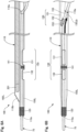
- Fig. 2 is an explanatory view illustrating the configuration of a part on the distal end side of the catheter 100.
- Fig. 3 is an explanatory view illustrating the configuration of the catheter 100 viewed from the A direction in Fig. 2 .
- Fig. 3 illustrates, in a balloon in the lower stage thereof, an enlarged sectional view of the vicinity of a branching part 150.
- Fig. 2 and Fig. 3 illustrate, in the upper stage thereof, a wire lumen 150L and a sensor lumen 160L formed in the catheter 100, with broken lines. Further, Fig. 2 and Fig. 3 partially illustrates, with a dashed line, a center axis O of the wire lumen 150L.
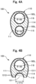
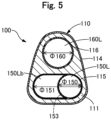
- Figs. 4A and 4B , and Fig. 5 are explanatory views illustrating the configuration of a transverse section of the catheter 100.
- Fig. 4A is a transverse sectional view of the catheter 100 along B1-B1 line of Fig. 2 .
- Fig. 4B is a transverse sectional view of the catheter 100 along B2-B2 line of Fig. 2 .
- Fig. 5 is a transverse sectional view of the catheter 100 along C-C line of Fig. 2 .
- Fig. 2 to Fig. 5 do not illustrate the imaging sensor 200 and the penetration guide wire 400.
- the catheter 100 includes a shaft 110 and an adjusting device 105.
- the shaft 110 includes the wire lumen 150L, the sensor lumen 160 L, a projection part 112, a notch part 130, and the branching part 150 ( Fig. 3 ).
- the wire lumen 150L and the sensor lumen 160L are lumens each extending in the longitudinal direction (X-axis direction) of the shaft 110. Inside the shaft 110, the wire lumen 150L and the sensor lumen 160L are arranged side by side to be parallel to each other.
- the sensor lumen 160L extends linearly from the distal end to the proximal end of the shaft 110. Meanwhile, as illustrated in Fig. 3 , the wire lumen 150L is branched to two directions at a position between the distal end and the proximal end of the shaft 110 (for example, an arbitrary position about 200 mm to 400 mm from the distal end). One of them extends substantially linearly to the proximal end of the shaft 110, and the other is communicated to the outside through a port 110e formed on a side surface of the shaft 110. In the following, the lumen branched from the wire lumen 150L and connected to the port 110e is also referred to as a "branching lumen 150Lb".
- the vicinity of the connection portion between the wire lumen 150L and the branching lumen 150Lb is also referred to as a "branching part 150".
- the details of the branching part 150 and the branching lumen 150Lb are described later.
- a part on the distal end side of the wire lumen 150L is positioned on the more distal end side (-X-axis side) than the distal end of the sensor lumen 160L.
- a part surrounding this part on the distal end side of the wire lumen 150L in the shaft 110 is also referred to as a "projection part 112". Note that the lengths in the X-axis direction of the wire lumen 150L and the sensor lumen 160L can be arbitrarily determined as long as the wire lumen 150L is longer than the sensor lumen 160L.
- the projection part 112 is a part of the shaft 110 projecting to the more distal end side than the distal end of the sensor lumen 160L, as described above, and includes therein a part on the distal end side of the wire lumen 150L.
- a distal tip 120 is jointed to a part on the distal end side of the projection part 112 so as to surround the projection part 112.
- the distal tip 120 is a substantially cylindrical member with an R provided to the distal end portion thereof. Note that the distal tip 120 may have an arbitrary shape, and may have a substantially truncated cone shape with the outer diameter reduced from the proximal end side to the distal end side, for example.
- the distal tip 120 may be colored to improve the visibility, and may be formed of a radiopaque material.
- To joint the distal tip 120 and the shaft 110 there may be adopted jointing of resin by hot melting or jointing with an insulating adhesive such as an epoxy-based adhesive.
- a distal end first opening 110a connecting the wire lumen 150L and the outside is provided at a position corresponding to the distal end of the wire lumen 150L (in other words, the distal end of the projection part 112).
- the distal end first opening 110a corresponds to a "distal end opening".
- a proximal end first opening 110c connecting the wire lumen 150L and the outside is provided at a position corresponding to the proximal end of the wire lumen 150L ( Fig. 1 ).
- a distal end second opening 110b connecting the sensor lumen 160L and the outside is provided at a position corresponding to the distal end of the sensor lumen 160L.
- a proximal end second opening 110d connecting the sensor lumen 160L and the outside is provided at a position corresponding to the proximal end of the sensor lumen 160L ( Fig. 1 ).
- the distal end second opening 110b is positioned on the more proximal end side than the distal end first opening 110a. Moreover, the distal end second opening 110b is inclined relative to the longitudinal direction (X-axis direction) of the shaft 110.
- the distal end second opening 110b is an opening for discharging liquid introduced into the sensor lumen 160L from the proximal end second opening 110d.
- the distal end second opening 110b may be vertical relative to the longitudinal direction of the shaft 110.
- the distal end second opening 110b may not be provided at a position corresponding to the distal end of the sensor lumen 160L, as long as it is provided at a position connecting a part of the vicinity of the distal end portion of the sensor lumen 160L and the outside.
- the shaft 110 includes an outer shaft 114, a first inner shaft 115, a second inner shaft 116, and a sealing member 111.
- the outer shaft 114, the first inner shaft 115, and the second inner shaft 116 all have a hollow elongated shape.
- the outer shaft 114 has a substantially elliptical transverse section.
- the first inner shaft 115 and the second inner shaft 116 have a substantially circular transverse section.
- the first inner shaft 115 and the second inner shaft 116 are inserted in the lumen of the outer shaft 114, and extend in substantially parallel to each other along the longitudinal direction of the outer shaft 114.
- the lumen of the first inner shaft 115 functions as the above-described wire lumen 150L.
- the lumen of the second inner shaft 116 functions as the above-described sensor lumen 160L. As illustrated in Fig.
- the inner diameter ⁇ 150 of the first inner shaft 115 is smaller than the inner diameter ⁇ 160 of the second inner shaft 116 (inner diameter of sensor lumen 160L). Note that the inner diameters ⁇ 150 and ⁇ 160 can be determined arbitrarily.
- the sealing member 111 seals (fixes) the first inner shaft 115 and the second inner shaft 116 in the outer shaft 114.
- the sealing member 111 is arranged inside the outer shaft 114 and outside the first inner shaft 115 and the second inner shaft 116.
- jointing of resin by hot melting or jointing with an insulating adhesive such as an epoxy-based adhesive.
- the notch part 130 is a notch formed in the shaft 110 on the more proximal end side than the projection part 112, the notch connecting the wire lumen 150L and the outside.
- the notch part 130 includes two notches (first notch 131, second notch 132).
- the first notch 131 is formed on a side surface of the shaft 110, the side surface being positioned on the opposite side of the sensor lumen 160L with the center axis O of the wire lumen 150L as a reference.
- the first notch 131 is elliptical including a long axis (hereinafter, also referred to as a "first long axis”) extending along the center axis O of the wire lumen 150L and a short axis (hereinafter, also referred to as a "first short axis”) extending vertically to the center axis O, when the shaft 110 is viewed from the side of the wire lumen 150L.
- first long axis hereinafter, also referred to as a "first long axis”
- first short axis hereinafter, also referred to as a "first short axis”
- a length L131a of the first short axis of the first notch 131 is equal to the inner diameter ⁇ 150 of the wire lumen 150L. Note that the expression “equal” in the embodiment indicates “almost same", and allows a tolerance for manufacturing error or the like.
- the shaft 110 includes, in the section where the first notch 131 is formed, a bottom portion 1311 and a pair of side walls 1312.
- the bottom portion 1311 is a part facing the first notch 131.
- the side wall 1312 is a part extending from the bottom portion 1311 to the opposite side of the sensor lumen 160L.
- the shaft 110 includes, in the section where the first notch 131 is formed, a substantially semicircular groove surrounded by the bottom portion 1311 and the side walls 1312.
- the second notch 132 is provided on the more distal end side than the first notch 131.
- the second notch 132 is formed on a side surface of the shaft 110, the side surface being on the same side as the first notch 131 (that is, the side surface positioned on the opposite side of the sensor lumen 160L with the center axis O of the wire lumen 150L as a reference).
- the side surface being on the same side as the first notch 131 (that is, the side surface positioned on the opposite side of the sensor lumen 160L with the center axis O of the wire lumen 150L as a reference).
- the second notch 132 is elliptical including a long axis (hereinafter, also referred to as a "second long axis”) extending along the center axis O of the wire lumen 150L and a short axis (hereinafter, also referred to as a "second short axis”) extending vertically to the center axis O, when the shaft 110 is viewed from the side of the wire lumen 150L.
- a length L132a of the second short axis of the second notch 132 is equal to the inner diameter ⁇ 150 of the wire lumen 150L.
- the shaft 110 includes, in the section where the second notch 132 is formed, a bottom portion facing the second notch 132, and a pair of side walls extending from the bottom portion to the opposite side of the sensor lumen 160L. The details are the same as those of the first notch 131.
- a length L132b of the second long axis of the second notch 132 is shorter than a length L131b of the first long axis of the first notch 131.
- the area of the elliptical shape of the second notch 132 is smaller than the area of the elliptical shape of the first notch 131, when the shaft 110 is viewed from the side of the wire lumen 150L.
- the length L132b of the second axis of the second notch 132 indicates a length between the end on the distal end side and the end on the most proximal end side of the elliptical shape of the second notch part 132, when the shaft 110 is viewed from the side of the wire lumen 150L (viewpoint in Fig. 3 ). This also applies to the length L131b of the first long axis of the first notch 131.
- a marker 141 is jointed between the first notch 131 and the second notch 132 on the outer peripheral surface of the shaft 110.
- the marker 141 is a semicircular member along the outer peripheral surface of the shaft 110.
- the marker 141 may be colored to improve the visibility, and may be formed of a radiopaque material.
- To joint the marker 141 and the shaft 110 there may be adopted jointing of resin by hot melting or jointing with an insulating adhesive such as an epoxy-based adhesive.
- the second notch 132 is provided on the more distal end side than the first notch 131.
- the second notch 132 may be provided on the more proximal end side ( Figs. 2 and 3 : +X-axis direction) than the first notch 131.
- the marker 141 may be omitted.
- the distal end side of the branching lumen 150Lb is connected to the wire lumen 150L.
- the proximal end side of the branching lumen 150Lb is positioned on the more proximal end side of the shaft 110 than the distal end side.
- the proximal end side of the branching lumen 150Lb is communicated to the outside through the port 110e formed on the side surface of the shaft 110.
- the port 110e as an opening connecting the branching lumen 150Lb and the outside is provided at a position corresponding to the proximal end of branching lumen 150Lb in the shaft 110.
- the branching lumen 150Lb extends in a direction separate from the wire lumen 150L toward the proximal end side from the distal end side of the shaft 110.
- the branching part 150 includes a large diameter portion 151, a raised portion 152, and a boundary wall 153.
- the large diameter portion 151 (lower stage in Fig. 3 : circle with a broken line) is a part where the inner diameter of the lumen is relatively larger than that of other parts of the wire lumen 150L.
- the inner diameter ⁇ 151 of the lumen in the large diameter portion 151 is larger than the inner diameter ⁇ 150 of the wire lumen 150L.
- the inner diameter in the longitudinal direction of the substantially elliptical lumen is referred to as an "inner diameter ⁇ 151 of the lumen".
- Fig. 5 illustrates, with a dashed line, the boundary wall 153 not apparent on the C-C section.
- the raised portion 152 is a portion, in the inner peripheral surface of the branching part 150, where a part of an inner peripheral surface 152i defining the wire lumen 150L is raised.
- the raised portion 152 is provided in an area on the more distal end side than the large diameter portion 151 and on the opposite side of the side where the branching lumen 150Lb extends.
- the inner peripheral surface 152i of the branching part 150 is raised to the side where the branching lumen 150Lb extends.
- the raised portion 152 of the embodiment has a shape smoothly raised from the inner peripheral surface 152i of the branching part 150.
- the length in the longitudinal direction (X-axis direction) of the shaft 110 of the raised portion 152 may be determined arbitrarily.
- the boundary wall 153 is a part of the shaft 110 provided on the more proximal end side than the large diameter portion 151, the part separating the wire lumen 150L and the branching lumen 150Lb from each other.
- the boundary wall 153 of the embodiment has a curved plate shape.
- the boundary 153 may have an arbitrary shape such as a plate shape or a pinnate shape as long as it separates the wire lumen 150L and the branching lumen 150Lb from each other.
- the boundary 153 may have an arbitrary shape such as a plate shape or a pinnate shape as long as it separates the wire lumen 150L and the branching lumen 150Lb from each other.
- a distal end P1 of the boundary wall 153 is positioned on the more distal end side than a distal end P2 of the port 110e in the longitudinal direction (X-axis direction) of the shaft 110.
- the distal end P1 of the boundary 153 may be at the same position as the distal end P2 of the port 110e.
- the expression "same” indicates “almost same", and allows a difference due to a manufacturing error or the like.
- the length L153 in the X-axis direction of the boundary wall 153 is equal to or longer than the length L110 in the X-axis direction of the port 110e.
- the port 110e is inclined relative to the center axis O of the shaft 110.
- the length L110 in the X-axis direction of the port 110e indicates a length measured when the port 110e is projected on the X axis, as illustrated in the lower stage of Fig. 3 .
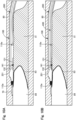
- Figs. 6A and 6B are diagrams for explaining an action of the raised portion 152 in the first case.
- Fig. 6A illustrates a side view of the catheter 100 viewed from the same direction as Fig. 2
- Fig. 6B illustrates a bottom view of the catheter 100 viewed from the same direction as Fig. 3 .
- Figs. 6A and 6B illustrate a delivery guide wire 70, as an example of the wire, with dot hatching.
- the "first case” indicates a case where the delivery guide wire 70 is inserted to the wire lumen 150L from the distal end first opening 110a and advances in the wire lumen 150L from the distal end side toward the proximal end side.
- the first case is a case where the catheter 100 is used as a rapid exchange type (Rx-type) catheter.
- an operator inserts the proximal end portion of the delivery guide wire 70 to the wire lumen 150L from the distal end first opening 110a, and pulls it out to the outside from the port 110e through the branching lumen 150Lb.
- the proximal end portion of the delivery guide wire 70 comes into contact with the raised portion 152, thereby automatically advancing toward the side of the branching lumen 150Lb (direction of a bold arrow) and being guided to the outside from the port 110e at the proximal end of the branching lumen 150Lb.
- Figs. 7A and 7B are diagrams for explaining an action of the boundary wall 153 in the second case.
- Fig. 7A illustrates a side view of the catheter 100 viewed from the same direction as Fig. 2
- Fig. 7B illustrates a bottom view of the catheter 100 viewed from the same direction as Fig. 3 .
- Figs. 7A and 7B illustrate the penetration guide wire 400, as an example of the wire, with dot hatching.
- the "second case” indicates a case where the penetration guide wire 400 is inserted to the wire lumen 150L from the proximal end first opening 110c and advances in the wire lumen 150L from the proximal end side toward the distal end side.
- the second case is a case where the catheter 100 is used as an over the wire type (OTW-type) catheter.
- an operator inserts the distal end portion of the penetration guide wire 400 to the wire lumen 150L from the distal end second opening 110b so that it advances in the branching part 150 (without letting the penetration guide wire 400 wrongly enter the branching lumen 150Lb), and pulls it out to the outside from the first notch 131 or the second notch 132.
- the distal end portion of the penetration guide wire 400 comes into contact with the boundary wall 153, thereby automatically advancing straight in the branching part 150 (in the bold arrow direction) while being suppressed from advancing toward the branching lumen 150Lb, and reaches the part where the first notch 131 or the second notch 132 is provided.
- the adjusting device 105 is an operation part for moving the imaging sensor 200 in the sensor lumen 160L forward and backward.
- the adjusting device 105 includes a dial operable by an operator. With the rotation of the dial, the imaging sensor 200 inserted in the sensor lumen 160L is moved forward or backward.
- the outer shaft 114, the first inner shaft 115, the second inner shaft 116, the sealing member 111, and the adjusting device 105 may be formed of known materials including, for example, nylon resin such as polyamide, polyolefins such as polyethylene, polypropylene, and ethylene-propylene copolymers, polyesters such as polyethylene terephthalate, thermoplastic resin such as polyvinyl chloride, ethylene-vinyl acetate copolymers, crosslinked ethylene-vinyl acetate copolymers, and polyurethanes, polyamide elastomer, polyolefin elastomer, polyurethane elastomer, silicone rubber, latex rubber, or the like.
- nylon resin such as polyamide
- polyolefins such as polyethylene, polypropylene, and ethylene-propylene copolymers
- polyesters such as polyethylene terephthalate
- thermoplastic resin such as polyvinyl chloride, ethylene-vinyl acetate cop
- the outer shaft 114, the first inner shaft 115, the second inner shaft 116, the sealing member 111, and the adjusting device 105 may be formed of the same material, or at least some of them or all of them may be formed of a different material from the other components.
- the outer shaft 114, the first inner shaft 115, the second inner shaft 116, and the sealing member 111 at least a part positioned in the vicinity of the notch part 130 (first notch 131 and second notch 132) is preferably formed of resin having a small difference in acoustic impedance from the living tissue, such as polyethylene, for example. This is not to inhibit ultrasonic waves emitted to the living tissue from the imaging sensor 200.
- the distal tip 120 and the marker 141 are formed of a flexible resin material such as a polyurethane elastomer, for example.
- the distal tip 120 and the marker 141 may be formed of a radiopaque resin material or metal material.
- a radiopaque resin material for example, a radiopaque material such as bismuth trioxide, tungsten, or barium sulfate is mixed to polyamide resin, polyolefin resin, polyester resin, polyurethane resin, silicone resin, fluororesin, or the like.
- a radiopaque metals for example, gold, platinum, tungsten, an alloy containing these elements (for example, a platinum-nickel alloy) can be used.
- the distal tip 120 and the marker 141 may be formed of the same material or different materials.
- Fig. 8 is a schematic view of the imaging sensor 200.
- the imaging sensor 200 is a "sensor" with an elongated shape that acquires the information of a living tissue.
- the imaging sensor 200 includes a transducer 201, a driving cable 202, and a connector 203.
- the transducer 201 includes an ultrasonic probe (also referred to as an ultrasonic vibrator, a piezoelectric body, an ultrasonic transmitting/receiving element, or an ultrasonic element) that emits ultrasonic waves to a living tissue and receives ultrasonic waves reflected during propagation in the living tissue.
- the driving cable 202 includes therein a coaxial cable electrically connecting the transducer 201 and the motor drive 204.
- the connector 203 connects the coaxial cable of the driving cable 202 and the motor drive 204 controlling the rotation of the transducer 201.
- the motor drive 204 is electrically connected to the imaging console 300 by a cable 50.
- the imaging console 300 illustrated in Fig. 1 controls the imaging sensor 200, generates an image, and displays the image.
- the imaging console 300 moves the transducer 202 in the sensor lumen 160L in the longitudinal direction of the shaft 110 (X-axis direction) or rotates the transducer 201 in the circumferential direction of the shaft 110 (YZ-axis direction).
- the imaging console 300 controls the transducer 201 to emit ultrasonic waves and receive reflected waves. The reflected waves received by the transducer 201 is transmitted to the imaging console 300 through the driving cable 202 and the cable 50.
- the imaging console 300 generates an image (two-dimensional image) with tone gradation in accordance with the intensity of the received reflected waves, and displays the generated image on a display 302.
- the image acquired by the imaging sensor 200 and displayed on the display 302 is also referred to as a "sensor image”.
- the penetration guide wire 400 illustrated in Fig. 1 is an elongated medical device including a pointed portion at the distal end thereof.
- the pointed portion is a portion having an arrowhead shape or a wedge shape from the proximal end side toward the distal end side. With the pointed portion provided at the distal end, the penetration guide wire 400 can penetrate the living tissue.
- the penetration guide wire 400 corresponds to "a guide wire penetrating a living tissue".
- Figs. 9A and 9B , and Figs. 10A and 10B are diagrams for explaining a use method of the recanalization catheter system 1.
- Figs. 9A and 9B , and Figs. 10A and 10B each illustrates a coronary artery 80 as an example of a living body lumen, a CTO 81 occurred in the coronary artery 80, a false lumen 82 formed in the intima or under the intima of the coronary artery 80 (all dissected lumens formed by the delivery guide wire 70, other than true lumens), a true lumen 84, a fibrotic film or a plaque 83 (hereinafter, also referred to as a "fibrotic film” 83) present between the false lumen 82 and the true lumen 84.
- the fibrotic film 83 may be formed in a fiber form on the surface of a CTO lesion.
- Fig. 9A illustrates the coronary artery 80 in which the delivery guide wire 70 is inserted.
- the delivery guide wire 70 operated by an operator wrongly enters an intima of the coronary artery 80, or forms the false lumen 82 below the intima.
- Fig. 9B illustrates a situation in which the catheter 100 is delivered using the delivery guide wire 70.
- the operator performs the operation described in Figs. 6A and 6B to insert the delivery guide wire 70 to the catheter 100.
- the raised portion 152 guides the proximal end portion of the delivery guide wire 70 to the branching lumen 150Lb where the port 110e is provided.
- the port 110e is provided.
- the catheter 100 of the embodiment shortens a feeding distance of the delivery guide wire 70 in the wire lumen 150L, as compared with the conventional case where the delivery guide wire 70 is pulled out from the proximal end first opening 110c ( Fig. 1 ) on the proximal end side. As a result, it is possible to reduce time required for inserting the delivery guide wire 70 to the catheter 100. Thereafter, the operator delivers the catheter 100 to the false lumen 82 along the delivery guide wire 70, as illustrated in Fig. 9B .
- Fig. 10A illustrates a situation where the positions of the catheter 100 and the imaging sensor 200 are adjusted. The operator adjusts each of the positions described in the following a1 to a3. Note that the adjustment a2 may be omitted.
- Fig. 10B illustrates a situation in which the penetration guide wire 400 penetrates a living tissue.
- the operator removes the delivery guide wire 70.
- the length of the delivery guide wire 70 inserted in the wire lumen 150L is shorter than the conventional case described in Fig. 8B, which allows the delivery guide wire 70 to be removed more easily than the conventional case.
- the operator After removing the delivery guide wire 70, the operator performs the operation described in Figs. 7A and 7B to insert the penetration guide wire 400 to the catheter 100.
- the boundary wall 153 suppresses the distal end portion of the penetration guide wire 400 from wrongly entering the branching lumen 150Lb. Therefore, the distal end portion of the penetration guide wire 400 can smoothly project from the first notch 131 or the second notch 132.
- the operator guides the pointed portion of the penetration guide wire 400 to the above-described optimal position for penetration while confirming the distal end of the penetration guide wire 400 on the sensor image. Thereafter, the pointed portion of the penetration guide wire 400 penetrates a living tissue (target tissue), so that the distal end of the penetration guide wire 400 reaches the true lumen 84.
- Such a method enables recanalization of the CTO 81 in the recanalization catheter system 1.
- the above-described method is merely an example, and the recanalization catheter system 1 can be used in various procedures.
- the recanalization catheter system 1 may be used not only for the approach from the false lumen 82 to the true lumen 84 but also for the approach to penetrate a CTO from the true lumen 84 on the near side to the true lumen 84 on the far side.
- the shaft 110 includes the wire lumen 150L and the sensor lumen 160L arranged side by side with the wire lumen 150L.
- the catheter 100 capable of realizing the procedure under guidance of the imaging sensor 200 (for example, IVUS) inserted in the sensor lumen 160L and performing the procedure while different medical devices (for example, the delivery guide wire 70 and the penetration guide wire 400) are exchanged in the wire lumen 150L ( Figs. 9A and 9B , Figs. 10A and 10B ).
- the distal end first opening 110a is formed at the distal end of the projection part 112, which allows the delivery guide wire 70 to be easily inserted in the wire lumen 150L from this distal end first opening 110a ( Fig. 6A ).
- the shaft 110 in the section where the first notch 131 is formed, includes the bottom portion 1311 facing the first notch 131, and the pair of side walls 1312 extending from the bottom portion 1311 to the opposite side of the sensor lumen 160L ( Fig. 4B ).
- the side surface positioned on the opposite side of the sensor lumen 160L includes the first notch 131.
- the catheter 100 of the first embodiment is the catheter 100 capable of realizing the procedure under guidance of the imaging sensor 200 and performing the procedure while different medical devices are exchanged, in which both the reduction in diameter and the improvement of usability are possible.
- the first notch 131 is elliptical, and the length L131a of the first short axis of the first notch 131 is equal to the inner diameter ⁇ 150 of the wire lumen 150L.
- the first notch 131 can be provided in a wide range in the circumferential direction of the wire lumen 150L ( Fig. 3 ). Therefore, when the catheter 100 is inserted in the living body lumen, the distal end portion of the penetration guide wire 400 can be easily directed to the target tissue without rotating the catheter 100 even if the position of the first notch 131 of the catheter 100 is separate from the position in the circumferential direction of the living tissue (target tissue). Consequently, in the catheter 100 of the first embodiment, the above-described adjustment a2, for example, may be omitted.
- the side surface of the shaft 110 further includes the second notch 132 on the more distal end side or proximal end side than the first notch 131 ( Fig. 2 , Fig. 3 ). Therefore, the penetration guide wire 400 can project to the outside selectively from either the first notch 131 or the second notch 132.
- the shaft 110 includes the bottom portion facing the second notch 132, and the pair of side walls extending from the bottom portion to the opposite side of the sensor lumen.
- the distal end portion of the penetration guide wire 400 can be pushed out to the outside.
- the distal end portion of the penetration guide wire 400 can accurately project to the living tissue (target tissue).
- the second notch 132 is elliptical, and the length of the second short axis L132a of the second notch 132 is equal to the inner diameter of the wire lumen 150L.
- the second notch 132 can be provided in a wide range in the circumferential direction of the wire lumen 150L ( Fig. 3 ). Therefore, when the catheter 100 is inserted in the living body lumen, the distal end portion of the penetration guide wire 400 can be easily directed to the target tissue without rotating the catheter 100 even if the position of the second notch 132 of the catheter 100 is separate from the position in the circumferential direction of the living tissue (target tissue).
- the length L132b of the second long axis of the second notch 132 is shorter than the length L131b of the first long axis of the first notch 131.
- the length of the second notch 132 in the longitudinal direction of the shaft 110 can be shorter than the length of the first notch 131 ( Fig. 3 ). Therefore, the positioning of the distal end portion of the penetration guide wire 400 relative to the target tissue is easier at the second notch 132 than at the first notch 131.
- the operator can selectively use either the first notch 131 or the second notch 132 depending on the position relation between the catheter 100 and a target tissue or a situation such as the size of a target tissue, which further improves usability of the catheter 100.
- the shaft 110 includes the distal end first opening 110a at the distal end of the projection part 112, which allows the delivery guide wire 70 to be easily inserted in the wire lumen 150L from this distal end first opening 110a ( Fig. 6A ).
- the proximal end side of the branching lumen 150Lb branched from the wire lumen 150L is communicated to the outside through the port 110e formed on the side surface of the shaft 110.
- the proximal end portion of the delivery guide wire 70 in the wire lumen 150L can be pulled out to the outside from the port 110e, which allows the delivery guide wire 70 to be quickly inserted in the catheter 100 ( Fig. 6A ).
- the branching part 150 formed at the connection portion between the wire lumen 150L and the branching part 150Lb includes the boundary wall 153 separating the wire lumen 150L and the branching lumen 150Lb from each other ( Fig. 5 ).
- the catheter 100 of the first embodiment is the catheter 100 capable of realizing the procedure under guidance of the imaging sensor 200 and performing the procedure while different medical devices are exchanged, in which both the reduction in diameter and the improvement of usability are possible.
- the distal end P1 of the boundary wall 153 is located at the same position as the distal end position P2 of the port 110e, or on the more distal end side than the distal end position P2 of the port 110e (lower stage in Fig. 3 ).
- the penetration guide wire 400 is inserted in the wire lumen 150L from the proximal end side of the shaft 110 and pushed toward the distal end side of the shaft 110, it is possible to securely suppress the distal end portion of the penetration guide wire 400 from advancing toward the branching lumen 150Lb.
- the length L153 in the longitudinal direction of the shaft 110 of the boundary wall 153 is equal to or longer than the length L110 in the longitudinal direction of the shaft 110 of the port 110e (lower stage in Fig. 3 ).
- the branching part 150 further includes the raised portion 152.
- the proximal end portion of the delivery guide wire 70 is brought into contact with the raised portion 152, thereby guiding the proximal end portion of the delivery guide wire 70 toward the branching lumen 150Lb ( Fig. 6B ).
- the raised portion 152 guides the proximal end portion of the delivery guide wire 70 toward the branching lumen 150Lb with the port 110e, thereby improving usability as the Rx-type catheter 100.
- the boundary wall 153 of the branching part 150 in the second case where the penetration guide wire 400 is inserted in the wire lumen 150L from the proximal end side of the shaft 110, the distal end portion of the penetration guide wire 400 is brought into contact with the boundary wall 153, thus suppressing the distal end portion of the penetration guide wire 400 from advancing toward the branching lumen 150Lb ( Fig. 7B ).
- the boundary wall 153 guides the distal end portion of the penetration guide wire 400 toward the distal end of the wire lumen 150L, thereby improving usability as the OTW-type catheter 100.
- the wire lumen 150L can be shared by different medical devices (delivery guide wire 70, penetration guide wire 400), which reduces the diameter of the catheter 100.
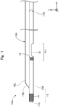
- Fig. 11 is an explanatory view illustrating the configuration of a part on the distal end side of a catheter 100A according to the second embodiment.
- the recanalization catheter system 1 of the first embodiment includes the catheter 100A illustrated in Fig. 11 instead of the catheter 100 described in the first embodiment.
- a shaft 110A of the catheter 100A includes a notch part 130A instead of the notch part 130.
- the notch part 130A does not include the second notch 132 described in the first embodiment, and includes only the single first notch 131.
- the configuration of the notch part 130A can be changed variously, and the notch part 130A may be formed only by the single first notch 131.
- the marker 141 may be arranged on the more distal end side than the first notch 131, or may be arranged on the more proximal end side than the first notch 131.
- Such a catheter 100A of the secondembodiment can also exert similar effects as in the above-described first embodiment.
- Fig. 12 is an explanatory view illustrating the configuration of a part on the distal end side of a catheter 100B according to the third embodiment.
- the recanalization catheter system 1 of the second embodiment includes the catheter 100B illustrated in Fig. 12 instead of the catheter 100 described in the first embodiment.
- a shaft 110B of the catheter 100B includes a notch part 130B instead of the notch part 130.
- the notch part 130 further includes a third notch 133 in addition to the first notch 131 and the second notch 132 that are described in the first embodiment.
- the third notch 133 is provided on the more distal end side than the second notch 132.
- the third notch 133 is formed on the side surface on the same side as the first notch 131.
- the third notch 133 is elliptical including a long axis and a short axis. The length of the short axis of the third notch 133 is equal to the inner diameter ⁇ 150 of the wire lumen 150L.
- the length L133b of the long axis of the third notch 133 is shorter than the length L131b of the first long axis of the first notch 131, and is shorter than the length L132b of the second long axis of the second notch 132.
- the shaft 110B includes a bottom portion facing the third notch 133, and a pair of side walls extending from the bottom portion to the opposite side of the sensor lumen 160L.
- a second marker 142 is jointed between the second notch 132 and the third notch 133 on the outer peripheral surface of the shaft 110B.
- the second marker 142 is a semicircular member along the outer peripheral surface of the shaft 110B.
- the second marker 142 may be colored to improve the visibility, and may be formed of a radiopaque material.
- the configuration of the notch part 130B can be changed variously, and the notch part 130B may be formed by three or more notches (first notch 131, second notch 132, third notch 133). Moreover, the third notch 133 may be provided on the more proximal end side than the first notch 131.
- Such a catheter 100B of the third embodiment can also exert similar effects as in the above-described first embodiment.
- Fig. 13 is an explanatory view illustrating the configuration of a part on the distal end side of a catheter 100C according to the fourth embodiment.
- Fig. 13 is a bottom view of the catheter 100C viewed from the same direction as in Fig. 3 .
- the recanalization catheter system 1 of the fourth embodiment includes the catheter 100C illustrated in Fig. 13 instead of the catheter 100 described in the first embodiment.
- the shaft 110C of the catheter 100C includes a branching part 150C instead of the branching part 150.
- the branching part 150C does not include the raised portion 152 and the boundary wall 153 that are described in the first embodiment.
- the configuration of the branching part 150C can be changed variously, and the branching part 150C may not include at least one of the raised portion 152 and the boundary wall 153, or may not include both of them.
- Such a catheter 100C of the fourth embodiment can also exert similar effects as in the above-described first embodiment, except the wire guiding effect in the first case and the second case.
- Fig. 14 is an explanatory view illustrating the configuration of a transverse section of a catheter 100D according to a fifth embodiment.
- Fig. 14 illustrates, in the upper stage thereof, a transverse sectional view along B2-B2 line of Fig. 2 , and illustrates, in the lower stage thereof, an explanatory view of the range where a first notch 131D is provided.
- the recanalization catheter system 1 of the fourth embodiment includes the catheter 100D illustrated in Fig. 14 instead of the catheter 100 described in the first embodiment.
- a shaft 110D of the catheter 100D includes the first notch 131D instead of the first notch 131 described in the first embodiment.
- the first notch 131D is formed on the same side as the first notch 131 described in the first embodiment, and is elliptical including a first short axis and a first long axis. Meanwhile, the angle of the first notch 131 in the entire circumference of the wire lumen 150L is about 180° in the first notch 131 of the first embodiment, while the angle ⁇ of the first notch 131D in the entire circumference of the wire lumen 150L is about 240° in the first notch 131D of the fifth embodiment (lower stage in Fig. 14 ). Thus, a side wall 1312D of the first notch 131D is shorter than the side wall 1312 described in the first embodiment. Moreover, the length L131a of the first short axis of the first notch 131D is shorter than the inner diameter ⁇ 150 of the wire lumen 150L.
- the configuration of the first notch 131D can be changed variously, and the angle ⁇ of the first notch 131D in the entire circumference of the wire lumen 150L can be changed arbitrarily.
- the angle of the second notch 132 in the entire circumference of the wire lumen 150L may be changed arbitrarily.
- Such a catheter 100D of the fifth embodiment can also exert similar effects as in the above-described first embodiment.
- Fig. 15 is an explanatory view illustrating the configuration of a transverse section of a catheter 100E according to the sixth embodiment.
- Fig. 15 illustrates the configuration of the transverse section along B1-B1 line in Fig. 2 .
- the recanalization catheter system 1 of the sixth embodiment includes the catheter 100E illustrated in Fig. 15 instead of the catheter 100 described in the first embodiment.
- a shaft 110E of the catheter 100E does not include the outer shaft 114, the first inner shaft 115, the second inner shaft 116, and the sealing member 111 that are described in the first embodiment, and is formed by the single shaft 110E. Except the point that the shaft 110E is formed by the single member, the shaft 110E has the same configuration as the shaft 110 described in the first embodiment. That is, the shaft 110E includes the wire lumen 150L, the sensor lumen 160L, the projection part 112, the notch part 130, and the branching part 150 that are described in the first embodiment.
- the configuration of the catheter 100E can be changed variously, and the catheter 100E may be formed only by the single shaft 110E.
- the shaft 110E may not include the outer shaft 114 and the sealing member 111, and may be formed by the first inner shaft 115 and the second inner shaft 116 jointed to each other.
- the shaft 110E may not include the sealing member 111, and may be formed by the first inner shaft 115 and the second inner shaft 116 housed in the outer shaft 114.
- Such a catheter 100E of the sixth embodiment can also exert similar effects as in the above-described first embodiment.
- Fig. 16 is an explanatory view illustrating the configuration of a transverse section of a catheter 100F according to the seventh embodiment.
- Fig. 16 illustrates the configuration of the transverse section along C-C line in Fig. 2 .
- the recanalization catheter system 1 of the seventh embodiment includes the catheter 100F illustrated in Fig. 16 instead of the catheter 100 described in the first embodiment.
- the wire lumen 150L and the branching lumen 150Lb are arranged inclined relative to the Z-axis direction.
- the configuration of the shaft 110F can be changed variously, and the arrangement of the wire lumen 150L, the branching lumen 150Lb, and the sensor lumen 160L in the shaft 110F can be changed arbitrarily.
- Such a catheter 100F of the seventh embodiment can also exert similar effects as in the above-described first embodiment.
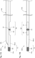
- Figs. 17A and 17B are explanatory views illustrating the configuration of a part on the distal end side of a catheter 100G according to the eighth embodiment.
- Fig. 17A illustrates a side view of the catheter 100G
- Fig. 7B illustrates a bottom view of the catheter 100G.
- the recanalization catheter system 1 of the eighth embodiment includes the catheter 100G illustrated in Figs. 17A and 17B instead of the catheter 100 described in the first embodiment.
- a shaft 110G of the catheter 100G includes a wire lumen 150LG instead of the wire lumen 150L described in the first embodiment.
- the wire lumen 150LG is not branched, and extends linearly from the distal end to the proximal end of the shaft 110G.
- the shaft 110G does not include the branching lumen 150Lb, the port 110e, the branching part 150, the large diameter portion 151, the raised portion 152, nor the boundary wall 153 that are described in the first embodiment.
- the proximal end portion of the delivery guide wire 70 is pulled out from the proximal end first opening 110c of the shaft 110G.
- the configuration of the shaft 110G can be changed variously, and the shaft 110G may include the wire lumen 150LG that is not branched.
- Such a catheter 100G of the eighth embodiment can also exert similar effects as in the above-described effect example 1 of the effects described above in the first embodiment.
- Figs. 18A and 18B are explanatory views illustrating the configuration of a part on the distal end side of a catheter 100H according to the ninth embodiment.
- Fig. 18A illustrates a side view of the catheter 100H
- Fig. 18B illustrates a bottom view of the catheter 100H.
- the recanalization catheter system 1 of the ninth embodiment includes the catheter 100H illustrated in Figs. 18A and 18B instead of the catheter 100 described in the first embodiment.
- a shaft 110H of the catheter 100H does not include the notch part130 (first notch 131, second notch 132) described in the first embodiment.
- the distal end portion of the penetration guide wire 400 projects from the distal end first opening 110a of the shaft 110H.
- the configuration of the shaft 110H can be changed variously, and the shaft 110H may not include the notch part 130.
- Such a catheter 100H of the ninth embodiment can also exert similar effects as in the above-described effect example 2 of the effects described above in the first embodiment.
- the above first to ninth embodiments show examples of the configurations of the recanalization catheter system 1.
- the configurations of the recanalization catheter system 1 can be variously changed.
- the imaging sensor 200 there may be used a sensor that acquires images of living tissues by a method other than transmission and reception of ultrasonic waves.
- an optical coherence tomography (OCT) or a camera instead of the imaging sensor 200, may be inserted to acquire images of living tissues in blood vessels.
- the recanalization catheter system 1 may be formed as a system for CTO recanalization using a plasma guide wire for ablation of living tissues utilizing plasma, instead of using the penetration guide wire 400.
- an electrode is preferably provided at the distal end portion of the shaft 110.
- ablation of living tissues is possible using energy emitted by discharge between the both electrodes.
- the electrode at the distal end portion of the shaft 110 is preferably arranged on the more proximal end side than the distal tip 120 and the more distal end side than the notch part 130.
- the recanalization catheter system 1 may be used in a method other than the above-described methods.
- the recanalization catheter system may be used in a blood vessel other than the coronary artery (for example, a cerebral blood vessel or the like), and may be used in a living body lumen other than blood vessels.
- the recanalization catheter system 1 may be used in therapeutics other than the recanalization catheter system, or in examinations.
- the above first to ninth embodiments show examples of the configurations of the catheters 100, 100A to 100H.
- the configurations of the catheters 100, 100A to 100H can be variously changed.
- the wire lumen 150L and the sensor lumen 160L of the catheter 100 may have a substantially same diameter, or the wire lumen 150L may be configured to have a smaller diameter than the sensor lumen 160L.
- the catheter 100 may further include, in addition to the wire lumen 150L and the sensor lumen 160L, a lumen for another medical device or for the delivery guide wire 70 and the penetration guide wire 400 to be inserted at the same time.
- the distal end P1 (lower stage of Fig. 3 ) of the boundary wall 153 may be positioned on the more proximal end side than the distal end P2 of the port 110e.
- the length L153 (lower stage of Fig. 3 ) in the longitudinal direction of the shaft 110 of the boundary wall 153 may be smaller than the length L110 in the longitudinal direction of the shaft 110 of the port 110e.
- any of the outer surfaces of the shaft 110, 110A to 110H, the outer surface or the inner surface of the first inner shaft 115, the outer surface or the inner surface of the second inner shaft 116, and the outer surface or the inner surface of the outer shaft 114 may be coated with an arbitrary resin layer (for example, a hydrophilic resin layer, a hydrophobic resin layer, an underlayer for improving joinability of a hydrophilic resin layer and a hydrophobic resin layer, or the like), or a chemical agent may be applied on the surface.
- an arbitrary resin layer for example, a hydrophilic resin layer, a hydrophobic resin layer, an underlayer for improving joinability of a hydrophilic resin layer and a hydrophobic resin layer, or the like
- a chemical agent may be applied on the surface.
- the catheter 100G described in the eighth embodiment may have the configuration described in the second, third, fourth, or seventh embodiment.
- the catheter 100H described in the ninth embodiment may have the configuration described in the fourth embodiment.
- the catheters 100A, B described in the second or third embodiment may have the configuration described in the fifth or seventh embodiment.
- the catheters 100A to D, F to H described in the second to fifth and the seventh to ninth embodiments may have the configuration described in the sixth embodiment.
Landscapes
- Health & Medical Sciences (AREA)
- Life Sciences & Earth Sciences (AREA)
- Veterinary Medicine (AREA)
- Public Health (AREA)
- Engineering & Computer Science (AREA)
- Animal Behavior & Ethology (AREA)
- Biomedical Technology (AREA)
- Heart & Thoracic Surgery (AREA)
- General Health & Medical Sciences (AREA)
- Biophysics (AREA)
- Hematology (AREA)
- Pulmonology (AREA)
- Anesthesiology (AREA)
- Surgery (AREA)
- Physics & Mathematics (AREA)
- Nuclear Medicine, Radiotherapy & Molecular Imaging (AREA)
- Medical Informatics (AREA)
- Molecular Biology (AREA)
- Geometry (AREA)
- Vascular Medicine (AREA)
- Orthopedic Medicine & Surgery (AREA)
- Pathology (AREA)
- Radiology & Medical Imaging (AREA)
- Media Introduction/Drainage Providing Device (AREA)
- Ultra Sonic Daignosis Equipment (AREA)
Abstract
Description
- The disclosed embodiments relate to a catheter.
- An occlusion may block a blood vessel, such as a Chronic Total Occlusion (CTO). In the procedure of CTO recanalization, a catheter is generally delivered to a position of a CTO lesion using a delivery catheter, and then a penetration guide wire is introduced from a false lumen to a true lumen. Note that the false lumen indicates all dissected lumens formed by medical devices, other than true lumens.
- Because of the complicated procedure for CTO recanalization, the procedure performed under sensor guidance (IVUS guide, for example) has been demanded. For example, Patent Literatures 1 to 3 disclose catheters that can be used in the procedure under sensor guidance. The catheters in Patent Literatures 1 to 3 include a sensor lumen (image lumen) and a wire lumen (guide wire lumen) separately, so that a penetration guide wire inserted in the wire lumen can be operated under observation by a sensor inserted in the sensor lumen.
-
- [Patent Literature 1]
JP 4065167 B2 - [Patent Literature 2]
JP 2017-153621 A - [Patent Literature 3]
JP 2018-33507 A - Here, the diameter of a catheter inserted in a blood vessel is preferably as small as possible. In the catheters described in Patent Literatures 1 and 2, the diameter of the catheter can be reduced because both a delivery guide wire and a penetration guide wire use a single wire lumen. Meanwhile, in the catheters described in Patent Literatures 1 and 2, the wire lumen extending in the longitudinal direction of the catheter includes a first guide wire lumen and a second guide wire lumen, with an area between the first and second guide wire lumens where a guide wire lumen is not present. Therefore, in the catheters described in Patent Literatures 1 and 2, when a delivery guide wire is inserted into the catheter, the delivery guide becomes detached in an area where a guide wire lumen is not present, thus deteriorating usability. Moreover, the catheter described in Patent Literature 3 includes three wire lumens, which improves usability but increases the diameter of the catheter.
- Such a problem arises not only in CTO recanalization, but is common to all devices for the procedures performed while different medical devices, such as a delivery guide wire and a penetration guide wire, are exchanged. Moreover, such a problem is also common not only to devices to be inserted into blood vessels, but also to all devices to be inserted into living body lumens, such as the lymph gland system, the biliary system, the urinary tract system, the airway system, the digestive organ system, secretory glands, and reproductive organs.
- In order to solve at least a part of the above-described problems, the disclosed embodiments aim at providing a catheter capable of realizing procedures under sensor guidance and performing procedures while different medical devices are exchanged, in which both the reduction in diameter and the improvement of usability are possible.
- Disclosed embodiments have been made to solve at least a part of the above-described problems, and can be realized as the following aspects.
-
- (1) According to one aspect of the disclosed embodiments, a catheter with a shaft is provided. In the catheter, the shaft includes a wire lumen extending in a longitudinal direction of the shaft; a sensor lumen that is arranged side by side with the wire lumen; a projection part that includes the wire lumen, projects to the more distal side than the distal end of the sensor lumen, and has a distal end opening communicated to the wire lumen at the distal end of the projection part; and a first notch that is a notch formed on the more proximal end side than the projection part, and is communicated to the wire lumen. The first notch is formed on a side surface of the shaft, the side surface being positioned on the opposite side of the sensor lumen with a center axis of the wire lumen as a reference, and the shaft includes, in a section with the first notch, a bottom portion facing the first notch and a pair of side walls extending from the bottom portion to the opposite side of the sensor lumen.
- With this configuration, the shaft of the catheter includes the wire lumen and the sensor lumen arranged side by side with the wire lumen. Thus, it is possible to provide the catheter capable of realizing the procedure under guidance of a sensor (for example, IVUS) inserted in the sensor lumen and performing the procedure, while different medical devices (for example, the delivery guide wire and the penetration guide wire) are exchanged in the wire lumen. Moreover, the distal end opening is formed at the distal end of the projection part, which allows the delivery guide wire to be easily inserted in the wire lumen from this distal end opening. Here, in the section where the first notch is formed, the shaft includes the bottom portion facing the first notch, and the pair of side walls extending from the bottom portion to the opposite side of the sensor lumen. Therefore, when the delivery guide wire in the wire lumen is pushed toward the proximal end side, the side wall provided in the section where the first notch is present supports the delivery guide wire. This suppresses the delivery guide wire from being detached to project to the outside of the shaft. Further, in the side surfaces of the shaft, the side surface positioned on the opposite side of the sensor lumen includes the first notch. This allows the penetration guide wire to easily project to the outside from this first notch. Here, with the side wall provided in the section where the first notch is present, the distal end portion of the penetration guide wire can be pushed out to the outside. Thus, the distal end portion of the penetration guide wire can accurately project to the target tissue. As a result, with this configuration, in the catheter capable of realizing the procedure under guidance of the sensor and performing the procedure while different medical devices are exchanged, both the reduction in diameter and the improvement of usability are possible.
- (2) In the catheter of the above-described aspect, the first notch may be elliptical including a first long axis extending along the center axis of the wire lumen and a first short axis extending vertically to the center axis, when the shaft is viewed from the side of the wire lumen, and a length of the first short axis may be equal to an inner diameter of the wire lumen.
- With this configuration, the first notch is elliptical, and the length of the first short axis of the first notch is equal to the inner diameter of the wire lumen. Thus, the first notch can be provided in a wide range in the circumferential direction of the wire lumen. Therefore, when the catheter is inserted in the living body lumen, the distal end portion of the penetration guide wire can be easily directed to the target tissue without rotating the catheter even if the position of the first notch of the catheter is separate from the position in the circumferential direction of the target tissue.
- (3) In the catheter of the above-described aspect, the shaft may further include a second notch that is a notch formed on the more distal end side or proximal end side than the first notch, and is communicated to the wire lumen, the second notch may be formed on the side surface of the shaft, the side surface being positioned on the same side as the first notch, and the shaft may include, in a section with the second notch, a bottom portion facing the second notch and a pair of side walls extending from the bottom portion to the opposite side of the sensor lumen.
- With this configuration, the side surface of the shaft further includes the second notch on the more distal end side or proximal end side than the first notch. This allows the penetration guide wire to project to the outside selectively from either the first notch or the second notch. In the section where the second notch is formed, the shaft includes the bottom portion facing the second notch, and the pair of side walls extending from the bottom portion to the opposite side of the sensor lumen. Thus, when the delivery guide wire in the wire lumen is pushed toward the proximal end side, the side wall provided in the section where the second notch is present supports the delivery guide wire. This suppresses the delivery guide wire from being detached to project to the outside of the shaft. Further, with the side wall provided in the section where the second notch is present, the distal end portion of the penetration guide wire can be pushed out to the outside. Thus, the distal end portion of the penetration guide wire can accurately project to the target tissue.
- (4) In the catheter of the above-described aspect, the second notch may be elliptical including a second long axis extending along the center axis of the wire lumen and a second short axis extending vertically to the center axis, when the shaft is viewed from the side of the wire lumen, and a length of the second short axis may be equal to the inner diameter of the wire lumen and a length of the second long axis may be shorter than a length of the first long axis of the first notch.
- With this configuration, the second notch is elliptical, and the length of the second short axis of the second notch is equal to the inner diameter of the wire lumen. Thus, the second notch can be provided in a wide range in the circumferential direction of the wire lumen. Therefore, when the catheter is inserted in the living body lumen, the distal end portion of the penetration guide wire can be easily directed to the target tissue without rotating the catheter even if the position of the second notch of the catheter is separate from the position in the circumferential direction of the target tissue. Moreover, the length of the second long axis of the second notch is shorter than the length of the first long axis of the first notch. Thus, the length of the second notch in the longitudinal direction of the shaft can be shorter than the length of the first notch. Therefore, the positioning of the distal end portion of the penetration guide wire relative to the target tissue is easier at the second notch than at the first notch. The operator can selectively use either the first notch or the second notch depending on the position relation between the catheter and a target tissue or a situation such as the size of a target tissue, which further improves usability of the catheter.
- (5) In the catheter of the above-described aspect, the shaft further includes, between the distal end and the proximal end of the shaft, the branching lumen branched from the wire lumen, and the branching part formed at the connection portion between the wire lumen and the branching lumen. The distal end side of the branching lumen is connected to the wire lumen, the proximal end side of the branching lumen is positioned on the more proximal end side than the distal end side, the proximal end side of the branching lumen is communicated to the outside through a port formed on a side surface of the shaft, the branching part includes a large diameter portion with an inner diameter of a lumen relatively larger than other parts of the wire lumen, and a boundary wall separating the wire lumen and the branching lumen from each other on the more proximal end side than the large diameter portion.
- With this configuration, in the shaft of the catheter, the distal end opening is formed at the distal end of the projection part, which allows the delivery guide wire to be easily inserted in the wire lumen from this distal end opening. Here, the proximal end side of the branching lumen branched from the wire lumen is communicated to the outside through the port formed on the side surface of the shaft. Thus, the proximal end portion of the delivery guide wire in the wire lumen can be pulled out to the outside from the port, which allows the delivery guide wire to be quickly inserted in the catheter. Further, the branching part formed at the connection portion between the wire lumen and the branching part includes the boundary wall separating the wire lumen and the branching lumen from each other. Thus, when the penetration guide wire is inserted in the wire lumen from the proximal end side of the shaft and pushed toward the distal end side of the shaft, the distal end portion of the penetration guide wire is brought into contact with the boundary wall, thus suppressing the distal end portion of the penetration guide wire from advancing toward the branching lumen. As a result, with this configuration, in the catheter capable of realizing the procedure under guidance of the sensor and performing the procedure while different medical devices are exchanged, both the reduction in diameter and the improvement of usability are possible.
- (6) In the catheter of the above-described aspect, the port is inclined relative to the center axis of the shaft, and a distal end of the boundary wall may be positioned at the same position as a distal end of the port or on the more distal end side than the distal end of the port inthe longitudinal direction of the shaft.
- With this configuration, the distal end of the boundary wall is located at the same position as the distal end position of the port or on the more distal end side than the distal end position of the port in the longitudinal direction of the shaft. Thus, when the penetration guide wire is inserted in the wire lumen from the proximal end side of the shaft and pushed toward to the distal end side of the shaft, it is possible to securely suppress the distal end portion of the penetration guide wire from advancing toward the branching lumen.
- (7) In the catheter of the above-described aspect, the length in the longitudinal direction of the shaft of the boundary wall may be equal to or longer than the length in the longitudinal direction of the shaft of the port.
- With this configuration, the length in the longitudinal direction of the shaft of the boundary wall is equal to or longer than the length in the longitudinal direction of the shaft of the port. Thus, when the penetration guide wire is inserted in the wire lumen from the proximal end side of the shaft and pushed toward the distal end side of the shaft, it is possible to securely suppress the distal end portion of the penetration guide wire from advancing toward the branching lumen.
- (8) In the catheter of the above-described aspect, the branching part may further include a raised portion that is raised toward the side of the extending branching lumen, in an area on the more distal end side than the large diameter portion and on the opposite side of the extending branching lumen, in an inner peripheral surface defining the wire lumen.
- With this configuration, the branching part further includes the raised portion. Thus, it is possible to guide the wire with the raised portion.
- (9) In the catheter of the above-described aspect, in the first case that a wire is inserted to the wire lumen from the distal end opening, a proximal end portion of the wire is brought into contact with the raised portion and thus guided toward the branching lumen, and in the second case that a wire is inserted to the wire lumen from the proximal end side of the shaft, the distal end portion of the wire is brought into contact with the boundary wall to suppress the distal end portion of the wire from advancing toward the branching lumen.
- With this configuration, in the first case where the delivery guide wire is inserted to the wire lumen from the distal end opening, the proximal end portion of the delivery guide wire is brought into contact with the raised portion, thereby guiding the proximal end portion of the delivery guide wire toward the branching lumen. In other words, in the first case where the catheter is used as a rapid exchange type (Rx-type), the raised portion guides the proximal end portion of the delivery guide wire toward the branching lumen with the port, thereby improving usability as the Rx-type catheter. Moreover, with the boundary wall of the branching part, inthe second case where the penetration guide wire is inserted in the wire lumen from the proximal end side of the shaft, the distal end portion of the penetration guide wire is brought into contact with the boundary wall, thus suppressing the distal end portion of the penetration guide wire from advancing toward the branching lumen. In other words, in the second case where the catheter is used as an over the wire type (OTW-type), the boundary wall guides the distal end portion of the penetration guide wire toward the distal end of the wire lumen, thereby improving usability as the OTW-type catheter. As described above, in the catheter of the first embodiment, the wire lumen can be shared by different medical devices (delivery guide wire, penetration guide wire), which reduces the diameter of the catheter.
- The disclosed embodiments can be realized in various aspects suchas, for example, a catheter, a manufacturing method or a use method of acatheter, a catheter system including a catheter and other devices such as a sensor, a delivery guide wire, a penetration guide wire, and the like, and a manufacturing method or a use method of a catheter system.
-
-
Fig. 1 is an explanatory view illustrating the configuration of a recanalization catheter system. -
Fig. 2 is an explanatory view illustrating the configuration of a part onthe distal end side of a catheter. -
Fig. 3 is an explanatory view illustrating the configuration of the catheter viewed from an A direction inFig. 2 . -
Figs. 4A and 4B are explanatory views illustrating the configuration of atransverse section of the catheter. -
Fig. 5 is an explanatory view illustrating the configuration of a transverse section of the catheter. -
Figs. 6A and 6B are diagrams for explaining an action of a raised portionin a first case. -
Figs. 7A and 7B are diagrams for explaining an action of a boundary wall in a second case. -
Fig. 8 is a schematic view of an imaging sensor. -
Figs. 9A and 9B are diagrams for explaining a use method of the recanalization catheter system. -
Figs. 10A and 10B are diagrams for explaining a use method of the recanalization catheter system. -
Fig. 11 is an explanatory view illustrating the configuration of a part on the distal end side of a catheter according to a second embodiment. -
Fig. 12 is an explanatory view illustrating the configuration of a part on the distal end side of a catheter according to a third embodiment. -
Fig. 13 is an explanatory view illustrating the configuration of a part on the distal end side of a catheter according to a fourth embodiment. -
Fig. 14 is an explanatory view illustrating the configuration of a transverse section of a catheter according to a fifth embodiment. -
Fig. 15 is an explanatory view illustrating the configuration of a transverse section of a catheter according to a sixth embodiment. -
Fig. 16 is an explanatory view illustrating the configuration of a transverse section of a catheter according to a seventh embodiment. -
Figs. 17A and 17B are explanatory views illustrating the configuration of a part on the distal end side of a catheter according to an eighth embodiment. -
Figs. 18A and 18B are explanatory views illustrating the configuration of a part on the distal end side of a catheter according to a ninth embodiment. -
Fig. 1 is an explanatory view illustrating the configuration of a recanalization catheter system 1. The recanalization catheter system 1 is used for therapeutics of a chronic total occlusion (CTO) occurred in a blood vessel with antegrade approach. The recanalization catheter system 1 includes acatheter 100, animaging sensor 200, animaging console 300, and apenetration guide wire 400.Fig. 1 illustrates a schematic side view of thecatheter 100, and illustrates, with broken lines, each of a part on the distal end side of theimaging sensor 200 and a part on the distal end side of thepenetration guide wire 400 that are inserted in thecatheter 100. - In
Fig. 1 , the relative ratio of the sizes of the components is partially different from the actual ratio, for convenience of description. Moreover,Fig. 1 partially illustrates the components in an exaggerated manner. Further,Fig. 1 illustrates XYZ axes that are orthogonal to each other. The X-axis corresponds to the longitudinal direction of thecatheter 100, the Y-axis corresponds to the height direction of thecatheter 100, and the Z-axis corresponds to the width direction of thecatheter 100. The left side (-X-axis direction) ofFig. 1 is referred to as the "distal end side" of thecatheter 100 and that of each component, while the right side (+X-axis direction) ofFig. 1 is referred to as the "proximal end side" of thecatheter 100 and that of each component. Moreover, in both ends in the longitudinal direction (X-axis direction) of thecatheter 100 and those of each component, one end positioned on the distal end side is referred to as a "distal end", and the other end positioned on the proximal end side is referred to as a "proximal end". Further, the distal end and the vicinity thereof are referred to as a "distal end portion", and the proximal end and the vicinity thereof are referred to as a "proximal end portion". The distal end side is inserted into a living body, and the proximal end side is operated by an operator such as a doctor. These points are also common to the figures followingFig. 1 . -
Fig. 2 is an explanatory view illustrating the configuration of a part on the distal end side of thecatheter 100.Fig. 3 is an explanatory view illustrating the configuration of thecatheter 100 viewed from the A direction inFig. 2 .Fig. 3 illustrates, in a balloon in the lower stage thereof, an enlarged sectional view of the vicinity of a branchingpart 150.Fig. 2 andFig. 3 illustrate, in the upper stage thereof, awire lumen 150L and asensor lumen 160L formed in thecatheter 100, with broken lines. Further,Fig. 2 andFig. 3 partially illustrates, with a dashed line, a center axis O of thewire lumen 150L. -
Figs. 4A and 4B , andFig. 5 are explanatory views illustrating the configuration of a transverse section of thecatheter 100.Fig. 4A is a transverse sectional view of thecatheter 100 along B1-B1 line ofFig. 2 .Fig. 4B is a transverse sectional view of thecatheter 100 along B2-B2 line ofFig. 2 .Fig. 5 is a transverse sectional view of thecatheter 100 along C-C line ofFig. 2 . The following describes the configuration of thecatheter 100 with reference toFig. 1 to Fig. 5 .Fig. 2 to Fig. 5 do not illustrate theimaging sensor 200 and thepenetration guide wire 400. - As illustrated in
Fig. 1 , thecatheter 100 includes ashaft 110 and anadjusting device 105. As illustrated inFig. 2 andFig. 3 , theshaft 110 includes thewire lumen 150L, thesensor lumen 160 L, aprojection part 112, anotch part 130, and the branching part 150 (Fig. 3 ). - As illustrated in
Fig. 2 , thewire lumen 150L and thesensor lumen 160L are lumens each extending in the longitudinal direction (X-axis direction) of theshaft 110. Inside theshaft 110, thewire lumen 150L and thesensor lumen 160L are arranged side by side to be parallel to each other. - The
sensor lumen 160L extends linearly from the distal end to the proximal end of theshaft 110. Meanwhile, as illustrated inFig. 3 , thewire lumen 150L is branched to two directions at a position between the distal end and the proximal end of the shaft 110 (for example, an arbitrary position about 200 mm to 400 mm from the distal end). One of them extends substantially linearly to the proximal end of theshaft 110, and the other is communicated to the outside through aport 110e formed on a side surface of theshaft 110. In the following, the lumen branched from thewire lumen 150L and connected to theport 110e is also referred to as a "branching lumen 150Lb". Moreover, in theshaft 110, the vicinity of the connection portion between thewire lumen 150L and the branching lumen 150Lb is also referred to as a "branchingpart 150". The details of the branchingpart 150 and the branching lumen 150Lb are described later. - As illustrated in
Fig 2 , a part on the distal end side of thewire lumen 150L is positioned on the more distal end side (-X-axis side) than the distal end of thesensor lumen 160L. In the following, a part surrounding this part on the distal end side of thewire lumen 150L in theshaft 110 is also referred to as a "projection part 112". Note that the lengths in the X-axis direction of thewire lumen 150L and thesensor lumen 160L can be arbitrarily determined as long as thewire lumen 150L is longer than thesensor lumen 160L. - The
projection part 112 is a part of theshaft 110 projecting to the more distal end side than the distal end of thesensor lumen 160L, as described above, and includes therein a part on the distal end side of thewire lumen 150L. Adistal tip 120 is jointed to a part on the distal end side of theprojection part 112 so as to surround theprojection part 112. Thedistal tip 120 is a substantially cylindrical member with an R provided to the distal end portion thereof. Note that thedistal tip 120 may have an arbitrary shape, and may have a substantially truncated cone shape with the outer diameter reduced from the proximal end side to the distal end side, for example. Thedistal tip 120 may be colored to improve the visibility, and may be formed of a radiopaque material. To joint thedistal tip 120 and theshaft 110, there may be adopted jointing of resin by hot melting or jointing with an insulating adhesive such as an epoxy-based adhesive. - In the
shaft 110, a distal end first opening 110a connecting thewire lumen 150L and the outside is provided at a position corresponding to the distal end of thewire lumen 150L (in other words, the distal end of the projection part 112). The distal endfirst opening 110a corresponds to a "distal end opening". In theshaft 110, a proximal end first opening 110c connecting thewire lumen 150L and the outside is provided at a position corresponding to the proximal end of thewire lumen 150L (Fig. 1 ). Further, in theshaft 110, a distal endsecond opening 110b connecting thesensor lumen 160L and the outside is provided at a position corresponding to the distal end of thesensor lumen 160L. In theshaft 110, a proximal endsecond opening 110d connecting thesensor lumen 160L and the outside is provided at a position corresponding to the proximal end of thesensor lumen 160L (Fig. 1 ). - Here, in the
catheter 100 of the embodiment, the distal endsecond opening 110b is positioned on the more proximal end side than the distal end first opening 110a. Moreover, the distal endsecond opening 110b is inclined relative to the longitudinal direction (X-axis direction) of theshaft 110. The distal endsecond opening 110b is an opening for discharging liquid introduced into thesensor lumen 160L from the proximal endsecond opening 110d. Thus, the distal endsecond opening 110b may be vertical relative to the longitudinal direction of theshaft 110. Moreover, the distal endsecond opening 110b may not be provided at a position corresponding to the distal end of thesensor lumen 160L, as long as it is provided at a position connecting a part of the vicinity of the distal end portion of thesensor lumen 160L and the outside. - As illustrated in
Fig. 4A , theshaft 110 includes anouter shaft 114, a firstinner shaft 115, a secondinner shaft 116, and a sealingmember 111. - The
outer shaft 114, the firstinner shaft 115, and the secondinner shaft 116 all have a hollow elongated shape. Theouter shaft 114 has a substantially elliptical transverse section. The firstinner shaft 115 and the secondinner shaft 116 have a substantially circular transverse section. The firstinner shaft 115 and the secondinner shaft 116 are inserted in the lumen of theouter shaft 114, and extend in substantially parallel to each other along the longitudinal direction of theouter shaft 114. The lumen of the firstinner shaft 115 functions as the above-describedwire lumen 150L. Meanwhile, the lumen of the secondinner shaft 116 functions as the above-describedsensor lumen 160L. As illustrated inFig. 4A , the inner diameter Φ150 of the first inner shaft 115 (inner diameter ofwire lumen 150L) is smaller than the inner diameter Φ160 of the second inner shaft 116 (inner diameter ofsensor lumen 160L). Note that the inner diameters Φ150 and Φ160 can be determined arbitrarily. - The sealing
member 111 seals (fixes) the firstinner shaft 115 and the secondinner shaft 116 in theouter shaft 114. The sealingmember 111 is arranged inside theouter shaft 114 and outside the firstinner shaft 115 and the secondinner shaft 116. To joint theouter shaft 114, the firstinner shaft 115, the secondinner shaft 116, and the sealingmember 111, there may be adopted jointing of resin by hot melting or jointing with an insulating adhesive such as an epoxy-based adhesive. - As illustrated in
Fig. 2 , thenotch part 130 is a notch formed in theshaft 110 on the more proximal end side than theprojection part 112, the notch connecting thewire lumen 150L and the outside. In the embodiment, thenotch part 130 includes two notches (first notch 131, second notch 132). - The
first notch 131 is formed on a side surface of theshaft 110, the side surface being positioned on the opposite side of thesensor lumen 160L with the center axis O of thewire lumen 150L as a reference. As illustrated inFig. 3 , thefirst notch 131 is elliptical including a long axis (hereinafter, also referred to as a "first long axis") extending along the center axis O of thewire lumen 150L and a short axis (hereinafter, also referred to as a "first short axis") extending vertically to the center axis O, when theshaft 110 is viewed from the side of thewire lumen 150L. As illustrated inFig. 3 , andFigs. 4A and 4B , a length L131a of the first short axis of thefirst notch 131 is equal to the inner diameter Φ150 of thewire lumen 150L. Note that the expression "equal" in the embodiment indicates "almost same", and allows a tolerance for manufacturing error or the like. - As illustrated in
Fig. 4B , theshaft 110 includes, in the section where thefirst notch 131 is formed, abottom portion 1311 and a pair ofside walls 1312. In theshaft 110, thebottom portion 1311 is a part facing thefirst notch 131. In theshaft 110, theside wall 1312 is a part extending from thebottom portion 1311 to the opposite side of thesensor lumen 160L. In other words, theshaft 110 includes, in the section where thefirst notch 131 is formed, a substantially semicircular groove surrounded by thebottom portion 1311 and theside walls 1312. - As illustrated in
Fig. 2 , thesecond notch 132 is provided on the more distal end side than thefirst notch 131. Thesecond notch 132 is formed on a side surface of theshaft 110, the side surface being on the same side as the first notch 131 (that is, the side surface positioned on the opposite side of thesensor lumen 160L with the center axis O of thewire lumen 150L as a reference). As illustrated inFig. 3 , thesecond notch 132 is elliptical including a long axis (hereinafter, also referred to as a "second long axis") extending along the center axis O of thewire lumen 150L and a short axis (hereinafter, also referred to as a "second short axis") extending vertically to the center axis O, when theshaft 110 is viewed from the side of thewire lumen 150L. A length L132a of the second short axis of thesecond notch 132 is equal to the inner diameter Φ150 of thewire lumen 150L. Theshaft 110 includes, in the section where thesecond notch 132 is formed, a bottom portion facing thesecond notch 132, and a pair of side walls extending from the bottom portion to the opposite side of thesensor lumen 160L. The details are the same as those of thefirst notch 131. - As illustrated in
Fig. 3 , a length L132b of the second long axis of thesecond notch 132 is shorter than a length L131b of the first long axis of thefirst notch 131. Thus, as illustrated inFig. 3 , the area of the elliptical shape of thesecond notch 132 is smaller than the area of the elliptical shape of thefirst notch 131, when theshaft 110 is viewed from the side of thewire lumen 150L. Note that the length L132b of the second axis of thesecond notch 132 indicates a length between the end on the distal end side and the end on the most proximal end side of the elliptical shape of thesecond notch part 132, when theshaft 110 is viewed from the side of thewire lumen 150L (viewpoint inFig. 3 ). This also applies to the length L131b of the first long axis of thefirst notch 131. - As illustrated in
Fig. 2 andFig. 3 , amarker 141 is jointed between thefirst notch 131 and thesecond notch 132 on the outer peripheral surface of theshaft 110. Themarker 141 is a semicircular member along the outer peripheral surface of theshaft 110. Themarker 141 may be colored to improve the visibility, and may be formed of a radiopaque material. To joint themarker 141 and theshaft 110, there may be adopted jointing of resin by hot melting or jointing with an insulating adhesive such as an epoxy-based adhesive. - Note that in the example of the embodiment, the
second notch 132 is provided on the more distal end side than thefirst notch 131. However, thesecond notch 132 may be provided on the more proximal end side (Figs. 2 and3 : +X-axis direction) than thefirst notch 131. Moreover, themarker 141 may be omitted. - As illustrate in the lower stage of
Fig. 3 , the distal end side of the branching lumen 150Lb is connected to thewire lumen 150L. The proximal end side of the branching lumen 150Lb is positioned on the more proximal end side of theshaft 110 than the distal end side. The proximal end side of the branching lumen 150Lb is communicated to the outside through theport 110e formed on the side surface of theshaft 110. In other words, theport 110e as an opening connecting the branching lumen 150Lb and the outside is provided at a position corresponding to the proximal end of branching lumen 150Lb in theshaft 110. The branching lumen 150Lb extends in a direction separate from thewire lumen 150L toward the proximal end side from the distal end side of theshaft 110. - The branching
part 150 includes alarge diameter portion 151, a raisedportion 152, and aboundary wall 153. The large diameter portion 151 (lower stage inFig. 3 : circle with a broken line) is a part where the inner diameter of the lumen is relatively larger than that of other parts of thewire lumen 150L. As illustrated inFig. 5 , the inner diameter Φ151 of the lumen in thelarge diameter portion 151 is larger than the inner diameter Φ150 of thewire lumen 150L. Note that in thelarge diameter portion 151, the inner diameter in the longitudinal direction of the substantially elliptical lumen is referred to as an "inner diameter Φ151 of the lumen". For convenience of description,Fig. 5 illustrates, with a dashed line, theboundary wall 153 not apparent on the C-C section. - As illustrated in the lower stage of
Fig. 3 , the raisedportion 152 is a portion, in the inner peripheral surface of the branchingpart 150, where a part of an innerperipheral surface 152i defining thewire lumen 150L is raised. In the innerperipheral surface 152i of the branchingpart 150, the raisedportion 152 is provided in an area on the more distal end side than thelarge diameter portion 151 and on the opposite side of the side where the branching lumen 150Lb extends. In the raisedportion 152, the innerperipheral surface 152i of the branchingpart 150 is raised to the side where the branching lumen 150Lb extends. As illustrated in the lower stage ofFig. 3 , the raisedportion 152 of the embodiment has a shape smoothly raised from the innerperipheral surface 152i of the branchingpart 150. The length in the longitudinal direction (X-axis direction) of theshaft 110 of the raisedportion 152 may be determined arbitrarily. - The
boundary wall 153 is a part of theshaft 110 provided on the more proximal end side than thelarge diameter portion 151, the part separating thewire lumen 150L and the branching lumen 150Lb from each other. As illustrated inFig. 5 , theboundary wall 153 of the embodiment has a curved plate shape. However, theboundary 153 may have an arbitrary shape such as a plate shape or a pinnate shape as long as it separates thewire lumen 150L and the branching lumen 150Lb from each other. As illustrated in the lower stage ofFig. 3 , a distal end P1 of theboundary wall 153 is positioned on the more distal end side than a distal end P2 of theport 110e in the longitudinal direction (X-axis direction) of theshaft 110. Note that the distal end P1 of theboundary 153 may be at the same position as the distal end P2 of theport 110e. In the embodiment, the expression "same" indicates "almost same", and allows a difference due to a manufacturing error or the like. The length L153 in the X-axis direction of theboundary wall 153 is equal to or longer than the length L110 in the X-axis direction of theport 110e. Here, theport 110e is inclined relative to the center axis O of theshaft 110. Thus, the length L110 in the X-axis direction of theport 110e indicates a length measured when theport 110e is projected on the X axis, as illustrated in the lower stage ofFig. 3 . -
Figs. 6A and 6B are diagrams for explaining an action of the raisedportion 152 in the first case.Fig. 6A illustrates a side view of thecatheter 100 viewed from the same direction asFig. 2 , andFig. 6B illustrates a bottom view of thecatheter 100 viewed from the same direction asFig. 3 . Note thatFigs. 6A and 6B illustrate adelivery guide wire 70, as an example of the wire, with dot hatching. The "first case" indicates a case where thedelivery guide wire 70 is inserted to thewire lumen 150L from the distal end first opening 110a and advances in thewire lumen 150L from the distal end side toward the proximal end side. In other words, the first case is a case where thecatheter 100 is used as a rapid exchange type (Rx-type) catheter. - In the first case, an operator inserts the proximal end portion of the
delivery guide wire 70 to thewire lumen 150L from the distal end first opening 110a, and pulls it out to the outside from theport 110e through the branching lumen 150Lb. Here, as illustrated inFig. 6B , the proximal end portion of thedelivery guide wire 70 comes into contact with the raisedportion 152, thereby automatically advancing toward the side of the branching lumen 150Lb (direction of a bold arrow) and being guided to the outside from theport 110e at the proximal end of the branching lumen 150Lb. -
Figs. 7A and 7B are diagrams for explaining an action of theboundary wall 153 in the second case.Fig. 7A illustrates a side view of thecatheter 100 viewed from the same direction asFig. 2 , andFig. 7B illustrates a bottom view of thecatheter 100 viewed from the same direction asFig. 3 . Note thatFigs. 7A and 7B illustrate thepenetration guide wire 400, as an example of the wire, with dot hatching. The "second case" indicates a case where thepenetration guide wire 400 is inserted to thewire lumen 150L from the proximal end first opening 110c and advances in thewire lumen 150L from the proximal end side toward the distal end side. In other words, the second case is a case where thecatheter 100 is used as an over the wire type (OTW-type) catheter. - In the second case, an operator inserts the distal end portion of the
penetration guide wire 400 to thewire lumen 150L from the distal endsecond opening 110b so that it advances in the branching part 150 (without letting thepenetration guide wire 400 wrongly enter the branching lumen 150Lb), and pulls it out to the outside from thefirst notch 131 or thesecond notch 132. Here, as illustrated inFig. 7B , the distal end portion of thepenetration guide wire 400 comes into contact with theboundary wall 153, thereby automatically advancing straight in the branching part 150 (in the bold arrow direction) while being suppressed from advancing toward the branching lumen 150Lb, and reaches the part where thefirst notch 131 or thesecond notch 132 is provided. - Returning to
Fig. 1 , the description is continued. The adjustingdevice 105 is an operation part for moving theimaging sensor 200 in thesensor lumen 160L forward and backward. The adjustingdevice 105 includes a dial operable by an operator. With the rotation of the dial, theimaging sensor 200 inserted in thesensor lumen 160L is moved forward or backward. - The
outer shaft 114, the firstinner shaft 115, the secondinner shaft 116, the sealingmember 111, and theadjusting device 105 may be formed of known materials including, for example, nylon resin such as polyamide, polyolefins such as polyethylene, polypropylene, and ethylene-propylene copolymers, polyesters such as polyethylene terephthalate, thermoplastic resin such as polyvinyl chloride, ethylene-vinyl acetate copolymers, crosslinked ethylene-vinyl acetate copolymers, and polyurethanes, polyamide elastomer, polyolefin elastomer, polyurethane elastomer, silicone rubber, latex rubber, or the like. Theouter shaft 114, the firstinner shaft 115, the secondinner shaft 116, the sealingmember 111, and theadjusting device 105 may be formed of the same material, or at least some of them or all of them may be formed of a different material from the other components. Note that in theouter shaft 114, the firstinner shaft 115, the secondinner shaft 116, and the sealingmember 111, at least a part positioned in the vicinity of the notch part 130 (first notch 131 and second notch 132) is preferably formed of resin having a small difference in acoustic impedance from the living tissue, such as polyethylene, for example. This is not to inhibit ultrasonic waves emitted to the living tissue from theimaging sensor 200. - The
distal tip 120 and themarker 141 are formed of a flexible resin material such as a polyurethane elastomer, for example. Thedistal tip 120 and themarker 141 may be formed of a radiopaque resin material or metal material. In the case of using a radiopaque resin material, for example, a radiopaque material such as bismuth trioxide, tungsten, or barium sulfate is mixed to polyamide resin, polyolefin resin, polyester resin, polyurethane resin, silicone resin, fluororesin, or the like. In the case of using a radiopaque metals, for example, gold, platinum, tungsten, an alloy containing these elements (for example, a platinum-nickel alloy) can be used. Thedistal tip 120 and themarker 141 may be formed of the same material or different materials. -
Fig. 8 is a schematic view of theimaging sensor 200. Theimaging sensor 200 is a "sensor" with an elongated shape that acquires the information of a living tissue. Theimaging sensor 200 includes atransducer 201, a drivingcable 202, and aconnector 203. Thetransducer 201 includes an ultrasonic probe (also referred to as an ultrasonic vibrator, a piezoelectric body, an ultrasonic transmitting/receiving element, or an ultrasonic element) that emits ultrasonic waves to a living tissue and receives ultrasonic waves reflected during propagation in the living tissue. The drivingcable 202 includes therein a coaxial cable electrically connecting thetransducer 201 and themotor drive 204. Theconnector 203 connects the coaxial cable of the drivingcable 202 and themotor drive 204 controlling the rotation of thetransducer 201. Note that themotor drive 204 is electrically connected to theimaging console 300 by acable 50. - The
imaging console 300 illustrated inFig. 1 controls theimaging sensor 200, generates an image, and displays the image. To be more specific, in accordance with the operation of the adjustingdevice 105, theimaging console 300 moves thetransducer 202 in thesensor lumen 160L in the longitudinal direction of the shaft 110 (X-axis direction) or rotates thetransducer 201 in the circumferential direction of the shaft 110 (YZ-axis direction). Moreover, in accordance with the operation by an operator using an input means (not illustrated), theimaging console 300 controls thetransducer 201 to emit ultrasonic waves and receive reflected waves. The reflected waves received by thetransducer 201 is transmitted to theimaging console 300 through the drivingcable 202 and thecable 50. Theimaging console 300 generates an image (two-dimensional image) with tone gradation in accordance with the intensity of the received reflected waves, and displays the generated image on adisplay 302. In the following, the image acquired by theimaging sensor 200 and displayed on thedisplay 302 is also referred to as a "sensor image". - The
penetration guide wire 400 illustrated inFig. 1 is an elongated medical device including a pointed portion at the distal end thereof. The pointed portion is a portion having an arrowhead shape or a wedge shape from the proximal end side toward the distal end side. With the pointed portion provided at the distal end, thepenetration guide wire 400 can penetrate the living tissue. Thepenetration guide wire 400 corresponds to "a guide wire penetrating a living tissue". -
Figs. 9A and 9B , andFigs. 10A and 10B are diagrams for explaining a use method of the recanalization catheter system 1.Figs. 9A and 9B , andFigs. 10A and 10B each illustrates acoronary artery 80 as an example of a living body lumen, aCTO 81 occurred in thecoronary artery 80, afalse lumen 82 formed in the intima or under the intima of the coronary artery 80 (all dissected lumens formed by thedelivery guide wire 70, other than true lumens), atrue lumen 84, a fibrotic film or a plaque 83 (hereinafter, also referred to as a "fibrotic film" 83) present between thefalse lumen 82 and thetrue lumen 84. Note that thefibrotic film 83 may be formed in a fiber form on the surface of a CTO lesion. -
Fig. 9A illustrates thecoronary artery 80 in which thedelivery guide wire 70 is inserted. InFig. 9A , thedelivery guide wire 70 operated by an operator wrongly enters an intima of thecoronary artery 80, or forms thefalse lumen 82 below the intima. -
Fig. 9B illustrates a situation in which thecatheter 100 is delivered using thedelivery guide wire 70. The operator performs the operation described inFigs. 6A and 6B to insert thedelivery guide wire 70 to thecatheter 100. As described inFigs. 6A and 6B , in thecatheter 100 of the embodiment, the raisedportion 152 guides the proximal end portion of thedelivery guide wire 70 to the branching lumen 150Lb where theport 110e is provided. Thus, it is possible to easily pull out the proximal end portion of thedelivery guide wire 70 to the outside from theport 110e. Moreover, thecatheter 100 of the embodiment shortens a feeding distance of thedelivery guide wire 70 in thewire lumen 150L, as compared with the conventional case where thedelivery guide wire 70 is pulled out from the proximal end first opening 110c (Fig. 1 ) on the proximal end side. As a result, it is possible to reduce time required for inserting thedelivery guide wire 70 to thecatheter 100. Thereafter, the operator delivers thecatheter 100 to thefalse lumen 82 along thedelivery guide wire 70, as illustrated inFig. 9B . -
Fig. 10A illustrates a situation where the positions of thecatheter 100 and theimaging sensor 200 are adjusted. The operator adjusts each of the positions described in the following a1 to a3. Note that the adjustment a2 may be omitted. - (a1) Adjustment of the position in the longitudinal direction (
Fig. 1 : X-axis direction) of thecatheter 100. The operator moves thecatheter 100 along thecoronary artery 80 so that thefirst notch 131 and thesecond notch 132 of thecatheter 100 are arranged at the positions optimate for thepenetration guide wire 400 to penetrate thetrue lumen 84. The adjustment a1 can be performed while the position of thecoronary artery 80 on the sensor image or the position of themarker 141 on the X-axis image is confirmed. - (a2) Adjustment of the position in the circumferential direction (
Fig. 1 : YZ-axis direction) of thecatheter 100. The operator rotates thecatheter 100 in the circumferential direction so that thecatheter 100 directs as illustrated in the drawing (that is, the direction where thefirst notch 131 and thesecond notch 132 are positioned on the side of the CTO 81). The adjustment a2 can be performed while the position relation between thedelivery guide wire 70 and thecoronary artery 80 on the sensor image is confirmed. - (a3) Adjustment of the position in the longitudinal direction (
Fig. 1 : X-axis direction) of thetransducer 201 of theimaging sensor 200. The operator operates the adjustingdevice 105 to move thetransducer 201 so that thetransducer 201 is arranged at a position adequate for observing the penetration of thepenetration guide wire 400. The adjustment a3 can be performed while thecoronary artery 80 on the sensor image is confirmed. -
Fig. 10B illustrates a situation in which thepenetration guide wire 400 penetrates a living tissue. First, the operator removes thedelivery guide wire 70. Here, in thecatheter 100 of the embodiment, the length of thedelivery guide wire 70 inserted in thewire lumen 150L is shorter than the conventional case described in Fig. 8B, which allows thedelivery guide wire 70 to be removed more easily than the conventional case. - After removing the
delivery guide wire 70, the operator performs the operation described inFigs. 7A and 7B to insert thepenetration guide wire 400 to thecatheter 100. As described inFigs. 7A and 7B , in thecatheter 100 of the embodiment, theboundary wall 153 suppresses the distal end portion of thepenetration guide wire 400 from wrongly entering the branching lumen 150Lb. Therefore, the distal end portion of thepenetration guide wire 400 can smoothly project from thefirst notch 131 or thesecond notch 132. Then, the operator guides the pointed portion of thepenetration guide wire 400 to the above-described optimal position for penetration while confirming the distal end of thepenetration guide wire 400 on the sensor image. Thereafter, the pointed portion of thepenetration guide wire 400 penetrates a living tissue (target tissue), so that the distal end of thepenetration guide wire 400 reaches thetrue lumen 84. - Such a method enables recanalization of the
CTO 81 in the recanalization catheter system 1. Note that the above-described method is merely an example, and the recanalization catheter system 1 can be used in various procedures. For example, the recanalization catheter system 1 may be used not only for the approach from thefalse lumen 82 to thetrue lumen 84 but also for the approach to penetrate a CTO from thetrue lumen 84 on the near side to thetrue lumen 84 on the far side. - As described above, in the
catheter 100 of the first embodiment, theshaft 110 includes thewire lumen 150L and thesensor lumen 160L arranged side by side with thewire lumen 150L. Thus, it is possible to provide thecatheter 100 capable of realizing the procedure under guidance of the imaging sensor 200 (for example, IVUS) inserted in thesensor lumen 160L and performing the procedure while different medical devices (for example, thedelivery guide wire 70 and the penetration guide wire 400) are exchanged in thewire lumen 150L (Figs. 9A and 9B ,Figs. 10A and 10B ). Moreover, the distal endfirst opening 110a is formed at the distal end of theprojection part 112, which allows thedelivery guide wire 70 to be easily inserted in thewire lumen 150L from this distal end first opening 110a (Fig. 6A ). Here, in the section where thefirst notch 131 is formed, theshaft 110 includes thebottom portion 1311 facing thefirst notch 131, and the pair ofside walls 1312 extending from thebottom portion 1311 to the opposite side of thesensor lumen 160L (Fig. 4B ). Thus, when thedelivery guide wire 70 in thewire lumen 150L is pushed toward the proximal end side, theside wall 1312 provided in the section where thefirst notch 131 is present supports thedelivery guide wire 70. This suppresses thedelivery guide wire 70 from being detached to project to the outside of theshaft 110. Further, in the side surfaces of theshaft 110, the side surface positioned on the opposite side of thesensor lumen 160L includes thefirst notch 131. This allows thepenetration guide wire 400 to easily project to the outside from this first notch 131 (Fig. 7A ). Here, using theside wall 1312 provided in the section where thefirst notch 131 is present, the distal end portion of thepenetration guide wire 400 can be pushed out to the outside. Thus, the distal end portion of thepenetration guide wire 400 can accurately project to the living tissue (target tissue). As a result, thecatheter 100 of the first embodiment is thecatheter 100 capable of realizing the procedure under guidance of theimaging sensor 200 and performing the procedure while different medical devices are exchanged, in which both the reduction in diameter and the improvement of usability are possible. - Moreover, in the
catheter 100 of the first embodiment, thefirst notch 131 is elliptical, and the length L131a of the first short axis of thefirst notch 131 is equal to the inner diameter φ150 of thewire lumen 150L. Thus, thefirst notch 131 can be provided in a wide range in the circumferential direction of thewire lumen 150L (Fig. 3 ). Therefore, when thecatheter 100 is inserted in the living body lumen, the distal end portion of thepenetration guide wire 400 can be easily directed to the target tissue without rotating thecatheter 100 even if the position of thefirst notch 131 of thecatheter 100 is separate from the position in the circumferential direction of the living tissue (target tissue). Consequently, in thecatheter 100 of the first embodiment, the above-described adjustment a2, for example, may be omitted. - Moreover, in the
catheter 100 of the first embodiment, the side surface of theshaft 110 further includes thesecond notch 132 on the more distal end side or proximal end side than the first notch 131 (Fig. 2 ,Fig. 3 ). Therefore, thepenetration guide wire 400 can project to the outside selectively from either thefirst notch 131 or thesecond notch 132. In the section where thesecond notch 132 is formed, theshaft 110 includes the bottom portion facing thesecond notch 132, and the pair of side walls extending from the bottom portion to the opposite side of the sensor lumen. Thus, when thedelivery guide wire 70 in thewire lumen 150L is pushed toward the proximal end side, the side wall provided in the section where thesecond notch 132 is present supports thedelivery guide wire 70. This suppresses thedelivery guide wire 70 from being detached to project to the outside of theshaft 110. Further, using the side wall provided in the section where thesecond notch 132 is present, the distal end portion of thepenetration guide wire 400 can be pushed out to the outside. Thus, the distal end portion of thepenetration guide wire 400 can accurately project to the living tissue (target tissue). - Moreover, in the
catheter 100 of the first embodiment, thesecond notch 132 is elliptical, and the length of the second short axis L132a of thesecond notch 132 is equal to the inner diameter of thewire lumen 150L. Thus, thesecond notch 132 can be provided in a wide range in the circumferential direction of thewire lumen 150L (Fig. 3 ). Therefore, when thecatheter 100 is inserted in the living body lumen, the distal end portion of thepenetration guide wire 400 can be easily directed to the target tissue without rotating thecatheter 100 even if the position of thesecond notch 132 of thecatheter 100 is separate from the position in the circumferential direction of the living tissue (target tissue). Moreover, the length L132b of the second long axis of thesecond notch 132 is shorter than the length L131b of the first long axis of thefirst notch 131. Thus, the length of thesecond notch 132 in the longitudinal direction of theshaft 110 can be shorter than the length of the first notch 131 (Fig. 3 ). Therefore, the positioning of the distal end portion of thepenetration guide wire 400 relative to the target tissue is easier at thesecond notch 132 than at thefirst notch 131. The operator can selectively use either thefirst notch 131 or thesecond notch 132 depending on the position relation between thecatheter 100 and a target tissue or a situation such as the size of a target tissue, which further improves usability of thecatheter 100. - As described above, in the
catheter 100 of the first embodiment, theshaft 110 includes the distal end first opening 110a at the distal end of theprojection part 112, which allows thedelivery guide wire 70 to be easily inserted in thewire lumen 150L from this distal end first opening 110a (Fig. 6A ). Here, the proximal end side of the branching lumen 150Lb branched from thewire lumen 150L is communicated to the outside through theport 110e formed on the side surface of theshaft 110. Thus, the proximal end portion of thedelivery guide wire 70 in thewire lumen 150L can be pulled out to the outside from theport 110e, which allows thedelivery guide wire 70 to be quickly inserted in the catheter 100 (Fig. 6A ). Further, the branchingpart 150 formed at the connection portion between thewire lumen 150L and the branching part 150Lb includes theboundary wall 153 separating thewire lumen 150L and the branching lumen 150Lb from each other (Fig. 5 ). Thus, when thepenetration guide wire 400 is inserted in thewire lumen 150L from the proximal end side of theshaft 110 and pushed toward the distal end side of theshaft 110, the distal end portion of thepenetration guide wire 400 is brought into contact with theboundary wall 153, thus suppressing the distal end portion of thepenetration guide wire 400 from advancing toward the branching lumen 150Lb (Fig. 7B ). As a result, thecatheter 100 of the first embodiment is thecatheter 100 capable of realizing the procedure under guidance of theimaging sensor 200 and performing the procedure while different medical devices are exchanged, in which both the reduction in diameter and the improvement of usability are possible. - Further, in the
catheter 100 of the first embodiment, the distal end P1 of theboundary wall 153 is located at the same position as the distal end position P2 of theport 110e, or on the more distal end side than the distal end position P2 of theport 110e (lower stage inFig. 3 ). Thus, when thepenetration guide wire 400 is inserted in thewire lumen 150L from the proximal end side of theshaft 110 and pushed toward the distal end side of theshaft 110, it is possible to securely suppress the distal end portion of thepenetration guide wire 400 from advancing toward the branching lumen 150Lb. - Further, in the
catheter 100 of the first embodiment, the length L153 in the longitudinal direction of theshaft 110 of theboundary wall 153 is equal to or longer than the length L110 in the longitudinal direction of theshaft 110 of theport 110e (lower stage inFig. 3 ). Thus, when thepenetration guide wire 400 is inserted in thewire lumen 150L from the proximal end side of theshaft 110 and pushed toward the distal end side of theshaft 110, it is possible to securely suppress the distal end portion of thepenetration guide wire 400 from advancing toward the branching lumen 150Lb. - Further, in the
catheter 100 of the first embodiment, the branchingpart 150 further includes the raisedportion 152. Thus, it is possible to guide thedelivery guide wire 70 with the raisedportion 152. To be more specific, in the first case where thedelivery guide wire 70 is inserted to thewire lumen 150L from the distal end first opening 110a, the proximal end portion of thedelivery guide wire 70 is brought into contact with the raisedportion 152, thereby guiding the proximal end portion of thedelivery guide wire 70 toward the branching lumen 150Lb (Fig. 6B ). In other words, in the first case where thecatheter 100 is used as an Rx-type, the raisedportion 152 guides the proximal end portion of thedelivery guide wire 70 toward the branching lumen 150Lb with theport 110e, thereby improving usability as the Rx-type catheter 100. - Moreover, with the
boundary wall 153 of the branchingpart 150, in the second case where thepenetration guide wire 400 is inserted in thewire lumen 150L from the proximal end side of theshaft 110, the distal end portion of thepenetration guide wire 400 is brought into contact with theboundary wall 153, thus suppressing the distal end portion of thepenetration guide wire 400 from advancing toward the branching lumen 150Lb (Fig. 7B ). In other words, in the second case where thecatheter 100 is used as an OTW-type, theboundary wall 153 guides the distal end portion of thepenetration guide wire 400 toward the distal end of thewire lumen 150L, thereby improving usability as the OTW-type catheter 100. As described above, in thecatheter 100 of the first embodiment, thewire lumen 150L can be shared by different medical devices (delivery guide wire 70, penetration guide wire 400), which reduces the diameter of thecatheter 100. -
Fig. 11 is an explanatory view illustrating the configuration of a part on the distal end side of acatheter 100A according to the second embodiment. The recanalization catheter system 1 of the first embodiment includes thecatheter 100A illustrated inFig. 11 instead of thecatheter 100 described in the first embodiment. Ashaft 110A of thecatheter 100A includes anotch part 130A instead of thenotch part 130. Thenotch part 130A does not include thesecond notch 132 described in the first embodiment, and includes only the singlefirst notch 131. - In this manner, the configuration of the
notch part 130A can be changed variously, and thenotch part 130A may be formed only by the singlefirst notch 131. Here, themarker 141 may be arranged on the more distal end side than thefirst notch 131, or may be arranged on the more proximal end side than thefirst notch 131. Such acatheter 100A of the secondembodiment can also exert similar effects as in the above-described first embodiment. - <Third Embodiment>
-
Fig. 12 is an explanatory view illustrating the configuration of a part on the distal end side of acatheter 100B according to the third embodiment. The recanalization catheter system 1 of the second embodiment includes thecatheter 100B illustrated inFig. 12 instead of thecatheter 100 described in the first embodiment. Ashaft 110B of thecatheter 100B includes anotch part 130B instead of thenotch part 130. Thenotch part 130 further includes athird notch 133 in addition to thefirst notch 131 and thesecond notch 132 that are described in the first embodiment. - The
third notch 133 is provided on the more distal end side than thesecond notch 132. In the side surfaces of theshaft 110B, thethird notch 133 is formed on the side surface on the same side as thefirst notch 131. When theshaft 110B is viewed from the side of thewire lumen 150L, thethird notch 133 is elliptical including a long axis and a short axis. The length of the short axis of thethird notch 133 is equal to the inner diameter φ150 of thewire lumen 150L. The length L133b of the long axis of thethird notch 133 is shorter than the length L131b of the first long axis of thefirst notch 131, and is shorter than the length L132b of the second long axis of thesecond notch 132. In the section where thethird notch 133 is formed, theshaft 110B includes a bottom portion facing thethird notch 133, and a pair of side walls extending from the bottom portion to the opposite side of thesensor lumen 160L. - A
second marker 142 is jointed between thesecond notch 132 and thethird notch 133 on the outer peripheral surface of theshaft 110B. Thesecond marker 142 is a semicircular member along the outer peripheral surface of theshaft 110B. Similarly to themarker 141 described in the first embodiment, thesecond marker 142 may be colored to improve the visibility, and may be formed of a radiopaque material. - In this manner, the configuration of the
notch part 130B can be changed variously, and thenotch part 130B may be formed by three or more notches (first notch 131,second notch 132, third notch 133). Moreover, thethird notch 133 may be provided on the more proximal end side than thefirst notch 131. Such acatheter 100B of the third embodiment can also exert similar effects as in the above-described first embodiment. -
Fig. 13 is an explanatory view illustrating the configuration of a part on the distal end side of acatheter 100C according to the fourth embodiment.Fig. 13 is a bottom view of thecatheter 100C viewed from the same direction as inFig. 3 . The recanalization catheter system 1 of the fourth embodiment includes thecatheter 100C illustrated inFig. 13 instead of thecatheter 100 described in the first embodiment. Theshaft 110C of thecatheter 100C includes a branchingpart 150C instead of the branchingpart 150. The branchingpart 150C does not include the raisedportion 152 and theboundary wall 153 that are described in the first embodiment. - In this manner, the configuration of the branching
part 150C can be changed variously, and the branchingpart 150C may not include at least one of the raisedportion 152 and theboundary wall 153, or may not include both of them. Such acatheter 100C of the fourth embodiment can also exert similar effects as in the above-described first embodiment, except the wire guiding effect in the first case and the second case. -
Fig. 14 is an explanatory view illustrating the configuration of a transverse section of acatheter 100D according to a fifth embodiment.Fig. 14 illustrates, in the upper stage thereof, a transverse sectional view along B2-B2 line ofFig. 2 , and illustrates, in the lower stage thereof, an explanatory view of the range where afirst notch 131D is provided. The recanalization catheter system 1 of the fourth embodiment includes thecatheter 100D illustrated inFig. 14 instead of thecatheter 100 described in the first embodiment. Ashaft 110D of thecatheter 100D includes thefirst notch 131D instead of thefirst notch 131 described in the first embodiment. - The
first notch 131D is formed on the same side as thefirst notch 131 described in the first embodiment, and is elliptical including a first short axis and a first long axis. Meanwhile, the angle of thefirst notch 131 in the entire circumference of thewire lumen 150L is about 180° in thefirst notch 131 of the first embodiment, while the angle θ of thefirst notch 131D in the entire circumference of thewire lumen 150L is about 240° in thefirst notch 131D of the fifth embodiment (lower stage inFig. 14 ). Thus, aside wall 1312D of thefirst notch 131D is shorter than theside wall 1312 described in the first embodiment. Moreover, the length L131a of the first short axis of thefirst notch 131D is shorter than the inner diameter φ150 of thewire lumen 150L. - In this manner, the configuration of the
first notch 131D can be changed variously, and the angle θ of thefirst notch 131D in the entire circumference of thewire lumen 150L can be changed arbitrarily. Similarly in thesecond notch 132, the angle of thesecond notch 132 in the entire circumference of thewire lumen 150L may be changed arbitrarily. Such acatheter 100D of the fifth embodiment can also exert similar effects as in the above-described first embodiment. -
Fig. 15 is an explanatory view illustrating the configuration of a transverse section of acatheter 100E according to the sixth embodiment.Fig. 15 illustrates the configuration of the transverse section along B1-B1 line inFig. 2 . The recanalization catheter system 1 of the sixth embodiment includes thecatheter 100E illustrated inFig. 15 instead of thecatheter 100 described in the first embodiment. Ashaft 110E of thecatheter 100E does not include theouter shaft 114, the firstinner shaft 115, the secondinner shaft 116, and the sealingmember 111 that are described in the first embodiment, and is formed by thesingle shaft 110E. Except the point that theshaft 110E is formed by the single member, theshaft 110E has the same configuration as theshaft 110 described in the first embodiment. That is, theshaft 110E includes thewire lumen 150L, thesensor lumen 160L, theprojection part 112, thenotch part 130, and the branchingpart 150 that are described in the first embodiment. - In this manner, the configuration of the
catheter 100E can be changed variously, and thecatheter 100E may be formed only by thesingle shaft 110E. Moreover, theshaft 110E may not include theouter shaft 114 and the sealingmember 111, and may be formed by the firstinner shaft 115 and the secondinner shaft 116 jointed to each other. Further, theshaft 110E may not include the sealingmember 111, and may be formed by the firstinner shaft 115 and the secondinner shaft 116 housed in theouter shaft 114. Such acatheter 100E of the sixth embodiment can also exert similar effects as in the above-described first embodiment. -
Fig. 16 is an explanatory view illustrating the configuration of a transverse section of acatheter 100F according to the seventh embodiment.Fig. 16 illustrates the configuration of the transverse section along C-C line inFig. 2 . The recanalization catheter system 1 of the seventh embodiment includes thecatheter 100F illustrated inFig. 16 instead of thecatheter 100 described in the first embodiment. In ashaft 110F of thecatheter 100F, thewire lumen 150L and the branching lumen 150Lb are arranged inclined relative to the Z-axis direction. - In this manner, the configuration of the
shaft 110F can be changed variously, and the arrangement of thewire lumen 150L, the branching lumen 150Lb, and thesensor lumen 160L in theshaft 110F can be changed arbitrarily. Such acatheter 100F of the seventh embodiment can also exert similar effects as in the above-described first embodiment. -
Figs. 17A and 17B are explanatory views illustrating the configuration of a part on the distal end side of acatheter 100G according to the eighth embodiment.Fig. 17A illustrates a side view of thecatheter 100G, andFig. 7B illustrates a bottom view of thecatheter 100G. The recanalization catheter system 1 of the eighth embodiment includes thecatheter 100G illustrated inFigs. 17A and 17B instead of thecatheter 100 described in the first embodiment. - A
shaft 110G of thecatheter 100G includes a wire lumen 150LG instead of thewire lumen 150L described in the first embodiment. The wire lumen 150LG is not branched, and extends linearly from the distal end to the proximal end of theshaft 110G. Thus, theshaft 110G does not include the branching lumen 150Lb, theport 110e, the branchingpart 150, thelarge diameter portion 151, the raisedportion 152, nor theboundary wall 153 that are described in the first embodiment. In thecatheter 100G of the embodiment, in the first case where thedelivery guide wire 70 is inserted to the wire lumen 150LG from the distal end first opening 110a and advances in the wire lumen 150LG from the distal end side toward the proximal end side, the proximal end portion of thedelivery guide wire 70 is pulled out from the proximal end first opening 110c of theshaft 110G. - In this manner, the configuration of the
shaft 110G can be changed variously, and theshaft 110G may include the wire lumen 150LG that is not branched. Such acatheter 100G of the eighth embodiment can also exert similar effects as in the above-described effect example 1 of the effects described above in the first embodiment. -
Figs. 18A and 18B are explanatory views illustrating the configuration of a part on the distal end side of acatheter 100H according to the ninth embodiment.Fig. 18A illustrates a side view of thecatheter 100H, andFig. 18B illustrates a bottom view of thecatheter 100H. The recanalization catheter system 1 of the ninth embodiment includes thecatheter 100H illustrated inFigs. 18A and 18B instead of thecatheter 100 described in the first embodiment. - A
shaft 110H of thecatheter 100H does not include the notch part130 (first notch 131, second notch 132) described in the first embodiment. In thecatheter 100H of the embodiment, in the second case where thepenetration guide wire 400 is inserted to thewire lumen 150L from the proximal end first opening 110c and advances in thewire lumen 150L from the proximal end side toward the distal end side, the distal end portion of thepenetration guide wire 400 projects from the distal end first opening 110a of theshaft 110H. - In this manner, the configuration of the
shaft 110H can be changed variously, and theshaft 110H may not include thenotch part 130. Such acatheter 100H of the ninth embodiment can also exert similar effects as in the above-described effect example 2 of the effects described above in the first embodiment. - The embodiments are not limited to those disclosed above, and can be implemented in various aspects without departing from the gist thereof. For example, the following modification examples are also possible.
- The above first to ninth embodiments show examples of the configurations of the recanalization catheter system 1. However, the configurations of the recanalization catheter system 1 can be variously changed. For example, as the
imaging sensor 200, there may be used a sensor that acquires images of living tissues by a method other than transmission and reception of ultrasonic waves. Moreover, an optical coherence tomography (OCT) or a camera, instead of theimaging sensor 200, may be inserted to acquire images of living tissues in blood vessels. - For example, the recanalization catheter system 1 may be formed as a system for CTO recanalization using a plasma guide wire for ablation of living tissues utilizing plasma, instead of using the
penetration guide wire 400. In this case, in thecatheters shaft 110. In this manner, with high-frequency power output between an electrode provided at the distal end portion of theshaft 110 and a distal end electrode of a plasma guide wire, ablation of living tissues is possible using energy emitted by discharge between the both electrodes. Note that the electrode at the distal end portion of theshaft 110 is preferably arranged on the more proximal end side than thedistal tip 120 and the more distal end side than thenotch part 130. - For example, the recanalization catheter system 1 may be used in a method other than the above-described methods. For example, the recanalization catheter system may be used in a blood vessel other than the coronary artery (for example, a cerebral blood vessel or the like), and may be used in a living body lumen other than blood vessels. For example, the recanalization catheter system 1 may be used in therapeutics other than the recanalization catheter system, or in examinations.
- The above first to ninth embodiments show examples of the configurations of the
catheters catheters wire lumen 150L and thesensor lumen 160L of thecatheter 100 may have a substantially same diameter, or thewire lumen 150L may be configured to have a smaller diameter than thesensor lumen 160L. For example, thecatheter 100 may further include, in addition to thewire lumen 150L and thesensor lumen 160L, a lumen for another medical device or for thedelivery guide wire 70 and thepenetration guide wire 400 to be inserted at the same time. - For example, the distal end P1 (lower stage of
Fig. 3 ) of theboundary wall 153 may be positioned on the more proximal end side than the distal end P2 of theport 110e. For example, the length L153 (lower stage ofFig. 3 ) in the longitudinal direction of theshaft 110 of theboundary wall 153 may be smaller than the length L110 in the longitudinal direction of theshaft 110 of theport 110e. For example, at least any of the outer surfaces of theshaft inner shaft 115, the outer surface or the inner surface of the secondinner shaft 116, and the outer surface or the inner surface of theouter shaft 114 may be coated with an arbitrary resin layer (for example, a hydrophilic resin layer, a hydrophobic resin layer, an underlayer for improving joinability of a hydrophilic resin layer and a hydrophobic resin layer, or the like), or a chemical agent may be applied on the surface. - The configurations of the
catheters catheters catheter 100G described in the eighth embodiment may have the configuration described in the second, third, fourth, or seventh embodiment. For example, thecatheter 100H described in the ninth embodiment may have the configuration described in the fourth embodiment. For example, thecatheters 100A, B described in the second or third embodiment may have the configuration described in the fifth or seventh embodiment. For example, thecatheters 100A to D, F to H described in the second to fifth and the seventh to ninth embodiments may have the configuration described in the sixth embodiment. - In the above, the present aspects are described on the basis of the embodiments and the modification examples. However, the embodiments of the aforementioned aspects are provided to facilitate understanding of the present aspects, and do not limit the present aspects. The present aspects may be altered or improved without departing from the spirit thereof and claims, and the present aspects include their equivalents. Further, the technical features thereof, if not indicated as essential in the present specification, may be appropriately deleted.
-
- 10 recanalization catheter system
- 50 cable
- 70 delivery guide wire
- 100, 100A to 100H catheter
- 105 adjusting device
- 110, 110A to 110H shaft
- 110a distal end first opening
- 110b distal end second opening
- 110c proximal end first opening
- 110d proximal end second opening
- 110e port
- 111 sealing member
- 112 projection part
- 114 outer shaft
- 115 first inner shaft
- 116 second inner shaft
- 120 distal tip
- 130, 130A, 130B notch part
- 131, 131D first notch
- 132 second notch
- 133 third notch
- 141 marker
- 142 second marker
- 150, 150C branching part
- 150L, 150LG wire lumen
- 150Lb branching lumen
- 151 large diameter portion
- 152 raised portion
- 152i inner peripheral surface
- 153 boundary wall
- 160L sensor lumen
- 200 imaging sensor
- 201 transducer
- 202 driving cable
- 203 connector
- 204 motor drive
- 300 imaging console
- 302 display
- 400 penetration guide wire
- 1311 bottom portion
- 1312, 1312D side wall
Claims (9)
- A catheter with a shaft, the shaft comprising:a wire lumen that extends in a longitudinal direction of the shaft;a sensor lumen that is arranged side by side with the wire lumen;a projection part that includes the wire lumen, projects to a more distal side than a distal end of the sensor lumen, and has a distal end opening communicated to the wire lumen at a distal end of the projection part; anda first notch that is a notch formed on a more proximal end side than the projection part, and is communicated to the wire lumen,wherein the first notch is formed on a side surface of the shaft,the side surface being positioned on an opposite side of the sensor lumen with a center axis of the wire lumen as a reference, and the shaft includes, in a section with the first notch, a bottom portion facing the first notch and a pair of side walls extending from the bottom portion to the opposite side of the sensor lumen.
- The catheter according to claim 1,wherein the first notch is elliptical including a first long axis extending along the center axis of the wire lumen and a first short axis extending vertically to the center axis, when the shaft is viewed from a side of the wire lumen, anda length of the first short axis is equal to an inner diameter of the wire lumen.
- The catheter according to claim 1 or 2,wherein the shaft further includes a second notch that is a notch formed on the more distal end side or proximal end side than the first notch, and is communicated to the wire lumen,the second notch is formed on the side surface of the shaft, the side surface being on the same side as the first notch, andthe shaft includes, in a section with the second notch, a bottom portion facing the second notch and a pair of side walls extending from the bottom portion to the opposite side of the sensor lumen.
- The catheter according to claim 3,wherein the second notch is elliptical including a second long axis extending along the center axis of the wire lumen and a second short axis extending vertically to the center axis, when the shaft is viewed from the side of the wire lumen,and a length of the second short axis is equal to the inner diameter of the wire lumen and a length of the second long axis is shorter than a length of the first long axis of the first notch.
- The catheter according to any one of claims 1 to 4,wherein the shaft further includes,between a distal end and a proximal end of the shaft, a branching lumen that is branched from the wire lumen, anda branching part that is formed at a connection portion between the wire lumen and the branching lumen,a distal end side of the branching lumen is connected to the wire lumen,a proximal end side of the branching lumen is positioned on a more proximal end side of the shaft than the distal end side,the proximal end side of the branching lumen is communicated to an outside through a port formed on a side surface of the shaft,the branching part includes a large diameter portion with an inner diameter of a lumen relatively larger than other parts of the wire lumen, anda boundary wall separating the wire lumen and the branching lumen from each other on the more proximal end side than the large diameter portion.
- The catheter according to claim 5,wherein the port is inclined relative to the center axis of the shaft, anda distal end of the boundary wall is positioned at the same position as a distal end of the port or on the more distal end side than the distal end of the port in the longitudinal direction of the shaft.
- The catheter according to claim 5 or 6,
wherein a length in the longitudinal direction of the shaft of the boundary wall is equal to or longer than a length in the longitudinal direction of the shaft of the port. - The catheter according to any one of claims 5 to 7,
wherein the branching part further includes a raised portion that is raised toward a side of the extending branching lumen, in an area on the more distal end side than the large diameter portion and on the opposite side of the extending branching lumen, in an inner peripheral surface defining the wire lumen. - The catheter according to claim 8,wherein in a first case that a wire is inserted to the wire lumen from the distal end opening, a proximal end portion of the wire is brought into contact with the raised portion and guided toward the branching lumen, andin a second case that a wire is inserted to the wire lumen from the proximal end side of the shaft, the distal end portion of the wire is brought into contact with the boundary wall to suppresses the distal end portion of the wire from advancing toward the branching lumen.
Applications Claiming Priority (2)
| Application Number | Priority Date | Filing Date | Title |
|---|---|---|---|
| JP2021014792A JP7465824B2 (en) | 2021-02-02 | 2021-02-02 | catheter |
| PCT/JP2021/041145 WO2022168386A1 (en) | 2021-02-02 | 2021-11-09 | Catheter |
Publications (2)
| Publication Number | Publication Date |
|---|---|
| EP4289463A1 true EP4289463A1 (en) | 2023-12-13 |
| EP4289463A4 EP4289463A4 (en) | 2025-01-01 |
Family
ID=82741056
Family Applications (1)
| Application Number | Title | Priority Date | Filing Date |
|---|---|---|---|
| EP21924773.1A Pending EP4289463A4 (en) | 2021-02-02 | 2021-11-09 | CATHETER |
Country Status (5)
| Country | Link |
|---|---|
| US (1) | US20230381452A1 (en) |
| EP (1) | EP4289463A4 (en) |
| JP (1) | JP7465824B2 (en) |
| CN (1) | CN116847898A (en) |
| WO (1) | WO2022168386A1 (en) |
Cited By (1)
| Publication number | Priority date | Publication date | Assignee | Title |
|---|---|---|---|---|
| WO2023042227A1 (en) | 2021-09-18 | 2023-03-23 | Kalyanasundaram Arun | Catheter |
Families Citing this family (4)
| Publication number | Priority date | Publication date | Assignee | Title |
|---|---|---|---|---|
| US11154312B2 (en) * | 2019-04-05 | 2021-10-26 | Traverse Vascular, Inc. | Reentry catheter for crossing a vascular occlusion |
| JPWO2024241379A1 (en) * | 2023-05-19 | 2024-11-28 | ||
| JPWO2024241378A1 (en) * | 2023-05-19 | 2024-11-28 | ||
| WO2025208435A1 (en) * | 2024-04-03 | 2025-10-09 | 深圳北芯生命科技股份有限公司 | Three-cavity microcatheter |
Family Cites Families (15)
| Publication number | Priority date | Publication date | Assignee | Title |
|---|---|---|---|---|
| US4932413A (en) * | 1989-03-13 | 1990-06-12 | Schneider (Usa), Inc. | Guidewire exchange catheter |
| US5374245A (en) * | 1990-01-10 | 1994-12-20 | Mahurkar; Sakharam D. | Reinforced multiple-lumen catheter and apparatus and method for making the same |
| US6663577B2 (en) * | 2001-12-07 | 2003-12-16 | Abbott Laboratories | Catheter deployment device |
| JP4065167B2 (en) * | 2002-09-05 | 2008-03-19 | テルモ株式会社 | catheter |
| US20040193034A1 (en) * | 2003-03-28 | 2004-09-30 | Lawrence Wasicek | Combined long rail/short rail IVUS catheter |
| US20060129091A1 (en) * | 2004-12-10 | 2006-06-15 | Possis Medical, Inc. | Enhanced cross stream mechanical thrombectomy catheter with backloading manifold |
| US7785275B2 (en) * | 2006-01-31 | 2010-08-31 | Cook Incorporated | Wire guide having distal coupling tip |
| JP2012085816A (en) * | 2010-10-19 | 2012-05-10 | Asahi Intecc Co Ltd | Catheter assembly |
| FR2970873B1 (en) * | 2011-02-01 | 2014-04-18 | Olivier Ormezzano | METHOD AND PLACEMENT OF A GUIDE WIRE IN A BODY CHANNEL USING A CATHETER AND CATHETER SUITABLE FOR THE SAME |
| JP2013048650A (en) * | 2011-08-30 | 2013-03-14 | Nihon Covidien Kk | Dialysis catheter |
| JP2017532104A (en) * | 2014-09-15 | 2017-11-02 | オーバスネイチ メディカル、インコーポレイテッド | Revascularization catheter |
| JP6647080B2 (en) | 2016-02-29 | 2020-02-14 | テルモ株式会社 | Medical devices |
| JP6720021B2 (en) | 2016-08-29 | 2020-07-08 | テルモ株式会社 | Medical device |
| CN111918690B (en) * | 2018-03-29 | 2023-02-28 | 朝日英达科株式会社 | Catheter and reopening catheter system |
| JP7193299B2 (en) * | 2018-10-15 | 2022-12-20 | テルモ株式会社 | diagnostic imaging catheter |
-
2021
- 2021-02-02 JP JP2021014792A patent/JP7465824B2/en active Active
- 2021-11-09 EP EP21924773.1A patent/EP4289463A4/en active Pending
- 2021-11-09 WO PCT/JP2021/041145 patent/WO2022168386A1/en not_active Ceased
- 2021-11-09 CN CN202180091178.XA patent/CN116847898A/en active Pending
-
2023
- 2023-07-25 US US18/225,745 patent/US20230381452A1/en active Pending
Cited By (2)
| Publication number | Priority date | Publication date | Assignee | Title |
|---|---|---|---|---|
| WO2023042227A1 (en) | 2021-09-18 | 2023-03-23 | Kalyanasundaram Arun | Catheter |
| EP4419184A4 (en) * | 2021-09-18 | 2025-06-11 | Kalyanasundaram, Arun | CATHETER |
Also Published As
| Publication number | Publication date |
|---|---|
| JP2022118348A (en) | 2022-08-15 |
| CN116847898A (en) | 2023-10-03 |
| WO2022168386A1 (en) | 2022-08-11 |
| US20230381452A1 (en) | 2023-11-30 |
| JP7465824B2 (en) | 2024-04-11 |
| EP4289463A4 (en) | 2025-01-01 |
Similar Documents
| Publication | Publication Date | Title |
|---|---|---|
| US20230381452A1 (en) | Catheter | |
| US6712766B2 (en) | Ultrasonic probe | |
| JP3413175B2 (en) | Ultrasound imaging guidewire with fixed center core and tip | |
| EP1925188B1 (en) | Balloon guided endoscopy | |
| KR102539348B1 (en) | Intravascular imaging catheter and method of use thereof | |
| CN111936060A (en) | Catheter and reopening catheter system | |
| JP2023004052A (en) | catheter | |
| US8303508B2 (en) | Ultrasound endoscope | |
| EP0668052A2 (en) | Ultrasonic diagnosis and treatment system | |
| EP1977681A1 (en) | Treatment instrument system | |
| US20090093726A1 (en) | Cardiovascular ultrasound probe and ultrasound image system | |
| CN215741268U (en) | A multifunctional catheter system with a channel lumen | |
| US20220054763A1 (en) | Variable pitch flexible needle | |
| CN113143315A (en) | Intravascular ultrasonic imaging catheter and system with forward-looking capability | |
| US20250255582A1 (en) | Real-time sampling device | |
| JP2022506184A (en) | Electrosurgical equipment | |
| JP2023118819A (en) | Orientation pin for devices using radial ultrasound | |
| US20240358348A1 (en) | Catheter | |
| JP2017093506A (en) | Imaging diagnosis catheter | |
| KR20170110480A (en) | Medical tomography system | |
| JP7555421B2 (en) | Catheter and recanalization catheter system | |
| JP7487319B2 (en) | Catheter and recanalization catheter system | |
| JP2024077665A (en) | catheter | |
| JP2020062079A (en) | Catheter for image diagnosis | |
| US20260060702A1 (en) | Medical device, system and associated methods |
Legal Events
| Date | Code | Title | Description |
|---|---|---|---|
| STAA | Information on the status of an ep patent application or granted ep patent |
Free format text: STATUS: THE INTERNATIONAL PUBLICATION HAS BEEN MADE |
|
| PUAI | Public reference made under article 153(3) epc to a published international application that has entered the european phase |
Free format text: ORIGINAL CODE: 0009012 |
|
| STAA | Information on the status of an ep patent application or granted ep patent |
Free format text: STATUS: REQUEST FOR EXAMINATION WAS MADE |
|
| 17P | Request for examination filed |
Effective date: 20230711 |
|
| AK | Designated contracting states |
Kind code of ref document: A1 Designated state(s): AL AT BE BG CH CY CZ DE DK EE ES FI FR GB GR HR HU IE IS IT LI LT LU LV MC MK MT NL NO PL PT RO RS SE SI SK SM TR |
|
| DAV | Request for validation of the european patent (deleted) | ||
| DAX | Request for extension of the european patent (deleted) | ||
| A4 | Supplementary search report drawn up and despatched |
Effective date: 20241203 |
|
| RIC1 | Information provided on ipc code assigned before grant |
Ipc: A61M 25/04 20060101ALN20241127BHEP Ipc: A61B 8/00 20060101ALN20241127BHEP Ipc: A61M 25/01 20060101ALN20241127BHEP Ipc: A61B 90/00 20160101ALN20241127BHEP Ipc: A61B 8/08 20060101ALN20241127BHEP Ipc: A61B 8/12 20060101ALI20241127BHEP Ipc: A61B 17/22 20060101ALI20241127BHEP Ipc: A61M 25/00 20060101AFI20241127BHEP |