EP4289449B1 - Filtering device for killing pathogenic microorganisms using deep ultraviolet laser - Google Patents
Filtering device for killing pathogenic microorganisms using deep ultraviolet laser Download PDFInfo
- Publication number
- EP4289449B1 EP4289449B1 EP22191739.6A EP22191739A EP4289449B1 EP 4289449 B1 EP4289449 B1 EP 4289449B1 EP 22191739 A EP22191739 A EP 22191739A EP 4289449 B1 EP4289449 B1 EP 4289449B1
- Authority
- EP
- European Patent Office
- Prior art keywords
- deep ultraviolet
- ultraviolet laser
- main body
- reflector
- filtering device
- Prior art date
- Legal status (The legal status is an assumption and is not a legal conclusion. Google has not performed a legal analysis and makes no representation as to the accuracy of the status listed.)
- Active
Links
Images


Classifications
-
- A—HUMAN NECESSITIES
- A61—MEDICAL OR VETERINARY SCIENCE; HYGIENE
- A61L—METHODS OR APPARATUS FOR STERILISING MATERIALS OR OBJECTS IN GENERAL; DISINFECTION, STERILISATION OR DEODORISATION OF AIR; CHEMICAL ASPECTS OF BANDAGES, DRESSINGS, ABSORBENT PADS OR SURGICAL ARTICLES; MATERIALS FOR BANDAGES, DRESSINGS, ABSORBENT PADS OR SURGICAL ARTICLES
- A61L9/00—Disinfection, sterilisation or deodorisation of air
- A61L9/16—Disinfection, sterilisation or deodorisation of air using physical phenomena
- A61L9/18—Radiation
- A61L9/20—Ultraviolet radiation
-
- A—HUMAN NECESSITIES
- A61—MEDICAL OR VETERINARY SCIENCE; HYGIENE
- A61L—METHODS OR APPARATUS FOR STERILISING MATERIALS OR OBJECTS IN GENERAL; DISINFECTION, STERILISATION OR DEODORISATION OF AIR; CHEMICAL ASPECTS OF BANDAGES, DRESSINGS, ABSORBENT PADS OR SURGICAL ARTICLES; MATERIALS FOR BANDAGES, DRESSINGS, ABSORBENT PADS OR SURGICAL ARTICLES
- A61L2/00—Disinfection or sterilisation of materials or objects, in general; Accessories therefor
- A61L2/02—Disinfection or sterilisation of materials or objects, in general; Accessories therefor using physical processes
- A61L2/08—Radiation
- A61L2/10—Ultraviolet [UV] radiation
-
- F—MECHANICAL ENGINEERING; LIGHTING; HEATING; WEAPONS; BLASTING
- F24—HEATING; RANGES; VENTILATING
- F24F—AIR-CONDITIONING; AIR-HUMIDIFICATION; VENTILATION; USE OF AIR CURRENTS FOR SCREENING
- F24F8/00—Treatment, e.g. purification, of air supplied to human living or working spaces otherwise than by heating, cooling, humidifying or drying
- F24F8/20—Treatment, e.g. purification, of air supplied to human living or working spaces otherwise than by heating, cooling, humidifying or drying by sterilisation
- F24F8/22—Treatment, e.g. purification, of air supplied to human living or working spaces otherwise than by heating, cooling, humidifying or drying by sterilisation using UV light
-
- G—PHYSICS
- G02—OPTICS
- G02B—OPTICAL ELEMENTS, SYSTEMS OR APPARATUS
- G02B17/00—Systems with reflecting surfaces, with or without refracting elements
- G02B17/02—Catoptric systems, e.g. image erecting and reversing system
- G02B17/06—Catoptric systems, e.g. image erecting and reversing system using mirrors only, i.e. having only one curved mirror
-
- A—HUMAN NECESSITIES
- A61—MEDICAL OR VETERINARY SCIENCE; HYGIENE
- A61L—METHODS OR APPARATUS FOR STERILISING MATERIALS OR OBJECTS IN GENERAL; DISINFECTION, STERILISATION OR DEODORISATION OF AIR; CHEMICAL ASPECTS OF BANDAGES, DRESSINGS, ABSORBENT PADS OR SURGICAL ARTICLES; MATERIALS FOR BANDAGES, DRESSINGS, ABSORBENT PADS OR SURGICAL ARTICLES
- A61L2202/00—Aspects relating to methods or apparatus for disinfecting or sterilising materials or objects
- A61L2202/10—Apparatus features
- A61L2202/11—Apparatus for generating biocidal substances, e.g. vaporisers, UV lamps
-
- A—HUMAN NECESSITIES
- A61—MEDICAL OR VETERINARY SCIENCE; HYGIENE
- A61L—METHODS OR APPARATUS FOR STERILISING MATERIALS OR OBJECTS IN GENERAL; DISINFECTION, STERILISATION OR DEODORISATION OF AIR; CHEMICAL ASPECTS OF BANDAGES, DRESSINGS, ABSORBENT PADS OR SURGICAL ARTICLES; MATERIALS FOR BANDAGES, DRESSINGS, ABSORBENT PADS OR SURGICAL ARTICLES
- A61L2209/00—Aspects relating to disinfection, sterilisation or deodorisation of air
- A61L2209/10—Apparatus features
- A61L2209/14—Filtering means
-
- Y—GENERAL TAGGING OF NEW TECHNOLOGICAL DEVELOPMENTS; GENERAL TAGGING OF CROSS-SECTIONAL TECHNOLOGIES SPANNING OVER SEVERAL SECTIONS OF THE IPC; TECHNICAL SUBJECTS COVERED BY FORMER USPC CROSS-REFERENCE ART COLLECTIONS [XRACs] AND DIGESTS
- Y02—TECHNOLOGIES OR APPLICATIONS FOR MITIGATION OR ADAPTATION AGAINST CLIMATE CHANGE
- Y02A—TECHNOLOGIES FOR ADAPTATION TO CLIMATE CHANGE
- Y02A50/00—TECHNOLOGIES FOR ADAPTATION TO CLIMATE CHANGE in human health protection, e.g. against extreme weather
- Y02A50/20—Air quality improvement or preservation, e.g. vehicle emission control or emission reduction by using catalytic converters
Definitions
- the present disclosure relates to the technical field of purification, and in particular relates to a filtering device for killing pathogenic microorganisms using deep ultraviolet laser.
- pathogenic microorganisms such as novel coronavirus may also be transmitted through air. Therefore, it is extremely urgent to kill virus in the air, especially for enclosed environment of crowded people, such as carriages, supermarkets, office and entertainment places.
- the traditional method usually includes a method of employing UV disinfection lamps or spraying disinfectant.
- UV disinfection lamps or spraying disinfectant As the aggravation of COVID-19 and other pandemic situations, these environments also need to be sterilized and disinfected in real time, whereas the traditional air purifier and similar equipment can only adsorb pathogenic microorganisms rather than effectively kill the same.
- the installation of the high-power air purification equipment in the large places greatly increases the construction cost, and also causes serious waste of power sources.
- An objective of the present disclosure is to provide a filtering device for killing pathogenic microorganisms using deep ultraviolet laser to solve the problems above.
- the device not only greatly improves the disinfection and sterilization efficiency of the laser in the air and significantly enhances the disinfection and sterilization effect, but also can be installed in a filter element of an air conditioner or a fan to meet different use demands, thereby the equipment cost is greatly reduced.
- the device is simple and convenient to use, easy to replace.
- deep ultraviolet laser kills the pathogenic microorganisms without generating secondary pollutants, which is capable of meeting all-weather use demands.
- a filtering device for killing pathogenic microorganisms using deep ultraviolet laser is provided, according to claim 1.
- the deep ultraviolet laser apparatus has a wavelength ranging between 200 nm and 400 nm.
- the adjusting part is configured for adjusting an angle of the first reflector, and the angle of the first reflector includes an angle between 40 degrees and 50 degrees.
- each lens of the reflector set is provided with a reflective film
- the main body is provided with a light inlet aperture, and the light inlet aperture is configured for transmitting the deep ultraviolet laser into the main body.
- the light inlet aperture includes an annular closed aperture or a polygonal closed aperture.
- the deep ultraviolet laser is totally reflected for multiple times by the deep ultraviolet laser module to form a dense and regular deep ultraviolet laser net, such that the gas having the pathogenic microorganisms is filtered in the dense and regular deep ultraviolet laser net, and the pathogenic microorganisms in the gas are killed.
- the dense and regular deep ultraviolet laser net formed by the filtering device has high laser energy, which can rapidly kill the pathogenic microorganisms in the air, and can kill the pathogenic microorganisms more thoroughly and completely. Therefore, the device not only greatly improves the disinfection and sterilization effect, but also significantly enhances the disinfection and sterilization effect.
- the device is simple, safe and efficient, convenient to use, easy to replace, low in manufacturing cost, and free of generating secondary pollutants.
- first and second are used for descriptive purposes only and are not to be construed as indicating or implying relative importance or implying a number of the indicated technical features. As such, the features limited to “first” and “second” may explicitly or implicitly include at least one of those features.
- a plurality of means at least two, for example, two, three, and the like, unless expressly specified otherwise.
- the terms “mounted,” “connected,” “connection,” “fixed” and the like should be understood broadly, for example, may be fixed connection, detachable connection, or integral connection; may be mechanical connection or electrical connection; may be direct connection or indirect connection via an intermediate medium; and may also be internal communication of two elements or an interaction relationship between the two elements, unless expressly defined otherwise.
- the specific meanings of the above terms in the present disclosure may be understood on a case-by-case basis for those of ordinary skill in the art.
- the first feature "on” or “under” the second feature may be that the first feature is in direct contact with the second feature, or the first feature is in indirect contact with the second feature via an intermediate medium.
- the first feature “over”, “above” and “upside” the second feature may be that the first feature is directly above or diagonally above the second feature, or simply indicates that the first feature is higher than the second feature in a horizontal height.
- the first feature “under”, “below” and “beneath” the second feature may be that the first feature is directly below or diagonally below the second feature, or simply indicates that the first feature is lower than the second feature in a horizontal height.
- the embodiment of the present disclosure provides a filtering device for killing pathogenic microorganisms using deep ultraviolet laser, which includes a main body 1 and a deep ultraviolet laser module.
- the main body 1 is used for accommodating gas having pathogenic microorganisms.
- an inner surface of the main body 1 is of a topological shape.
- the topological shape means that the metric properties such as length, size, area and volume of the shape are not considered, that is, the topological shape can be understood as an arbitrary shape.
- the topological shape includes, for example, but is not limited to a quad, a pentagon, a square, a rectangle, a circle, a hexagon, a decagon and the like. That is, the shape of the inner surface of the main body 1 includes, for example, but is not limited to the circle, the rectangle, the square and the like.
- the deep ultraviolet laser module is connected to the main body 1 and is used for totally reflecting the deep ultraviolet laser 3 for multiple times to form a dense and regular deep ultraviolet laser net 8, such that the gas is filtered in the dense and regular deep ultraviolet laser net 8 to achieve the killing of the pathogenic microorganisms in the gas.
- the deep ultraviolet laser net 8 refers to a net formed by totally reflecting laser beams for multiple times.
- the total reflection refers to a phenomenon that the light is totally reflected back to an original medium when the light emits from an optically denser medium to an interface of an optically thinner medium.
- a propagation direction of the deep ultraviolet laser 3 can be controlled in a total reflection manner, such that higher deep ultraviolet laser energy can be retained while the deep ultraviolet laser 3 is evenly distributed inside the main body 1.
- the dense and regular deep ultraviolet laser net 8 refers to a net formed by the deep ultraviolet laser 3 along a regular reflection path, under the effect of total reflection.
- the deep ultraviolet laser module includes a deep ultraviolet laser apparatus 2 and a reflection adjusting assembly.
- the deep ultraviolet laser apparatus 2 is connected to the main body 1, and the reflection adjusting assembly is used for adjusting the density of the deep ultraviolet laser net 8.
- the reflection adjusting assembly includes a first reflector 6, a reflector set 7, an adjusting part 4, and a support 5.
- the adjusting part 4 is rotatably connected to the support 5.
- the first reflector 6 is installed on the adjusting part 4 and used for reflecting the deep ultraviolet laser 3 into the main body 1.
- the reflector set 7 is arranged inside the main body 1 and used for totally reflecting the deep ultraviolet laser 3 reflected into the main body for multiple times to form a dense and regular deep ultraviolet laser beam net.
- the reflector set 7 includes multiple second reflectors arranged on the inner surface of the main body 1.
- the odd number of second reflectors are distributed at different positions of the inner surface of the main body 1 according to the density of deep ultraviolet laser net 8.
- the even number of second reflectors are evenly distributed on the inner surface of the main body in a pairwise manner.
- the reflector set 7 may includes second reflector(s) completely covering the inner surface of the main body 1.
- the reflector set 7 includes two second reflectors opposite to each other, the two opposite second reflectors are arranged at the inner surface of the main body 1.
- one of the two second reflectors is arranged at one side of the inner surface of the main body which is corresponding to the light inlet aperture 9, and the other one of the two second reflectors is arranged at the opposite side of the inner surface of the main body 1.
- the reflector set 7 is a second reflector completely covering the inner surface of the main body 1.
- the formed deep ultraviolet laser net 8 is the laser beam net which is diffused from the center of the inner surface of the main body to the periphery of the inner surface of the main body, such that the formed deep ultraviolet laser beam net is denser and more regular to further enhance the disinfection and sterilization effect.
- each lens of the reflector set 7 is provided with a reflective film. That is, all the lenses of the reflector set 7 are coated with reflective films, and the reflective films are not particularly limited and are commonly used in the art.
- the main body 1 is provided with a light inlet aperture 9 which is used for transmitting the laser into the main body 1.
- the light inlet aperture 9 includes one of an annular closed aperture or a polygonal closed aperture.
- the light inlet aperture 9 may be an annular closed aperture, or a hexagonal closed aperture and the like.
- the deep ultraviolet laser apparatus 2 has a wavelength ranging between 200 nm and 400 nm. In an embodiment, the deep ultraviolet laser has high energy per unit area.
- the wavelength of the deep ultraviolet laser apparatus 2 can be, for example, but not limited to, 257 nm.
- the wavelength can be 266 nm, and the like.
- the deep ultraviolet laser net 8 is completely filled inside the main body 1.
- the deep ultraviolet laser apparatus 2 outputs the deep ultraviolet laser 3.
- the first reflector 6 is adjusted by rotating the adjusting part 4, such that the output deep ultraviolet laser 3 enters the main body 1 through the light inlet aperture 9 after being reflected by the first reflector 6.
- the dense and regular deep ultraviolet laser net 8 is formed by totally reflecting laser to intercross multiple times by the reflector set 7 in the main body 1.
- the density of the deep ultraviolet laser net 8 is controlled by adjusting an angle of the first reflector 6 and adjusting the area of the inner surface of the main body covered by the reflector set 7.
- the angle of the first reflector 6 is adjusted by adjusting (e.g., rotating) the adjusting part 4 to adjust an incident angle of the laser entering the main body 1, thus controlling the density of the deep ultraviolet laser net 8.
- the angle of the first reflector 6 is an included angle between the support 5 and the first reflector 6, and the angle of the first reflector 6 is adjusted by rotating the adjusting part 4.
- the angle of the first reflector 6 includes an angle between 40 degrees and 50 degrees.
- the deep ultraviolet laser apparatus 2 outputs the deep ultraviolet laser 3, and the deep ultraviolet laser 3 has a wavelength of 257 nm.
- the adjusting part 4 is rotated so that the angle of the first reflector 6 is between 40 degrees and 50 degrees, and the output deep ultraviolet laser 3 enters the main body 1 through the light inlet aperture 9 after being reflected by the first reflector 6.
- the reflector set 7 includes two second reflectors which are arranged on the inner surface of the main body 1 and opposite to each other. One of the second reflectors is arranged on one side of the inner surface of the main body 1 which is corresponding to the light inlet aperture 9, and the other one of the second reflectors is arranged on the opposite side of the inner surface of the main body 1.
- the input laser is intercrossed multiple times via the total reflection of the two second reflectors opposite to each other, so as to form the dense and regular deep ultraviolet laser net 8, such that the gas having the pathogenic microorganisms is filtered in the dense and regular deep ultraviolet laser net 8, and the pathogenic microorganisms in the gas are killed.
- the device greatly improves the disinfection and sterilization efficiency and enhances the disinfection and sterilization effect.
- the device is simple and convenient to use, easy to replace, low in manufacturing cost, and free of generating secondary pollutants.
- the deep ultraviolet laser apparatus 2 outputs the deep ultraviolet laser 3, and the deep ultraviolet laser 3 has a wavelength of 257 nm; the adjusting part 4 is rotated so that the angle of the first reflector 6 is between 40 degrees and 50 degrees, and the output deep ultraviolet laser 3 enters the main body 1 through the light inlet aperture 9 after being reflected by the first reflector 6.
- the reflector set 7 is a second reflector completely covering the inner surface of the main body 1. That is, the inner surface of the main body 1 is provided with a layer of second reflector.
- the input laser is intercrossed multiple times via the total reflection of two opposite parts of the second reflector to form the dense and regular deep ultraviolet laser net 8, such that the gas having the pathogenic microorganisms is filtered in the dense and regular deep ultraviolet laser net 8, and the pathogenic microorganisms in the gas are killed.
- the device greatly improves the disinfection and sterilization efficiency and further enhances the disinfection and sterilization effect. Moreover, the device is simple and convenient to use, easy to replace, low in manufacturing cost, and free of generating secondary pollutants.
- the various technical features of the embodiments above may be combined arbitrarily. For simplicity of description, all possible combinations of the various technical features in the embodiments above are not described.
- the application field of the technical solution is not specially specified, and for example, the device can be arranged in a traditional air conditioner or an air filter element.
Landscapes
- Health & Medical Sciences (AREA)
- Epidemiology (AREA)
- Life Sciences & Earth Sciences (AREA)
- Animal Behavior & Ethology (AREA)
- General Health & Medical Sciences (AREA)
- Public Health (AREA)
- Veterinary Medicine (AREA)
- Engineering & Computer Science (AREA)
- Physics & Mathematics (AREA)
- General Physics & Mathematics (AREA)
- Chemical & Material Sciences (AREA)
- Optics & Photonics (AREA)
- Combustion & Propulsion (AREA)
- Mechanical Engineering (AREA)
- General Engineering & Computer Science (AREA)
- Apparatus For Disinfection Or Sterilisation (AREA)
- Disinfection, Sterilisation Or Deodorisation Of Air (AREA)
Description
- The present disclosure relates to the technical field of purification, and in particular relates to a filtering device for killing pathogenic microorganisms using deep ultraviolet laser.
- In addition to two ways of droplet transmission and contact transmission, pathogenic microorganisms such as novel coronavirus may also be transmitted through air. Therefore, it is extremely urgent to kill virus in the air, especially for enclosed environment of crowded people, such as carriages, supermarkets, office and entertainment places. For the air purification in the enclosed environment, in an unoccupied situation, the traditional method usually includes a method of employing UV disinfection lamps or spraying disinfectant. However, as the aggravation of COVID-19 and other pandemic situations, these environments also need to be sterilized and disinfected in real time, whereas the traditional air purifier and similar equipment can only adsorb pathogenic microorganisms rather than effectively kill the same. In addition, the installation of the high-power air purification equipment in the large places greatly increases the construction cost, and also causes serious waste of power sources.
- In recent years, with rapid development of the laser technology, the application field of the laser technology has become more and more extensive. The research on killing the virus by the laser technology has also received wide attention. At present, the technology for killing pathogenic microorganisms in the gas by using laser still has a series of problems. For example, laser leakage is prone to occurring to cause harm to human bodies. For another example, the energy of laser used in the air is low, thereby leading to poor disinfection and sterilization effects. For further example, laser equipment is high in cost, complex in device, and unable to be replaced and unable to meet all-weather use demands. For another example, secondary pollutants and the like are easily generated.
US 2022/057093 A1 andCN 114 272 425 A disclose devices for killing microorganisms comprising a UV laser. - Therefore, there are urgent-to-be-solved technical problems in this field how to improve the disinfection and sterilization efficiency of the laser in the air, enhance the disinfection and sterilization effect, as well as reduce the cost of laser equipment to enable the laser equipment to meet more use demands and less likely produce secondary pollutants.
- An objective of the present disclosure is to provide a filtering device for killing pathogenic microorganisms using deep ultraviolet laser to solve the problems above. The device not only greatly improves the disinfection and sterilization efficiency of the laser in the air and significantly enhances the disinfection and sterilization effect, but also can be installed in a filter element of an air conditioner or a fan to meet different use demands, thereby the equipment cost is greatly reduced. The device is simple and convenient to use, easy to replace. And deep ultraviolet laser kills the pathogenic microorganisms without generating secondary pollutants, which is capable of meeting all-weather use demands.
- To achieve the objective above, a filtering device for killing pathogenic microorganisms using deep ultraviolet laser is provided, according to
claim 1. - In one embodiment, the deep ultraviolet laser apparatus has a wavelength ranging between 200 nm and 400 nm.
- In one embodiment, the adjusting part is configured for adjusting an angle of the first reflector, and the angle of the first reflector includes an angle between 40 degrees and 50 degrees.
- In one embodiment, each lens of the reflector set is provided with a reflective film
- In one embodiment, the main body is provided with a light inlet aperture, and the light inlet aperture is configured for transmitting the deep ultraviolet laser into the main body.
- In one embodiment, the light inlet aperture includes an annular closed aperture or a polygonal closed aperture.
- In accordance with the filtering device for killing the pathogenic microorganisms using deep ultraviolet laser, the deep ultraviolet laser is totally reflected for multiple times by the deep ultraviolet laser module to form a dense and regular deep ultraviolet laser net, such that the gas having the pathogenic microorganisms is filtered in the dense and regular deep ultraviolet laser net, and the pathogenic microorganisms in the gas are killed. The dense and regular deep ultraviolet laser net formed by the filtering device has high laser energy, which can rapidly kill the pathogenic microorganisms in the air, and can kill the pathogenic microorganisms more thoroughly and completely. Therefore, the device not only greatly improves the disinfection and sterilization effect, but also significantly enhances the disinfection and sterilization effect. In addition, the device is simple, safe and efficient, convenient to use, easy to replace, low in manufacturing cost, and free of generating secondary pollutants.
-
-
FIG. 1 is a schematic diagram of a filtering device for killing pathogenic microorganisms using deep ultraviolet laser according to an embodiment of the present disclosure; -
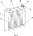
FIG. 2 is another schematic diagram of a filtering device for killing pathogenic microorganisms using deep ultraviolet laser according to an embodiment of the present disclosure; -
FIG. 3 is a schematic diagram of a path of forming a deep ultraviolet laser net by deep ultraviolet laser inFIG. 1 according to an embodiment of the present disclosure; -
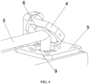
FIG. 4 is a partial enlarged view of detail A inFIG. 1 according to an embodiment of the present disclosure. - In the drawings: 1-main body; 2-deep ultraviolet laser apparatus; 3-deep ultraviolet laser; 4-adjusting part; 5-support; 6-first reflector; 7-reflector set; 8-deep ultraviolet laser net; 9-light inlet aperture.
- To make the objective, features and advantages of the present disclosure more apparently understandable, the following describes the specific embodiments of the present disclosure in detail with reference to the accompanying drawings. Many specific details are set forth in the following description to facilitate a full understanding of the present disclosure. However, the present disclosure can be implemented in many other ways than those described herein, and those skilled in the art may make similar modifications without departing from the scope of the claims.
- In the description of the present disclosure, it should be understood that the orientation or positional relationship indicated by terms "center", "longitudinal", "transverse", "length", "width", "thickness", "upper", "lower", "front", "back", "left", "right", "vertical", "horizontal", "top", "bottom", "inside", "outside", "clockwise", "counterclockwise", "axial", "radial", "circumferential" is based on the orientation or positional relationship shown in the drawings only for convenience of description of the present disclosure and simplification of description rather than indicating or implying that the device or element referred to must have a particular orientation, be constructed and operate in a particular orientation, and thus are not to be construed as a limitation of the present disclosure.
- Furthermore, the terms "first" and "second" are used for descriptive purposes only and are not to be construed as indicating or implying relative importance or implying a number of the indicated technical features. As such, the features limited to "first" and "second" may explicitly or implicitly include at least one of those features. In the description of the present disclosure, "a plurality of" means at least two, for example, two, three, and the like, unless expressly specified otherwise.
- In the present disclosure, unless expressly specified and defined otherwise, the terms "mounted," "connected," "connection," "fixed" and the like should be understood broadly, for example, may be fixed connection, detachable connection, or integral connection; may be mechanical connection or electrical connection; may be direct connection or indirect connection via an intermediate medium; and may also be internal communication of two elements or an interaction relationship between the two elements, unless expressly defined otherwise. The specific meanings of the above terms in the present disclosure may be understood on a case-by-case basis for those of ordinary skill in the art.
- In the present disclosure, unless expressly specified and defined otherwise, the first feature "on" or "under" the second feature may be that the first feature is in direct contact with the second feature, or the first feature is in indirect contact with the second feature via an intermediate medium. Moreover, the first feature "over", "above" and "upside" the second feature may be that the first feature is directly above or diagonally above the second feature, or simply indicates that the first feature is higher than the second feature in a horizontal height. The first feature "under", "below" and "beneath" the second feature may be that the first feature is directly below or diagonally below the second feature, or simply indicates that the first feature is lower than the second feature in a horizontal height.
- It is noted that when the element is referred to as being "fixed to" or "arranged on" another element, it may be directly on another element or an intervening element may also be present. When one element is regarded to as being "connected to" another element, it may be directly connected to another element or an intervening element may be present at the same time. The terms "vertical", "horizontal", "upper", "lower", "left", "right" used herein and similar expressions thereof are for illustrative purposes only and are not meant to be the only embodiments.
- To make the objective, features and advantages of the present disclosure more apparently understandable, the following further describes the present disclosure in detail with reference to the accompanying drawings and specific embodiments.
- As shown in
FIG. 1 to FIG. 4 , the embodiment of the present disclosure provides a filtering device for killing pathogenic microorganisms using deep ultraviolet laser, which includes amain body 1 and a deep ultraviolet laser module. - In an embodiment, the
main body 1 is used for accommodating gas having pathogenic microorganisms. In an embodiment, an inner surface of themain body 1 is of a topological shape. The topological shape means that the metric properties such as length, size, area and volume of the shape are not considered, that is, the topological shape can be understood as an arbitrary shape. The topological shape includes, for example, but is not limited to a quad, a pentagon, a square, a rectangle, a circle, a hexagon, a decagon and the like. That is, the shape of the inner surface of themain body 1 includes, for example, but is not limited to the circle, the rectangle, the square and the like. - In an embodiment, the deep ultraviolet laser module is connected to the
main body 1 and is used for totally reflecting thedeep ultraviolet laser 3 for multiple times to form a dense and regular deepultraviolet laser net 8, such that the gas is filtered in the dense and regular deepultraviolet laser net 8 to achieve the killing of the pathogenic microorganisms in the gas. The deepultraviolet laser net 8 refers to a net formed by totally reflecting laser beams for multiple times. The total reflection refers to a phenomenon that the light is totally reflected back to an original medium when the light emits from an optically denser medium to an interface of an optically thinner medium. In an embodiment, a propagation direction of thedeep ultraviolet laser 3 can be controlled in a total reflection manner, such that higher deep ultraviolet laser energy can be retained while thedeep ultraviolet laser 3 is evenly distributed inside themain body 1. In an embodiment, the dense and regular deepultraviolet laser net 8 refers to a net formed by thedeep ultraviolet laser 3 along a regular reflection path, under the effect of total reflection. - In an embodiment, the deep ultraviolet laser module includes a deep
ultraviolet laser apparatus 2 and a reflection adjusting assembly. The deepultraviolet laser apparatus 2 is connected to themain body 1, and the reflection adjusting assembly is used for adjusting the density of the deepultraviolet laser net 8. - In an embodiment, the reflection adjusting assembly includes a
first reflector 6, a reflector set 7, an adjustingpart 4, and asupport 5. The adjustingpart 4 is rotatably connected to thesupport 5. Thefirst reflector 6 is installed on the adjustingpart 4 and used for reflecting thedeep ultraviolet laser 3 into themain body 1. The reflector set 7 is arranged inside themain body 1 and used for totally reflecting thedeep ultraviolet laser 3 reflected into the main body for multiple times to form a dense and regular deep ultraviolet laser beam net. - In an embodiment, the reflector set 7 includes multiple second reflectors arranged on the inner surface of the
main body 1. When the number of the multiple second reflectors is an odd number, the odd number of second reflectors are distributed at different positions of the inner surface of themain body 1 according to the density of deepultraviolet laser net 8. When the number of the multiple second reflectors is an even number, the even number of second reflectors are evenly distributed on the inner surface of the main body in a pairwise manner. Further, the reflector set 7 may includes second reflector(s) completely covering the inner surface of themain body 1. In an embodiment, the reflector set 7 includes two second reflectors opposite to each other, the two opposite second reflectors are arranged at the inner surface of themain body 1. For example, in an embodiment, one of the two second reflectors is arranged at one side of the inner surface of the main body which is corresponding to thelight inlet aperture 9, and the other one of the two second reflectors is arranged at the opposite side of the inner surface of themain body 1. In an embodiment, the reflector set 7 is a second reflector completely covering the inner surface of themain body 1. In an embodiment, when the reflector set 7 is the second reflector completely covering the inner surface of themain body 1, the formed deepultraviolet laser net 8 is the laser beam net which is diffused from the center of the inner surface of the main body to the periphery of the inner surface of the main body, such that the formed deep ultraviolet laser beam net is denser and more regular to further enhance the disinfection and sterilization effect. - In an embodiment, each lens of the reflector set 7 is provided with a reflective film. That is, all the lenses of the reflector set 7 are coated with reflective films, and the reflective films are not particularly limited and are commonly used in the art.
- In an embodiment, the
main body 1 is provided with alight inlet aperture 9 which is used for transmitting the laser into themain body 1. - In an embodiment, the
light inlet aperture 9 includes one of an annular closed aperture or a polygonal closed aperture. For example, in an embodiment, thelight inlet aperture 9 may be an annular closed aperture, or a hexagonal closed aperture and the like. - In an embodiment, the deep
ultraviolet laser apparatus 2 has a wavelength ranging between 200 nm and 400 nm. In an embodiment, the deep ultraviolet laser has high energy per unit area. The wavelength of the deepultraviolet laser apparatus 2 can be, for example, but not limited to, 257 nm. For example, the wavelength can be 266 nm, and the like. In an embodiment, the deepultraviolet laser net 8 is completely filled inside themain body 1. - In an embodiment, the deep
ultraviolet laser apparatus 2 outputs thedeep ultraviolet laser 3. Thefirst reflector 6 is adjusted by rotating the adjustingpart 4, such that the output deepultraviolet laser 3 enters themain body 1 through thelight inlet aperture 9 after being reflected by thefirst reflector 6. Then, the dense and regular deepultraviolet laser net 8 is formed by totally reflecting laser to intercross multiple times by the reflector set 7 in themain body 1. - In an embodiment, the density of the deep
ultraviolet laser net 8 is controlled by adjusting an angle of thefirst reflector 6 and adjusting the area of the inner surface of the main body covered by the reflector set 7. In general, the larger the area of the inner surface of themain body 1 covered by the reflector set 7, the denser and more regular of the deepultraviolet laser net 8, so the disinfection and sterilization effect is more stronger. For example, in an embodiment, the angle of thefirst reflector 6 is adjusted by adjusting (e.g., rotating) the adjustingpart 4 to adjust an incident angle of the laser entering themain body 1, thus controlling the density of the deepultraviolet laser net 8. The angle of thefirst reflector 6 is an included angle between thesupport 5 and thefirst reflector 6, and the angle of thefirst reflector 6 is adjusted by rotating the adjustingpart 4. In an embodiment, the angle of thefirst reflector 6 includes an angle between 40 degrees and 50 degrees. When the angle of thefirst reflector 6 ranges between 40 degrees and 50 degrees, the formed deepultraviolet laser net 8 is denser, thus the disinfection and sterilization effect is greatly enhanced. - In an embodiment, the deep
ultraviolet laser apparatus 2 outputs thedeep ultraviolet laser 3, and thedeep ultraviolet laser 3 has a wavelength of 257 nm. The adjustingpart 4 is rotated so that the angle of thefirst reflector 6 is between 40 degrees and 50 degrees, and the output deepultraviolet laser 3 enters themain body 1 through thelight inlet aperture 9 after being reflected by thefirst reflector 6. The reflector set 7 includes two second reflectors which are arranged on the inner surface of themain body 1 and opposite to each other. One of the second reflectors is arranged on one side of the inner surface of themain body 1 which is corresponding to thelight inlet aperture 9, and the other one of the second reflectors is arranged on the opposite side of the inner surface of themain body 1. Then, the input laser is intercrossed multiple times via the total reflection of the two second reflectors opposite to each other, so as to form the dense and regular deepultraviolet laser net 8, such that the gas having the pathogenic microorganisms is filtered in the dense and regular deepultraviolet laser net 8, and the pathogenic microorganisms in the gas are killed. The device greatly improves the disinfection and sterilization efficiency and enhances the disinfection and sterilization effect. Moreover, the device is simple and convenient to use, easy to replace, low in manufacturing cost, and free of generating secondary pollutants. - In an embodiment, the deep
ultraviolet laser apparatus 2 outputs thedeep ultraviolet laser 3, and thedeep ultraviolet laser 3 has a wavelength of 257 nm; the adjustingpart 4 is rotated so that the angle of thefirst reflector 6 is between 40 degrees and 50 degrees, and the output deepultraviolet laser 3 enters themain body 1 through thelight inlet aperture 9 after being reflected by thefirst reflector 6. The reflector set 7 is a second reflector completely covering the inner surface of themain body 1. That is, the inner surface of themain body 1 is provided with a layer of second reflector. Then, the input laser is intercrossed multiple times via the total reflection of two opposite parts of the second reflector to form the dense and regular deepultraviolet laser net 8, such that the gas having the pathogenic microorganisms is filtered in the dense and regular deepultraviolet laser net 8, and the pathogenic microorganisms in the gas are killed. The device greatly improves the disinfection and sterilization efficiency and further enhances the disinfection and sterilization effect. Moreover, the device is simple and convenient to use, easy to replace, low in manufacturing cost, and free of generating secondary pollutants. - The various technical features of the embodiments above may be combined arbitrarily. For simplicity of description, all possible combinations of the various technical features in the embodiments above are not described. The application field of the technical solution is not specially specified, and for example, the device can be arranged in a traditional air conditioner or an air filter element.
- It should be noted that, for those skilled in the art, it is apparent that the present disclosure is not limited to the details of the exemplary embodiments above, and that the present disclosure may be embodied in other specific forms without departing from the scope of the claims. Therefore, the embodiments should be regarded as illustrative rather than restrictive in either case. The scope of the present disclosure is defined by the appended claims rather than by the foregoing description, and all changes falling within the meaning and scope of equivalency of the claims are therefore intended to be embraced therein, any reference numerals in the claims shall not be construed as limiting the claims involved.
- Specific examples are used for illustration of the principles and implementation of the present disclosure. The description of the embodiments is merely used to help illustrate the method and its core principles of the present disclosure. In addition, a person of ordinary skill in the art can make various modifications in terms of specific implementation and scope of application in accordance with the teachings of the present disclosure, without departing from the scope of the claims.
Claims (6)
- A filtering device for killing pathogenic microorganisms using deep ultraviolet laser, comprising:a main body (1) for accommodating gas having the pathogenic microorganisms; anda deep ultraviolet laser (3) module connected to the main body (1) and configured for totally reflecting the deep ultraviolet laser (3) for a plurality of times to form a deep ultraviolet laser net (8) in the main body (1), wherein the deep ultraviolet laser (3) module comprises a deep ultraviolet laser apparatus (2) and a reflection adjusting assembly, wherein the deep ultraviolet laser apparatus (2) is connected to the main body (1), and the reflection adjusting assembly arranged at a light-emitting side of the deep ultraviolet laser apparatus (2) is configured for adjusting a density of the deep ultraviolet laser net (8); anda reflection adjusting assembly having a first reflector (6) and a reflector set (7) which is arranged inside the main body (1);characterized in thatthe reflection adjusting assembly further comprises an adjusting part (4) and a support (5); the adjusting part (4) is rotatably connected to the support (5); the first reflector (6) is installed on the adjusting part (4) and configured for reflecting the deep ultraviolet laser (3) from the light-emitting side of the deep ultraviolet laser apparatus (2) into the main body (1); the reflector set (7) is configured for totally reflecting the deep ultraviolet laser (3) reflected into the main body (1) by the first reflector (6) for a plurality of times to form the deep ultraviolet laser net (8),the reflector set (7) comprises at least one second reflector completely covering an inner surface of the main body (1), andthe inner surface of the main body (1) is of a circle shape.
- The filtering device according to claim 1, wherein the deep ultraviolet laser apparatus (2) has a wavelength ranging between 200 nm and 400 nm.
- The filtering device according to claim 1, wherein the adjusting part (4) is configured for adjusting an angle of the first reflector (6), and the angle of the first reflector (6) comprises an angle between 40 degrees and 50 degrees.
- The filtering device according to claim 1, wherein each lens of the reflector set (7) is provided with a reflective film.
- The filtering device according to claim 4, wherein the main body (1) is provided with a light inlet aperture, and the light inlet aperture is configured for transmitting the deep ultraviolet laser (3) into the main body (1).
- The filtering device according to claim 5, wherein the light inlet aperture comprises an annular aperture or a polygonal aperture.
Applications Claiming Priority (1)
| Application Number | Priority Date | Filing Date | Title |
|---|---|---|---|
| CN202210636259.XA CN115252867A (en) | 2022-06-07 | 2022-06-07 | Pathogenic microorganism killing and filtering device utilizing deep ultraviolet laser |
Publications (3)
| Publication Number | Publication Date |
|---|---|
| EP4289449A1 EP4289449A1 (en) | 2023-12-13 |
| EP4289449C0 EP4289449C0 (en) | 2025-06-04 |
| EP4289449B1 true EP4289449B1 (en) | 2025-06-04 |
Family
ID=83050139
Family Applications (1)
| Application Number | Title | Priority Date | Filing Date |
|---|---|---|---|
| EP22191739.6A Active EP4289449B1 (en) | 2022-06-07 | 2022-08-23 | Filtering device for killing pathogenic microorganisms using deep ultraviolet laser |
Country Status (6)
| Country | Link |
|---|---|
| US (1) | US12350389B2 (en) |
| EP (1) | EP4289449B1 (en) |
| JP (1) | JP7504489B2 (en) |
| KR (1) | KR102841224B1 (en) |
| CN (1) | CN115252867A (en) |
| HU (1) | HUE072088T2 (en) |
Families Citing this family (4)
| Publication number | Priority date | Publication date | Assignee | Title |
|---|---|---|---|---|
| CN115970039B (en) * | 2022-12-21 | 2023-09-01 | 广东国志激光技术有限公司 | Laser sterilization cavity, sterilization device and sterilization system |
| CN116036339A (en) * | 2023-01-10 | 2023-05-02 | 中国科学院上海光学精密机械研究所 | Deep ultraviolet laser air disinfection device |
| JP2024105158A (en) * | 2023-01-25 | 2024-08-06 | Next Innovation合同会社 | Ultraviolet Amplification Device |
| CN119386221B (en) * | 2024-11-15 | 2025-10-10 | 青岛北辰铭银机电设备有限公司 | A deep ultraviolet LED light source sterilization and disinfection equipment without negative pressure |
Family Cites Families (10)
| Publication number | Priority date | Publication date | Assignee | Title |
|---|---|---|---|---|
| JP2003260329A (en) | 2002-03-11 | 2003-09-16 | Sharp Corp | Radical generation device, substance removal device and air purification device |
| US20120168641A1 (en) * | 2010-09-08 | 2012-07-05 | Lizotte Todd E | Uv ptfe diffuser technology |
| JP2014004507A (en) | 2012-06-22 | 2014-01-16 | Ushio Inc | Fluid treatment apparatus |
| ES2819557T3 (en) | 2016-01-07 | 2021-04-16 | Mitsubishi Electric Corp | UV sterilizer and air conditioner using the same |
| CN111780278A (en) * | 2020-06-24 | 2020-10-16 | 佛山北科科技创新有限公司 | Ultraviolet laser disinfection channel |
| CN111895541B (en) | 2020-08-18 | 2021-05-18 | 华中科技大学 | Sterilizing device of central air conditioner |
| KR102602730B1 (en) * | 2020-11-19 | 2023-11-16 | 국방과학연구소 | Laser sterilization module and system |
| CN113425883A (en) * | 2021-07-28 | 2021-09-24 | 广东国志激光技术有限公司 | Air purification method by utilizing unstable resonator to reflect ultraviolet laser |
| CN114272425A (en) * | 2021-12-21 | 2022-04-05 | 广东国志激光技术有限公司 | Laser disinfection device for exhaust system of isolation transfer trolley |
| CN114552358A (en) * | 2022-02-28 | 2022-05-27 | 中国科学院半导体研究所 | Device for generating deep ultraviolet laser |
-
2022
- 2022-06-07 CN CN202210636259.XA patent/CN115252867A/en active Pending
- 2022-08-23 EP EP22191739.6A patent/EP4289449B1/en active Active
- 2022-08-23 HU HUE22191739A patent/HUE072088T2/en unknown
- 2022-08-25 JP JP2022134389A patent/JP7504489B2/en active Active
- 2022-09-07 US US17/939,495 patent/US12350389B2/en active Active
-
2023
- 2023-04-12 KR KR1020230048472A patent/KR102841224B1/en active Active
Also Published As
| Publication number | Publication date |
|---|---|
| US12350389B2 (en) | 2025-07-08 |
| JP7504489B2 (en) | 2024-06-24 |
| KR102841224B1 (en) | 2025-07-31 |
| JP2023179342A (en) | 2023-12-19 |
| EP4289449C0 (en) | 2025-06-04 |
| EP4289449A1 (en) | 2023-12-13 |
| KR20230168580A (en) | 2023-12-14 |
| US20230390435A1 (en) | 2023-12-07 |
| CN115252867A (en) | 2022-11-01 |
| HUE072088T2 (en) | 2025-10-28 |
Similar Documents
| Publication | Publication Date | Title |
|---|---|---|
| EP4289449A1 (en) | Filtering device for killing pathogenic microorganisms using deep ultraviolet laser | |
| JP6990335B1 (en) | Virus killing and sterilization equipment for central air conditioning | |
| US8585979B2 (en) | Enhanced photo-catalytic cells | |
| US20230293745A1 (en) | Inactivation device for bacteria and/or viruses | |
| WO2022230359A1 (en) | Ultraviolet light emission device, method for using ultraviolet light emission device, and ultraviolet light emission method | |
| CN113827749A (en) | A deep ultraviolet LED sterilization device | |
| CN111420108A (en) | Circulating air multi-directional ultraviolet irradiation disinfection system and disinfection device having the same | |
| CN111939304A (en) | A laser antivirus device based on beam shaping and reflex control | |
| CN213048381U (en) | Sterilizing lamp | |
| WO2022074944A1 (en) | Ultraviolet light irradiation device, use method for ultraviolet light irradiation device, and irradiation method of ultraviolet light | |
| JP7759546B2 (en) | Ultraviolet light irradiation device, method of using ultraviolet light irradiation device, and ultraviolet light irradiation method | |
| US11744913B2 (en) | Fluid conduit disinfector | |
| CN217385997U (en) | Light-collecting beam UVLED ultraviolet scanning device | |
| GB2593827A (en) | Visible and infrared light reflective air purification system and method thereof | |
| CN216061374U (en) | Deep ultraviolet LED sterilizing device | |
| CN215692928U (en) | Sterilization device, air cleaner and filtration system | |
| CN114452431A (en) | Ultraviolet-ultrasonic combined disinfection and sterilization device and method harmless to human body | |
| EP4460338A1 (en) | A radiation generating system comprising an optical arrangement for a far uv light source minimizing the impact of unfiltered undesired wavelengths | |
| CN113694240A (en) | Man-machine coexisting air virus inactivation device | |
| TWM624989U (en) | Lighting device with sterilization function | |
| CN221655276U (en) | A UVC sterilization module for air purifier | |
| CN111744047A (en) | A plate type sterilization system | |
| CN116036338A (en) | Air sterilization device | |
| CN213334696U (en) | LED sterilization and disinfection structure for air outlet of air conditioner fan | |
| CN119667833A (en) | 222nm far-ultraviolet light source and X-virus disinfection and epidemic prevention equipment special filter lens |
Legal Events
| Date | Code | Title | Description |
|---|---|---|---|
| PUAI | Public reference made under article 153(3) epc to a published international application that has entered the european phase |
Free format text: ORIGINAL CODE: 0009012 |
|
| STAA | Information on the status of an ep patent application or granted ep patent |
Free format text: STATUS: REQUEST FOR EXAMINATION WAS MADE |
|
| 17P | Request for examination filed |
Effective date: 20220823 |
|
| AK | Designated contracting states |
Kind code of ref document: A1 Designated state(s): AL AT BE BG CH CY CZ DE DK EE ES FI FR GB GR HR HU IE IS IT LI LT LU LV MC MK MT NL NO PL PT RO RS SE SI SK SM TR |
|
| STAA | Information on the status of an ep patent application or granted ep patent |
Free format text: STATUS: EXAMINATION IS IN PROGRESS |
|
| 17Q | First examination report despatched |
Effective date: 20240725 |
|
| GRAP | Despatch of communication of intention to grant a patent |
Free format text: ORIGINAL CODE: EPIDOSNIGR1 |
|
| STAA | Information on the status of an ep patent application or granted ep patent |
Free format text: STATUS: GRANT OF PATENT IS INTENDED |
|
| INTG | Intention to grant announced |
Effective date: 20250128 |
|
| GRAS | Grant fee paid |
Free format text: ORIGINAL CODE: EPIDOSNIGR3 |
|
| GRAA | (expected) grant |
Free format text: ORIGINAL CODE: 0009210 |
|
| STAA | Information on the status of an ep patent application or granted ep patent |
Free format text: STATUS: THE PATENT HAS BEEN GRANTED |
|
| AK | Designated contracting states |
Kind code of ref document: B1 Designated state(s): AL AT BE BG CH CY CZ DE DK EE ES FI FR GB GR HR HU IE IS IT LI LT LU LV MC MK MT NL NO PL PT RO RS SE SI SK SM TR |
|
| REG | Reference to a national code |
Ref country code: GB Ref legal event code: FG4D |
|
| REG | Reference to a national code |
Ref country code: CH Ref legal event code: EP |
|
| REG | Reference to a national code |
Ref country code: DE Ref legal event code: R096 Ref document number: 602022015399 Country of ref document: DE |
|
| REG | Reference to a national code |
Ref country code: IE Ref legal event code: FG4D |
|
| U01 | Request for unitary effect filed |
Effective date: 20250626 |
|
| U07 | Unitary effect registered |
Designated state(s): AT BE BG DE DK EE FI FR IT LT LU LV MT NL PT RO SE SI Effective date: 20250702 |
|
| PG25 | Lapsed in a contracting state [announced via postgrant information from national office to epo] |
Ref country code: ES Free format text: LAPSE BECAUSE OF FAILURE TO SUBMIT A TRANSLATION OF THE DESCRIPTION OR TO PAY THE FEE WITHIN THE PRESCRIBED TIME-LIMIT Effective date: 20250604 |
|
| PG25 | Lapsed in a contracting state [announced via postgrant information from national office to epo] |
Ref country code: NO Free format text: LAPSE BECAUSE OF FAILURE TO SUBMIT A TRANSLATION OF THE DESCRIPTION OR TO PAY THE FEE WITHIN THE PRESCRIBED TIME-LIMIT Effective date: 20250904 Ref country code: GR Free format text: LAPSE BECAUSE OF FAILURE TO SUBMIT A TRANSLATION OF THE DESCRIPTION OR TO PAY THE FEE WITHIN THE PRESCRIBED TIME-LIMIT Effective date: 20250905 |
|
| PG25 | Lapsed in a contracting state [announced via postgrant information from national office to epo] |
Ref country code: PL Free format text: LAPSE BECAUSE OF FAILURE TO SUBMIT A TRANSLATION OF THE DESCRIPTION OR TO PAY THE FEE WITHIN THE PRESCRIBED TIME-LIMIT Effective date: 20250604 |
|
| PGFP | Annual fee paid to national office [announced via postgrant information from national office to epo] |
Ref country code: HU Payment date: 20250903 Year of fee payment: 4 |
|
| PG25 | Lapsed in a contracting state [announced via postgrant information from national office to epo] |
Ref country code: HR Free format text: LAPSE BECAUSE OF FAILURE TO SUBMIT A TRANSLATION OF THE DESCRIPTION OR TO PAY THE FEE WITHIN THE PRESCRIBED TIME-LIMIT Effective date: 20250604 |
|
| PGFP | Annual fee paid to national office [announced via postgrant information from national office to epo] |
Ref country code: CH Payment date: 20250901 Year of fee payment: 4 |
|
| PG25 | Lapsed in a contracting state [announced via postgrant information from national office to epo] |
Ref country code: RS Free format text: LAPSE BECAUSE OF FAILURE TO SUBMIT A TRANSLATION OF THE DESCRIPTION OR TO PAY THE FEE WITHIN THE PRESCRIBED TIME-LIMIT Effective date: 20250904 |
|
| PGFP | Annual fee paid to national office [announced via postgrant information from national office to epo] |
Ref country code: IE Payment date: 20250821 Year of fee payment: 4 |
|
| REG | Reference to a national code |
Ref country code: HU Ref legal event code: AG4A Ref document number: E072088 Country of ref document: HU |
|
| U20 | Renewal fee for the european patent with unitary effect paid |
Year of fee payment: 4 Effective date: 20250929 |
|
| PG25 | Lapsed in a contracting state [announced via postgrant information from national office to epo] |
Ref country code: IS Free format text: LAPSE BECAUSE OF FAILURE TO SUBMIT A TRANSLATION OF THE DESCRIPTION OR TO PAY THE FEE WITHIN THE PRESCRIBED TIME-LIMIT Effective date: 20251004 |
|
| PG25 | Lapsed in a contracting state [announced via postgrant information from national office to epo] |
Ref country code: SM Free format text: LAPSE BECAUSE OF FAILURE TO SUBMIT A TRANSLATION OF THE DESCRIPTION OR TO PAY THE FEE WITHIN THE PRESCRIBED TIME-LIMIT Effective date: 20250604 |
|
| PG25 | Lapsed in a contracting state [announced via postgrant information from national office to epo] |
Ref country code: CZ Free format text: LAPSE BECAUSE OF FAILURE TO SUBMIT A TRANSLATION OF THE DESCRIPTION OR TO PAY THE FEE WITHIN THE PRESCRIBED TIME-LIMIT Effective date: 20250604 |
|
| PG25 | Lapsed in a contracting state [announced via postgrant information from national office to epo] |
Ref country code: SK Free format text: LAPSE BECAUSE OF FAILURE TO SUBMIT A TRANSLATION OF THE DESCRIPTION OR TO PAY THE FEE WITHIN THE PRESCRIBED TIME-LIMIT Effective date: 20250604 |
|
| PG25 | Lapsed in a contracting state [announced via postgrant information from national office to epo] |
Ref country code: MC Free format text: LAPSE BECAUSE OF FAILURE TO SUBMIT A TRANSLATION OF THE DESCRIPTION OR TO PAY THE FEE WITHIN THE PRESCRIBED TIME-LIMIT Effective date: 20250604 |
|
| PLBE | No opposition filed within time limit |
Free format text: ORIGINAL CODE: 0009261 |
|
| STAA | Information on the status of an ep patent application or granted ep patent |
Free format text: STATUS: NO OPPOSITION FILED WITHIN TIME LIMIT |
|
| REG | Reference to a national code |
Ref country code: CH Ref legal event code: L10 Free format text: ST27 STATUS EVENT CODE: U-0-0-L10-L00 (AS PROVIDED BY THE NATIONAL OFFICE) Effective date: 20260416 |
|
| 26N | No opposition filed |
Effective date: 20260305 |