EP4289300A1 - Atomizer, resistive slurry, heating assembly, and aerosol generation device - Google Patents
Atomizer, resistive slurry, heating assembly, and aerosol generation device Download PDFInfo
- Publication number
- EP4289300A1 EP4289300A1 EP22748939.0A EP22748939A EP4289300A1 EP 4289300 A1 EP4289300 A1 EP 4289300A1 EP 22748939 A EP22748939 A EP 22748939A EP 4289300 A1 EP4289300 A1 EP 4289300A1
- Authority
- EP
- European Patent Office
- Prior art keywords
- resistance heating
- iron
- trajectory
- vaporizer
- silicon alloy
- Prior art date
- Legal status (The legal status is an assumption and is not a legal conclusion. Google has not performed a legal analysis and makes no representation as to the accuracy of the status listed.)
- Pending
Links
Images




Classifications
-
- A—HUMAN NECESSITIES
- A24—TOBACCO; CIGARS; CIGARETTES; SIMULATED SMOKING DEVICES; SMOKERS' REQUISITES
- A24F—SMOKERS' REQUISITES; MATCH BOXES; SIMULATED SMOKING DEVICES
- A24F40/00—Electrically operated smoking devices; Component parts thereof; Manufacture thereof; Maintenance or testing thereof; Charging means specially adapted therefor
- A24F40/10—Devices using liquid inhalable precursors
-
- A—HUMAN NECESSITIES
- A24—TOBACCO; CIGARS; CIGARETTES; SIMULATED SMOKING DEVICES; SMOKERS' REQUISITES
- A24F—SMOKERS' REQUISITES; MATCH BOXES; SIMULATED SMOKING DEVICES
- A24F40/00—Electrically operated smoking devices; Component parts thereof; Manufacture thereof; Maintenance or testing thereof; Charging means specially adapted therefor
- A24F40/40—Constructional details, e.g. connection of cartridges and battery parts
-
- A—HUMAN NECESSITIES
- A24—TOBACCO; CIGARS; CIGARETTES; SIMULATED SMOKING DEVICES; SMOKERS' REQUISITES
- A24F—SMOKERS' REQUISITES; MATCH BOXES; SIMULATED SMOKING DEVICES
- A24F40/00—Electrically operated smoking devices; Component parts thereof; Manufacture thereof; Maintenance or testing thereof; Charging means specially adapted therefor
- A24F40/40—Constructional details, e.g. connection of cartridges and battery parts
- A24F40/42—Cartridges or containers for inhalable precursors
-
- A—HUMAN NECESSITIES
- A24—TOBACCO; CIGARS; CIGARETTES; SIMULATED SMOKING DEVICES; SMOKERS' REQUISITES
- A24F—SMOKERS' REQUISITES; MATCH BOXES; SIMULATED SMOKING DEVICES
- A24F40/00—Electrically operated smoking devices; Component parts thereof; Manufacture thereof; Maintenance or testing thereof; Charging means specially adapted therefor
- A24F40/40—Constructional details, e.g. connection of cartridges and battery parts
- A24F40/44—Wicks
-
- A—HUMAN NECESSITIES
- A24—TOBACCO; CIGARS; CIGARETTES; SIMULATED SMOKING DEVICES; SMOKERS' REQUISITES
- A24F—SMOKERS' REQUISITES; MATCH BOXES; SIMULATED SMOKING DEVICES
- A24F40/00—Electrically operated smoking devices; Component parts thereof; Manufacture thereof; Maintenance or testing thereof; Charging means specially adapted therefor
- A24F40/40—Constructional details, e.g. connection of cartridges and battery parts
- A24F40/46—Shape or structure of electric heating means
-
- H—ELECTRICITY
- H05—ELECTRIC TECHNIQUES NOT OTHERWISE PROVIDED FOR
- H05B—ELECTRIC HEATING; ELECTRIC LIGHT SOURCES NOT OTHERWISE PROVIDED FOR; CIRCUIT ARRANGEMENTS FOR ELECTRIC LIGHT SOURCES, IN GENERAL
- H05B3/00—Ohmic-resistance heating
- H05B3/02—Details
- H05B3/04—Waterproof or air-tight seals for heaters
-
- H—ELECTRICITY
- H05—ELECTRIC TECHNIQUES NOT OTHERWISE PROVIDED FOR
- H05B—ELECTRIC HEATING; ELECTRIC LIGHT SOURCES NOT OTHERWISE PROVIDED FOR; CIRCUIT ARRANGEMENTS FOR ELECTRIC LIGHT SOURCES, IN GENERAL
- H05B3/00—Ohmic-resistance heating
- H05B3/10—Heating elements characterised by the composition or nature of the materials or by the arrangement of the conductor
- H05B3/12—Heating elements characterised by the composition or nature of the materials or by the arrangement of the conductor characterised by the composition or nature of the conductive material
- H05B3/14—Heating elements characterised by the composition or nature of the materials or by the arrangement of the conductor characterised by the composition or nature of the conductive material the material being non-metallic
- H05B3/148—Silicon, e.g. silicon carbide, magnesium silicide, heating transistors or diodes
-
- H—ELECTRICITY
- H05—ELECTRIC TECHNIQUES NOT OTHERWISE PROVIDED FOR
- H05B—ELECTRIC HEATING; ELECTRIC LIGHT SOURCES NOT OTHERWISE PROVIDED FOR; CIRCUIT ARRANGEMENTS FOR ELECTRIC LIGHT SOURCES, IN GENERAL
- H05B3/00—Ohmic-resistance heating
- H05B3/20—Heating elements having extended surface area substantially in a two-dimensional [2D] plane, e.g. plate-heater
- H05B3/22—Heating elements having extended surface area substantially in a two-dimensional [2D] plane, e.g. plate-heater non-flexible
- H05B3/26—Heating elements having extended surface area substantially in a two-dimensional [2D] plane, e.g. plate-heater non-flexible heating conductor mounted on insulating base
- H05B3/265—Heating elements having extended surface area substantially in a two-dimensional [2D] plane, e.g. plate-heater non-flexible heating conductor mounted on insulating base the insulating base being an inorganic material, e.g. ceramic
-
- A—HUMAN NECESSITIES
- A24—TOBACCO; CIGARS; CIGARETTES; SIMULATED SMOKING DEVICES; SMOKERS' REQUISITES
- A24F—SMOKERS' REQUISITES; MATCH BOXES; SIMULATED SMOKING DEVICES
- A24F40/00—Electrically operated smoking devices; Component parts thereof; Manufacture thereof; Maintenance or testing thereof; Charging means specially adapted therefor
- A24F40/70—Manufacture
-
- H—ELECTRICITY
- H05—ELECTRIC TECHNIQUES NOT OTHERWISE PROVIDED FOR
- H05B—ELECTRIC HEATING; ELECTRIC LIGHT SOURCES NOT OTHERWISE PROVIDED FOR; CIRCUIT ARRANGEMENTS FOR ELECTRIC LIGHT SOURCES, IN GENERAL
- H05B2203/00—Aspects relating to Ohmic resistive heating covered by group H05B3/00
- H05B2203/013—Heaters using resistive films or coatings
-
- H—ELECTRICITY
- H05—ELECTRIC TECHNIQUES NOT OTHERWISE PROVIDED FOR
- H05B—ELECTRIC HEATING; ELECTRIC LIGHT SOURCES NOT OTHERWISE PROVIDED FOR; CIRCUIT ARRANGEMENTS FOR ELECTRIC LIGHT SOURCES, IN GENERAL
- H05B2203/00—Aspects relating to Ohmic resistive heating covered by group H05B3/00
- H05B2203/017—Manufacturing methods or apparatus for heaters
-
- H—ELECTRICITY
- H05—ELECTRIC TECHNIQUES NOT OTHERWISE PROVIDED FOR
- H05B—ELECTRIC HEATING; ELECTRIC LIGHT SOURCES NOT OTHERWISE PROVIDED FOR; CIRCUIT ARRANGEMENTS FOR ELECTRIC LIGHT SOURCES, IN GENERAL
- H05B2203/00—Aspects relating to Ohmic resistive heating covered by group H05B3/00
- H05B2203/021—Heaters specially adapted for heating liquids
-
- H—ELECTRICITY
- H05—ELECTRIC TECHNIQUES NOT OTHERWISE PROVIDED FOR
- H05B—ELECTRIC HEATING; ELECTRIC LIGHT SOURCES NOT OTHERWISE PROVIDED FOR; CIRCUIT ARRANGEMENTS FOR ELECTRIC LIGHT SOURCES, IN GENERAL
- H05B2203/00—Aspects relating to Ohmic resistive heating covered by group H05B3/00
- H05B2203/022—Heaters specially adapted for heating gaseous material
Definitions
- Embodiments of this application relate to the technical field of aerosol generation devices, and in particular, to a vaporizer, a resistor paste, a heating assembly and an aerosol generation device.
- Tobacco products e.g., cigarettes, cigars, etc.
- Tobacco products burn tobacco in a using process to generate tobacco smoke. Attempts are made to replace these tobacco-burning products by manufacturing products that release compounds without burning.
- vaporization devices These devices usually contain liquid, and the liquid is heated to be vaporized, so as to generate an inhalable vapor or aerosol.
- the liquid may contain nicotine, and/or aromatics, and/or aerosol generation substances (e.g., glycerin).
- a known vaporization device adopts a heating assembly to vaporize liquid, the heating assembly includes a porous base body sucking the liquid through capillary infiltration, and a resistance heating trajectory formed on the porous base body, and the liquid sucked by the porous base body is heated and vaporized by the resistance heating trajectory to generate an aerosol.
- the above resistance heating trajectory is usually prepared from nickel, chromium, tungsten, etc., and thus can be subjected to temperature measurement through a resistance temperature coefficient while heating. There is heavy metal pollution during use.
- a vaporizer used for vaporizing a liquid substrate to generate an aerosol for inhaling, and including:
- the resistance heating trajectory with the iron-silicon alloy as a functional phase is adopted to heat and vaporize the liquid substrate in the porous body to generate the aerosol, which not only has a suitable resistance temperature coefficient but also does not contain heavy metals.
- the resistance heating trajectory has a resistance temperature coefficient of from 900 to 3000 ppm/°C.
- a mass percentage of silicon in the iron-silicon alloy of the resistance heating trajectory ranges from 3% to 15%.
- the resistance heating trajectory does not contain any one of nickel, chromium or tungsten.
- a mass percentage of the iron-silicon alloy in the resistance heating trajectory ranges from 80% to 95%.
- the resistance heating trajectory further includes a glass phase component, the glass phase component including at least one of SiO 2 , Al 2 O 3 , MgO, CaO or B 2 O 3 .
- a heating assembly including: an electrical insulation base body, and a resistance heating trajectory formed on the electrical insulation base body, the resistance heating trajectory including an iron-silicon alloy.
- the electric insulation base body includes a porous body. More preferably, the porous body includes a porous ceramic body.
- a resistor paste including:
- the resistor paste includes: 70 to 90 wt% of the iron-silicon alloy, 4 to 14 wt% of the glass phase, and 5 to 20 wt% of the liquid organic auxiliary.
- the glass phase component includes at least one of SiO 2 , Al 2 O 3 , MgO, CaO or B 2 O 3 .
- the resistor paste further includes a pore-forming agent. More preferably, a mass percentage of the pore-forming agent in the resistor paste is less than 1 wt%.
- an aerosol generation device including a vaporizer vaporizing a liquid substrate to generate an aerosol, and a power supply assembly supplying power to the vaporizer, the vaporizer includes the vaporizer described above.
- an aerosol generation device including:
- the aerosol generation device includes a vaporizer 100 storing a liquid substrate and vaporizing it to generate an aerosol, and a power supply assembly 200 supplying power to the vaporizer 100.
- the power supply assembly 200 includes a receiving cavity 270 provided at an end in a length direction and used for receiving and accommodating at least part of the vaporizer 100.
- the power supply assembly 200 is electrically connected with the vaporizer 100 to supply power to the vaporizer 100.
- the vaporizer 100 can be removed from the receiving cavity 270 for easy replacement and independent storage.
- the vaporizer 100 includes: a liquid storage cavity 12 used for storing a liquid substrate, and a heating assembly 30 sucking the liquid substrate and heating and vaporizing the liquid substrate to generate an aerosol.
- FIG. 2 shows a schematic structural diagram of an embodiment of the vaporizer 100 in FIG. 1 , and the vaporizer 100 includes:
- the specific structure of the heating assembly 30 includes:
- the porous body 31 can further have a flat plate shape, a concave shape with an upper surface facing the liquid storage cavity 12 provided with a cavity, an arched shape with one side of the liquid storage cavity 12 provided with an arched structure, etc.
- the resistance heating trajectory 32 is a patterned trajectory.
- the resistance heating trajectory 32 is formed in a stamped or printed manner.
- the resistance heating trajectory 32 is in a flat shape.
- the resistance heating trajectory 32 is a trajectory extending in a manner of meandering, detouring, etc.
- the resistance heating trajectory 32 has a thickness of 60 to 100 ⁇ m.
- the electrode column 21 After assembly, the electrode column 21 abuts against two ends of the resistance heating trajectory 32 to form a conductive connection to supply power to the resistance heating trajectory 32.
- resistor paste for preparing the above resistance heating trajectory 32 including:
- liquid organic auxiliary in an implementation:
- the resistor paste includes the following components in percentage by mass: 70% to 90% of the iron-silicon alloy powder, 4% to 14% of the glass phase, and 5% to 20% of the liquid organic auxiliary.
- the iron-silicon alloy powder and/or a powder of the glass phase added in the resistor paste as a particle size of between 0.1 and 200 ⁇ m, which is advantageous to uniform dispersion of the powders.
- the particle size within the above range can be obtained by water quenching and ball milling of raw materials.
- the resistor paste can further include: in percentage by mass, less than 1% of a pore-forming agent.
- the pore-forming agent can adopt cellulose, wood fibers, short carbon fibers, etc. In a sintering process, the pore-forming agent is burned or decomposed into a gas to escape, thus forming pores.
- a method for preparing a heating assembly 30 from the above resistor paste including:
- a liquid organic auxiliary and a pore-forming agent will decompose and evaporate, and do not remain in the resistance heating trajectory 32.
- sintering or heat treatment is conducted in a sintering furnace device and the like at a temperature of from 900 to 1200°C.
- the sintering time is controlled between 20 to 90 min.
- a mass percentage of an iron-silicon alloy phase in the resistance heating trajectory 32 after sintering ranges from 80% to 95%.
- the sintering process is conducted in a reducing atmosphere.
- the resistance heating trajectory 32 formed after sintering there are only a cured glass phase and the functional phase of the iron-silicon alloy, and during power supply, a liquid substrate sucked in the porous body 31 can be heated to generate an aerosol.
- a resistance temperature coefficient of the finally prepared resistance heating trajectory 32 is adjustable within an expected range, such as 900 to 3000 ppm/°C.
- the temperature of the resistance heating trajectory 32 can be determined by detecting the resistance temperature coefficient of the resistance heating trajectory 32.
- the prepared heating assembly is illustrated below with examples and results through specific embodiments.
- Embodiment 3 adopts the same method steps as Embodiment 1. In preparation of a resistor paste, 71 wt% of a functional phase of an iron-silicon alloy powder and 14 wt% of a glass phase are used for preparing a heating assembly of Embodiment 3.
- Embodiment 4 adopts the same method steps as Embodiment 2.
- the content of silicon in the functional phase of the iron-silicon alloy powder is adjusted to 12 wt% to prepare a heating assembly of Embodiment 3.
- Embodiment 5 adopts the same method steps as Embodiment 1.
- preparation of a resistor paste 88 wt% of an iron-silicon alloy powder, 5 wt% of a glass phase, and 7 wt% of a liquid organic auxiliary are used; wherein, the content of silicon in the functional phase of the iron-silicon alloy powder is 3.5 wt%; and a heating assembly of Embodiment 5 is prepared according to the above steps.
- the glass phase provides part of silicon oxide, thus the content of the silicon element at the analysis site is greater than the content of silicon described in the functional phase, but the functions are still provided by the iron-silicon alloy.
- the functional element components in a measured area are all iron and silicon.
- a vapor generation device with a structure shown in FIG. 4 , including:
Landscapes
- Chemical & Material Sciences (AREA)
- Engineering & Computer Science (AREA)
- Ceramic Engineering (AREA)
- Resistance Heating (AREA)
- Nozzles (AREA)
Abstract
Description
- This application claims the priority of the prior application No.
2021101756800 filed to the China National Intellectual Property Administration on February 6, 2021 - Embodiments of this application relate to the technical field of aerosol generation devices, and in particular, to a vaporizer, a resistor paste, a heating assembly and an aerosol generation device.
- Tobacco products (e.g., cigarettes, cigars, etc.) burn tobacco in a using process to generate tobacco smoke. Attempts are made to replace these tobacco-burning products by manufacturing products that release compounds without burning.
- Examples of such products are vaporization devices. These devices usually contain liquid, and the liquid is heated to be vaporized, so as to generate an inhalable vapor or aerosol. The liquid may contain nicotine, and/or aromatics, and/or aerosol generation substances (e.g., glycerin). A known vaporization device adopts a heating assembly to vaporize liquid, the heating assembly includes a porous base body sucking the liquid through capillary infiltration, and a resistance heating trajectory formed on the porous base body, and the liquid sucked by the porous base body is heated and vaporized by the resistance heating trajectory to generate an aerosol. The above resistance heating trajectory is usually prepared from nickel, chromium, tungsten, etc., and thus can be subjected to temperature measurement through a resistance temperature coefficient while heating. There is heavy metal pollution during use.
- Provided in an embodiment of this application is a vaporizer, used for vaporizing a liquid substrate to generate an aerosol for inhaling, and including:
- a liquid storage cavity, used for storing the liquid substrate;
- a porous body, being in fluid communication with the liquid storage cavity to suck the liquid substrate, the porous body including a vaporization face; and
- a resistance heating trajectory, formed on the vaporization face and used for heating at least part of the liquid substrate in the porous body to generate the aerosol, the resistance heating trajectory including an iron-silicon alloy.
- According to the above vaporizer, the resistance heating trajectory with the iron-silicon alloy as a functional phase is adopted to heat and vaporize the liquid substrate in the porous body to generate the aerosol, which not only has a suitable resistance temperature coefficient but also does not contain heavy metals.
- In a preferred implementation, the resistance heating trajectory has a resistance temperature coefficient of from 900 to 3000 ppm/°C.
- In a preferred implementation, a mass percentage of silicon in the iron-silicon alloy of the resistance heating trajectory ranges from 3% to 15%.
- In a preferred implementation, the resistance heating trajectory does not contain any one of nickel, chromium or tungsten.
- In a preferred implementation, a mass percentage of the iron-silicon alloy in the resistance heating trajectory ranges from 80% to 95%.
- In a preferred implementation, the resistance heating trajectory further includes a glass phase component, the glass phase component including at least one of SiO2, Al2O3, MgO, CaO or B2O3.
- Further provided in another embodiment of this application is a heating assembly, including:
an electrical insulation base body, and a resistance heating trajectory formed on the electrical insulation base body, the resistance heating trajectory including an iron-silicon alloy. - In a preferred implementation, the electric insulation base body includes a porous body. More preferably, the porous body includes a porous ceramic body.
- Further provided in yet another embodiment of this application is a resistor paste, including:
- an iron-silicon alloy;
- a glass phase component; and
- a liquid organic auxiliary, the liquid organic auxiliary including at least an organic solvent.
- In a preferred implementation, the resistor paste includes: 70 to 90 wt% of the iron-silicon alloy, 4 to 14 wt% of the glass phase, and 5 to 20 wt% of the liquid organic auxiliary.
- In a preferred implementation, the glass phase component includes at least one of SiO2, Al2O3, MgO, CaO or B2O3.
- In a preferred implementation, the resistor paste further includes a pore-forming agent. More preferably, a mass percentage of the pore-forming agent in the resistor paste is less than 1 wt%.
- Further provided in still another embodiment of this application is an aerosol generation device, including a vaporizer vaporizing a liquid substrate to generate an aerosol, and a power supply assembly supplying power to the vaporizer, the vaporizer includes the vaporizer described above.
- Further provided in still yet another embodiment of this application is an aerosol generation device, including:
- a chamber, configured to receive an aerosol generation product; and
- a resistance heater, used for heating the aerosol generation product, the resistance heater including an electrical insulation substrate, and a resistance heating trajectory formed on the electrical insulation substrate, the resistance heating trajectory including an iron-silicon alloy.
- The objective implementation, functional features and advantages of this application are further illustrated in conjunction with embodiments and with reference to accompanying drawings. One or more embodiments are exemplarily illustrated through the corresponding figures in the accompanying drawings, and the exemplary illustrations are not to be construed as limiting the embodiments. Elements in the accompanying drawings that have the same reference numerals are represented as similar elements, and unless otherwise particularly stated, the figures in the accompanying drawings are not drawn to scale.
-
FIG. 1 is a schematic structural diagram of an aerosol generation device provided by an embodiment of this application. -
FIG. 2 is a schematic cross-sectional view of a vaporizer inFIG. 1 from a perspective. -
FIG. 3 is a schematic structural diagram of a heating assembly inFIG. 2 from a perspective. -
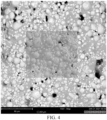
FIG. 4 is an electron microscope scanning image of part of a resistance heating trajectory of a heating assembly prepared by an implementation. -
FIG. 5 is an energy spectrum graph of a site of the resistance heating trajectory of the heating assembly prepared by an implementation. -
FIG. 6 is a schematic structural diagram of a vapor generation device provided by an embodiment of this application. -
FIG. 7 is a schematic structural diagram of an embodiment of a resistance heater inFIG. 6 . - It is to be understood that specific embodiments described herein are merely used to explain this application but are not intended to limit this application. For ease of understanding of this application, this application is illustrated below in more detail in conjunction with accompanying drawings and specific implementations. When an element is expressed as "being fixed to" another element, the element may be directly on the another element, or one or more intermediate elements may exist between the element and the another element. When one element is expressed as "being connected to" another element, the element may be directly connected to the another element, or one or more intermediate elements may exist between the element and the another element. Terms "upper", "lower", "left", "right", "inner", "outer", and similar expressions used in this description are merely used for illustrative purpose.
- Unless otherwise defined, meanings of all technical and scientific terms used in this description are the same as that usually understood by a person skilled in the art to which this application belongs. The terms used in this description of this application are merely intended to describe the objectives of the specific implementations and are not intended to limit this application. A term "and/or" used in this description includes any or all combinations of one or more related listed items.
- For ease of understanding of this application, this application is illustrated below in more detail in conjunction with accompanying drawings and specific implementations.
- Provided in this application is an aerosol generation device. Reference can be made to
FIG. 1 , the aerosol generation device includes avaporizer 100 storing a liquid substrate and vaporizing it to generate an aerosol, and apower supply assembly 200 supplying power to thevaporizer 100. - In an optional implementation, as shown in
FIG. 1 , thepower supply assembly 200 includes areceiving cavity 270 provided at an end in a length direction and used for receiving and accommodating at least part of thevaporizer 100. When the at least part of thevaporizer 100 is received and accommodated in thepower supply assembly 200, thepower supply assembly 200 is electrically connected with thevaporizer 100 to supply power to thevaporizer 100. In addition, thevaporizer 100 can be removed from the receivingcavity 270 for easy replacement and independent storage. - In
FIG. 1 , thevaporizer 100 includes:
aliquid storage cavity 12 used for storing a liquid substrate, and aheating assembly 30 sucking the liquid substrate and heating and vaporizing the liquid substrate to generate an aerosol. - Further specifically,
FIG. 2 shows a schematic structural diagram of an embodiment of thevaporizer 100 inFIG. 1 , and thevaporizer 100 includes: - a
main housing 10; - a suction nozzle A, formed at an upper end of the
main housing 10 and used for allowing a user to inhale the aerosol; - a
smoke output pipe 11, extending in a longitudinal direction of themain housing 10 and used for outputting the aerosol towards the suction nozzle A; - a
liquid storage cavity 12, defined by thesmoke output pipe 11 and an inner wall of themain housing 10 and used for storing the liquid substrate; - a
heating assembly 30, an upper side of theheating assembly 30 being in fluid communication with theliquid storage cavity 12 in a longitudinal direction of thevaporizer 100, wherein as shown in arrow R1 inFIG. 2 , the liquid substrate in theliquid storage cavity 12 flows towards theheating assembly 30 to be sucked; and theheating assembly 30 is provided with avaporization face 310 facing away from theliquid storage cavity 12, and thevaporization face 310 is used for heating the liquid substrate and releasing the generated aerosol; - a
vaporization chamber 22, defined by thevaporization face 310 and used for accommodating the released aerosol, wherein thevaporization chamber 22 is in airflow communication with thesmoke output pipe 11 to output the aerosol to thesmoke output pipe 11; and - an
electrode column 21, used for supplying power to theheating assembly 30. - Further referring to
FIG. 3 , the specific structure of theheating assembly 30 includes: - a
porous body 31, wherein in some implementations, theporous body 31 can be made of a rigid capillary structure such as porous ceramic, porous glass ceramic and porous glass; and in an implementation, a flat surface of theporous body 31 facing away from theliquid storage cavity 12 is configured as thevaporization face 310; and - a
resistance heating trajectory 32, wherein in some implementations, theresistance heating trajectory 32 is formed on thevaporization face 310 in such a way that a conductive raw material powder is mixed with a printing auxiliary to form a resistor paste, and then the resistor paste is printed and then sintered, so that all or most of the surface of theresistance heating trajectory 32 is tightly coupled with the vaporization face 320. - In some other variant implementations, the
porous body 31 can further have a flat plate shape, a concave shape with an upper surface facing theliquid storage cavity 12 provided with a cavity, an arched shape with one side of theliquid storage cavity 12 provided with an arched structure, etc. - In other preferred implementations, the
resistance heating trajectory 32 is a patterned trajectory. - In other preferred implementations, the
resistance heating trajectory 32 is formed in a stamped or printed manner. - In other preferred implementations, the
resistance heating trajectory 32 is in a flat shape. - In other preferred implementations, the
resistance heating trajectory 32 is a trajectory extending in a manner of meandering, detouring, etc. - In other preferred implementations, the
resistance heating trajectory 32 has a thickness of 60 to 100 µm. - After assembly, the
electrode column 21 abuts against two ends of theresistance heating trajectory 32 to form a conductive connection to supply power to theresistance heating trajectory 32. - Further provided in another embodiment of this application is a resistor paste for preparing the above
resistance heating trajectory 32, including: - a functional phase: an iron-silicon alloy powder;
- a glass phase: including at least one of oxides such as SiO2, Al2O3, MgO, CaO and B2O3; and
- a liquid organic auxiliary: used for assisting printing/stamping and sintering of the above functional phase and glass phase, wherein in an implementation, the liquid organic auxiliary includes at least an organic solvent, and can further enhance mixing of a thickener, a leveling agent, a surfactant, a dispersant, a thixotropic agent, etc., to improve and assist performance of the paste.
- For example, as for the liquid organic auxiliary, in an implementation:
- the organic solvent, the thickener and the leveling agent make the mixed paste have appropriate fluidity and plasticity; usually, in an implementation, the organic solvent includes at least one of ether lipids such as ether alcohols such as propylene glycol monomethyl ether, lactate lipids, and methyl cellosolve acetate; the thickener and the leveling agent can adjust stability of the mixed paste, and usually dibutyl phthalate, dioctyl phthalate and the like are adopted as the thickener;
- the dispersant makes the above functional phase and glass phase evenly dispersed in the paste; usually, polyethylene wax, paraffin and the like are adopted as the dispersant;
- the surfactant is used for improving surface performance of the paste to eliminate bubbles and the like coming out of mixing and stirring; usually, polysiloxane, dimethyl silicone oil and the like are adopted as the surfactant; and
- the thixotropic agent improves anti-sagging performance of the paste, and usually hydrogenated castor oil, polyvinyl alcohol and the like can be adopted as the thixotropic agent.
- In a preferred implementation, the resistor paste includes the following components in percentage by mass: 70% to 90% of the iron-silicon alloy powder, 4% to 14% of the glass phase, and 5% to 20% of the liquid organic auxiliary.
- In a preferred implementation, the iron-silicon alloy powder and/or a powder of the glass phase added in the resistor paste as a particle size of between 0.1 and 200 µm, which is advantageous to uniform dispersion of the powders. In a preferred implementation, the particle size within the above range can be obtained by water quenching and ball milling of raw materials.
- In a more preferred implementation, the resistor paste can further include: in percentage by mass, less than 1% of a pore-forming agent. In an implementation, the pore-forming agent can adopt cellulose, wood fibers, short carbon fibers, etc. In a sintering process, the pore-forming agent is burned or decomposed into a gas to escape, thus forming pores.
- Further provided in this application is a method for preparing a
heating assembly 30 from the above resistor paste, including: - S10, obtaining a
porous body 31; - S20, forming a precursor of a
resistance heating trajectory 32 on a surface of avaporization face 310 of theporous body 31 by screen-printing or spraying the resistor paste; and - S30, sintering or heat-treating the
porous body 31 with the precursor of theresistance heating trajectory 32 to solidify the precursor of theresistance heating trajectory 32 into theresistance heating trajectory 32. - In the process of sintering or heat treatment in step S30, a liquid organic auxiliary and a pore-forming agent will decompose and evaporate, and do not remain in the
resistance heating trajectory 32. Usually, sintering or heat treatment is conducted in a sintering furnace device and the like at a temperature of from 900 to 1200°C. The sintering time is controlled between 20 to 90 min. Finally, a mass percentage of an iron-silicon alloy phase in theresistance heating trajectory 32 after sintering ranges from 80% to 95%. - Certainly, in a preferred implementation, in order to prevent the functional phase of an iron-silicon alloy from being oxidized in the sintering process, the sintering process is conducted in a reducing atmosphere.
- In the
resistance heating trajectory 32 formed after sintering, there are only a cured glass phase and the functional phase of the iron-silicon alloy, and during power supply, a liquid substrate sucked in theporous body 31 can be heated to generate an aerosol. - In a more preferred implementation, by adjusting the components of the functional phase, such as correspondingly and properly replenishing and increasing metal platinum/palladium with a high resistance temperature coefficient, and correspondingly adjusting the content of silicon in the iron-silicon alloy, such as controlling the mass percentage of silicon to 3% to 15%, a resistance temperature coefficient of the finally prepared
resistance heating trajectory 32 is adjustable within an expected range, such as 900 to 3000 ppm/°C. Thus, during use, the temperature of theresistance heating trajectory 32 can be determined by detecting the resistance temperature coefficient of theresistance heating trajectory 32. - Further, in order to facilitate the demonstration of performance consistence and stability of the heating assembly prepared through the above method, the prepared heating assembly is illustrated below with examples and results through specific embodiments.
-
- S10, obtaining a
porous body 31 shown inFIG. 2 andFIG. 3 with an average porosity of 60%; - S20, preparing a resistor paste, wherein the resistor paste includes 75 wt% of an iron-silicon alloy powder, 10 wt% of a glass phase, 1 wt% of a pore-forming agent, and 14 wt% of a liquid organic auxiliary; wherein
the iron-silicon alloy powder includes 6.5 wt% of silicon, denoted as FeSi6.5; the glass phase includes 63 wt% of silicon dioxide, 15 wt% of calcium oxide, and 22 wt% of aluminum oxide; the liquid organic auxiliary includes 35 wt% of terpineol, 15 wt% of butyl carbitol, 6 wt% of 1,4-butyrolactone, 24 wt% of tributyl citrate, 15 wt% of ethyl cellulose, and 5 wt% of hydrogenated castor oil; and particle sizes of the iron-silicon alloy powder and the glass phase are controlled to about 1 to 5 µm through sieving; - S30, subjecting the resistor paste in step S20 to working procedures of stirring, triple roller grinding, filtering and debubbling, followed by screen printing on a
vaporization face 310 of theporous body 31 to form a precursor of aresistance heating trajectory 32 in a shape inFIG. 3 ; and the printing thickness is 60 µm, and the printed circuit width of the trajectory is 0.35 mm; and - S40, sintering the
porous body 31 with the precursor of theresistance heating trajectory 32 after printing in step S30 in a sintering furnace with a reducing atmosphere; wherein sintering is conducted at a temperature of 1050°C for 30 min; and after sintering is completed, the heating assembly prepared inEmbodiment 1 is taken out. -
- S10, obtaining a
porous body 31 shown inFIG. 2 andFIG. 3 with an average porosity of 60%; - S20, preparing a resistor paste, wherein the resistor paste includes 78 wt% of an iron-silicon alloy powder, 5 wt% of a glass phase, 1 wt% of a pore-forming agent, and 16 wt% of a liquid organic auxiliary; wherein
the iron-silicon alloy powder includes 10 wt% of silicon, denoted as FeSi10; the glass phase includes 63 wt% of silicon dioxide, 15 wt% of calcium oxide, and 22 wt% of aluminum oxide; the liquid organic auxiliary includes 35 wt% of terpineol, 15 wt% of butyl carbitol, 6 wt% of 1,4-butyrolactone, 24 wt% of tributyl citrate, 15 wt% of ethyl cellulose, and 5 wt% of hydrogenated castor oil; and particle sizes of the iron-silicon alloy powder and the glass phase are controlled to about 1 to 5 µm through sieving; - S30, subjecting the resistor paste in step S20 to working procedures of stirring, triple roller grinding, filtering and debubbling, followed by screen printing on a
vaporization face 310 of theporous body 31 to form a precursor of aresistance heating trajectory 32 in a shape inFIG. 3 ; and the printing thickness is 60 µm, and the printed circuit width of the trajectory is 0.35 mm; and - S40, sintering the
porous body 31 with the precursor of theresistance heating trajectory 32 after printing in step S30 in a sintering furnace with a reducing atmosphere; wherein sintering is conducted at a temperature of 1050°C for 30 min; and after sintering is completed, the heating assembly prepared inEmbodiment 1 is taken out. -
Embodiment 3 adopts the same method steps asEmbodiment 1. In preparation of a resistor paste, 71 wt% of a functional phase of an iron-silicon alloy powder and 14 wt% of a glass phase are used for preparing a heating assembly ofEmbodiment 3. - Embodiment 4 adopts the same method steps as
Embodiment 2. In preparation of a resistor paste, the content of silicon in the functional phase of the iron-silicon alloy powder is adjusted to 12 wt% to prepare a heating assembly ofEmbodiment 3. -
Embodiment 5 adopts the same method steps asEmbodiment 1. In preparation of a resistor paste, 88 wt% of an iron-silicon alloy powder, 5 wt% of a glass phase, and 7 wt% of a liquid organic auxiliary are used; wherein, the content of silicon in the functional phase of the iron-silicon alloy powder is 3.5 wt%; and a heating assembly ofEmbodiment 5 is prepared according to the above steps. - Various verifications are conducted on the above prepared heating assembly, and specifically include:
S50, detecting resistance temperature coefficients, wherein the resistance temperature coefficients of theresistance heating trajectories 32 in the heating assemblies prepared in the above embodiments are measured, and results are shown in the following table:Functional phase Resistance temperature coefficient (ppm/°C) Embodiment 1Iron-silicon alloy FeSi6.5 917 Embodiment 2Iron-silicon alloy FeSi10 1245 Embodiment 3Iron-silicon alloy FeSi12 964 Embodiment 4 Iron-silicon alloy FeSi15 848 Embodiment 5Iron-silicon alloy FeSi3.5 2343 - S60, conducting electron microscope scanning on the
resistance heating trajectory 32 of the heating assembly sample prepared inEmbodiment 2 to obtain micromorphology of theresistance heating trajectory 32, as shown inFIG. 4 ; and meanwhile, conducting energy spectrum analysis on a central site inFIG. 4 to obtain an energy spectrum graph, as shown inFIG. 5 . - Further, proportions of element components obtained by energy spectrum analysis in
FIG. 5 are shown in the following table:Element Percentage by atom number/% Percentage by weight % Fe 38.65 61.54 0 32.19 14.68 Si 27.94 22.37 Ca 1.23 1.40 - Among the proportions of the elements of energy spectrum analysis reflected in
FIG. 5 and the above table, also mainly iron and silicon; and among the percentages of the above elements, the glass phase provides part of silicon oxide, thus the content of the silicon element at the analysis site is greater than the content of silicon described in the functional phase, but the functions are still provided by the iron-silicon alloy. In addition, it can be seen from a color distinction inFIG. 4 that the functional element components in a measured area are all iron and silicon. - Further provided in yet another embodiment of this application is a vapor generation device, with a structure shown in
FIG. 4 , including: - a chamber, used for receiving a solid aerosol generation product A;
- a
resistance heater 30a, at least partially extending in the chamber to heat the aerosol generation product A to generate an aerosol for inhaling; - a
battery cell 10a, used for supplying power; and - a
controller 20a, guiding a current between thebattery cell 10a and theresistance heater 30a. - Referring to
FIG. 5 for a structure of theresistance heater 30a, including: - an
electrical insulation substrate 31a, wherein theelectrical insulation substrate 31a can be made of materials, such as ceramic, rigid plastic, a surface insulation metal and polyimide; preferably, theelectrical insulation substrate 31a is in a shape of a rigid pin or a thin blade, which can be inserted into the aerosol generation product A during use to heat the aerosol generation product A; or in other variant implementations, theelectrical insulation substrate 31a can further in a tubular shape surrounding the chamber/the aerosol generation product A; and - a
resistance heating trajectory 32a, coupled to theelectrical insulation substrate 31a in a printed or deposited manner; wherein theresistance heating trajectory 32a is prepared from the above resistor paste with the iron-silicon alloy as the functional phase. During use, theresistance heating trajectory 32a does not contain heavy metals such as nickel/chromium/tungsten, and meanwhile can have a resistance temperature coefficient of from 900 to 3000 ppm/°C, so that the temperature of theresistance heater 30a can be measured through. - Preferred embodiments of this application are given in the description of this application and the accompanying drawings thereof. However, this application may be implemented in various different forms, and is not limited to the embodiments described in this description. These embodiments are not intended to be an additional limitation on the content of this application, and are described for the purpose of providing a more thorough and comprehensive understanding of the content disclosed in this application. Moreover, the foregoing technical features are further combined with each other to form various embodiments not listed above, and all such embodiments shall be construed as falling within the scope of the description of this application. Further, a person of ordinary skill in the art may make improvements or modifications according to the foregoing illustrations, and all the improvements and modifications shall fall within the protection scope of the appended claims of this application.
Claims (13)
- A vaporizer, used for vaporizing a liquid substrate to generate an aerosol for inhaling, and comprising:a liquid storage cavity, used for storing the liquid substrate;a porous body, being in fluid communication with the liquid storage cavity to suck the liquid substrate, the porous body comprising a vaporization face; anda resistance heating trajectory, formed on the vaporization face and used for heating at least part of the liquid substrate in the porous body to generate the aerosol, the resistance heating trajectory comprising an iron-silicon alloy.
- The vaporizer according to claim 1, wherein the resistance heating trajectory has a resistance temperature coefficient of from 900 to 3000 ppm/°C.
- The vaporizer according to claim 1 or 2, wherein a mass percentage of silicon in the iron-silicon alloy of the resistance heating trajectory ranges from 3% to 15%.
- The vaporizer according to claim 1 or 2, wherein the resistance heating trajectory does not contain any one of nickel, chromium or tungsten.
- The vaporizer according to claim 1 or 2, wherein a mass percentage of the iron-silicon alloy in the resistance heating trajectory ranges from 80% to 95%.
- The vaporizer according to claim 5, wherein the resistance heating trajectory further comprises a glass phase component, the glass phase component comprising at least one of SiO2, Al2O3, MgO, CaO or B2O3.
- A resistor paste, comprising:an iron-silicon alloy;a glass phase component; anda liquid organic auxiliary, the liquid organic auxiliary comprising at least an organic solvent.
- The resistor paste according to claim 7, comprising: 70 to 90 wt% of the iron-silicon alloy, 4 to 14 wt% of the glass phase, and 5 to 20 wt% of the liquid organic auxiliary.
- The resistor paste according to claim 7 or 8, wherein the glass phase component comprises at least one of SiO2, Al2O3, MgO, CaO or B2O3.
- A heating assembly, comprising:
an electrical insulation base body, and a resistance heating trajectory formed on the electrical insulation base body, the resistance heating trajectory comprising an iron-silicon alloy. - The heating assembly according to claim 10, wherein the electrical insulation base body comprises a porous body.
- An aerosol generation device, comprising a vaporizer vaporizing a liquid substrate to generate an aerosol, and a power supply assembly supplying power to the vaporizer, wherein the vaporizer comprises the vaporizer according to any one of claims 1-6.
- An aerosol generation device, comprising:a chamber, configured to receive an aerosol generation product; anda resistance heater, used for heating the aerosol generation product, the resistance heater comprising an electrical insulation substrate, and a resistance heating trajectory formed on the electrical insulation substrate, and the resistance heating trajectory comprising an iron-silicon alloy.
Applications Claiming Priority (2)
| Application Number | Priority Date | Filing Date | Title |
|---|---|---|---|
| CN202110175680.0A CN114903207A (en) | 2021-02-06 | 2021-02-06 | Atomizer, resistance paste, heating assembly and aerosol generating device |
| PCT/CN2022/073540 WO2022166660A1 (en) | 2021-02-06 | 2022-01-24 | Atomizer, resistive slurry, heating assembly, and aerosol generation device |
Publications (2)
| Publication Number | Publication Date |
|---|---|
| EP4289300A1 true EP4289300A1 (en) | 2023-12-13 |
| EP4289300A4 EP4289300A4 (en) | 2024-08-14 |
Family
ID=82740858
Family Applications (1)
| Application Number | Title | Priority Date | Filing Date |
|---|---|---|---|
| EP22748939.0A Pending EP4289300A4 (en) | 2021-02-06 | 2022-01-24 | ATOMIZER, RESISTIVE SLURRY, HEATING ARRANGEMENT AND AEROSOL GENERATING DEVICE |
Country Status (3)
| Country | Link |
|---|---|
| EP (1) | EP4289300A4 (en) |
| CN (1) | CN114903207A (en) |
| WO (1) | WO2022166660A1 (en) |
Family Cites Families (16)
| Publication number | Priority date | Publication date | Assignee | Title |
|---|---|---|---|---|
| US2767288A (en) * | 1954-04-26 | 1956-10-16 | Gen Electric | Electric heating unit |
| JP2627506B2 (en) * | 1987-06-09 | 1997-07-09 | 東海高熱工業株式会社 | Far infrared heater |
| JPH09180863A (en) * | 1995-12-26 | 1997-07-11 | Tokai Konetsu Kogyo Co Ltd | Ceramic heater member for heat roller and manufacture thereof |
| EP2316286A1 (en) * | 2009-10-29 | 2011-05-04 | Philip Morris Products S.A. | An electrically heated smoking system with improved heater |
| CN104036906B (en) * | 2014-06-05 | 2016-06-08 | 浙江大学 | The curtain coating temperature isostatic pressed composite molding preparation method of a kind of soft magnetic metal matrix material |
| CN104465020B (en) * | 2014-12-25 | 2017-05-03 | 深圳市固电电子有限公司 | Cascading inductor based on metal magnetic slurry and preparation method thereof |
| KR20190017907A (en) * | 2016-06-27 | 2019-02-20 | 니뽄 다바코 산교 가부시키가이샤 | A flavor aspirator having a cartridge for a flavor aspirator and a cartridge for the flavor aspirator |
| CN209498585U (en) * | 2018-12-28 | 2019-10-18 | 深圳市合元科技有限公司 | Cartridges and Electronic Cigarettes |
| CN109619697A (en) * | 2019-01-28 | 2019-04-16 | 深圳市卓力能电子有限公司 | Atomization core and preparation method thereof, aerosol generating device |
| US20220132930A1 (en) * | 2019-03-07 | 2022-05-05 | O-Net Automation Technology (Shenzhen) Limited | Electronic Cigarette Atomization Assembly and Manufacturing Method Therefor |
| CN210520094U (en) * | 2019-06-24 | 2020-05-15 | 深圳哈卡科技有限公司 | Atomizer and electronic cigarette |
| CN110279162B (en) * | 2019-07-30 | 2024-11-08 | 深圳雾芯科技有限公司 | Atomization device and method thereof |
| CN112790427B (en) * | 2019-11-13 | 2024-06-14 | 深圳市合元科技有限公司 | Atomizer assembly for electronic cigarette, preparation method of atomizer assembly and electronic cigarette |
| CN212590295U (en) * | 2020-08-20 | 2021-02-26 | 深圳市合元科技有限公司 | Electronic cigarette, electronic cigarette atomizer and atomization assembly |
| CN114246370B (en) * | 2020-09-23 | 2025-08-08 | 深圳麦克韦尔科技有限公司 | Heating components and aerosol forming devices |
| CN215303022U (en) * | 2021-01-27 | 2021-12-28 | 深圳市华诚达精密工业有限公司 | Three-dimensional atomization assembly and atomizer thereof |
-
2021
- 2021-02-06 CN CN202110175680.0A patent/CN114903207A/en active Pending
-
2022
- 2022-01-24 EP EP22748939.0A patent/EP4289300A4/en active Pending
- 2022-01-24 WO PCT/CN2022/073540 patent/WO2022166660A1/en not_active Ceased
Also Published As
| Publication number | Publication date |
|---|---|
| CN114903207A (en) | 2022-08-16 |
| EP4289300A4 (en) | 2024-08-14 |
| WO2022166660A1 (en) | 2022-08-11 |
Similar Documents
| Publication | Publication Date | Title |
|---|---|---|
| EP3881696B1 (en) | Porous heating body and atomizer comprising same | |
| US20250302105A1 (en) | Electronic atomization apparatus, and atomizer and heating body of electronic atomization apparatus | |
| CN210203364U (en) | Electronic cigarette atomizer and electronic cigarette | |
| CN112790427B (en) | Atomizer assembly for electronic cigarette, preparation method of atomizer assembly and electronic cigarette | |
| CN109832673A (en) | Electronic smoke atomizer, electronic cigarette, atomizing component and preparation method thereof | |
| CN212590295U (en) | Electronic cigarette, electronic cigarette atomizer and atomization assembly | |
| CN115159991B (en) | Porous ceramic heating structure and preparation method thereof | |
| US12610984B2 (en) | E-cigarette, e-cigarette vaporizer, and vaporization assembly with curved resistance heating trajectory | |
| EP4324348A1 (en) | Aerosol generation apparatus and infrared heater | |
| JP2019518423A (en) | Needle type heater, method of manufacturing the same, and electrically heated cigarette provided with needle type heater | |
| CN110022622B (en) | Alumina honeycomb ceramic heating body and preparation method thereof | |
| EP4218450A1 (en) | Aerosol generating device and infrared heater | |
| EP4316283A1 (en) | Aerosol generating apparatus and heater | |
| CN111770593A (en) | Heating element, preparation method thereof and heating device | |
| CN111182662A (en) | Graphene electric heating piece, and manufacturing process and application thereof | |
| CN115947619B (en) | Humidity-sensitive heating slurry, preparation method thereof and atomization core | |
| US20240138478A1 (en) | Electronic cigarette atomization core, preparation method for electronic cigarette atomization core, electronic cigarette atomization assembly, and electronic cigarette | |
| CN114947225B (en) | Ceramic heating sheet for heating nonflammable electronic cigarette and preparation method thereof | |
| CN114176263A (en) | Heating assembly, preparation method of heating assembly and electronic atomization device | |
| CN217547272U (en) | Heating element and electronic atomization device | |
| EP4218440A1 (en) | Aerosol generating device and infrared heater | |
| CN116058550A (en) | A kind of atomizing core and preparation method thereof | |
| WO2022166660A1 (en) | Atomizer, resistive slurry, heating assembly, and aerosol generation device | |
| CN116172265A (en) | Atomization core, preparation method thereof, and electronic cigarette atomizer | |
| US20250064128A1 (en) | Resistive heater for use in aerosol generation apparatus, and aerosol generation apparatus |
Legal Events
| Date | Code | Title | Description |
|---|---|---|---|
| STAA | Information on the status of an ep patent application or granted ep patent |
Free format text: STATUS: THE INTERNATIONAL PUBLICATION HAS BEEN MADE |
|
| PUAI | Public reference made under article 153(3) epc to a published international application that has entered the european phase |
Free format text: ORIGINAL CODE: 0009012 |
|
| STAA | Information on the status of an ep patent application or granted ep patent |
Free format text: STATUS: REQUEST FOR EXAMINATION WAS MADE |
|
| 17P | Request for examination filed |
Effective date: 20230818 |
|
| AK | Designated contracting states |
Kind code of ref document: A1 Designated state(s): AL AT BE BG CH CY CZ DE DK EE ES FI FR GB GR HR HU IE IS IT LI LT LU LV MC MK MT NL NO PL PT RO RS SE SI SK SM TR |
|
| DAV | Request for validation of the european patent (deleted) | ||
| DAX | Request for extension of the european patent (deleted) | ||
| REG | Reference to a national code |
Ref country code: DE Ref legal event code: R079 Free format text: PREVIOUS MAIN CLASS: A24F0047000000 Ipc: A24F0040460000 |
|
| STAA | Information on the status of an ep patent application or granted ep patent |
Free format text: STATUS: EXAMINATION IS IN PROGRESS |
|
| A4 | Supplementary search report drawn up and despatched |
Effective date: 20240712 |
|
| RIC1 | Information provided on ipc code assigned before grant |
Ipc: A24F 40/10 20200101ALN20240708BHEP Ipc: A24F 40/42 20200101ALN20240708BHEP Ipc: A24F 40/70 20200101ALN20240708BHEP Ipc: H05B 3/26 20060101ALI20240708BHEP Ipc: H05B 3/14 20060101ALI20240708BHEP Ipc: H05B 3/04 20060101ALI20240708BHEP Ipc: A24F 40/44 20200101ALI20240708BHEP Ipc: A24F 40/46 20200101AFI20240708BHEP |
|
| 17Q | First examination report despatched |
Effective date: 20240724 |