EP4289292A1 - A cutting device and a method for cutting tobacco industry material - Google Patents
A cutting device and a method for cutting tobacco industry material Download PDFInfo
- Publication number
- EP4289292A1 EP4289292A1 EP23175954.9A EP23175954A EP4289292A1 EP 4289292 A1 EP4289292 A1 EP 4289292A1 EP 23175954 A EP23175954 A EP 23175954A EP 4289292 A1 EP4289292 A1 EP 4289292A1
- Authority
- EP
- European Patent Office
- Prior art keywords
- opening
- cutting
- channel
- shield
- cutting device
- Prior art date
- Legal status (The legal status is an assumption and is not a legal conclusion. Google has not performed a legal analysis and makes no representation as to the accuracy of the status listed.)
- Pending
Links
Images




Classifications
-
- A—HUMAN NECESSITIES
- A24—TOBACCO; CIGARS; CIGARETTES; SIMULATED SMOKING DEVICES; SMOKERS' REQUISITES
- A24B—MANUFACTURE OR PREPARATION OF TOBACCO FOR SMOKING OR CHEWING; TOBACCO; SNUFF
- A24B7/00—Cutting tobacco
- A24B7/04—Cutting tobacco by machines with revolving knives
-
- A—HUMAN NECESSITIES
- A24—TOBACCO; CIGARS; CIGARETTES; SIMULATED SMOKING DEVICES; SMOKERS' REQUISITES
- A24B—MANUFACTURE OR PREPARATION OF TOBACCO FOR SMOKING OR CHEWING; TOBACCO; SNUFF
- A24B7/00—Cutting tobacco
- A24B7/04—Cutting tobacco by machines with revolving knives
- A24B7/08—Cutting tobacco by machines with revolving knives with several knives which act one after the other
- A24B7/12—Cutting tobacco by machines with revolving knives with several knives which act one after the other with cutter axes transverse to the feeding direction
-
- A—HUMAN NECESSITIES
- A24—TOBACCO; CIGARS; CIGARETTES; SIMULATED SMOKING DEVICES; SMOKERS' REQUISITES
- A24B—MANUFACTURE OR PREPARATION OF TOBACCO FOR SMOKING OR CHEWING; TOBACCO; SNUFF
- A24B7/00—Cutting tobacco
- A24B7/14—Feeding or control devices for tobacco-cutting apparatus
-
- B—PERFORMING OPERATIONS; TRANSPORTING
- B26—HAND CUTTING TOOLS; CUTTING; SEVERING
- B26D—CUTTING; DETAILS COMMON TO MACHINES FOR PERFORATING, PUNCHING, CUTTING-OUT, STAMPING-OUT OR SEVERING
- B26D1/00—Cutting through work characterised by the nature or movement of the cutting member or particular materials not otherwise provided for; Apparatus or machines therefor; Cutting members therefor
- B26D1/01—Cutting through work characterised by the nature or movement of the cutting member or particular materials not otherwise provided for; Apparatus or machines therefor; Cutting members therefor involving a cutting member which does not travel with the work
- B26D1/12—Cutting through work characterised by the nature or movement of the cutting member or particular materials not otherwise provided for; Apparatus or machines therefor; Cutting members therefor involving a cutting member which does not travel with the work having a cutting member moving about an axis
- B26D1/25—Cutting through work characterised by the nature or movement of the cutting member or particular materials not otherwise provided for; Apparatus or machines therefor; Cutting members therefor involving a cutting member which does not travel with the work having a cutting member moving about an axis with a non-circular cutting member
- B26D1/34—Cutting through work characterised by the nature or movement of the cutting member or particular materials not otherwise provided for; Apparatus or machines therefor; Cutting members therefor involving a cutting member which does not travel with the work having a cutting member moving about an axis with a non-circular cutting member moving about an axis parallel to the line of cut
- B26D1/38—Cutting through work characterised by the nature or movement of the cutting member or particular materials not otherwise provided for; Apparatus or machines therefor; Cutting members therefor involving a cutting member which does not travel with the work having a cutting member moving about an axis with a non-circular cutting member moving about an axis parallel to the line of cut and coacting with a fixed blade or other fixed member
- B26D1/385—Cutting through work characterised by the nature or movement of the cutting member or particular materials not otherwise provided for; Apparatus or machines therefor; Cutting members therefor involving a cutting member which does not travel with the work having a cutting member moving about an axis with a non-circular cutting member moving about an axis parallel to the line of cut and coacting with a fixed blade or other fixed member for thin material, e.g. for sheets, strips or the like
-
- A—HUMAN NECESSITIES
- A24—TOBACCO; CIGARS; CIGARETTES; SIMULATED SMOKING DEVICES; SMOKERS' REQUISITES
- A24D—CIGARS; CIGARETTES; TOBACCO SMOKE FILTERS; MOUTHPIECES OF CIGARS OR CIGARETTES; MANUFACTURE OF TOBACCO SMOKE FILTERS OR MOUTHPIECES
- A24D3/00—Tobacco smoke filters, e.g. filter tips or filtering inserts; Filters specially adapted for simulated smoking devices; Mouthpieces of cigars or cigarettes
- A24D3/02—Manufacture of tobacco smoke filters
- A24D3/0204—Preliminary operations before the filter rod forming process, e.g. crimping, blooming
- A24D3/0208—Cutting filter materials
Definitions
- the present invention relates to a cutting device and a method for cutting tobacco industry material.
- cutters i.e. devices for cutting material such as tobacco leaves, tobacco film, cloves.
- materials comprising plant or plastic fibers impregnated with aromatic substances are increasingly used. Such materials may be produced in the form of sheets or strips. Due to the required efficiency and the difficulty of cutting a single sheet or strip of such material, such material is cut in several layers, that is, in at least two layers.
- the chamber is formed by the inner surface of the shield and the cavity formed by the side surface of the cutting head and by two adjacent knives protruding above the side surface of the cutting head drum.
- the chamber is pressurized slightly higher than the surrounding pressure of the slicer, even though a certain gap is left between the edges of the knives and the inner surface of the shield.
- the knife approaches the mouthpiece of the cutter, it causes the opening of such a chamber and a dynamic lowering of the pressure in the chamber, generally in the space adjacent to the peripheral surface of the drum, which causes vibrations of the material being cut and, consequently, a reduction in the quality of the cut.
- the vibrations of the material being cut is reduced when the air exchange occurs in the cavity before the knife reaches the mouthpiece at a point where the air exchange does not affect the material being cut.
- the inventors found that increasing the pressure difference between the cavity (i.e. the chamber when the cutting head is rotated) and the surrounding space causes the material to be pressed against the lower edge of the mouthpiece, i.e. the temporary immobilization of the material, which lasts long enough, i.e. until the moment of cutting, thus also improving the quality of the cut.
- the object of the invention is a cutting device for cutting tobacco industry material, the device comprising: a body, a feeder for feeding the material, a mouthpiece located at the outlet of the feeder, a cutting head comprising a drum with knives located on a peripheral surface of the drum, and a shield for the cutting head, wherein an axis of rotation of the cutting head is located transverse to the direction of feeding of the material on the feeder.
- the shield comprises an opening for exchanging air between surrounding space of the cutting device and a cavity limited by the peripheral surface of the drum and two adjacent knives.
- the shield may be provided with a valve.
- the valve may comprise an aperture in the form of a cylindrical cutout, wherein the aperture and the opening in the shield form together an opening of a variable width.
- the device may further comprise a channel attached to the opening.
- the channel may be a vacuum channel.
- the channel may be a blow channel.
- the device may further comprise a channel attached to the opening, configured to supply air flow.
- the device may further comprise a channel with a valve attached to the opening, configured to supply negative pressure.
- the cutting device may be adapted to cut the material in the form of sheets or strips arranged in at least two layers.
- the invention also relates to a method for cutting tobacco industry material in a cutting device, the method comprising the steps of: feeding the material; cutting the material by means of a cutting head comprising a drum with knives located on a peripheral surface of the drum, wherein a shield having an opening is located at a side surface of the drum.
- the method further comprises a step of exchanging air between the surrounding space of the cutting device and a cavity limited by the peripheral surface of the drum and two adjacent knives, during rotation of the cutting head.
- the method may comprise a step of exchanging air and reducing pressure through the opening in the shield of the cutting head.
- the method may comprise a step of exchanging air and reducing pressure through a valve comprising an aperture located at the opening in the shield of the cutting head.
- the method may comprise a step of exchanging air and reducing pressure by supplying negative pressure to the opening in the shield through a channel attached to the opening.
- the method may comprise a step of exchanging air and reducing pressure by supplying negative pressure to the opening through a channel attached to the opening, wherein the degree of pressure reduction is adjusted by a valve located in the channel.
- the method may comprise a step of exchanging air and increasing pressure by means of a stream of air directed through the channel to the opening in the shield.
- the method may comprise a step of exchanging air and increasing the pressure by providing positive pressure to the opening through a channel attached to the opening.
- the material may have the form of sheets or strips arranged in at least two layers.
- Fig. 1 shows a cutting device 1 for cutting material 2 of the tobacco industry.
- the cutting device 1 is adapted to cut the material 2, which may be in the form of fibers, strips or sheets of material of organic or inorganic origin.
- the tobacco industry material may be a material of the group comprising tobacco, reconstituted tobacco, processed tobacco, paper, cellulose, fibrous material, corn foil, plastic, cotton or any other material suitable for use in the tobacco industry in the manufacture of articles for smoking, heating or inhalation, for example, a material that may be impregnated with fragrances or substances comprising nicotine.
- the cutting device 1 shown in Fig. 1 comprises a supplying unit 3, a feeder 4 and a cutting head 5, wherein these units are located on a body 6, wherein the body may be one-element or multi-element.
- the supplying unit 3 feeds the material 2 for cutting, wherein the supplying unit 3 is in the form of a hopper 7.
- the supplying unit 3 may be in the form of a conveyor or an assembly having multiple conveyors.
- the feeder 4 is positioned substantially horizontally and feeds the material 2 in a direction T towards the cutting head 5.
- the feeder 4 comprises a bottom conveyor 8 and an upper conveyor 9, wherein the conveyors 8 and 9 are aligned convergently so that the fed material 2 is compressed during feeding.
- the feeder 4 is provided with a mouthpiece 10 through which the fed compressed material 2 passes.
- the mouthpiece 10 is located at the outlet 4A of the feeder 4 ( Fig. 2 ).
- the cutting head 5 is in the form of a drum 11 with a rotation axis k, wherein the rotation axis k is positioned horizontally and transverse to the feeding direction T, in the embodiment shown the rotation axis k is positioned perpendicular to the feeding direction T.
- a shield 14 which is shaped as a cylinder sector that is equidistant from the side surface 12 of the drum 11. A clearance is maintained between the knives 13 and the shield 14, the knives 13 are not in contact with the shield 14.
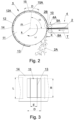
- An opening 15 is made in the shield 14, the opening 15 may be of any shape, in the embodiments shown, the opening 15 is rectangular, as shown in the expanded view of the shield 14 in Fig. 3 , where the lengths of the sides of the opening are indicated as D and R.
- the dimension D may be close to the distance between adjacent knives 13 on the cutting head 5.
- the dimension D is larger than the distance E between adjacent knives 13, the dimension R may be close to the length L of the knife 13, in the embodiment shown, the dimension R is smaller than the length of the knife 13.
- the shields substantially perpendicular to the axis of rotation k, which shield the front surfaces of the drum 11, are not shown.
- the movement of the material 2 being fed for cutting provides for the cutting off of individual pieces 2A of the material 2.
- Consecutive knives 13 cut off the pieces 2A, wherein the width of the pieces 2A depends on the feeding speed of the feeder 3, the distance E between the knives 13 and the rotational speed ⁇ of the cutting head 5.
- the end 2B of the material 2 is at a distance X from the compression point of the material between the rollers 8A and 9A.
- the material 2 is slidingly supported by the mouthpiece 10 and may vibrate. When a full shield is used, i.e. without openings, the tip of the material 2 sets in vibrations, especially when the thickness of the fed material 2 is small.
- the space adjacent to the peripheral surface 12 of the cutting head 5 is designated as 12A.
- the adjacent space 12A during rotation of the cutting head 5 in the area under the shield 14 is enclosed and constitutes a cavity 12A, which is movable and moves in a circular path under the stationary shield 14.
- the cavity 12A is limited by the side surface 12 of the drum 11 and the two adjacent knives 13, wherein a chamber is formed when the cavity 12A is shielded by the shield 14.
- a slight overpressure is created in the cavity 12A during the rotation of the drum, wherein the overpressure is reduced when the cavity 12A passes the shield 14 and the cavity 12A reaches the mouthpiece 10, which causes the material 2 to vibrate.
- the cutting device is particularly able to cut the material in the form of sheets or strips arranged in at least two layers.
- the shield 14 in the first of embodiment is provided with an opening 15, wherein the position of the opening 15 may be defined by referring to the center 15A of the opening 15, the line m connecting the axis of rotation k and the center 15A of the opening 15 defines the angular position of the center 15A.
- the center 15A of the opening 15 is located at an angle ⁇ with respect to the direction of feeding T of the material 2 on the feeder 4 with respect to the rotation axis k, wherein the direction T is oriented substantially horizontally.
- the angle ⁇ is in the range of 10° to 90°.
- the cutting device is provided with a valve 17 that comprises a movable aperture 16.
- the aperture 16 may change its position in direction W, i.e. rotate with respect to the axis k, wherein a mechanism for changing the position of the aperture 16 is not shown, wherein the aperture 16 has the form of a cylinder sector.
- the aperture 16 may have another form, for example, the form of a solid, one of the surfaces of the solid is concave being adjacent to the outer surface of the shield 14.
- the placement of the aperture 16 on the shield 14 creates an opening 18 of variable width d. Air exchange between the cavity 12A and the surrounding space will take place through the opening 18.
- the shield 16 By changing the position of the shield 16, it will be possible to obtain an opening 18 of a width that ensures effective air exchange, at which material vibrations will be minimized.
- the angular position of the opening 18 described by the angle ⁇ with respect to the direction of feeding T of the material 2 will be variable.
- the cutting device is provided with a channel 20, which is located above the opening 15, in other words, the channel 20 is attached to the opening 15.
- Air exchange between the cavity 12A and the surrounding space is carried out through the channel 20. Movement of the air along the channel 20 to the surrounding space in direction V is possible by the use of negative pressure (for example, by means of a single-stage or multi-stage vacuum generator), also in direction U to the cutting head by air blowing (for example, by means of a blower).
- a variant is possible, in which the channel 20 is attached to the opening 18 having the variable width d.
- the cutting device is provided with a channel 21 attached to the opening 15.
- the cutting off of the material 2 takes place after a shorter time from the air exchange in the cavity 12A.
- the angle ⁇ defining the angular position of the opening 15 is smaller than in the earlier embodiments.
- An air flow is supplied through the channel 21 by means of a blower (not shown), which provides air exchange in the space adjacent to the peripheral surface, i.e. in the cavities 12A, 12A'. Air movement and displacement of the cavity 12A provide air exchange and pressure change immediately before cutting, so that the material 2 does not vibrate. It is possible to reduce the angle ⁇ so that the air exchange occurs just before the ends 2B of material 2 are cut off.
- the movement of air in cavity 12A may cause a temporary drop in pressure on the side of knife 13 and a temporary increase in pressure on the side of the knife 13'.
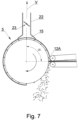
- the cutting device is provided with a channel 22 in which a valve 23 is located.
- the channel 22 is a vacuum channel and the valve 23 is in the form of a throttle, wherein a mechanism for turning the throttle is not shown.
- the use of the valve 23 makes it possible to control the speed of air extracted from the space adjacent to the side surface 12 of the cutting head 5.
- the cutting device is also provided with the channel 22 in which the valve 23 is located.
- the opening 15 in the shield 14 is wider than in the earlier examples, moreover, the extreme points 25, 26 of the foot of the channel 22 are located at a greater distance from each other.
- the position of the extreme points 25, 26 is described by the angles ⁇ and Y, respectively.
- the angle ⁇ may be equal from 180° to 270°
- the angle Y may be equal from 90° to 180°. In the embodiment shown, the angle ⁇ is 180°. It is possible to locate the opening 15, for which the angle ⁇ is up to 270° both in this embodiment and in the previously described embodiments of the cutting device.
Landscapes
- Life Sciences & Earth Sciences (AREA)
- Forests & Forestry (AREA)
- Engineering & Computer Science (AREA)
- Mechanical Engineering (AREA)
- Manufacturing Of Cigar And Cigarette Tobacco (AREA)
Abstract
Description
- The present invention relates to a cutting device and a method for cutting tobacco industry material.
- In the tobacco industry there are known cutters, i.e. devices for cutting material such as tobacco leaves, tobacco film, cloves. Currently, materials comprising plant or plastic fibers impregnated with aromatic substances are increasingly used. Such materials may be produced in the form of sheets or strips. Due to the required efficiency and the difficulty of cutting a single sheet or strip of such material, such material is cut in several layers, that is, in at least two layers.
- In the tobacco industry, in order to cut tobacco industry materials, there are typically used cutting heads in the form of rotating drums with knives arranged on the peripheral surface of the drums. For reasons of operator safety, the cutting head is shielded in such a way that the sharp edges of the knives remain inaccessible during maintenance work on the cutter, and only when maintenance work is carried out directly on the cutting head is the shield removed.
- As a result of using the shield, chambers are formed around the cutting head. The chamber is formed by the inner surface of the shield and the cavity formed by the side surface of the cutting head and by two adjacent knives protruding above the side surface of the cutting head drum.
- The inventors found that the chamber is pressurized slightly higher than the surrounding pressure of the slicer, even though a certain gap is left between the edges of the knives and the inner surface of the shield. When the knife approaches the mouthpiece of the cutter, it causes the opening of such a chamber and a dynamic lowering of the pressure in the chamber, generally in the space adjacent to the peripheral surface of the drum, which causes vibrations of the material being cut and, consequently, a reduction in the quality of the cut. The inventors found that the exchange of air between the space adjacent to the peripheral surface of the drum of the cutting head and the surrounding space, i.e. between successive cavities and the surrounding space, owing to which the pressure in the cavity is reduced and the pressure between the cavity and the surrounding space is equalized, results in the elimination or noticeable reduction of the vibrations of the cut material. To the greatest extent, the vibrations of the material being cut is reduced when the air exchange occurs in the cavity before the knife reaches the mouthpiece at a point where the air exchange does not affect the material being cut. In addition, the inventors found that increasing the pressure difference between the cavity (i.e. the chamber when the cutting head is rotated) and the surrounding space causes the material to be pressed against the lower edge of the mouthpiece, i.e. the temporary immobilization of the material, which lasts long enough, i.e. until the moment of cutting, thus also improving the quality of the cut.
- Both the reduction of the slight pressure difference between the cavity and the surrounding space of the cutting device, and the increase of the pressure difference, improve the quality of cutting of the material. The pieces of material which are cut off are less varied in terms of shape, moreover, the number of very small pieces of material deviating in dimensions from the desired shape is reduced.
- The object of the invention is a cutting device for cutting tobacco industry material, the device comprising: a body, a feeder for feeding the material, a mouthpiece located at the outlet of the feeder, a cutting head comprising a drum with knives located on a peripheral surface of the drum, and a shield for the cutting head, wherein an axis of rotation of the cutting head is located transverse to the direction of feeding of the material on the feeder. The shield comprises an opening for exchanging air between surrounding space of the cutting device and a cavity limited by the peripheral surface of the drum and two adjacent knives.
- The shield may be provided with a valve.
- The valve may comprise an aperture in the form of a cylindrical cutout, wherein the aperture and the opening in the shield form together an opening of a variable width.
- The device may further comprise a channel attached to the opening. The channel may be a vacuum channel.
- The channel may be a blow channel.
- The device may further comprise a channel attached to the opening, configured to supply air flow.
- The device may further comprise a channel with a valve attached to the opening, configured to supply negative pressure.
- The cutting device may be adapted to cut the material in the form of sheets or strips arranged in at least two layers.
- The invention also relates to a method for cutting tobacco industry material in a cutting device, the method comprising the steps of: feeding the material; cutting the material by means of a cutting head comprising a drum with knives located on a peripheral surface of the drum, wherein a shield having an opening is located at a side surface of the drum. The method further comprises a step of exchanging air between the surrounding space of the cutting device and a cavity limited by the peripheral surface of the drum and two adjacent knives, during rotation of the cutting head.
- The method may comprise a step of exchanging air and reducing pressure through the opening in the shield of the cutting head.
- The method may comprise a step of exchanging air and reducing pressure through a valve comprising an aperture located at the opening in the shield of the cutting head.
- The method may comprise a step of exchanging air and reducing pressure by supplying negative pressure to the opening in the shield through a channel attached to the opening.
- The method may comprise a step of exchanging air and reducing pressure by supplying negative pressure to the opening through a channel attached to the opening, wherein the degree of pressure reduction is adjusted by a valve located in the channel.
- The method may comprise a step of exchanging air and increasing pressure by means of a stream of air directed through the channel to the opening in the shield.
- The method may comprise a step of exchanging air and increasing the pressure by providing positive pressure to the opening through a channel attached to the opening.
- The material may have the form of sheets or strips arranged in at least two layers.
- The invention is described in more details with reference to the embodiments shown in the drawing, wherein:
-
Fig.1 shows a device for cutting tobacco industry material; -
Fig.2 shows a fragment of the material cutting device in the first embodiment; -
Fig. 3 shows a shield of the device ofFig. 2 ; -
Fig. 4 shows a fragment of the material cutting device in the second embodiment; -
Fig. 5 shows a fragment of the material cutting device in the third embodiment; -
Fig. 6 shows a fragment of the material cutting device in the fourth embodiment; -
Fig. 7 shows a fragment of the material cutting device in the fifth embodiment; and -
Fig. 8 shows a fragment of the material cutting device in the sixth embodiment. -
Fig. 1 shows acutting device 1 for cuttingmaterial 2 of the tobacco industry. Thecutting device 1 according to the invention is adapted to cut thematerial 2, which may be in the form of fibers, strips or sheets of material of organic or inorganic origin. The tobacco industry material may be a material of the group comprising tobacco, reconstituted tobacco, processed tobacco, paper, cellulose, fibrous material, corn foil, plastic, cotton or any other material suitable for use in the tobacco industry in the manufacture of articles for smoking, heating or inhalation, for example, a material that may be impregnated with fragrances or substances comprising nicotine. - The
cutting device 1 shown inFig. 1 comprises a supplyingunit 3, afeeder 4 and acutting head 5, wherein these units are located on abody 6, wherein the body may be one-element or multi-element. The supplyingunit 3 feeds thematerial 2 for cutting, wherein the supplyingunit 3 is in the form of ahopper 7. The supplyingunit 3 may be in the form of a conveyor or an assembly having multiple conveyors. Thefeeder 4 is positioned substantially horizontally and feeds thematerial 2 in a direction T towards thecutting head 5. In the embodiment shown inFig. 1 , thefeeder 4 comprises abottom conveyor 8 and anupper conveyor 9, wherein theconveyors fed material 2 is compressed during feeding. Thefeeder 4 is provided with amouthpiece 10 through which the fed compressedmaterial 2 passes. Themouthpiece 10 is located at theoutlet 4A of the feeder 4 (Fig. 2 ). Thecutting head 5 is in the form of adrum 11 with a rotation axis k, wherein the rotation axis k is positioned horizontally and transverse to the feeding direction T, in the embodiment shown the rotation axis k is positioned perpendicular to the feeding direction T. - On the
side surface 12 of thedrum 11, which is also the side surface of thecutting head 5, there are (equidistantly spaced)knives 13, which have rectilinear cutting edges positioned parallel to the axis of rotation k. Thecutting head 5 is shielded by ashield 14, which is shaped as a cylinder sector that is equidistant from theside surface 12 of thedrum 11. A clearance is maintained between theknives 13 and theshield 14, theknives 13 are not in contact with theshield 14. Anopening 15 is made in theshield 14, the opening 15 may be of any shape, in the embodiments shown, theopening 15 is rectangular, as shown in the expanded view of theshield 14 inFig. 3 , where the lengths of the sides of the opening are indicated as D and R. The dimension D may be close to the distance betweenadjacent knives 13 on thecutting head 5. In the embodiment shown, the dimension D is larger than the distance E betweenadjacent knives 13, the dimension R may be close to the length L of theknife 13, in the embodiment shown, the dimension R is smaller than the length of theknife 13. For simplicity, the shields substantially perpendicular to the axis of rotation k, which shield the front surfaces of thedrum 11, are not shown. - The movement of the
material 2 being fed for cutting provides for the cutting off ofindividual pieces 2A of thematerial 2.Consecutive knives 13 cut off thepieces 2A, wherein the width of thepieces 2A depends on the feeding speed of thefeeder 3, the distance E between theknives 13 and the rotational speed ω of the cuttinghead 5. When thepieces 2A are cut off, theend 2B of thematerial 2 is at a distance X from the compression point of the material between therollers material 2 is slidingly supported by themouthpiece 10 and may vibrate. When a full shield is used, i.e. without openings, the tip of thematerial 2 sets in vibrations, especially when the thickness of the fedmaterial 2 is small. InFig. 2 , the space adjacent to theperipheral surface 12 of the cuttinghead 5 is designated as 12A. Theadjacent space 12A during rotation of the cuttinghead 5 in the area under theshield 14 is enclosed and constitutes acavity 12A, which is movable and moves in a circular path under thestationary shield 14. Thecavity 12A is limited by theside surface 12 of thedrum 11 and the twoadjacent knives 13, wherein a chamber is formed when thecavity 12A is shielded by theshield 14. A slight overpressure is created in thecavity 12A during the rotation of the drum, wherein the overpressure is reduced when thecavity 12A passes theshield 14 and thecavity 12A reaches themouthpiece 10, which causes thematerial 2 to vibrate. - The cutting device is particularly able to cut the material in the form of sheets or strips arranged in at least two layers.
- According to the invention, the
shield 14 in the first of embodiment (Fig. 2 ) is provided with anopening 15, wherein the position of theopening 15 may be defined by referring to thecenter 15A of theopening 15, the line m connecting the axis of rotation k and thecenter 15A of theopening 15 defines the angular position of thecenter 15A. Thecenter 15A of theopening 15 is located at an angle α with respect to the direction of feeding T of thematerial 2 on thefeeder 4 with respect to the rotation axis k, wherein the direction T is oriented substantially horizontally. Preferably, the angle α is in the range of 10° to 90°. During rotation of the cuttinghead 5, air is exchanged between thecavity 12A and the surrounding space of thecutting device 1, i.e. between the space adjacent to theperipheral surface 12 and the surrounding space of thecutting device 1 through theopening 15 located above the cuttinghead 5. - In the second embodiment shown in
Fig. 4 , the cutting device is provided with avalve 17 that comprises amovable aperture 16. Theaperture 16 may change its position in direction W, i.e. rotate with respect to the axis k, wherein a mechanism for changing the position of theaperture 16 is not shown, wherein theaperture 16 has the form of a cylinder sector. Theaperture 16 may have another form, for example, the form of a solid, one of the surfaces of the solid is concave being adjacent to the outer surface of theshield 14. The placement of theaperture 16 on theshield 14 creates anopening 18 of variable width d. Air exchange between thecavity 12A and the surrounding space will take place through theopening 18. By changing the position of theshield 16, it will be possible to obtain anopening 18 of a width that ensures effective air exchange, at which material vibrations will be minimized. Thus, the angular position of theopening 18 described by the angle α with respect to the direction of feeding T of thematerial 2 will be variable. - In the third embodiment shown in
Fig. 5 , the cutting device is provided with achannel 20, which is located above theopening 15, in other words, thechannel 20 is attached to theopening 15. Air exchange between thecavity 12A and the surrounding space is carried out through thechannel 20. Movement of the air along thechannel 20 to the surrounding space in direction V is possible by the use of negative pressure (for example, by means of a single-stage or multi-stage vacuum generator), also in direction U to the cutting head by air blowing (for example, by means of a blower). A variant is possible, in which thechannel 20 is attached to theopening 18 having the variable width d. - In the fourth embodiment shown in
Fig. 6 , the cutting device is provided with achannel 21 attached to theopening 15. The cutting off of thematerial 2 takes place after a shorter time from the air exchange in thecavity 12A. The angle α defining the angular position of theopening 15 is smaller than in the earlier embodiments. An air flow is supplied through thechannel 21 by means of a blower (not shown), which provides air exchange in the space adjacent to the peripheral surface, i.e. in thecavities cavity 12A provide air exchange and pressure change immediately before cutting, so that thematerial 2 does not vibrate. It is possible to reduce the angle α so that the air exchange occurs just before theends 2B ofmaterial 2 are cut off. The movement of air incavity 12A may cause a temporary drop in pressure on the side ofknife 13 and a temporary increase in pressure on the side of the knife 13'. - In the fifth embodiment shown in
Fig. 7 , the cutting device is provided with achannel 22 in which avalve 23 is located. In the embodiment shown, thechannel 22 is a vacuum channel and thevalve 23 is in the form of a throttle, wherein a mechanism for turning the throttle is not shown. The use of thevalve 23 makes it possible to control the speed of air extracted from the space adjacent to theside surface 12 of the cuttinghead 5. - In the sixth embodiment in
Fig. 8 , the cutting device is also provided with thechannel 22 in which thevalve 23 is located. Theopening 15 in theshield 14 is wider than in the earlier examples, moreover, theextreme points channel 22 are located at a greater distance from each other. The position of theextreme points opening 15, for which the angle α is up to 270° both in this embodiment and in the previously described embodiments of the cutting device.
Claims (15)
- A cutting device for cutting tobacco industry material, the device comprising:- a body (6),- a feeder (4) for feeding the material,- a mouthpiece (10) located at the outlet of the feeder (4),- a cutting head (5) comprising a drum (11) with knives (13) located on a peripheral surface (12) of the drum (11), and- a shield (14) for the cutting head (5),- wherein an axis of rotation of the cutting head (5) is located transverse to the direction of feeding of the material on the feeder (4),characterized in that the shield (14) comprises an opening (15) for exchanging air between surrounding space of the cutting device (1) and a cavity (12A) limited by the peripheral surface (12) of the drum (11) and two adjacent knives (13).
- The cutting device according to claim 1, wherein the shield (14) is provided with a valve (17).
- The cutting device according to claim 2, wherein the valve (17) comprises an aperture (16) in the form of a cylindrical cutout, wherein the aperture (16) and the opening (15) in the shield (14) form together an opening (18) of a variable width (d).
- The cutting device according to claim 1, further comprising a channel (20, 21, 22) attached to the opening (15).
- The cutting device according to claim 4, wherein the channel (20) is a vacuum channel.
- The cutting device according to claim 4, wherein the channel (20) is a blow channel.
- The cutting device according to claim. 1, further comprising a channel (21) attached to the opening (15), configured to supply air flow (Z).
- The cutting device according to claim 1, further comprising a channel (21) with a valve (23) attached to the opening (15), configured to supply negative pressure.
- A method for cutting tobacco industry material in a cutting device, the method comprising the steps of:- feeding the material;- cutting the material by means of a cutting head (5) comprising a drum (11) with knives (13) located on a peripheral surface (12) of the drum (11), wherein a shield (14) having an opening (15) is located at a side surface of the drum (12),the method characterized in that it comprises a step of exchanging air between the surrounding space of the cutting device (1) and a cavity (12A) limited by the peripheral surface (12) of the drum (11) and two adjacent knives (13), during rotation of the cutting head (5).
- The method according to claim 9, characterized in that it comprises a step of exchanging air and reducing pressure through the opening (15) in the shield (14) of the cutting head (5).
- The method according to claim 9, characterized in that it comprises a step of exchanging air and reducing pressure through a valve (17) comprising an aperture (16) located at the opening (15) in the shield (14) of the cutting head (5).
- The method according to claim 9, characterized in that it comprises a step of exchanging air and reducing pressure by supplying negative pressure to the opening (15) in the shield (14) through a channel (20) attached to the opening (15).
- The method according to claim 9, characterized in that it comprises a step of exchanging air and reducing pressure by supplying negative pressure to the opening (15) through a channel (22) attached to the opening (15), wherein the degree of pressure reduction is adjusted by a valve (23) located in the channel (22).
- The method according to claim 9, characterized in that it comprises a step of exchanging air and increasing pressure by means of a stream of air directed through the channel (21) to the opening (15) in the shield (14).
- The method according to claim 9, characterized in that it comprises a step of exchanging air and increasing the pressure by providing positive pressure to the opening (15) through a channel (22) attached to the opening (15).
Applications Claiming Priority (1)
| Application Number | Priority Date | Filing Date | Title |
|---|---|---|---|
| PL441321A PL441321A1 (en) | 2022-05-31 | 2022-05-31 | Cutting device for cutting tobacco industry material |
Publications (1)
| Publication Number | Publication Date |
|---|---|
| EP4289292A1 true EP4289292A1 (en) | 2023-12-13 |
Family
ID=86609753
Family Applications (1)
| Application Number | Title | Priority Date | Filing Date |
|---|---|---|---|
| EP23175954.9A Pending EP4289292A1 (en) | 2022-05-31 | 2023-05-30 | A cutting device and a method for cutting tobacco industry material |
Country Status (2)
| Country | Link |
|---|---|
| EP (1) | EP4289292A1 (en) |
| PL (1) | PL441321A1 (en) |
Citations (3)
| Publication number | Priority date | Publication date | Assignee | Title |
|---|---|---|---|---|
| EP0124255B1 (en) * | 1983-03-31 | 1988-07-20 | Philip Morris Products Inc. | A method and apparatus for uniformly cutting tobacco sheets |
| EP3354142B1 (en) * | 2017-01-27 | 2019-11-27 | International Tobacco Machinery Poland Sp. z o.o. | Cutting apparatus of tobacco industry, and method for detecting damage to cutting knife in tobacco industry |
| WO2020200422A1 (en) * | 2019-04-01 | 2020-10-08 | Hauni Maschinenbau Gmbh | Collecting container for connecting sheets |
Family Cites Families (3)
| Publication number | Priority date | Publication date | Assignee | Title |
|---|---|---|---|---|
| DE19918553A1 (en) * | 1999-04-23 | 2000-10-26 | Deere & Co | Mincing drum for agricultural and industrial produce, with throwing scoop surface on leading edge of cutter holder |
| DE10021614A1 (en) * | 2000-05-04 | 2001-11-08 | Hauni Maschinenbau Ag | Method and device for automatic regrinding of tobacco cutting knives |
| PL204715B1 (en) * | 2002-05-08 | 2010-02-26 | Int Tobacco Machinery Poland | Slicing machine for vegetable material, particularly tobacco |
-
2022
- 2022-05-31 PL PL441321A patent/PL441321A1/en unknown
-
2023
- 2023-05-30 EP EP23175954.9A patent/EP4289292A1/en active Pending
Patent Citations (3)
| Publication number | Priority date | Publication date | Assignee | Title |
|---|---|---|---|---|
| EP0124255B1 (en) * | 1983-03-31 | 1988-07-20 | Philip Morris Products Inc. | A method and apparatus for uniformly cutting tobacco sheets |
| EP3354142B1 (en) * | 2017-01-27 | 2019-11-27 | International Tobacco Machinery Poland Sp. z o.o. | Cutting apparatus of tobacco industry, and method for detecting damage to cutting knife in tobacco industry |
| WO2020200422A1 (en) * | 2019-04-01 | 2020-10-08 | Hauni Maschinenbau Gmbh | Collecting container for connecting sheets |
Also Published As
| Publication number | Publication date |
|---|---|
| PL441321A1 (en) | 2023-12-04 |
Similar Documents
| Publication | Publication Date | Title |
|---|---|---|
| US6595216B1 (en) | Method of cutting sheets of reconstituted tobacco | |
| US7798039B2 (en) | Cross cutting device and method for operating such a cross cutting device | |
| CN114916699B (en) | Tobacco sheet fixed length cutting device | |
| WO2015017116A4 (en) | Feed device for linear airflow separator | |
| DK172150B1 (en) | Machine for cutting a paper web into sheets while simultaneously cutting a transverse strip | |
| EP2114178A2 (en) | Filter component cutting system | |
| JP6377770B2 (en) | Device including a chipping paper suction drum | |
| US20180070625A1 (en) | Method for producing a particulate tobacco product, device of the tobacco processing industry and use of the device | |
| US3386323A (en) | Accessory device for a slitter | |
| US20230129269A1 (en) | Apparatus and Method for Manufacturing Tobacco Industry Products | |
| JPH0643233B2 (en) | Folding machine | |
| JP3615793B2 (en) | Equipment for removing excess amounts of tobacco from a tobacco continuum | |
| US4114355A (en) | Apparatus for the production of wrappers | |
| GB2129276A (en) | Apparatus for severing rod-shaped articles of the tobacco processing industry | |
| US4593589A (en) | Web cutting device | |
| JPH071411A (en) | A flexible station for cutting veneer from wood logs. | |
| WO1985004616A1 (en) | Improvements in knives in cutting machines | |
| EP0124255B1 (en) | A method and apparatus for uniformly cutting tobacco sheets | |
| US5058473A (en) | Veneer clipper | |
| GB2066722A (en) | Apparatus for severing paper webs or the like | |
| CN217547242U (en) | Tobacco slice fixed-length shredding device | |
| JP5892883B2 (en) | Absorber manufacturing equipment | |
| CN221996816U (en) | Strip shredder | |
| JPH1094995A (en) | Rotary cutter | |
| US3266538A (en) | Apparatus for peeling and disintegrating of veneer |
Legal Events
| Date | Code | Title | Description |
|---|---|---|---|
| PUAI | Public reference made under article 153(3) epc to a published international application that has entered the european phase |
Free format text: ORIGINAL CODE: 0009012 |
|
| STAA | Information on the status of an ep patent application or granted ep patent |
Free format text: STATUS: THE APPLICATION HAS BEEN PUBLISHED |
|
| AK | Designated contracting states |
Kind code of ref document: A1 Designated state(s): AL AT BE BG CH CY CZ DE DK EE ES FI FR GB GR HR HU IE IS IT LI LT LU LV MC ME MK MT NL NO PL PT RO RS SE SI SK SM TR |
|
| STAA | Information on the status of an ep patent application or granted ep patent |
Free format text: STATUS: REQUEST FOR EXAMINATION WAS MADE |
|
| 17P | Request for examination filed |
Effective date: 20240613 |
|
| RBV | Designated contracting states (corrected) |
Designated state(s): AL AT BE BG CH CY CZ DE DK EE ES FI FR GB GR HR HU IE IS IT LI LT LU LV MC ME MK MT NL NO PL PT RO RS SE SI SK SM TR |