EP4289257A1 - Agricultural baler with flake prediction for bale length control - Google Patents
Agricultural baler with flake prediction for bale length control Download PDFInfo
- Publication number
- EP4289257A1 EP4289257A1 EP23178085.9A EP23178085A EP4289257A1 EP 4289257 A1 EP4289257 A1 EP 4289257A1 EP 23178085 A EP23178085 A EP 23178085A EP 4289257 A1 EP4289257 A1 EP 4289257A1
- Authority
- EP
- European Patent Office
- Prior art keywords
- bale
- controller
- agricultural baler
- thickness
- length
- Prior art date
- Legal status (The legal status is an assumption and is not a legal conclusion. Google has not performed a legal analysis and makes no representation as to the accuracy of the status listed.)
- Pending
Links
Images

Classifications
-
- G—PHYSICS
- G01—MEASURING; TESTING
- G01B—MEASURING LENGTH, THICKNESS OR SIMILAR LINEAR DIMENSIONS; MEASURING ANGLES; MEASURING AREAS; MEASURING IRREGULARITIES OF SURFACES OR CONTOURS
- G01B5/00—Measuring arrangements characterised by the use of mechanical techniques
- G01B5/02—Measuring arrangements characterised by the use of mechanical techniques for measuring length, width or thickness
- G01B5/04—Measuring arrangements characterised by the use of mechanical techniques for measuring length, width or thickness specially adapted for measuring length or width of objects while moving
- G01B5/043—Measuring arrangements characterised by the use of mechanical techniques for measuring length, width or thickness specially adapted for measuring length or width of objects while moving for measuring length
-
- A—HUMAN NECESSITIES
- A01—AGRICULTURE; FORESTRY; ANIMAL HUSBANDRY; HUNTING; TRAPPING; FISHING
- A01F—PROCESSING OF HARVESTED PRODUCE; HAY OR STRAW PRESSES; DEVICES FOR STORING AGRICULTURAL OR HORTICULTURAL PRODUCE
- A01F15/00—Baling presses for straw, hay or the like
- A01F15/08—Details
-
- A—HUMAN NECESSITIES
- A01—AGRICULTURE; FORESTRY; ANIMAL HUSBANDRY; HUNTING; TRAPPING; FISHING
- A01F—PROCESSING OF HARVESTED PRODUCE; HAY OR STRAW PRESSES; DEVICES FOR STORING AGRICULTURAL OR HORTICULTURAL PRODUCE
- A01F15/00—Baling presses for straw, hay or the like
- A01F15/04—Plunger presses
- A01F15/046—Plunger presses with press-boxes
-
- A—HUMAN NECESSITIES
- A01—AGRICULTURE; FORESTRY; ANIMAL HUSBANDRY; HUNTING; TRAPPING; FISHING
- A01F—PROCESSING OF HARVESTED PRODUCE; HAY OR STRAW PRESSES; DEVICES FOR STORING AGRICULTURAL OR HORTICULTURAL PRODUCE
- A01F15/00—Baling presses for straw, hay or the like
- A01F15/08—Details
- A01F15/0825—Regulating or controlling density or shape of the bale
-
- A—HUMAN NECESSITIES
- A01—AGRICULTURE; FORESTRY; ANIMAL HUSBANDRY; HUNTING; TRAPPING; FISHING
- A01F—PROCESSING OF HARVESTED PRODUCE; HAY OR STRAW PRESSES; DEVICES FOR STORING AGRICULTURAL OR HORTICULTURAL PRODUCE
- A01F15/00—Baling presses for straw, hay or the like
- A01F15/08—Details
- A01F15/14—Tying devices specially adapted for baling presses
- A01F15/145—Twine knotters
-
- A—HUMAN NECESSITIES
- A01—AGRICULTURE; FORESTRY; ANIMAL HUSBANDRY; HUNTING; TRAPPING; FISHING
- A01F—PROCESSING OF HARVESTED PRODUCE; HAY OR STRAW PRESSES; DEVICES FOR STORING AGRICULTURAL OR HORTICULTURAL PRODUCE
- A01F15/00—Baling presses for straw, hay or the like
- A01F15/04—Plunger presses
- A01F15/042—Plungers
Definitions
- the present invention pertains to an agricultural baler and, more specifically, to a square baler.
- agricultural harvesting machines such as balers
- balers are used to consolidate and package crop material so as to facilitate the storage and handling of the crop material for later use.
- a mower-conditioner is typically used to cut and condition the crop material for windrow drying in the sun.
- an agricultural combine discharges non-grain crop material from the rear of the combine defining the straw (such as wheat or oat straw) which is to be picked up by the baler.
- the cut crop material is typically raked and dried, and a baler, such as a large square baler or round baler, straddles the windrows and travels along the windrows to pick up the crop material and form it into bales.
- a pickup unit at the front of the baler gathers the cut and windrowed crop material from the ground.
- the pickup unit includes a pickup roll, and optionally may include other components such as side shields, stub augers, wind guard, etc.
- a packer unit is used to move the crop material from the pickup unit to a duct or pre-compression chamber.
- the packer unit forms a wad of crop within the pre-compression chamber, which is then transferred to a main bale chamber.
- a packer unit includes packer tines or forks to move the crop material from the pickup unit into the pre-compression chamber.
- a rotor cutter unit which chops the crop material into smaller pieces.
- a stuffer unit transfers the wad of crop material in charges from the pre-compression chamber to the main bale chamber.
- a stuffer unit includes stuffer forks which are used to move the wad of crop material from the pre-compression chamber to the main bale chamber, in sequence with the reciprocating action of a plunger within the main bale chamber.
- the plunger compresses the wad of crop material into flakes to form a bale and, at the same time, gradually advances the bale toward the outlet of the bale chamber.
- the plunger reciprocates, back and forth, toward and away from the discharge end of the baler.
- a number of knotters are actuated which wrap and tie twine, cord or the like around the bale while it is still in the main bale chamber.
- the twine is cut and the formed baled is ejected out the back of the baler as a new bale is formed.
- the knotter cycle which must be completed to tie twine around the bale and define the length of the bale, occurs between two flakes being added to the bale.
- the thickness of the flakes being added to the bale may vary considerably. If the thickness of the incoming flake is unknown, the future length of the bale after adding the flake cannot be reasonably ascertained. This uncertainty is significant when the forming bale is relatively close to the defined length before the knotters activate to tie up the bale. Described herein is a method and apparatus for approximating the thickness of the incoming flake.
- an agricultural baler includes a main bale chamber in which crop material is compressed into bales.
- the main bale chamber includes an inlet for receiving a wad of crop material from a pre-compression chamber of the agricultural baler, and an outlet for discharge of compressed crop material into a bale.
- the bale includes a plurality of flakes that are incrementally added to form the bale.
- a bale length sensor is configured to determine a current length of the bale as the bale is being formed in the main bale chamber.
- a controller is configured to estimate a completed length of the bale during formation of the bale based on (i) the current length of the bale being formed and (ii) a predicted thickness of an impending flake to be added to the bale.
- FIG. 1 there is shown a perspective cutaway view showing the internal workings of a large square baler 10 including a chassis 11.
- the baler 10 operates on a two-stage feeding system. Crop material is lifted from windrows into the baler 10 using a pickup unit 12.
- the pickup unit 12 includes a rotating pickup roll 14 with tines 16 which move the crop rearward toward a packer unit 18 and/or a rotor unit.
- An optional pair of stub augers are positioned above the pickup roll 14 to move the crop material laterally inward.
- the packer unit 18 includes packer tines 20, which push the crop into a pre-compression chamber 22 to form a wad of crop material.
- the packer tines 20 intertwine the crop together and pack the crop within the pre-compression chamber 22.
- the pre-compression chamber 22 and the packer tines 20 function as the first stage for crop compression.
- a stuffer unit 24 moves the wad of crop from the pre-compression chamber 22 to a bale chamber 26, which is carried by the chassis 11 and may also be referred to as a "main bale chamber.”
- the stuffer unit 24 includes stuffer forks 28 which thrust the wad of crop directly in front of a plunger 30, which reciprocates within the main bale chamber 26 and compresses the wad of crop into a flake.
- the stuffer forks 28 return to their original stationary state after the wad of material has been moved into the main bale chamber 26.
- the plunger 30 compresses the wads of crop into flakes to form a bale and, at the same time, gradually advances the bale from an inlet end 104 of the main bale chamber 26 toward an outlet 32 of the main bale chamber 26.
- the main bale chamber 26 and the plunger 30 function as the second stage for crop compression.
- knotters 34 are actuated which wrap and tie twine around the bale while it is still in the main bale chamber 26. Needles 36 bring the lower twine up to the knotters 34 and the tying process then takes place.
- the twine is cut, and the formed bale is ejected from a discharge chute 38 as a new bale is formed.
- the plunger 30 is connected via one or two crank arms 40 (only one crank arm is shown in Figure 1 ) with a gear box 42.
- the gear box 42 is driven by a flywheel 44, which in turn is connected via a drive shaft 46 with the power take-off (PTO) coupler 48.
- the PTO coupler 48 is detachably connected with the PTO spline at the rear of the traction unit, such as a tractor (not shown).
- the PTO coupler 48, the drive shaft 46 and the flywheel 44 together define a portion of a driveline 50, which provides rotative power to the gearbox 42.
- the flywheel 44 has a sufficient mass to carry the plunger 30 through a compression stroke as power is applied to the drive shaft 46 by the traction unit (not shown).
- the number of strokes performed by the plunger per minute is dependent on the PTO speed.
- the PTO shaft 13 rotates at a speed of around 1000 rpm such that the plunger 30 completes around 48 strokes per minute.
- a conrod 41 connecting the crank arm 40 to the gear box 42 may be equipped with load sensors, particularly load cells that enable determination of a load force experienced by the plunger during the baling process.
- the load cells may, for example, be provided within the conrod bearings.
- load sensors may be provided at any other point suitable for detecting the load acting on the plunger during the various phases of the stroke.
- the load force is typically highest when the plunger 30 engages with the crop in the bale chamber 26.
- the bale chamber 26 generally includes a plurality of stationary walls, which may include a top wall 201A, a pair of opposed side walls 201B, and a stationary bottom wall 201C opposite the top wall 201A.
- a bale forming direction which is designated by arrow BD
- the bale encounters movable density doors 210A, 210B, 210C.
- the movable density door 210A is a top density door that is pivotably coupled to a stationary part of the baling chamber 26 so as to form the top wall 201A and the movable density doors 210B and 210C are a pair of side density doors that are each pivotably coupled to a stationary part of the baling chamber 26 so as to form respective side walls 201B.
- a bale pressing area BP is defined between the density doors 210A, 210B, 210C and the stationary bottom wall 201C where the density doors 210A, 210B, 210C exert a pressure on a bale.
- the pressure exerted on the bale by the density doors 210A, 210B, 210C holds the bale in place as the plunger 30 compresses the wads of crop into flakes.
- At least one actuator e.g. at least one fluid cylinder 220A, 220B, is provided to move the density doors 210A, 210B, 210C.
- the top density door 210A is moved by three fluid cylinders 220A and each of the side density doors 210B, 210C is moved by two fluid cylinders 220B.
- Each of the fluid cylinders 220A, 220B includes a cylinder rod 221A, 221B that is configured to move one of the density doors 210A, 210B, 210C, as will be described further herein.
- the fluid cylinders 220A, 220B are hydraulically powered cylinders supplied with, for example, pressurized oil to extend and retract the cylinder rods 221A, 221B. It should be appreciated that the fluid cylinders 220A, 220B may be powered by fluids other than oil, such as other incompressible fluids, in accordance with the present disclosure.
- the respective density doors 210A, 210B, 210C are pivoted towards each other to reduce the size of the bale pressing area BP. This movement of the density doors towards each other may also be referred to as "closing" the density doors.
- the respective density doors 210A, 210B, 210C are pivoted away from each other to increase the size of the bale pressing area BP. This movement of the density doors away from each other may also be referred to as "opening" the density doors.
- a bale length sensor is provided in the bale chamber 26 to continuously or intermittently determine the length of the bale being formed in the bale chamber 26.
- the bale length sensor is a star wheel 212, extending through the bottom wall 201C of the bale chamber 26. It should be appreciated that while the star wheel 212 is illustrated as extending through the bottom wall 201C of the bale chamber 26, the star wheel 212 may extend through any of the walls 201A, 201B, 201C. Only a single sprocket of the star wheel 212 is shown in the bale chamber 26 of Figure 2 .
- the bale engages the sprockets of the star wheel 212 and thus moves the sprockets of the star wheel 212 in the baling direction BD. Movement of the sprockets causes a rotation of the star wheel 212 that is directly proportional to an extension (e.g. the length) of the bale within the baling chamber.
- the knotter cycle which must be completed to tie twine around the bale and define the length of the bale, occurs between two flakes being added to the bale.
- the thickness of the flakes being added to the bale may vary considerably. If the thickness of the incoming flake is unknown, the future length of the bale after adding the flake cannot be reasonably ascertained. This uncertainty is significant when the forming bale is relatively close to the defined length before the knotters activate to tie up the bale.
- an encoder 230 is either associated with or forms part of the bale length sensor and is operably coupled to a controller 240, which is also operably coupled to the knotters 34 to control operation of the knotters 34.
- the encoder 230 outputs rotation signals corresponding to a rotation distance of the star wheel 212.
- the rotation signals may correspond to degrees of rotation of the star wheel 212, with the degrees of rotation directly correlated to the change in length of the forming bale e.g ., 5° of rotation corresponds to a smaller rotation of the star wheel 212 and thus a smaller increase in length of the forming bale compared to 10° of rotation of the star wheel 212.
- the controller 240 is configured to receive the rotation signals and determine a thickness of a plurality of flakes of crop material added to the forming bale based on the received rotation signals.
- the controller 240 is further configured to predict a probable flake thickness based on determined thicknesses of previous flakes of crop material. Once the probable flake thickness is predicted, the controller 240 may, for example, determine a current length of the forming bale, determine a probable length of the forming bale when the probable flake thickness is added to the forming bale, and output a knotter cycle initiation signal so the knotters tie the forming bale if the probable length of the forming bale exceeds a defined cutoff value.
- the controller 240 can predict the probable thickness of a further flake, which will be added to the length of the bale, and determine if adding the further flake to the forming bale is likely to cause the bale to be larger than intended and thus cause the knotters 34 to tie the bale.
- the controller 240 can utilize the received rotation signals and determine the thickness of each flake of crop material added to one or more bales.
- the flakes of crop material are added to the bale incrementally.
- the star wheel 212 will rotate as each individual flake is added and there will likely be a momentary pause in rotation of the star wheel 212 between each flake being added.
- the controller 240 may be configured to determine a thickness of each flake being added to the bale by assuming that the star wheel 212 not rotating for a defined time period corresponds to the time period where a flake is not being added to the bale.
- the controller 240 can thus determine the thickness of each flake added to the bale by determining the rotation of the star wheel 212 in each time period where the star wheel 212 is rotating.
- the controller 240 is configured to filter out certain events, e.g., rotation of the star wheel 212 when the baler is traveling through headlands, in determining the thickness of each flake added to the bale.
- the controller 240 may be configured, for example, to store previously determined thicknesses of previous flakes of crop material in a memory 241 and utilize statistical analysis of the previously determined thicknesses to predict the probable flake thickness. Statistical analysis may be tailored to provide a desired confidence interval.
- the controller 240 may be configured, for example, to predict the probable flake thickness based on the measured thicknesses of previous flakes and determining a mean thickness of previous flakes.
- the controller 240 may be further configured to determine a standard deviation of the thicknesses of previous flakes and add or subtract an integer number of standard deviations to the mean thickness of previous flakes to determine a maximum (or minimum) probable flake thickness.
- the controller 240 is configured to determine the mean thickness of previous flakes, determine the standard deviation of the thicknesses of previous flakes, and add (or subtract) two or three standard deviations of the thicknesses of previous flakes to determine the maximum (or minimum) probable flake thickness. It should be appreciated that while the controller 240 may be configured to predict the probable thickness as the mean thickness of previous flakes, the controller 240 can be configured in many different ways to predict the probable thickness.
- the controller 240 can determine whether the knotters 34 should tie the bale or not. For example, if the forming bale is at 99% of the defined bale length and the controller 240 predicts that the probable thickness is 5% of the defined bale length, which is likely to result in a bale being formed that is too large (104% of the defined bale length), the controller 240 may output the knotter cycle initiation signal to initiate the knotter cycle so the knotters 34 tie the bale.
- the controller 240 may be configured to output the knotter cycle initiation signal if the probable length of the forming bale when the probable flake thickness is added to the forming bale deviates from a defined bale length by more than a defined deviation amount.
- the defined deviation amount may be adjustable by a user so the tied bales are likely to conform to the user's desired bale length.
- the controller 240 may also be configured to output the knotter cycle initiation signal if a maximum probable length of the forming bale, which is equal to the maximum probable flake thickness added to the current bale length, exceeds the defined bale length.
- the controller 240 may also be configured with bale length protection by being configured to not output the knotter cycle initiation signal if a minimum probable length of the forming bale, which is equal to the minimum probable flake thickness added to the current bale length, is below a defined minimum length value.
- the present invention also provides a method for forming bales.
- the method includes adding a plurality of flakes to one or more bales, determining a thickness of each of the flakes added to the one or more bales, and predicting a probable flake thickness based on the determined thickness of each of the flakes added to the one or more bales.
- the probable flake thickness may be used to determine if a knotter cycle should be initiated prior to adding another flake of crop material to a bale forming in a bale chamber.
- baler 10 is illustrated and described as being what is commonly referred to as a "large square baler," the present invention also provides a small square baler that includes knotters and a bale length sensor (such as a star wheel) extending into a bale chamber along with the previously described controller 240 and the encoder 230.
- a bale length sensor such as a star wheel
- An exemplary small square baler is described in U.S. Patent No. 7,707,932 .
- the baler provided according to the present invention has a controller that can predict the probable thickness of flakes of crop material, which allows the controller to also predict the probable length of the forming bale after another flake is added to the bale. Based off this prediction, the controller can determine if the knotter cycle should initiate prior to the normal setpoint, which would be activated by the bale reaching a defined length as measured by the bale length sensor.
- the controller 240 upon loading and executing software code or instructions which are tangibly stored on a tangible computer readable medium, such as on a magnetic medium, e.g., a computer hard drive, an optical medium, e.g., an optical disc, solid-state memory, e.g., flash memory, or other storage media known in the art.
- a tangible computer readable medium such as on a magnetic medium, e.g., a computer hard drive, an optical medium, e.g., an optical disc, solid-state memory, e.g., flash memory, or other storage media known in the art.
- any of the functionality performed by the controller 240 described herein, such as the aforementioned method of operation is implemented in software code or instructions which are tangibly stored on the tangible computer readable medium.
- the controller 240 may perform any of the functionality of the controller 240 described herein, including any steps of the aforementioned method described herein.
Landscapes
- Life Sciences & Earth Sciences (AREA)
- Environmental Sciences (AREA)
- Physics & Mathematics (AREA)
- General Physics & Mathematics (AREA)
- Harvester Elements (AREA)
Abstract
Description
- The present invention pertains to an agricultural baler and, more specifically, to a square baler.
- As is described in
U.S. Patent App. Pub. No. 2018/0228091 andEuropean Patent No. 3818815 , agricultural harvesting machines, such as balers, are used to consolidate and package crop material so as to facilitate the storage and handling of the crop material for later use. In the case of hay, a mower-conditioner is typically used to cut and condition the crop material for windrow drying in the sun. In the case of straw, an agricultural combine discharges non-grain crop material from the rear of the combine defining the straw (such as wheat or oat straw) which is to be picked up by the baler. The cut crop material is typically raked and dried, and a baler, such as a large square baler or round baler, straddles the windrows and travels along the windrows to pick up the crop material and form it into bales. - On a large square baler, a pickup unit at the front of the baler gathers the cut and windrowed crop material from the ground. The pickup unit includes a pickup roll, and optionally may include other components such as side shields, stub augers, wind guard, etc.
- A packer unit is used to move the crop material from the pickup unit to a duct or pre-compression chamber. The packer unit forms a wad of crop within the pre-compression chamber, which is then transferred to a main bale chamber. (For purposes of discussion, the charge of crop material within the pre-compression chamber will be termed a "wad", and the charge of crop material after being compressed within the main bale chamber will be termed a "flake"). Typically such a packer unit includes packer tines or forks to move the crop material from the pickup unit into the pre-compression chamber. Instead of a packer unit it is also known to use a rotor cutter unit, which chops the crop material into smaller pieces.
- A stuffer unit transfers the wad of crop material in charges from the pre-compression chamber to the main bale chamber. Typically such a stuffer unit includes stuffer forks which are used to move the wad of crop material from the pre-compression chamber to the main bale chamber, in sequence with the reciprocating action of a plunger within the main bale chamber.
- In the main bale chamber, the plunger compresses the wad of crop material into flakes to form a bale and, at the same time, gradually advances the bale toward the outlet of the bale chamber. The plunger reciprocates, back and forth, toward and away from the discharge end of the baler. When enough flakes have been added and the bale reaches a full (or other predetermined) size, a number of knotters are actuated which wrap and tie twine, cord or the like around the bale while it is still in the main bale chamber. The twine is cut and the formed baled is ejected out the back of the baler as a new bale is formed.
- The knotter cycle, which must be completed to tie twine around the bale and define the length of the bale, occurs between two flakes being added to the bale. In known balers, especially small square balers, the thickness of the flakes being added to the bale may vary considerably. If the thickness of the incoming flake is unknown, the future length of the bale after adding the flake cannot be reasonably ascertained. This uncertainty is significant when the forming bale is relatively close to the defined length before the knotters activate to tie up the bale. Described herein is a method and apparatus for approximating the thickness of the incoming flake.
- According to one aspect of the invention, an agricultural baler includes a main bale chamber in which crop material is compressed into bales. The main bale chamber includes an inlet for receiving a wad of crop material from a pre-compression chamber of the agricultural baler, and an outlet for discharge of compressed crop material into a bale. The bale includes a plurality of flakes that are incrementally added to form the bale. A bale length sensor is configured to determine a current length of the bale as the bale is being formed in the main bale chamber. A controller is configured to estimate a completed length of the bale during formation of the bale based on (i) the current length of the bale being formed and (ii) a predicted thickness of an impending flake to be added to the bale.
-
-
FIG. 1 is a perspective cutaway view showing the internal workings of a large square baler, which includes a bale ejection system of the present invention; and -
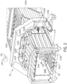
FIG. 2 is a perspective rear view of a baling chamber of the baler ofFIG. 1 . - Referring to the drawings, and more particularly to
FIG. 1 , there is shown a perspective cutaway view showing the internal workings of a largesquare baler 10 including achassis 11. Thebaler 10 operates on a two-stage feeding system. Crop material is lifted from windrows into thebaler 10 using apickup unit 12. Thepickup unit 12 includes a rotatingpickup roll 14 withtines 16 which move the crop rearward toward apacker unit 18 and/or a rotor unit. An optional pair of stub augers (one of which is shown, but not numbered) are positioned above thepickup roll 14 to move the crop material laterally inward. Thepacker unit 18 includespacker tines 20, which push the crop into apre-compression chamber 22 to form a wad of crop material. Thepacker tines 20 intertwine the crop together and pack the crop within thepre-compression chamber 22. Thepre-compression chamber 22 and the packer tines 20 function as the first stage for crop compression. Once the pressure in thepre-compression chamber 22 reaches a predetermined sensed value, astuffer unit 24 moves the wad of crop from thepre-compression chamber 22 to abale chamber 26, which is carried by thechassis 11 and may also be referred to as a "main bale chamber." Thestuffer unit 24 includesstuffer forks 28 which thrust the wad of crop directly in front of a plunger 30, which reciprocates within themain bale chamber 26 and compresses the wad of crop into a flake. The stuffer forks 28 return to their original stationary state after the wad of material has been moved into themain bale chamber 26. The plunger 30 compresses the wads of crop into flakes to form a bale and, at the same time, gradually advances the bale from aninlet end 104 of themain bale chamber 26 toward anoutlet 32 of themain bale chamber 26. Themain bale chamber 26 and the plunger 30 function as the second stage for crop compression. When enough flakes have been added and the bale reaches a full (or other predetermined) size,knotters 34 are actuated which wrap and tie twine around the bale while it is still in themain bale chamber 26.Needles 36 bring the lower twine up to theknotters 34 and the tying process then takes place. The twine is cut, and the formed bale is ejected from adischarge chute 38 as a new bale is formed. - The plunger 30 is connected via one or two crank arms 40 (only one crank arm is shown in
Figure 1 ) with agear box 42. Thegear box 42 is driven by aflywheel 44, which in turn is connected via adrive shaft 46 with the power take-off (PTO)coupler 48. ThePTO coupler 48 is detachably connected with the PTO spline at the rear of the traction unit, such as a tractor (not shown). ThePTO coupler 48, thedrive shaft 46 and theflywheel 44 together define a portion of adriveline 50, which provides rotative power to thegearbox 42. Theflywheel 44 has a sufficient mass to carry the plunger 30 through a compression stroke as power is applied to thedrive shaft 46 by the traction unit (not shown). The number of strokes performed by the plunger per minute is dependent on the PTO speed. In one example, the PTO shaft 13 rotates at a speed of around 1000 rpm such that the plunger 30 completes around 48 strokes per minute. - A
conrod 41 connecting thecrank arm 40 to thegear box 42 may be equipped with load sensors, particularly load cells that enable determination of a load force experienced by the plunger during the baling process. The load cells may, for example, be provided within the conrod bearings. Alternatively, load sensors may be provided at any other point suitable for detecting the load acting on the plunger during the various phases of the stroke. The load force is typically highest when the plunger 30 engages with the crop in thebale chamber 26. - Referring now to
FIG. 2 , a perspective view of thebale chamber 26 is illustrated. Thebale chamber 26 generally includes a plurality of stationary walls, which may include atop wall 201A, a pair ofopposed side walls 201B, and astationary bottom wall 201C opposite thetop wall 201A. As the bale flows through thebale chamber 26 in a bale forming direction, which is designated by arrow BD, the bale encountersmovable density doors movable density door 210A is a top density door that is pivotably coupled to a stationary part of the balingchamber 26 so as to form thetop wall 201A and themovable density doors chamber 26 so as to formrespective side walls 201B. A bale pressing area BP is defined between thedensity doors stationary bottom wall 201C where thedensity doors density doors density doors bale chamber 26. - To adjust the size of the bale pressing area BP, and thus the pressure exerted on the bale by the
density doors fluid cylinder density doors top density door 210A is moved by threefluid cylinders 220A and each of theside density doors fluid cylinders 220B. Each of thefluid cylinders cylinder rod density doors fluid cylinders cylinder rods fluid cylinders - When the
fluid cylinders respective density doors fluid cylinders respective density doors - A bale length sensor is provided in the
bale chamber 26 to continuously or intermittently determine the length of the bale being formed in thebale chamber 26. The bale length sensor is astar wheel 212, extending through thebottom wall 201C of thebale chamber 26. It should be appreciated that while thestar wheel 212 is illustrated as extending through thebottom wall 201C of thebale chamber 26, thestar wheel 212 may extend through any of thewalls star wheel 212 is shown in thebale chamber 26 ofFigure 2 . As the bale is pushed through thebale chamber 26, the bale engages the sprockets of thestar wheel 212 and thus moves the sprockets of thestar wheel 212 in the baling direction BD. Movement of the sprockets causes a rotation of thestar wheel 212 that is directly proportional to an extension (e.g. the length) of the bale within the baling chamber. - The knotter cycle, which must be completed to tie twine around the bale and define the length of the bale, occurs between two flakes being added to the bale. In known balers, especially small square balers, the thickness of the flakes being added to the bale may vary considerably. If the thickness of the incoming flake is unknown, the future length of the bale after adding the flake cannot be reasonably ascertained. This uncertainty is significant when the forming bale is relatively close to the defined length before the knotters activate to tie up the bale.
- To address some of the previously described issues, and referring still to
Figures 1-2 , anencoder 230 is either associated with or forms part of the bale length sensor and is operably coupled to acontroller 240, which is also operably coupled to theknotters 34 to control operation of theknotters 34. Theencoder 230 outputs rotation signals corresponding to a rotation distance of thestar wheel 212. The rotation signals may correspond to degrees of rotation of thestar wheel 212, with the degrees of rotation directly correlated to the change in length of the forming bale e.g., 5° of rotation corresponds to a smaller rotation of thestar wheel 212 and thus a smaller increase in length of the forming bale compared to 10° of rotation of thestar wheel 212. Thecontroller 240 is configured to receive the rotation signals and determine a thickness of a plurality of flakes of crop material added to the forming bale based on the received rotation signals. Thecontroller 240 is further configured to predict a probable flake thickness based on determined thicknesses of previous flakes of crop material. Once the probable flake thickness is predicted, thecontroller 240 may, for example, determine a current length of the forming bale, determine a probable length of the forming bale when the probable flake thickness is added to the forming bale, and output a knotter cycle initiation signal so the knotters tie the forming bale if the probable length of the forming bale exceeds a defined cutoff value. In this respect, thecontroller 240 can predict the probable thickness of a further flake, which will be added to the length of the bale, and determine if adding the further flake to the forming bale is likely to cause the bale to be larger than intended and thus cause theknotters 34 to tie the bale. - To predict the probable flake thickness, the
controller 240 can utilize the received rotation signals and determine the thickness of each flake of crop material added to one or more bales. The flakes of crop material are added to the bale incrementally. Thestar wheel 212 will rotate as each individual flake is added and there will likely be a momentary pause in rotation of thestar wheel 212 between each flake being added. Thecontroller 240 may be configured to determine a thickness of each flake being added to the bale by assuming that thestar wheel 212 not rotating for a defined time period corresponds to the time period where a flake is not being added to the bale. Thecontroller 240 can thus determine the thickness of each flake added to the bale by determining the rotation of thestar wheel 212 in each time period where thestar wheel 212 is rotating. In some embodiments, thecontroller 240 is configured to filter out certain events, e.g., rotation of thestar wheel 212 when the baler is traveling through headlands, in determining the thickness of each flake added to the bale. - To predict a probable flake thickness based on determined thicknesses of previous flakes of crop material, the
controller 240 may be configured, for example, to store previously determined thicknesses of previous flakes of crop material in amemory 241 and utilize statistical analysis of the previously determined thicknesses to predict the probable flake thickness. Statistical analysis may be tailored to provide a desired confidence interval. Thecontroller 240 may be configured, for example, to predict the probable flake thickness based on the measured thicknesses of previous flakes and determining a mean thickness of previous flakes. In some embodiments, thecontroller 240 may be further configured to determine a standard deviation of the thicknesses of previous flakes and add or subtract an integer number of standard deviations to the mean thickness of previous flakes to determine a maximum (or minimum) probable flake thickness. In some embodiments, thecontroller 240 is configured to determine the mean thickness of previous flakes, determine the standard deviation of the thicknesses of previous flakes, and add (or subtract) two or three standard deviations of the thicknesses of previous flakes to determine the maximum (or minimum) probable flake thickness. It should be appreciated that while thecontroller 240 may be configured to predict the probable thickness as the mean thickness of previous flakes, thecontroller 240 can be configured in many different ways to predict the probable thickness. - After the
controller 240 predicts the probable thickness, thecontroller 240 can determine whether theknotters 34 should tie the bale or not. For example, if the forming bale is at 99% of the defined bale length and thecontroller 240 predicts that the probable thickness is 5% of the defined bale length, which is likely to result in a bale being formed that is too large (104% of the defined bale length), thecontroller 240 may output the knotter cycle initiation signal to initiate the knotter cycle so theknotters 34 tie the bale. Thecontroller 240 may be configured to output the knotter cycle initiation signal if the probable length of the forming bale when the probable flake thickness is added to the forming bale deviates from a defined bale length by more than a defined deviation amount. The defined deviation amount may be adjustable by a user so the tied bales are likely to conform to the user's desired bale length. Thecontroller 240 may also be configured to output the knotter cycle initiation signal if a maximum probable length of the forming bale, which is equal to the maximum probable flake thickness added to the current bale length, exceeds the defined bale length. Thecontroller 240 may also be configured with bale length protection by being configured to not output the knotter cycle initiation signal if a minimum probable length of the forming bale, which is equal to the minimum probable flake thickness added to the current bale length, is below a defined minimum length value. - The present invention also provides a method for forming bales. The method includes adding a plurality of flakes to one or more bales, determining a thickness of each of the flakes added to the one or more bales, and predicting a probable flake thickness based on the determined thickness of each of the flakes added to the one or more bales. The probable flake thickness may be used to determine if a knotter cycle should be initiated prior to adding another flake of crop material to a bale forming in a bale chamber.
- It should be appreciated that while the
baler 10 is illustrated and described as being what is commonly referred to as a "large square baler," the present invention also provides a small square baler that includes knotters and a bale length sensor (such as a star wheel) extending into a bale chamber along with the previously describedcontroller 240 and theencoder 230. An exemplary small square baler is described inU.S. Patent No. 7,707,932 . - From the foregoing, it should be appreciated that the baler provided according to the present invention has a controller that can predict the probable thickness of flakes of crop material, which allows the controller to also predict the probable length of the forming bale after another flake is added to the bale. Based off this prediction, the controller can determine if the knotter cycle should initiate prior to the normal setpoint, which would be activated by the bale reaching a defined length as measured by the bale length sensor.
- It is to be understood that the above-described operating steps are performed by the
controller 240 upon loading and executing software code or instructions which are tangibly stored on a tangible computer readable medium, such as on a magnetic medium, e.g., a computer hard drive, an optical medium, e.g., an optical disc, solid-state memory, e.g., flash memory, or other storage media known in the art. Thus, any of the functionality performed by thecontroller 240 described herein, such as the aforementioned method of operation, is implemented in software code or instructions which are tangibly stored on the tangible computer readable medium. Upon loading and executing such software code or instructions by thecontroller 240, thecontroller 240 may perform any of the functionality of thecontroller 240 described herein, including any steps of the aforementioned method described herein.
Claims (15)
- An agricultural baler (10) comprising:a main bale chamber (26) in which crop material is compressed into bales, the main bale chamber (26) comprising an inlet (104) for receiving a wad of crop material from a pre-compression chamber of the agricultural baler, and an outlet (32) for discharge of compressed crop material into a completed bale formed by a plurality of flakes that are incrementally added together; anda bale length sensor (212, 230) that is configured to determine a current length of one bale as the bale is being formed in the main bale chamber;wherein the agricultural baler (10) further comprises a controller (240) that is configured to estimate a completed length of the bale during formation of the bale based on:(i) the current length of the bale being formed; and(ii) a predicted thickness of an impending flake to be added to the bale.
- The agricultural baler of claim 1, wherein the bale length sensor is a rotatable star-wheel (212) that is mounted in the main bale chamber (26).
- The agricultural baler (10) of claim 2, further comprising a rotary encoder (230) that is operatively coupled to the star-wheel (212), the rotary encoder (230) being configured to output rotation signals to the controller (240), the rotation signals corresponding to a rotation of the star-wheel (212).
- The agricultural baler (10) of claim 3, wherein the controller (240) is configured to calculate the current length of the bale as a function of the rotation signals of the rotary encoder (230).
- The agricultural baler (10) of any one of the preceding claims, further comprising a knotter (34) that is configured to wrap and tie twine around a formed bale in the main bale chamber (26).
- The agricultural baler (10) of claim 5, wherein the controller (240) is configured to activate the knotter (34) to wrap and tie twine around the formed bale in the main bale chamber (26) once the controller (240) calculates that the completed length estimate is within a pre-determined range.
- The agricultural baler (10) of any one of the preceding claims, wherein the controller (240) is configured to calculate the predicted thickness based on a thickness of the immediately preceding flake, as measured by the bale length sensor.
- The agricultural baler (10) of any one of claims 1-6, wherein the controller (240) is configured to calculate the predicted thickness based on a mean thickness of multiple preceding flakes, as measured by the bale length sensor.
- The agricultural baler (10) of any one of claims 1-6, wherein the controller (240) is configured to calculate the predicted thickness based on a mean thickness of multiple preceding flakes, as measured by the bale length sensor (212, 230), and the controller (240) is further configured to calculate a standard deviation of the thicknesses of the multiple preceding flakes.
- The agricultural baler (10) of claim 9, wherein the controller (240) is configured to either add or subtract the standard deviation to the mean thickness to determine the predicted thickness of the impending flake as either a maximum or minimum value, respectively.
- The agricultural baler (10) of claim 9, wherein the controller (240) is configured to calculate either two or three standard deviations of the thicknesses of the multiple preceding flakes, and either add or subtract the two or three standard deviations to the mean thickness to determine the predicted thickness of the impending flake as either a maximum or minimum value, respectively.
- The agricultural baler (10) of claim 9, wherein the controller (240) comprises a memory (241) for storing the current length and a measured thickness of each of the multiple preceding flakes.
- The agricultural baler (10) of any one of the preceding claims, wherein in calculating the predicted thickness, the controller (240) is configured to filter out signals transmitted by the bale length sensor (212, 230) during events including headland travel.
- The agricultural baler (10) of any one of the preceding claims, further comprising a plunger (30) that is configured for compressing the crop material within the main bale chamber (26).
- An agricultural vehicle comprising a tractor and the agricultural baler (10) of any one of the preceding claims mounted to the tractor.
Applications Claiming Priority (1)
| Application Number | Priority Date | Filing Date | Title |
|---|---|---|---|
| US202263349812P | 2022-06-07 | 2022-06-07 |
Publications (1)
| Publication Number | Publication Date |
|---|---|
| EP4289257A1 true EP4289257A1 (en) | 2023-12-13 |
Family
ID=86732541
Family Applications (1)
| Application Number | Title | Priority Date | Filing Date |
|---|---|---|---|
| EP23178085.9A Pending EP4289257A1 (en) | 2022-06-07 | 2023-06-07 | Agricultural baler with flake prediction for bale length control |
Country Status (2)
| Country | Link |
|---|---|
| US (1) | US20230392917A1 (en) |
| EP (1) | EP4289257A1 (en) |
Citations (6)
| Publication number | Priority date | Publication date | Assignee | Title |
|---|---|---|---|---|
| US7707932B1 (en) | 2009-05-05 | 2010-05-04 | Cnh America Llc | Staggered plunger tail with improved wear surface for a small square baler |
| US20180125011A1 (en) * | 2016-11-10 | 2018-05-10 | Deere & Company | Large square baler, combination of an agricultural towing vehicle with such, and a method for operating such |
| US20180228091A1 (en) | 2017-02-10 | 2018-08-16 | Cnh Industrial America Llc | Agricultural Baler with Extended Bale Ejection System |
| US10542679B2 (en) * | 2015-03-24 | 2020-01-28 | Animal Health International, Inc. | Device and method for tracking and marking baled forage material |
| EP3818815A1 (en) | 2019-11-08 | 2021-05-12 | CNH Industrial Belgium NV | Agricultural baler |
| AU2021205022A1 (en) * | 2019-01-09 | 2021-08-12 | Great Plains Manufacturing, Inc. | High capacity baler |
Family Cites Families (7)
| Publication number | Priority date | Publication date | Assignee | Title |
|---|---|---|---|---|
| BE1020292A3 (en) * | 2011-11-09 | 2013-07-02 | Cnh Belgium Nv | SQUARE BALL PRESS WITH STAR WHEEL SENSOR. |
| BE1022402B1 (en) * | 2013-11-22 | 2016-03-24 | Cnh Belgium N.V. | BALL MEASURING SYSTEM AND METHOD |
| US10477775B2 (en) * | 2014-09-29 | 2019-11-19 | Deere & Company | Baler mass flow sensing assembly and method |
| US10334788B2 (en) * | 2014-09-29 | 2019-07-02 | Deere & Company | Baler with mass flow sensing assembly and method of initiating stuffer trip |
| US11140830B2 (en) * | 2019-01-09 | 2021-10-12 | Great Plains Manufacturing, Inc. | High capacity baler with multiple knotters |
| US11231317B2 (en) * | 2019-08-20 | 2022-01-25 | Cnh Industrial America Llc | Systems and methods for filtering sensor signal interference deriving from powered components of a header |
| IT201900023379A1 (en) * | 2019-12-09 | 2021-06-09 | Cnh Ind Italia Spa | SYSTEM AND METHOD FOR ESTIMATING THE LENGTH OF A BALL OF MATERIAL COLLECTED DURING THE FORMATION OF A BALE |
-
2023
- 2023-06-02 US US18/205,111 patent/US20230392917A1/en active Pending
- 2023-06-07 EP EP23178085.9A patent/EP4289257A1/en active Pending
Patent Citations (6)
| Publication number | Priority date | Publication date | Assignee | Title |
|---|---|---|---|---|
| US7707932B1 (en) | 2009-05-05 | 2010-05-04 | Cnh America Llc | Staggered plunger tail with improved wear surface for a small square baler |
| US10542679B2 (en) * | 2015-03-24 | 2020-01-28 | Animal Health International, Inc. | Device and method for tracking and marking baled forage material |
| US20180125011A1 (en) * | 2016-11-10 | 2018-05-10 | Deere & Company | Large square baler, combination of an agricultural towing vehicle with such, and a method for operating such |
| US20180228091A1 (en) | 2017-02-10 | 2018-08-16 | Cnh Industrial America Llc | Agricultural Baler with Extended Bale Ejection System |
| AU2021205022A1 (en) * | 2019-01-09 | 2021-08-12 | Great Plains Manufacturing, Inc. | High capacity baler |
| EP3818815A1 (en) | 2019-11-08 | 2021-05-12 | CNH Industrial Belgium NV | Agricultural baler |
Also Published As
| Publication number | Publication date |
|---|---|
| US20230392917A1 (en) | 2023-12-07 |
Similar Documents
| Publication | Publication Date | Title |
|---|---|---|
| US10292335B2 (en) | Signal processing method of a bale chamber load signal | |
| US9861041B2 (en) | Load sensor for an agricultural baler | |
| US10194591B2 (en) | Stuffer unit for an agricultural baler with automatic density control | |
| EP3075225B1 (en) | Pickup unit with a windrow conditioning roll for an agricultural baler | |
| EP3726958B1 (en) | Baler with nir sensor in plunger face | |
| US10327388B2 (en) | Agricultural baler with extended bale ejection system | |
| EP3157320B1 (en) | Agricultural baler with a common drive powering the plunger and the needles with an integrated safety | |
| US20070245704A1 (en) | Yield monitor system | |
| US10143142B2 (en) | Agricultural baler with auxiliary power system | |
| US20230392917A1 (en) | Agricultural baler with flake prediction for bale length control | |
| US11964526B2 (en) | Height adjustment arrangement for an agricultural baler | |
| US12593755B2 (en) | Agricultural baler with remote bale length control | |
| US11974521B2 (en) | Bale chamber arrangement for an agricultural baler | |
| EP2962543B1 (en) | Plunger for a square baler | |
| EP3513647B1 (en) | Strawhook arrangement for an agricultural baler | |
| EP3305059B1 (en) | Plunger slot cleaner for an agricultural baler | |
| EP3038454B1 (en) | Stuffer trigger system for an agricultural baler | |
| EP3834603A1 (en) | System and method for estimating the length of a crop material bale during bale formation |
Legal Events
| Date | Code | Title | Description |
|---|---|---|---|
| PUAI | Public reference made under article 153(3) epc to a published international application that has entered the european phase |
Free format text: ORIGINAL CODE: 0009012 |
|
| STAA | Information on the status of an ep patent application or granted ep patent |
Free format text: STATUS: THE APPLICATION HAS BEEN PUBLISHED |
|
| AK | Designated contracting states |
Kind code of ref document: A1 Designated state(s): AL AT BE BG CH CY CZ DE DK EE ES FI FR GB GR HR HU IE IS IT LI LT LU LV MC ME MK MT NL NO PL PT RO RS SE SI SK SM TR |
|
| STAA | Information on the status of an ep patent application or granted ep patent |
Free format text: STATUS: REQUEST FOR EXAMINATION WAS MADE |
|
| 17P | Request for examination filed |
Effective date: 20240613 |
|
| RBV | Designated contracting states (corrected) |
Designated state(s): AL AT BE BG CH CY CZ DE DK EE ES FI FR GB GR HR HU IE IS IT LI LT LU LV MC ME MK MT NL NO PL PT RO RS SE SI SK SM TR |
|
| GRAP | Despatch of communication of intention to grant a patent |
Free format text: ORIGINAL CODE: EPIDOSNIGR1 |
|
| STAA | Information on the status of an ep patent application or granted ep patent |
Free format text: STATUS: GRANT OF PATENT IS INTENDED |
|
| RIC1 | Information provided on ipc code assigned before grant |
Ipc: A01F 15/08 20060101AFI20260323BHEP Ipc: A01F 15/14 20060101ALI20260323BHEP |