EP4289245A1 - Press wheel and method of manufacturing such - Google Patents
Press wheel and method of manufacturing such Download PDFInfo
- Publication number
- EP4289245A1 EP4289245A1 EP23178083.4A EP23178083A EP4289245A1 EP 4289245 A1 EP4289245 A1 EP 4289245A1 EP 23178083 A EP23178083 A EP 23178083A EP 4289245 A1 EP4289245 A1 EP 4289245A1
- Authority
- EP
- European Patent Office
- Prior art keywords
- rim
- wheel
- press wheel
- axially
- outer rim
- Prior art date
- Legal status (The legal status is an assumption and is not a legal conclusion. Google has not performed a legal analysis and makes no representation as to the accuracy of the status listed.)
- Granted
Links
Images




Classifications
-
- A—HUMAN NECESSITIES
- A01—AGRICULTURE; FORESTRY; ANIMAL HUSBANDRY; HUNTING; TRAPPING; FISHING
- A01C—PLANTING; SOWING; FERTILISING
- A01C5/00—Making or covering furrows or holes for sowing, planting or manuring
- A01C5/06—Machines for making or covering drills or furrows for sowing or planting
- A01C5/066—Devices for covering drills or furrows
- A01C5/068—Furrow packing devices, e.g. press wheels
Definitions
- the present disclosure generally relates to press wheels, and more particularly but not exclusively relates to mobile agricultural equipment including one or more press wheels.
- Press wheels are commonly used in mobile agricultural equipment to press distributed agricultural product (e.g., seed) into a furrow.
- distributed agricultural product e.g., seed
- many conventional press wheels suffer from certain drawbacks and limitations. For example, when the ground being seeded is muddy, mud sticking to the press wheel may actually pull seed out of the furrow. For these reasons among others, there remains a need for further improvements in this technological field.
- Certain embodiments of the present application relate to a press wheel for agricultural equipment, the press wheel comprising: an annular inner rim extending along a rotational axis and defining a central opening; and a wheel body circumferentially surrounding the inner rim; wherein the inner rim comprises a plurality of axially-extending recesses.
- the inner rim might have a first side and a second side opposite the first side.
- the plurality of axially-extending recesses may comprise a plurality of first axially-extending recesses and a plurality of second axially-extending recesses; wherein each of the first axially-extending recesses extends from the first side toward the second side; and wherein each of the second axially-extending recesses extends from the second side toward the first side.
- the first axially-extending recesses and the second axially-extending recesses may alternate about a circumference of the inner rim.
- the inner rim may comprise a serpentine shape defined at least in part by the plurality of axially-extending recesses.
- the wheel body may comprises a plurality of ridges; and wherein the plurality of ridges are received in and engaged with the plurality of axially-extending recesses.
- each of the axially-extending recesses may be formed as an axially-extending slot.
- the wheel body may comprise an elastomeric material.
- the press wheel may comprise a bearing positioned in the central opening and forming a press fit with the inner rim.
- the press wheel may comprise an outer rim circumferentially surrounding the wheel body; wherein the outer rim comprises urethane and/or ultra-high molecular weight polyethylene.
- Another embodiment of the present application relates to a method of manufacturing a press wheel for agricultural equipment, the method comprising: over-molding a wheel body onto at least one additional component, wherein the at least one additional component comprises an outer rim; wherein the outer rim comprises a plastic material; and wherein the wheel body comprises an elastomeric material.
- the plastic material may comprise urethane and/or ultra-high molecular weight polyethylene.
- the at least one additional component may further comprise an inner rim; wherein the inner rim comprises a plurality of recesses; and wherein the over-molding forms the wheel body with a plurality of ridges received in and engaged with the plurality of recesses.
- the outer rim may comprise: a rim body; and a plurality of flanges projecting inward from the rim body.
- One or more of the flanges may comprise one or more openings; and wherein the over-molding forms the wheel body with one or more projections received in the one or more openings.
- one or more of the flanges extends axially, and partially defines a face of the press wheel.
- the method may further comprise, prior to over-molding the wheel body onto the at least one additional component, forming the outer rim of a plurality of modular segments.
- Forming the outer rim may comprise interlocking one or more of the modular segments with an adjacent one of the modular segments.
- the at least one additional component may comprise an inner rim; and wherein forming the outer rim comprises interlocking one or more of the modular segments with the inner rim.
- the method may further comprise: inserting a bearing into a central aperture of the wheel body; and capturing an outer portion of the bearing and an inner portion of the wheel body between a pair of interlocking pieces, thereby coupling the bearing with the wheel body.
- references in the specification to "one embodiment,” “an embodiment,” “an illustrative embodiment,” etc., indicate that the embodiment described may include a particular feature, structure, or characteristic, but every embodiment may or may not necessarily include that particular feature, structure, or characteristic. Moreover, such phrases are not necessarily referring to the same embodiment. It should further be appreciated that although reference to a "preferred" component or feature may indicate the desirability of a particular component or feature with respect to an embodiment, the disclosure is not so limiting with respect to other embodiments, which may omit such a component or feature. Further, when a particular feature, structure, or characteristic is described in connection with an embodiment, it is submitted that it is within the knowledge of one skilled in the art to implement such feature, structure, or characteristic in connection with other embodiments whether or not explicitly described.
- items included in a list in the form of "at least one of A, B, and C” can mean (A); (B); (C); (A and B); (B and C); (A and C); or (A, B, and C).
- items listed in the form of "at least one of A, B, or C” can mean (A); (B); (C); (A and B); (B and C); (A and C); or (A, B, and C).
- Items listed in the form of "A, B, and/or C” can also mean (A); (B); (C); (A and B); (B and C); (A and C); or (A, B, and C).
- the seeder 100 generally includes a frame 110, one or more reservoirs 120 operable to hold an agricultural product (e.g., seed), and a plurality of row units 130 mounted to the frame 110. As described herein, the seeder 100 is configured to form furrows 90 in the ground, each furrow 90 being provided with agricultural product from the reservoir 120 via the row units 130.
- an agricultural product e.g., seed
- Each row unit 130 includes one or more components to perform corresponding operations for the process of forming and seeding the furrows 90.
- each row unit 130 generally includes an opening disk 132 that opens the furrow 90, a distribution unit 134 that distributes seed into the opened furrow 90, a press wheel 136 that presses the seed into the furrow 90, and a closing wheel 138 that covers the seed and closes the furrow 90.
- the press wheel assembly 200 may, for example, be provided in one or more of the row units 130 of the above-described seeder 100.
- the press wheel assembly 200 generally includes a frame 210 and a press wheel 220 rotatably mounted to the frame 210.
- the press wheel assembly 200 is provided in a retracted configuration, in which the press wheel 220 is retracted to a position adjacent the frame 210. From this configuration, the press wheel assembly 200 may be moved to a deployed configuration, in which the press wheel 220 is positioned generally below and/or behind the frame 210.
- the press wheel 300 may, for example, be utilized in the press wheel assembly 200 and/or as the press wheel 136 of the above-described row units 130.
- the press wheel 300 is rotatable about a rotational axis 301, and generally includes an outer rim 310, an inner rim 320, and a body portion 330 extending between and connecting the outer rim 310 and the inner rim 320.
- the press wheel 300 further includes a bearing 340 that facilitates the rotational coupling of the wheel 300 to a frame (e.g., the frame 210).
- the outer rim 310 and the wheel body 330 are integrally formed as a monolithic or single-piece construction. As described herein, it is also contemplated that the outer rim 310 may be one or more distinct components to which the wheel body 330 is attached.
- the inner rim 320 of the illustrated press wheel 300 is generally annular, and has a serpentine configuration about its circumference.
- the inner rim 320 has a central opening 321, a first axial side 322 and an axially-opposite second side 324, and recesses in the form of slots 326, 326' alternatingly extend from the two sides 322, 324 to at least partially define the serpentine structure of the inner rim 320. More particularly, first slots 326 extend axially from the first axial side 322 toward the second axial side 324, and second slots 326 extend axially from the second axial side 324 toward the first axial side 322.
- this serpentine configuration may serve one or more functions for the press wheel 300, such as providing greater tolerances and/or reducing relative axial movement of the inner rim 320 and wheel body 330.
- the inner rim 320 may be formed of a metal material, such as steel.
- the wheel body 330 is somewhat flexible, and may, for example, be formed of an elastomeric material. In certain embodiments, the wheel body 330 is over-molded onto the outer rim 310 and/or the inner rim 320. Additionally or alternatively, the wheel body 330 may be connected to the outer rim 310 and/or the inner rim 320 via mechanical and/or chemical fasteners. As one example, a bonding agent may provide a chemical adhesion between the wheel body 330 and at the outer rim 310 and/or the inner rim 320. In certain embodiments, at least a portion of the wheel body 330 may be hollow. In certain embodiments, the wheel body 330 may be solid and substantially without hollow portions.
- the wheel body 330 may be provided with ridges 336 corresponding to the slots 326 of the inner rim 320. These ridges 336 engage the slots 326 and discourage relative axial shifting of the inner rim 320 and wheel body 330.
- the slots 326 also render the inner rim 320 more flexible than a truly annular inner rim would be, which may provide for increased tolerances for pressfitting the bearing 340 into the central opening of the inner rim 320.
- the outer rim 310 and the wheel body 330 are provided as a single-piece construction.
- this single-piece construction may, for example, be formed by injecting a liquid elastomeric composition into an appropriately-shaped mold.
- the liquid composition may be mixed with a plastic powder that renders the resulting outer rim 310 and/or wheel body 330 less susceptible to having mud and other debris stick thereon.
- at least some of the elastomeric composition may be mixed with ultra-high molecular weight polyethylene (UHMWPE) powder.
- UHMWPE ultra-high molecular weight polyethylene
- the UHMWPE powder may be at least 5% of the total weight of the mixture, at least 10% of the total weight of the mixture, at least 20% of the total weight of the mixture, at least 30% of the total weight of the mixture, at least 40% of the total weight of the mixture, at least 50% of the total weight of the mixture, or at least 60% of the total weight of the mixture. Additionally, it is also contemplated that such a mixture may be utilized to form the wheel bodies of other embodiments described herein.
- a press wheel 400 illustrated therein is a press wheel 400 according to certain embodiments.
- the press wheel 400 may, for example, be utilized in the press wheel assembly 200 and/or as the press wheel 136 of the above-described row units 130.
- the press wheel 400 is substantially similar to the press wheel 300 illustrated in Fig. 3 and 4 , and similar reference characters are used to indicate similar elements and features.
- the press wheel 400 generally includes an outer rim 410, an inner rim 420, and a body portion 430, which respectively correspond to the outer rim 310, the inner rim 320, and the body portion 330 of the above-described press wheel 300.
- the following description of the press wheel 400 focuses primarily on elements and features that are different from those described above with reference to the press wheel 300.
- the outer rim 410 is defined by at least one discrete component to which the wheel body 430 is attached, for example by over-molding.
- the outer rim 410 is formed of a material different from that utilized for the wheel body 430.
- the outer rim 410 may be formed of a material that is harder than the relatively softer material utilized for the wheel body 430.
- the outer rim 410 may, for example, be provided with a Shore A hardness rating of between 40 and 70, such as a hardness of about 60 Shore A (e.g., between 55 Shore A and 65 Shore A).
- the outer rim 410 may be formed of a plastic material, such as urethane, polyurethane, polyethylene, and/or ultra-high molecular weight polyethylene (UHMWPE).
- the outer rim 410 generally includes a rim body 412 and a plurality of flanges 414 projecting radially inward from the rim body 412.
- the rim body 412 is generally annular, and has a smooth and curved outer surface 413.
- One or more of the flanges 414 may include an aperture or opening 415 into which material of the wheel body 430 may flow during the over-molding process to mechanically secure the wheel body 430 to the outer rim 410.
- the wheel body 430 may be formed of a mixture including an elastomeric material and UHMWPE powder as described above.
- a press wheel 500 illustrated therein is a press wheel 500 according to certain embodiments.
- the press wheel 500 may, for example, be utilized in the press wheel assembly 200 and/or as the press wheel 136 of the above-described row units 130.
- the press wheel 500 is substantially similar to the press wheel 400 illustrated in Fig. 5 , and similar reference characters are used to indicate similar elements and features.
- the press wheel 500 generally includes an outer rim 510, an inner rim 520, and a body portion 530, which respectively correspond to the outer rim 410, the inner rim 420, and the body portion 430 of the above-described press wheel 400.
- the following description of the press wheel 500 focuses primarily on elements and features that are different from those described above with reference to the press wheel 400.
- the outer rim 510 generally includes a rim body 512 and a plurality of flanges 514 projecting radially inward from the rim body 512.
- the flanges 514 are generally T-shaped, which may aid in mechanically securing the wheel body 530 to the outer rim 510.
- a press wheel 600 illustrated therein is a press wheel 600 according to certain embodiments.
- the press wheel 600 may, for example, be utilized in the press wheel assembly 200 and/or as the press wheel 136 of the above-described row units 130.
- the press wheel 600 is substantially similar to the press wheel 400 illustrated in Fig. 6 , and similar reference characters are used to indicate similar elements and features.
- the press wheel 600 generally includes an outer rim 610, an inner rim 620, and a body portion 630, which respectively correspond to the outer rim 410, the inner rim 420, and the body portion 430 of the above-described press wheel 400.
- the following description of the press wheel 600 focuses primarily on elements and features that are different from those described above with reference to the press wheel 400.
- the outer rim 610 generally includes a rim body 612 and a plurality of flanges 614 projecting radially inward from the rim body 612.
- each of the flanges 614 includes a pair of apertures 615, which may aid in mechanically securing the wheel body 630 to the outer rim 610.
- material may flow into the apertures 615 during the over-molding process to thereby form projections within the wheel body 630.
- a press wheel 700 illustrated therein is a press wheel 700 according to certain embodiments.
- the press wheel 700 may, for example, be utilized in the press wheel assembly 200 and/or as the press wheel 136 of the above-described row units 130.
- the press wheel 700 is substantially similar to the press wheel 400 illustrated in Fig. 5 , and similar reference characters are used to indicate similar elements and features.
- the press wheel 700 generally includes an outer rim 710, an inner rim 720, and a body portion 730, which respectively correspond to the outer rim 410, the inner rim 420, and the body portion 430 of the above-described press wheel 400.
- the following description of the press wheel 700 focuses primarily on elements and features that are different from those described above with reference to the press wheel 400.
- the outer rim 710 generally includes a rim body 712 and a plurality of flanges 714 projecting radially inward from the rim body 712.
- Each flange 714 includes a pair of axially-projecting lobes 716 that project to the axially-outer surface of the press wheel 700 and partially define a face of the press wheel 700.
- these lobes 716 may discourage detritus (e.g., mud) from sticking to the sidewalls of the press wheel 700.
- the outer rim 800 includes a rim body 802 and may, for example, be utilized in a press wheel along the lines described above. As one example, the outer rim 800 may be utilized in the press wheel 400 illustrated in Fig. 5 in place of the outer rim 410. As described herein, the illustrated outer rim 800 is formed of a plurality of discrete modular segments 810.
- the modular segment 810 includes a rim body segment 812 and a flange 814 projecting inward from the rim body segment 812.
- the flange 814 includes one or more recesses 815 that may aid in mechanically coupling the segment 812 to a wheel body that is over-molded onto the outer rim 800, and in the illustrated form further includes a tongue 816 and a groove 818 having a shape complementary to that of the tongue 816.
- the outer rim 800 may, for example, be assembled by arranging a plurality of the modular segments 810 such that the arcuate body segments 812 form a generally annular outer rim body while interlocking the tongue 816 of each segment 810 with the groove 818 of an adjacent segment 810.
- the outer rim 800, and optionally an inner rim along the lines of the inner rim 320, may then be over-molded with an elastomeric material to form the wheel body of a press wheel.
- the outer rim 900 includes a rim body 902 and may, for example, be utilized in a press wheel along the lines described above. As one example, the outer rim 900 may be utilized in the press wheel 400 illustrated in Fig. 5 in place of the outer rim 410. As described herein, the illustrated outer rim 900 is formed of a plurality of discrete modular segments 910.
- the modular segment 910 includes a rim body segment 912 and a flange 914 projecting inward from the rim body segment 912.
- the flange 914 includes one or more recesses 915 that may aid in mechanically coupling the segment 912 to a wheel body that is over-molded onto the outer rim 900, and in the illustrated form further includes a neck 916 that extends to a head 918 including a pair of shoulders 919.
- the outer rim 900 may, for example, be assembled by arranging a plurality of the modular segments 910 such that the body segments 912 form a generally annular outer rim body while interlocking the flange 914 of each segment 910 with the inner rim 320.
- the neck 916 of each segment 910 may be inserted into a corresponding slot 326, 326' of the inner rim 320 such that the shoulders 919 restrict movement of the segment 910 relative to the inner rim 320.
- the outer rim 900 and the inner rim 320 may then be over-molded with an elastomeric material (which may include UHMWPE powder) to form at least a portion of a press wheel. After the over-molding process is complete such that the wheel body secures the segments 910 in place, the heads 918 may be trimmed from the inner perimeter to provide space for insertion of a bearing.
- the press wheel 1000 may, for example, be utilized in the press wheel assembly 200 and/or as the press wheel 136 of the above-described row units 130.
- the press wheel 1000 generally includes an outer rim 1010, an inner rim 1020, and a wheel body 1030.
- the outer rim 1010 is integrally formed with the wheel body 1030. It is also contemplated that the outer rim 1010 may be formed as a separate component, and that the wheel body 1030 may be over-molded onto such a separate component.
- the outer rim 1010 may, by way of example, be provided in any of the forms described above with reference to Figs. 5-16 .
- the inner rim 1020 is annular, and projects axially beyond the faces of the wheel body 1030, which may be over-molded onto the inner rim 1020.
- a bearing 1040 may then be inserted into the central opening 1021 of the inner rim 1020, and the edges of the inner rim 1020 may be deformed radially inward to capture the outer race 1042 of the bearing 1040 between two lips 1024.
- the press wheel 1100 may, for example, be utilized in the press wheel assembly 200 and/or as the press wheel 136 of the above-described row units 130.
- the press wheel 1100 generally includes an outer rim 1110, an inner rim 1120, and a wheel body 1130.
- the outer rim 1110 is integrally formed with the wheel body 1130. It is also contemplated that the outer rim 1110 may be formed as a separate component, and that the wheel body 1130 may be over-molded onto such a separate component.
- the outer rim 1110 may be provided in any of the forms described above with reference to Figs. 5-16 .
- the inner rim 1120 comprises a pair of interlocked components.
- the interlocked components include a first component 1121 and a second component 1125, which interlock with one another via an interlock mechanism 1129.
- the first component 1121 includes an annular projection 1122 that is received in an annular groove 1132 of the wheel body 1130 to discourage relative radial shifting of the first component 1121 and the wheel body 1130.
- the second component 1125 may include an annular projection 1126 that is received in an annular groove 1136 of the wheel body 1130 to discourage relative radial shifting of the second component 1125 and the wheel body 1130.
- the first component 1121 includes a female boss 1123
- the second component 1125 includes a male boss 1127 sized and shaped to be received in the female boss 1123.
- the outer side of the female boss 1123 generally conforms to the inner periphery of the wheel body 1130
- the inner side of the male boss 1127 generally conforms to the outer periphery of a bearing 1140.
- the inner side of the female boss 1123 includes one or more first engagement features 1124 of the interlock mechanism 1129
- the outer side of the male boss 1127 includes one or more second engagement features 1128 of the interlock mechanism 1129.
- the interlock mechanism 1129 is configured to at least selectively interlock the first component 1121 with the second component 1125 to thereby capture the bearing 1140 within the inner rim 1120.
- the engagement features 1124, 1128 are configured to snap into engagement with one another as the male boss 1127 is inserted into the female boss 1123. It is also contemplated that the interlock mechanism 1129 may be configured to interlock the components 1121, 1125 in another manner.
- the engagement features 1124, 1128 may be provided in the form of threads, and the male boss 1127 may screw into the female boss 1123.
- one or more of the engagement features on each side of the interlock mechanism 1129 may include gaps 1124' which, when aligned, reduce the force required to axially separate the two components 1121, 1125.
- the interlock mechanism 1129 may be provided in a form in which a quarter turn aligns the gaps 1124' to facilitate separation of the two components 1121, 1125.
- a press wheel 1200 illustrated therein is a press wheel 1200 according to certain embodiments.
- the press wheel 1200 may, for example, be utilized in the press wheel assembly 200 and/or as the press wheel 136 of the above-described row units 130. While not specifically illustrated in Fig. 21 , it should be appreciated that the outer rim 1210 of the press wheel 1200 may be provided along the lines of the outer rims described with reference to Figs. 5-16 , or may be integrally formed with the wheel body 1230.
- the press wheel 1200 generally includes a wheel body 1230 and a bearing 1240 seated in a central opening 1231 of the wheel body 1230.
- the wheel body 1230 is provided with (e.g., integrally formed with) a plurality of lips 1234, each of which projects beyond the outer periphery of the central opening 1231 to partially enclose the central opening 1231.
- the bearing 1240 may be inserted into the central opening 1231 such that the lips 1234 axially retain the bearing 1240 within the opening 1231.
- the process 1300 may begin with block 1310, which generally involves forming an outer rim of a press wheel.
- the outer rim may, for example, be formed of a plastic material, such as UHMWPE or a material comprising UHMWPE.
- block 1310 may involve forming the outer rim as a single-piece construction, for example by molding the outer rim. It is also contemplated that block 1310 may involve forming the outer rim from a plurality of modular segments.
- block 1310 may include block 1312, which generally involves forming a plurality of discrete modular segments.
- block 1312 may involve forming each modular segment with a rim body segment and a flange projecting inward from the rim body segment.
- Block 1310 may further involve block 1314, which generally involves interlocking each modular segment with another component to form the outer rim.
- the component with which the modular segment is interlocked in block 1314 may be another modular component.
- each modular segment 810 may be interlocked with adjacent modular segments via engagement of the tongues 816 and grooves 818.
- the component with which the modular segment is interlocked may be an inner rim.
- the heads 918 may be positioned in the central opening 321 of the inner rim 320 such that the neck 916 extends through one of the slots 326, 326'.
- the process 1300 may include block 1320, which generally involves over-molding a wheel body onto at least one additional component.
- the at least one additional component comprises an outer rim, such as the outer rim formed in block 1320.
- the at least one additional component may comprise an inner rim, such as the inner rim 320 illustrated in Fig. 4 .
- the inner rim includes a plurality of recesses (e.g., slots 326, 326') such that the over-molding process results in one or more ridges 336 received in and engaged with the recesses.
- the outer rim onto which the wheel body is over-molded may include a rim body and a plurality of flanges projecting inward from the rim body.
- one or more of the flanges may include openings (e.g., the openings 415 in the outer rim 410 illustrated in Fig. 6 ) such that the over-molding forms the wheel body with one or more projections that extend into the openings.
- one or more of the flanges may extend axially and partially define a face of the press wheel, for example as illustrated in Figs. 11 and 12 .
- the process 1300 may include block 1330, which generally involves installing a bearing to the press wheel.
- block 1330 may include block 1332, which generally involves inserting the bearing into a central aperture of the wheel body.
- Block 1330 may also include block 1334, which generally involves capturing a radially outer portion of the bearing and a radially inner portion of the wheel body between a pair of interlocking pieces, thereby coupling the bearing with the wheel body.
- block 1334 may involve capturing the outer race of the bearing 1140 and a portion of the wheel body 1130 between the interlocking components 1121, 1125 of the inner rim 1120 illustrated in Figs. 19 and 20 .
Landscapes
- Life Sciences & Earth Sciences (AREA)
- Soil Sciences (AREA)
- Environmental Sciences (AREA)
- Tires In General (AREA)
- Structures Of Non-Positive Displacement Pumps (AREA)
Abstract
Description
- The present disclosure generally relates to press wheels, and more particularly but not exclusively relates to mobile agricultural equipment including one or more press wheels.
- Press wheels are commonly used in mobile agricultural equipment to press distributed agricultural product (e.g., seed) into a furrow. However, many conventional press wheels suffer from certain drawbacks and limitations. For example, when the ground being seeded is muddy, mud sticking to the press wheel may actually pull seed out of the furrow. For these reasons among others, there remains a need for further improvements in this technological field.
- Certain embodiments of the present application relate to a press wheel for agricultural equipment, the press wheel comprising: an annular inner rim extending along a rotational axis and defining a central opening; and a wheel body circumferentially surrounding the inner rim; wherein the inner rim comprises a plurality of axially-extending recesses.
- The inner rim might have a first side and a second side opposite the first side. The plurality of axially-extending recesses may comprise a plurality of first axially-extending recesses and a plurality of second axially-extending recesses; wherein each of the first axially-extending recesses extends from the first side toward the second side; and wherein each of the second axially-extending recesses extends from the second side toward the first side.
- The first axially-extending recesses and the second axially-extending recesses may alternate about a circumference of the inner rim.
- The inner rim may comprise a serpentine shape defined at least in part by the plurality of axially-extending recesses. The wheel body may comprises a plurality of ridges; and wherein the plurality of ridges are received in and engaged with the plurality of axially-extending recesses.
- The inner rim might be chemically bonded to the wheel body. Alternatively, each of the axially-extending recesses may be formed as an axially-extending slot. In certain embodiments, the wheel body may comprise an elastomeric material.
- Further, the press wheel may comprise a bearing positioned in the central opening and forming a press fit with the inner rim.
- Further, the press wheel may comprise an outer rim circumferentially surrounding the wheel body; wherein the outer rim comprises urethane and/or ultra-high molecular weight polyethylene. Another embodiment of the present application relates to a method of manufacturing a press wheel for agricultural equipment, the method comprising: over-molding a wheel body onto at least one additional component, wherein the at least one additional component comprises an outer rim; wherein the outer rim comprises a plastic material; and wherein the wheel body comprises an elastomeric material. The plastic material may comprise urethane and/or ultra-high molecular weight polyethylene. The at least one additional component may further comprise an inner rim; wherein the inner rim comprises a plurality of recesses; and wherein the over-molding forms the wheel body with a plurality of ridges received in and engaged with the plurality of recesses. The outer rim may comprise: a rim body; and a plurality of flanges projecting inward from the rim body.
- One or more of the flanges may comprise one or more openings; and wherein the over-molding forms the wheel body with one or more projections received in the one or more openings.
- In certain embodiments, one or more of the flanges extends axially, and partially defines a face of the press wheel.
- The method may further comprise, prior to over-molding the wheel body onto the at least one additional component, forming the outer rim of a plurality of modular segments. Forming the outer rim may comprise interlocking one or more of the modular segments with an adjacent one of the modular segments. The at least one additional component may comprise an inner rim; and wherein forming the outer rim comprises interlocking one or more of the modular segments with the inner rim. The method may further comprise: inserting a bearing into a central aperture of the wheel body; and capturing an outer portion of the bearing and an inner portion of the wheel body between a pair of interlocking pieces, thereby coupling the bearing with the wheel body.
- Further embodiments, forms, features, and aspects of the present application shall become apparent from the description and figures provided herewith.
-
-
Fig. 1 is a perspective view of mobile agricultural equipment according to certain embodiments. -
Fig. 2 is a perspective view of a press wheel assembly according to certain embodiments. -
Fig. 3 is an exploded assembly view of a press wheel according to certain embodiments. -
Fig. 4 is a perspective view of an inner rim according to certain embodiments. -
Fig. 5 is a perspective view of a press wheel according to certain embodiments. -
Fig. 6 is a plan view of an outer rim of the press wheel illustrated inFig. 5 . -
Fig. 7 is a perspective view of a press wheel according to certain embodiments. -
Fig. 8 is a plan view of an outer rim of the press wheel illustrated inFig. 7 . -
Fig. 9 is a perspective view of a press wheel according to certain embodiments. -
Fig. 10 is a plan view of an outer rim of the press wheel illustrated inFig. 9 . -
Fig. 11 is a perspective view of a press wheel according to certain embodiments. -
Fig. 12 is a plan view of an outer rim of the press wheel illustrated inFig. 11 . -
Fig. 13 illustrates an outer rim according to certain embodiments. -
Fig. 14 illustrates a modular component of which the outer rim illustrated inFig. 13 may be constructed. -
Fig. 15 illustrates an outer rim according to certain embodiments, along with the inner rim illustrated inFig. 4 . -
Fig. 16 illustrates a modular component of which the outer rim illustrated inFig. 15 may be constructed. -
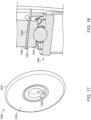
Fig. 17 is a perspective view of a press wheel according to certain embodiments. -
Fig. 18 is a cutaway view of a portion of the press wheel illustrated inFig. 17 . -
Fig. 19 is an exploded cutaway view of a press wheel according to certain embodiments. -
Fig. 20 is a cutaway view of a portion of the press wheel illustrated inFig. 19 . -
Fig. 21 is a perspective view of a press wheel according to certain embodiments. -
Fig. 22 is a cutaway view of a portion of the press wheel illustrated inFig. 21 . -
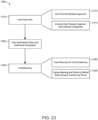
Fig. 23 is a schematic flow diagram of a process according to certain embodiments. - Although the concepts of the present disclosure are susceptible to various modifications and alternative forms, specific embodiments have been shown by way of example in the drawings and will be described herein in detail. It should be understood, however, that there is no intent to limit the concepts of the present disclosure to the particular forms disclosed, but on the contrary, the intention is to cover all modifications, equivalents, and alternatives consistent with the present disclosure and the appended claims.
- References in the specification to "one embodiment," "an embodiment," "an illustrative embodiment," etc., indicate that the embodiment described may include a particular feature, structure, or characteristic, but every embodiment may or may not necessarily include that particular feature, structure, or characteristic. Moreover, such phrases are not necessarily referring to the same embodiment. It should further be appreciated that although reference to a "preferred" component or feature may indicate the desirability of a particular component or feature with respect to an embodiment, the disclosure is not so limiting with respect to other embodiments, which may omit such a component or feature. Further, when a particular feature, structure, or characteristic is described in connection with an embodiment, it is submitted that it is within the knowledge of one skilled in the art to implement such feature, structure, or characteristic in connection with other embodiments whether or not explicitly described.
- Additionally, it should be appreciated that items included in a list in the form of "at least one of A, B, and C" can mean (A); (B); (C); (A and B); (B and C); (A and C); or (A, B, and C). Similarly, items listed in the form of "at least one of A, B, or C" can mean (A); (B); (C); (A and B); (B and C); (A and C); or (A, B, and C). Items listed in the form of "A, B, and/or C" can also mean (A); (B); (C); (A and B); (B and C); (A and C); or (A, B, and C). Further, with respect to the claims, the use of words and phrases such as "a," "an," "at least one," and/or "at least one portion" should not be interpreted so as to be limiting to only one such element unless specifically stated to the contrary, and the use of phrases such as "at least a portion" and/or "a portion" should be interpreted as encompassing both embodiments including only a portion of such element and embodiments including the entirety of such element unless specifically stated to the contrary.
- In the drawings, some structural or method features may be shown in certain specific arrangements and/or orderings. However, it should be appreciated that such specific arrangements and/or orderings may not necessarily be required. Rather, in some embodiments, such features may be arranged in a different manner and/or order than shown in the illustrative figures unless indicated to the contrary. Additionally, the inclusion of a structural or method feature in a particular figure is not meant to imply that such feature is required in all embodiments and, in some embodiments, may be omitted or may be combined with other features.
- With reference to
Fig. 1 , illustrated therein is mobile agricultural equipment in the form of aseeder 100 according to certain embodiments. Theseeder 100 generally includes aframe 110, one ormore reservoirs 120 operable to hold an agricultural product (e.g., seed), and a plurality ofrow units 130 mounted to theframe 110. As described herein, theseeder 100 is configured to form furrows 90 in the ground, eachfurrow 90 being provided with agricultural product from thereservoir 120 via therow units 130. - Each
row unit 130 includes one or more components to perform corresponding operations for the process of forming and seeding thefurrows 90. In the illustrated form, eachrow unit 130 generally includes anopening disk 132 that opens thefurrow 90, adistribution unit 134 that distributes seed into the openedfurrow 90, apress wheel 136 that presses the seed into thefurrow 90, and aclosing wheel 138 that covers the seed and closes thefurrow 90. - With additional reference to
Fig. 2 , illustrated therein is apress wheel assembly 200 according to certain embodiments. Thepress wheel assembly 200 may, for example, be provided in one or more of therow units 130 of the above-describedseeder 100. Thepress wheel assembly 200 generally includes aframe 210 and apress wheel 220 rotatably mounted to theframe 210. In the illustrated arrangement, thepress wheel assembly 200 is provided in a retracted configuration, in which thepress wheel 220 is retracted to a position adjacent theframe 210. From this configuration, thepress wheel assembly 200 may be moved to a deployed configuration, in which thepress wheel 220 is positioned generally below and/or behind theframe 210. - With additional reference to
Fig. 3 , illustrated therein is apress wheel 300 according to certain embodiments. Thepress wheel 300 may, for example, be utilized in thepress wheel assembly 200 and/or as thepress wheel 136 of the above-describedrow units 130. Thepress wheel 300 is rotatable about arotational axis 301, and generally includes anouter rim 310, aninner rim 320, and abody portion 330 extending between and connecting theouter rim 310 and theinner rim 320. In the illustrated form, thepress wheel 300 further includes abearing 340 that facilitates the rotational coupling of thewheel 300 to a frame (e.g., the frame 210). - In the illustrated embodiment, the
outer rim 310 and thewheel body 330 are integrally formed as a monolithic or single-piece construction. As described herein, it is also contemplated that theouter rim 310 may be one or more distinct components to which thewheel body 330 is attached. - With additional reference to
Fig. 4 , theinner rim 320 of the illustratedpress wheel 300 is generally annular, and has a serpentine configuration about its circumference. Theinner rim 320 has acentral opening 321, a firstaxial side 322 and an axially-oppositesecond side 324, and recesses in the form ofslots 326, 326' alternatingly extend from the twosides inner rim 320. More particularly,first slots 326 extend axially from the firstaxial side 322 toward the secondaxial side 324, andsecond slots 326 extend axially from the secondaxial side 324 toward the firstaxial side 322. As described herein, this serpentine configuration may serve one or more functions for thepress wheel 300, such as providing greater tolerances and/or reducing relative axial movement of theinner rim 320 andwheel body 330. In certain forms, theinner rim 320 may be formed of a metal material, such as steel. - The
wheel body 330 is somewhat flexible, and may, for example, be formed of an elastomeric material. In certain embodiments, thewheel body 330 is over-molded onto theouter rim 310 and/or theinner rim 320. Additionally or alternatively, thewheel body 330 may be connected to theouter rim 310 and/or theinner rim 320 via mechanical and/or chemical fasteners. As one example, a bonding agent may provide a chemical adhesion between thewheel body 330 and at theouter rim 310 and/or theinner rim 320. In certain embodiments, at least a portion of thewheel body 330 may be hollow. In certain embodiments, thewheel body 330 may be solid and substantially without hollow portions. - In certain embodiments, such as those in which the
wheel body 330 is over-molded onto theinner rim 320, thewheel body 330 may be provided withridges 336 corresponding to theslots 326 of theinner rim 320. Theseridges 336 engage theslots 326 and discourage relative axial shifting of theinner rim 320 andwheel body 330. Theslots 326 also render theinner rim 320 more flexible than a truly annular inner rim would be, which may provide for increased tolerances for pressfitting the bearing 340 into the central opening of theinner rim 320. - As noted above, in the illustrated form, the
outer rim 310 and thewheel body 330 are provided as a single-piece construction. In certain embodiments, this single-piece construction may, for example, be formed by injecting a liquid elastomeric composition into an appropriately-shaped mold. Moreover, the liquid composition may be mixed with a plastic powder that renders the resultingouter rim 310 and/orwheel body 330 less susceptible to having mud and other debris stick thereon. For example, at least some of the elastomeric composition may be mixed with ultra-high molecular weight polyethylene (UHMWPE) powder. In certain embodiments, the UHMWPE powder may be at least 5% of the total weight of the mixture, at least 10% of the total weight of the mixture, at least 20% of the total weight of the mixture, at least 30% of the total weight of the mixture, at least 40% of the total weight of the mixture, at least 50% of the total weight of the mixture, or at least 60% of the total weight of the mixture. Additionally, it is also contemplated that such a mixture may be utilized to form the wheel bodies of other embodiments described herein. - With additional reference to
Fig. 5 , illustrated therein is apress wheel 400 according to certain embodiments. Thepress wheel 400 may, for example, be utilized in thepress wheel assembly 200 and/or as thepress wheel 136 of the above-describedrow units 130. Thepress wheel 400 is substantially similar to thepress wheel 300 illustrated inFig. 3 and 4 , and similar reference characters are used to indicate similar elements and features. For example, thepress wheel 400 generally includes anouter rim 410, aninner rim 420, and abody portion 430, which respectively correspond to theouter rim 310, theinner rim 320, and thebody portion 330 of the above-describedpress wheel 300. In the interest of conciseness, the following description of thepress wheel 400 focuses primarily on elements and features that are different from those described above with reference to thepress wheel 300. - With additional reference to
Fig. 6 , theouter rim 410 is defined by at least one discrete component to which thewheel body 430 is attached, for example by over-molding. In certain embodiments, theouter rim 410 is formed of a material different from that utilized for thewheel body 430. In certain forms, theouter rim 410 may be formed of a material that is harder than the relatively softer material utilized for thewheel body 430. Theouter rim 410 may, for example, be provided with a Shore A hardness rating of between 40 and 70, such as a hardness of about 60 Shore A (e.g., between 55 Shore A and 65 Shore A). Theouter rim 410 may be formed of a plastic material, such as urethane, polyurethane, polyethylene, and/or ultra-high molecular weight polyethylene (UHMWPE). - The
outer rim 410 generally includes arim body 412 and a plurality offlanges 414 projecting radially inward from therim body 412. Therim body 412 is generally annular, and has a smooth and curvedouter surface 413. One or more of theflanges 414 may include an aperture oropening 415 into which material of thewheel body 430 may flow during the over-molding process to mechanically secure thewheel body 430 to theouter rim 410. In certain forms, thewheel body 430 may be formed of a mixture including an elastomeric material and UHMWPE powder as described above. - With additional reference to
Fig. 7 , illustrated therein is apress wheel 500 according to certain embodiments. Thepress wheel 500 may, for example, be utilized in thepress wheel assembly 200 and/or as thepress wheel 136 of the above-describedrow units 130. Thepress wheel 500 is substantially similar to thepress wheel 400 illustrated inFig. 5 , and similar reference characters are used to indicate similar elements and features. For example, thepress wheel 500 generally includes anouter rim 510, aninner rim 520, and abody portion 530, which respectively correspond to theouter rim 410, theinner rim 420, and thebody portion 430 of the above-describedpress wheel 400. In the interest of conciseness, the following description of thepress wheel 500 focuses primarily on elements and features that are different from those described above with reference to thepress wheel 400. - With additional reference to
Fig. 8 , theouter rim 510 generally includes arim body 512 and a plurality offlanges 514 projecting radially inward from therim body 512. In the illustrated form, theflanges 514 are generally T-shaped, which may aid in mechanically securing thewheel body 530 to theouter rim 510. - With additional reference to
Fig. 9 , illustrated therein is apress wheel 600 according to certain embodiments. Thepress wheel 600 may, for example, be utilized in thepress wheel assembly 200 and/or as thepress wheel 136 of the above-describedrow units 130. Thepress wheel 600 is substantially similar to thepress wheel 400 illustrated inFig. 6 , and similar reference characters are used to indicate similar elements and features. For example, thepress wheel 600 generally includes anouter rim 610, aninner rim 620, and abody portion 630, which respectively correspond to theouter rim 410, theinner rim 420, and thebody portion 430 of the above-describedpress wheel 400. In the interest of conciseness, the following description of thepress wheel 600 focuses primarily on elements and features that are different from those described above with reference to thepress wheel 400. - With additional reference to
Fig. 10 , theouter rim 610 generally includes arim body 612 and a plurality offlanges 614 projecting radially inward from therim body 612. In the illustrated form, each of theflanges 614 includes a pair ofapertures 615, which may aid in mechanically securing thewheel body 630 to theouter rim 610. For example, material may flow into theapertures 615 during the over-molding process to thereby form projections within thewheel body 630. - With additional reference to
Fig. 11 , illustrated therein is apress wheel 700 according to certain embodiments. Thepress wheel 700 may, for example, be utilized in thepress wheel assembly 200 and/or as thepress wheel 136 of the above-describedrow units 130. Thepress wheel 700 is substantially similar to thepress wheel 400 illustrated inFig. 5 , and similar reference characters are used to indicate similar elements and features. For example, thepress wheel 700 generally includes anouter rim 710, aninner rim 720, and abody portion 730, which respectively correspond to theouter rim 410, theinner rim 420, and thebody portion 430 of the above-describedpress wheel 400. In the interest of conciseness, the following description of thepress wheel 700 focuses primarily on elements and features that are different from those described above with reference to thepress wheel 400. - With additional reference to
Fig. 12 , theouter rim 710 generally includes arim body 712 and a plurality offlanges 714 projecting radially inward from therim body 712. Eachflange 714 includes a pair of axially-projectinglobes 716 that project to the axially-outer surface of thepress wheel 700 and partially define a face of thepress wheel 700. In addition to aiding the mechanical coupling of thewheel body 730 with theouter rim 710, theselobes 716 may discourage detritus (e.g., mud) from sticking to the sidewalls of thepress wheel 700. - With additional reference to
Fig. 13 , illustrated therein is anouter rim 800 according to certain embodiments. Theouter rim 800 includes arim body 802 and may, for example, be utilized in a press wheel along the lines described above. As one example, theouter rim 800 may be utilized in thepress wheel 400 illustrated inFig. 5 in place of theouter rim 410. As described herein, the illustratedouter rim 800 is formed of a plurality of discretemodular segments 810. - With additional reference to
Fig. 14 , illustrated therein is one of themodular segments 810 of which theouter rim 800 is formed. Themodular segment 810 includes arim body segment 812 and aflange 814 projecting inward from therim body segment 812. Theflange 814 includes one ormore recesses 815 that may aid in mechanically coupling thesegment 812 to a wheel body that is over-molded onto theouter rim 800, and in the illustrated form further includes atongue 816 and agroove 818 having a shape complementary to that of thetongue 816. - The
outer rim 800 may, for example, be assembled by arranging a plurality of themodular segments 810 such that thearcuate body segments 812 form a generally annular outer rim body while interlocking thetongue 816 of eachsegment 810 with thegroove 818 of anadjacent segment 810. Theouter rim 800, and optionally an inner rim along the lines of theinner rim 320, may then be over-molded with an elastomeric material to form the wheel body of a press wheel. - With additional reference to
Fig. 15 , illustrated therein is anouter rim 900 according to certain embodiments. Theouter rim 900 includes arim body 902 and may, for example, be utilized in a press wheel along the lines described above. As one example, theouter rim 900 may be utilized in thepress wheel 400 illustrated inFig. 5 in place of theouter rim 410. As described herein, the illustratedouter rim 900 is formed of a plurality of discretemodular segments 910. - With additional reference to
Fig. 16 , illustrated therein is one of themodular segments 910 of which theouter rim 900 is formed. Themodular segment 910 includes arim body segment 912 and aflange 914 projecting inward from therim body segment 912. Theflange 914 includes one ormore recesses 915 that may aid in mechanically coupling thesegment 912 to a wheel body that is over-molded onto theouter rim 900, and in the illustrated form further includes aneck 916 that extends to ahead 918 including a pair ofshoulders 919. - The
outer rim 900 may, for example, be assembled by arranging a plurality of themodular segments 910 such that thebody segments 912 form a generally annular outer rim body while interlocking theflange 914 of eachsegment 910 with theinner rim 320. For example, theneck 916 of eachsegment 910 may be inserted into acorresponding slot 326, 326' of theinner rim 320 such that theshoulders 919 restrict movement of thesegment 910 relative to theinner rim 320. Theouter rim 900 and theinner rim 320 may then be over-molded with an elastomeric material (which may include UHMWPE powder) to form at least a portion of a press wheel. After the over-molding process is complete such that the wheel body secures thesegments 910 in place, theheads 918 may be trimmed from the inner perimeter to provide space for insertion of a bearing. - With additional reference to
Figs. 17 and 18 , illustrated therein is apress wheel 1000 according to certain embodiments. Thepress wheel 1000 may, for example, be utilized in thepress wheel assembly 200 and/or as thepress wheel 136 of the above-describedrow units 130. Thepress wheel 1000 generally includes anouter rim 1010, aninner rim 1020, and awheel body 1030. In the illustrated form, theouter rim 1010 is integrally formed with thewheel body 1030. It is also contemplated that theouter rim 1010 may be formed as a separate component, and that thewheel body 1030 may be over-molded onto such a separate component. Theouter rim 1010 may, by way of example, be provided in any of the forms described above with reference toFigs. 5-16 . - In the illustrated form, the
inner rim 1020 is annular, and projects axially beyond the faces of thewheel body 1030, which may be over-molded onto theinner rim 1020. Abearing 1040 may then be inserted into thecentral opening 1021 of theinner rim 1020, and the edges of theinner rim 1020 may be deformed radially inward to capture theouter race 1042 of thebearing 1040 between twolips 1024. - With additional reference to
Figs. 19 and 20 , illustrated therein is apress wheel 1100 according to certain embodiments. Thepress wheel 1100 may, for example, be utilized in thepress wheel assembly 200 and/or as thepress wheel 136 of the above-describedrow units 130. Thepress wheel 1100 generally includes anouter rim 1110, aninner rim 1120, and awheel body 1130. In the illustrated form, theouter rim 1110 is integrally formed with thewheel body 1130. It is also contemplated that theouter rim 1110 may be formed as a separate component, and that thewheel body 1130 may be over-molded onto such a separate component. By way of example, theouter rim 1110 may be provided in any of the forms described above with reference toFigs. 5-16 . - In the illustrated form, the
inner rim 1120 comprises a pair of interlocked components. The interlocked components include afirst component 1121 and asecond component 1125, which interlock with one another via an interlock mechanism 1129. Thefirst component 1121 includes anannular projection 1122 that is received in anannular groove 1132 of thewheel body 1130 to discourage relative radial shifting of thefirst component 1121 and thewheel body 1130. Similarly, thesecond component 1125 may include anannular projection 1126 that is received in anannular groove 1136 of thewheel body 1130 to discourage relative radial shifting of thesecond component 1125 and thewheel body 1130. - The
first component 1121 includes afemale boss 1123, and thesecond component 1125 includes amale boss 1127 sized and shaped to be received in thefemale boss 1123. The outer side of thefemale boss 1123 generally conforms to the inner periphery of thewheel body 1130, and the inner side of themale boss 1127 generally conforms to the outer periphery of abearing 1140. The inner side of thefemale boss 1123 includes one or more first engagement features 1124 of the interlock mechanism 1129, and the outer side of themale boss 1127 includes one or more second engagement features 1128 of the interlock mechanism 1129. - The interlock mechanism 1129 is configured to at least selectively interlock the
first component 1121 with thesecond component 1125 to thereby capture thebearing 1140 within theinner rim 1120. In the illustrated form, the engagement features 1124, 1128 are configured to snap into engagement with one another as themale boss 1127 is inserted into thefemale boss 1123. It is also contemplated that the interlock mechanism 1129 may be configured to interlock thecomponents male boss 1127 may screw into thefemale boss 1123. In certain forms, one or more of the engagement features on each side of the interlock mechanism 1129 may include gaps 1124' which, when aligned, reduce the force required to axially separate the twocomponents components - With additional reference to
Figs. 21 and 22 , illustrated therein is apress wheel 1200 according to certain embodiments. Thepress wheel 1200 may, for example, be utilized in thepress wheel assembly 200 and/or as thepress wheel 136 of the above-describedrow units 130. While not specifically illustrated inFig. 21 , it should be appreciated that theouter rim 1210 of thepress wheel 1200 may be provided along the lines of the outer rims described with reference toFigs. 5-16 , or may be integrally formed with thewheel body 1230. - The
press wheel 1200 generally includes awheel body 1230 and abearing 1240 seated in acentral opening 1231 of thewheel body 1230. Thewheel body 1230 is provided with (e.g., integrally formed with) a plurality oflips 1234, each of which projects beyond the outer periphery of thecentral opening 1231 to partially enclose thecentral opening 1231. Thebearing 1240 may be inserted into thecentral opening 1231 such that thelips 1234 axially retain thebearing 1240 within theopening 1231. - With additional reference to
Fig. 23 , illustrated therein is anexemplary process 1300 that may be performed to produce a press wheel. Blocks illustrated for the processes in the present application are understood to be examples only, and blocks may be combined or divided, and added or removed, as well as re-ordered in whole or in part, unless explicitly stated to the contrary. Additionally, while the blocks are illustrated in a relatively serial fashion, it is to be understood that two or more of the blocks may be performed concurrently or in parallel with one another. Theprocess 1300 may begin withblock 1310, which generally involves forming an outer rim of a press wheel. The outer rim may, for example, be formed of a plastic material, such as UHMWPE or a material comprising UHMWPE. In certain embodiments,block 1310 may involve forming the outer rim as a single-piece construction, for example by molding the outer rim. It is also contemplated thatblock 1310 may involve forming the outer rim from a plurality of modular segments. - By way of example, block 1310 may include
block 1312, which generally involves forming a plurality of discrete modular segments. In certain embodiments,block 1312 may involve forming each modular segment with a rim body segment and a flange projecting inward from the rim body segment.Block 1310 may further involveblock 1314, which generally involves interlocking each modular segment with another component to form the outer rim. - In certain embodiments, the component with which the modular segment is interlocked in
block 1314 may be another modular component. For example, when forming theouter rim 800 of themodular segments 810, eachmodular segment 810 may be interlocked with adjacent modular segments via engagement of thetongues 816 andgrooves 818. Additionally or alternatively, the component with which the modular segment is interlocked may be an inner rim. For example, when forming theouter rim 900 of themodular segments 910, theheads 918 may be positioned in thecentral opening 321 of theinner rim 320 such that theneck 916 extends through one of theslots 326, 326'. - The
process 1300 may includeblock 1320, which generally involves over-molding a wheel body onto at least one additional component. In certain embodiments, the at least one additional component comprises an outer rim, such as the outer rim formed inblock 1320. Additionally or alternatively, the at least one additional component may comprise an inner rim, such as theinner rim 320 illustrated inFig. 4 . In certain forms, the inner rim includes a plurality of recesses (e.g.,slots 326, 326') such that the over-molding process results in one ormore ridges 336 received in and engaged with the recesses. - In certain embodiments, the outer rim onto which the wheel body is over-molded may include a rim body and a plurality of flanges projecting inward from the rim body. In some such forms, one or more of the flanges may include openings (e.g., the
openings 415 in theouter rim 410 illustrated inFig. 6 ) such that the over-molding forms the wheel body with one or more projections that extend into the openings. In certain forms, one or more of the flanges may extend axially and partially define a face of the press wheel, for example as illustrated inFigs. 11 and 12 . - The
process 1300 may includeblock 1330, which generally involves installing a bearing to the press wheel. For example, block 1330 may includeblock 1332, which generally involves inserting the bearing into a central aperture of the wheel body.Block 1330 may also includeblock 1334, which generally involves capturing a radially outer portion of the bearing and a radially inner portion of the wheel body between a pair of interlocking pieces, thereby coupling the bearing with the wheel body. For example, block 1334 may involve capturing the outer race of thebearing 1140 and a portion of thewheel body 1130 between the interlockingcomponents inner rim 1120 illustrated inFigs. 19 and 20 . - While the invention has been illustrated and described in detail in the drawings and foregoing description, the same is to be considered as illustrative and not restrictive in character, it being understood that only the preferred embodiments have been shown and described and that all changes and modifications that come within the spirit of the inventions are desired to be protected. It should be understood that while the use of words such as preferable, preferably, preferred or more preferred utilized in the description above indicate that the feature so described may be more desirable, it nonetheless may not be necessary and embodiments lacking the same may be contemplated as within the scope of the invention, the scope being defined by the claims that follow. In reading the claims, it is intended that when words such as "a," "an," "at least one," or "at least one portion" are used there is no intention to limit the claim to only one item unless specifically stated to the contrary in the claim. When the language "at least a portion" and/or "a portion" is used the item can include a portion and/or the entire item unless specifically stated to the contrary.
Claims (15)
- A press wheel (300) for agricultural equipment (100), the press wheel (300) comprising:an annular inner rim (320) extending along a rotational axis (301) and defining a central opening (321); anda wheel body (330) circumferentially surrounding the inner rim (320);wherein the inner rim (320) comprises a plurality of axially-extending recesses (326, 326').
- The press wheel (300) of claim 1, wherein the inner rim (320) has a first side (322) and a second side (324) opposite the first side (322);wherein the plurality of axially-extending recesses (326, 326') comprises a plurality of first axially-extending recesses (326) and a plurality of second axially-extending recesses (326');wherein each of the first axially-extending recesses (326) extends from the first side (322) toward the second side (324); andwherein each of the second axially-extending recesses (326') extends from the second side (324) toward the first side (322).
- The press wheel (300) of claim 2, wherein the first axially-extending recesses (326) and the second axially-extending recesses (326') alternate about a circumference of the inner rim (320).
- The press wheel (300) of one of the claims 1 to 3, wherein the inner rim (320) comprises a serpentine shape defined at least in part by the plurality of axially-extending recesses (326, 326'); or
wherein the wheel body (330) comprises a plurality of ridges (336) received in and engaged with the plurality of axially-extending recesses (326, 326'). - The press wheel (300) of one of the claims 1 to 4, wherein the inner rim (320) is chemically bonded to the wheel body (330); or
wherein each of the axially-extending recesses (326, 326') is an axially-extending slot (326, 326'). - The press wheel (300) of one of the claims 1 to 5, further comprising a bearing (340) positioned in the central opening (321) and forming a press fit with the inner rim (320).
- The press wheel (300) of one of the claims 1 to 6, further comprising an outer rim (310) circumferentially surrounding the wheel body (330);
wherein the outer rim (310) comprises urethane and/or ultra-high molecular weight polyethylene. - A method (1300) of manufacturing a press wheel for agricultural equipment according to one of the claims 1 to 7, the method (1300) comprising:over-molding (1320) a wheel body (330, 430, 530, 630, 730) onto at least one additional component, wherein the at least one additional component comprises an outer rim (310, 410, 510, 610, 710, 800, 900, 1010, 1110, 1210);wherein outer rim (310, 410, 510, 610, 710, 800, 900, 1010, 1110, 1210) is formed of a plastic material; andwherein the wheel body (330, 430, 530, 630, 730) is formed of an elastomeric material.
- The method (1300) of claim 8, wherein the plastic material comprises urethane and/or ultra-high molecular weight polyethylene.
- The method (1300) of claim 8 or 9, wherein the at least one additional component further comprises an inner rim (320);wherein the inner rim (320) comprises a plurality of recesses (326, 326'); andwherein the over-molding (1320) forms the wheel body (330, 430, 530, 630, 730) with a plurality of ridges (336) received in and engaged with the plurality of recesses (326, 326').
- The method (1300) of one of the claims 8 to 10, wherein the outer rim (410, 510, 610, 710, 800, 900) comprises:a rim body (412, 512, 612, 712, 802, 902); anda plurality of flanges (414, 514, 614, 714, 814, 914) projecting inward from the rim body (412, 512, 612, 712, 802, 902).
- The method (1300) of one of the claims 8 to 11, wherein one or more of the flanges (414, 614) comprises one or more openings (415, 615) such that the over-molding forms the wheel body (330, 430, 530, 630, 730) with one or more projections received in the one or more openings (415, 615); or
wherein one or more of the flanges (714) extends axially, and partially defines a face of the press wheel. - The method (1300) of one of the claims 8 to 12, further comprising, prior to over-molding (1320) the wheel body onto the at least one additional component, forming (1310) the outer rim (800, 900) of a plurality of modular segments (810, 910).
- The method (1300) of one of the claims 8 to 13, wherein forming (1310) the outer rim (800) comprises interlocking one or more of the modular segments (810) with an adjacent one of the modular segments (810).
- The method (1300) of one of the claims 8 to 14, wherein the at least one additional component comprises the inner rim (320); and wherein forming the outer rim (900) comprises interlocking one or more of the modular segments (910) with the inner rim (320).
Applications Claiming Priority (1)
| Application Number | Priority Date | Filing Date | Title |
|---|---|---|---|
| US17/837,539 US20230397523A1 (en) | 2022-06-10 | 2022-06-10 | Press wheel |
Publications (2)
| Publication Number | Publication Date |
|---|---|
| EP4289245A1 true EP4289245A1 (en) | 2023-12-13 |
| EP4289245B1 EP4289245B1 (en) | 2025-08-06 |
Family
ID=86732355
Family Applications (1)
| Application Number | Title | Priority Date | Filing Date |
|---|---|---|---|
| EP23178083.4A Active EP4289245B1 (en) | 2022-06-10 | 2023-06-07 | Press wheel and method of manufacturing such |
Country Status (5)
| Country | Link |
|---|---|
| US (1) | US20230397523A1 (en) |
| EP (1) | EP4289245B1 (en) |
| AU (1) | AU2023202134A1 (en) |
| BR (1) | BR102023004263A2 (en) |
| CA (1) | CA3199190A1 (en) |
Cited By (1)
| Publication number | Priority date | Publication date | Assignee | Title |
|---|---|---|---|---|
| US20230232730A1 (en) * | 2018-05-15 | 2023-07-27 | Jeffrey L. Steinke | Gauge Arm |
Families Citing this family (1)
| Publication number | Priority date | Publication date | Assignee | Title |
|---|---|---|---|---|
| US11970031B2 (en) | 2019-02-13 | 2024-04-30 | Gallagher Corporation | Polyurethane gauge wheel tire |
Citations (3)
| Publication number | Priority date | Publication date | Assignee | Title |
|---|---|---|---|---|
| US5611292A (en) * | 1995-07-17 | 1997-03-18 | Great Plains Manufacturing, Incorporated | Seed firming wheel assembly with bearing cap |
| US6295939B1 (en) * | 1998-04-06 | 2001-10-02 | Ronald Emin Arthur Emms | Seed planter press-wheel assembly |
| EP2236317A1 (en) * | 2009-04-02 | 2010-10-06 | F.I.R. S.r.L. | A wheel, in particular for mobile apparatus such as carriages or the like, and a method for realising the wheel |
Family Cites Families (18)
| Publication number | Priority date | Publication date | Assignee | Title |
|---|---|---|---|---|
| US286183A (en) * | 1883-10-09 | Car-wheel | ||
| US2687682A (en) * | 1951-04-05 | 1954-08-31 | Deere & Co | Press wheel for planters |
| US3870371A (en) * | 1972-10-25 | 1975-03-11 | Circle Eng Co Inc | Driven plastic small vehicle wheel |
| US4153303A (en) * | 1978-02-10 | 1979-05-08 | Arundale, Inc. | Multipart hub assembly |
| US4634189A (en) * | 1982-06-28 | 1987-01-06 | Hamelin Industries, Inc. | Wheel hub including structure for attachment of accessories |
| US5794713A (en) * | 1996-08-15 | 1998-08-18 | Ron Lefevre | Universal hub assembly |
| US5970891A (en) * | 1997-06-05 | 1999-10-26 | Schlagel Manufacturing, Inc. | Seed planter with gauge wheels and closing wheels having horizontal fingers |
| US20080179940A1 (en) * | 2004-05-18 | 2008-07-31 | Giles A. Hill | Solid rubber tire with flexible hub and replaceable tire tread |
| US7878600B2 (en) * | 2007-06-05 | 2011-02-01 | Stellana U.S. Inc. | Mechanical fastener for polyurethane wheels |
| US20100107946A1 (en) * | 2008-10-31 | 2010-05-06 | Kyle David Cooney | Wheel Hub And Bearing Assembly For Use In Agricultural Material Delivery Equipment |
| ES2559603T3 (en) * | 2011-09-22 | 2016-02-15 | Gatekeeper Systems, Inc. | Treadmills and replacement procedures for non-motorized vehicle wheels |
| FR3017267B1 (en) * | 2014-02-10 | 2016-10-07 | Otico | WHEEL FORMING ENHANCED AGRICULTURAL TOOL |
| DE102015118640A1 (en) * | 2015-10-30 | 2017-05-04 | Lemken Gmbh & Co. Kg | Pinch roller for an agricultural seeder |
| FR3052327B1 (en) * | 2016-06-14 | 2018-06-29 | Otico | AGRICULTURAL ROLLER |
| IT201700061686A1 (en) * | 2017-06-06 | 2018-12-06 | Maschio Gaspardo Spa | Wheel of seed awards |
| CA3131355C (en) * | 2019-05-03 | 2025-05-06 | Precision Planting Llc | Wheel for closing system |
| US11904631B2 (en) * | 2020-08-21 | 2024-02-20 | Michael Remo | Segmented wheels |
| US20230225240A1 (en) * | 2022-01-14 | 2023-07-20 | Schaffert Manufacturing Company, Inc. | Modular wheel assembly |
-
2022
- 2022-06-10 US US17/837,539 patent/US20230397523A1/en active Pending
-
2023
- 2023-03-07 BR BR102023004263-5A patent/BR102023004263A2/en unknown
- 2023-04-06 AU AU2023202134A patent/AU2023202134A1/en active Pending
- 2023-05-10 CA CA3199190A patent/CA3199190A1/en active Pending
- 2023-06-07 EP EP23178083.4A patent/EP4289245B1/en active Active
Patent Citations (3)
| Publication number | Priority date | Publication date | Assignee | Title |
|---|---|---|---|---|
| US5611292A (en) * | 1995-07-17 | 1997-03-18 | Great Plains Manufacturing, Incorporated | Seed firming wheel assembly with bearing cap |
| US6295939B1 (en) * | 1998-04-06 | 2001-10-02 | Ronald Emin Arthur Emms | Seed planter press-wheel assembly |
| EP2236317A1 (en) * | 2009-04-02 | 2010-10-06 | F.I.R. S.r.L. | A wheel, in particular for mobile apparatus such as carriages or the like, and a method for realising the wheel |
Cited By (1)
| Publication number | Priority date | Publication date | Assignee | Title |
|---|---|---|---|---|
| US20230232730A1 (en) * | 2018-05-15 | 2023-07-27 | Jeffrey L. Steinke | Gauge Arm |
Also Published As
| Publication number | Publication date |
|---|---|
| CA3199190A1 (en) | 2023-12-10 |
| BR102023004263A2 (en) | 2023-12-19 |
| AU2023202134A1 (en) | 2024-01-04 |
| EP4289245B1 (en) | 2025-08-06 |
| US20230397523A1 (en) | 2023-12-14 |
Similar Documents
| Publication | Publication Date | Title |
|---|---|---|
| EP4289245A1 (en) | Press wheel and method of manufacturing such | |
| US8567463B2 (en) | Semi-hollow pneumatic tire and associated wheel rim, notably for agricultural machinery | |
| US9439478B2 (en) | Removable outsole elements for articles of footwear | |
| US8667714B2 (en) | Attachment and locking system for replaceable traction cleats | |
| US6397499B1 (en) | Quick release cleat system | |
| US6108944A (en) | Quick-release connector | |
| US8191286B2 (en) | Traction cleat system for an athletic shoe | |
| CA2852207C (en) | Cleat for footwear | |
| US9151388B2 (en) | Sealing gasket and seed housing for a seeder and seeder comprising such a seed housing | |
| AU2011202961B2 (en) | A manifold and distribution manifold assembly for air-entrained material | |
| EP2399443B1 (en) | Distribution manifold assembly for an agricultural seeder | |
| US7076894B2 (en) | Reversible cleat system | |
| US20250100329A1 (en) | Polyurethane gauge wheel tire | |
| US6874941B2 (en) | Wheel hub-and-bearing set assembly for a roller skate | |
| JPH0650359A (en) | Cage for unidirectional clutch and sprag combination structure | |
| US8714278B2 (en) | Soil treatment apparatus, a soil treatment component and a method of assembling a soil treatment apparatus | |
| US12291291B2 (en) | Segmented wheel | |
| US5765928A (en) | Method of constructing a reusable in-line skate wheel | |
| US20250160242A1 (en) | Closing wheel with rim | |
| JP5858383B2 (en) | Doyo ring | |
| AU2017351739B2 (en) | A press wheel for a seeding machine | |
| KR101700614B1 (en) | Disc rotary blade for no tillage | |
| JP2003211903A (en) | Agricultural wheels |
Legal Events
| Date | Code | Title | Description |
|---|---|---|---|
| PUAI | Public reference made under article 153(3) epc to a published international application that has entered the european phase |
Free format text: ORIGINAL CODE: 0009012 |
|
| STAA | Information on the status of an ep patent application or granted ep patent |
Free format text: STATUS: THE APPLICATION HAS BEEN PUBLISHED |
|
| AK | Designated contracting states |
Kind code of ref document: A1 Designated state(s): AL AT BE BG CH CY CZ DE DK EE ES FI FR GB GR HR HU IE IS IT LI LT LU LV MC ME MK MT NL NO PL PT RO RS SE SI SK SM TR |
|
| STAA | Information on the status of an ep patent application or granted ep patent |
Free format text: STATUS: REQUEST FOR EXAMINATION WAS MADE |
|
| 17P | Request for examination filed |
Effective date: 20240613 |
|
| RBV | Designated contracting states (corrected) |
Designated state(s): AL AT BE BG CH CY CZ DE DK EE ES FI FR GB GR HR HU IE IS IT LI LT LU LV MC ME MK MT NL NO PL PT RO RS SE SI SK SM TR |
|
| GRAP | Despatch of communication of intention to grant a patent |
Free format text: ORIGINAL CODE: EPIDOSNIGR1 |
|
| STAA | Information on the status of an ep patent application or granted ep patent |
Free format text: STATUS: GRANT OF PATENT IS INTENDED |
|
| RIC1 | Information provided on ipc code assigned before grant |
Ipc: A01C 5/06 20060101AFI20250328BHEP |
|
| INTG | Intention to grant announced |
Effective date: 20250409 |
|
| GRAS | Grant fee paid |
Free format text: ORIGINAL CODE: EPIDOSNIGR3 |
|
| GRAA | (expected) grant |
Free format text: ORIGINAL CODE: 0009210 |
|
| STAA | Information on the status of an ep patent application or granted ep patent |
Free format text: STATUS: THE PATENT HAS BEEN GRANTED |
|
| AK | Designated contracting states |
Kind code of ref document: B1 Designated state(s): AL AT BE BG CH CY CZ DE DK EE ES FI FR GB GR HR HU IE IS IT LI LT LU LV MC ME MK MT NL NO PL PT RO RS SE SI SK SM TR |
|
| REG | Reference to a national code |
Ref country code: GB Ref legal event code: FG4D |
|
| REG | Reference to a national code |
Ref country code: CH Ref legal event code: EP |
|
| REG | Reference to a national code |
Ref country code: DE Ref legal event code: R096 Ref document number: 602023005370 Country of ref document: DE |
|
| REG | Reference to a national code |
Ref country code: IE Ref legal event code: FG4D |
|
| REG | Reference to a national code |
Ref country code: NL Ref legal event code: MP Effective date: 20250806 |
|
| PG25 | Lapsed in a contracting state [announced via postgrant information from national office to epo] |
Ref country code: IS Free format text: LAPSE BECAUSE OF FAILURE TO SUBMIT A TRANSLATION OF THE DESCRIPTION OR TO PAY THE FEE WITHIN THE PRESCRIBED TIME-LIMIT Effective date: 20251206 |
|
| PG25 | Lapsed in a contracting state [announced via postgrant information from national office to epo] |
Ref country code: NO Free format text: LAPSE BECAUSE OF FAILURE TO SUBMIT A TRANSLATION OF THE DESCRIPTION OR TO PAY THE FEE WITHIN THE PRESCRIBED TIME-LIMIT Effective date: 20251106 |
|
| REG | Reference to a national code |
Ref country code: LT Ref legal event code: MG9D |
|
| PG25 | Lapsed in a contracting state [announced via postgrant information from national office to epo] |
Ref country code: PT Free format text: LAPSE BECAUSE OF FAILURE TO SUBMIT A TRANSLATION OF THE DESCRIPTION OR TO PAY THE FEE WITHIN THE PRESCRIBED TIME-LIMIT Effective date: 20251209 |
|
| PG25 | Lapsed in a contracting state [announced via postgrant information from national office to epo] |
Ref country code: FI Free format text: LAPSE BECAUSE OF FAILURE TO SUBMIT A TRANSLATION OF THE DESCRIPTION OR TO PAY THE FEE WITHIN THE PRESCRIBED TIME-LIMIT Effective date: 20250806 |
|
| PG25 | Lapsed in a contracting state [announced via postgrant information from national office to epo] |
Ref country code: NL Free format text: LAPSE BECAUSE OF FAILURE TO SUBMIT A TRANSLATION OF THE DESCRIPTION OR TO PAY THE FEE WITHIN THE PRESCRIBED TIME-LIMIT Effective date: 20250806 Ref country code: HR Free format text: LAPSE BECAUSE OF FAILURE TO SUBMIT A TRANSLATION OF THE DESCRIPTION OR TO PAY THE FEE WITHIN THE PRESCRIBED TIME-LIMIT Effective date: 20250806 |
|
| PG25 | Lapsed in a contracting state [announced via postgrant information from national office to epo] |
Ref country code: GR Free format text: LAPSE BECAUSE OF FAILURE TO SUBMIT A TRANSLATION OF THE DESCRIPTION OR TO PAY THE FEE WITHIN THE PRESCRIBED TIME-LIMIT Effective date: 20251107 |
|
| PG25 | Lapsed in a contracting state [announced via postgrant information from national office to epo] |
Ref country code: SE Free format text: LAPSE BECAUSE OF FAILURE TO SUBMIT A TRANSLATION OF THE DESCRIPTION OR TO PAY THE FEE WITHIN THE PRESCRIBED TIME-LIMIT Effective date: 20250806 |
|
| PG25 | Lapsed in a contracting state [announced via postgrant information from national office to epo] |
Ref country code: LV Free format text: LAPSE BECAUSE OF FAILURE TO SUBMIT A TRANSLATION OF THE DESCRIPTION OR TO PAY THE FEE WITHIN THE PRESCRIBED TIME-LIMIT Effective date: 20250806 |
|
| PG25 | Lapsed in a contracting state [announced via postgrant information from national office to epo] |
Ref country code: PL Free format text: LAPSE BECAUSE OF FAILURE TO SUBMIT A TRANSLATION OF THE DESCRIPTION OR TO PAY THE FEE WITHIN THE PRESCRIBED TIME-LIMIT Effective date: 20250806 Ref country code: BG Free format text: LAPSE BECAUSE OF FAILURE TO SUBMIT A TRANSLATION OF THE DESCRIPTION OR TO PAY THE FEE WITHIN THE PRESCRIBED TIME-LIMIT Effective date: 20250806 |
|
| PG25 | Lapsed in a contracting state [announced via postgrant information from national office to epo] |
Ref country code: RS Free format text: LAPSE BECAUSE OF FAILURE TO SUBMIT A TRANSLATION OF THE DESCRIPTION OR TO PAY THE FEE WITHIN THE PRESCRIBED TIME-LIMIT Effective date: 20251106 |
|
| PG25 | Lapsed in a contracting state [announced via postgrant information from national office to epo] |
Ref country code: ES Free format text: LAPSE BECAUSE OF FAILURE TO SUBMIT A TRANSLATION OF THE DESCRIPTION OR TO PAY THE FEE WITHIN THE PRESCRIBED TIME-LIMIT Effective date: 20250806 |
|
| REG | Reference to a national code |
Ref country code: AT Ref legal event code: MK05 Ref document number: 1820622 Country of ref document: AT Kind code of ref document: T Effective date: 20250806 |
|
| PG25 | Lapsed in a contracting state [announced via postgrant information from national office to epo] |
Ref country code: SM Free format text: LAPSE BECAUSE OF FAILURE TO SUBMIT A TRANSLATION OF THE DESCRIPTION OR TO PAY THE FEE WITHIN THE PRESCRIBED TIME-LIMIT Effective date: 20250806 |
|
| PG25 | Lapsed in a contracting state [announced via postgrant information from national office to epo] |
Ref country code: DK Free format text: LAPSE BECAUSE OF FAILURE TO SUBMIT A TRANSLATION OF THE DESCRIPTION OR TO PAY THE FEE WITHIN THE PRESCRIBED TIME-LIMIT Effective date: 20250806 |
|
| PG25 | Lapsed in a contracting state [announced via postgrant information from national office to epo] |
Ref country code: AT Free format text: LAPSE BECAUSE OF FAILURE TO SUBMIT A TRANSLATION OF THE DESCRIPTION OR TO PAY THE FEE WITHIN THE PRESCRIBED TIME-LIMIT Effective date: 20250806 |
|
| PG25 | Lapsed in a contracting state [announced via postgrant information from national office to epo] |
Ref country code: IT Free format text: LAPSE BECAUSE OF FAILURE TO SUBMIT A TRANSLATION OF THE DESCRIPTION OR TO PAY THE FEE WITHIN THE PRESCRIBED TIME-LIMIT Effective date: 20250806 |
|
| PG25 | Lapsed in a contracting state [announced via postgrant information from national office to epo] |
Ref country code: CZ Free format text: LAPSE BECAUSE OF FAILURE TO SUBMIT A TRANSLATION OF THE DESCRIPTION OR TO PAY THE FEE WITHIN THE PRESCRIBED TIME-LIMIT Effective date: 20250806 |
|
| PG25 | Lapsed in a contracting state [announced via postgrant information from national office to epo] |
Ref country code: EE Free format text: LAPSE BECAUSE OF FAILURE TO SUBMIT A TRANSLATION OF THE DESCRIPTION OR TO PAY THE FEE WITHIN THE PRESCRIBED TIME-LIMIT Effective date: 20250806 Ref country code: SK Free format text: LAPSE BECAUSE OF FAILURE TO SUBMIT A TRANSLATION OF THE DESCRIPTION OR TO PAY THE FEE WITHIN THE PRESCRIBED TIME-LIMIT Effective date: 20250806 |