EP4288120B1 - Automated disinfection system for ct patient table - Google Patents
Automated disinfection system for ct patient table Download PDFInfo
- Publication number
- EP4288120B1 EP4288120B1 EP22706239.5A EP22706239A EP4288120B1 EP 4288120 B1 EP4288120 B1 EP 4288120B1 EP 22706239 A EP22706239 A EP 22706239A EP 4288120 B1 EP4288120 B1 EP 4288120B1
- Authority
- EP
- European Patent Office
- Prior art keywords
- disinfection
- patient table
- automated
- telescopic rod
- disinfection system
- Prior art date
- Legal status (The legal status is an assumption and is not a legal conclusion. Google has not performed a legal analysis and makes no representation as to the accuracy of the status listed.)
- Active
Links
Images



Classifications
-
- A—HUMAN NECESSITIES
- A61—MEDICAL OR VETERINARY SCIENCE; HYGIENE
- A61L—METHODS OR APPARATUS FOR STERILISING MATERIALS OR OBJECTS IN GENERAL; DISINFECTION, STERILISATION OR DEODORISATION OF AIR; CHEMICAL ASPECTS OF BANDAGES, DRESSINGS, ABSORBENT PADS OR SURGICAL ARTICLES; MATERIALS FOR BANDAGES, DRESSINGS, ABSORBENT PADS OR SURGICAL ARTICLES
- A61L2/00—Disinfection or sterilisation of materials or objects, in general; Accessories therefor
- A61L2/02—Disinfection or sterilisation of materials or objects, in general; Accessories therefor using physical processes
- A61L2/08—Radiation
- A61L2/10—Ultraviolet [UV] radiation
-
- A—HUMAN NECESSITIES
- A61—MEDICAL OR VETERINARY SCIENCE; HYGIENE
- A61L—METHODS OR APPARATUS FOR STERILISING MATERIALS OR OBJECTS IN GENERAL; DISINFECTION, STERILISATION OR DEODORISATION OF AIR; CHEMICAL ASPECTS OF BANDAGES, DRESSINGS, ABSORBENT PADS OR SURGICAL ARTICLES; MATERIALS FOR BANDAGES, DRESSINGS, ABSORBENT PADS OR SURGICAL ARTICLES
- A61L2/00—Disinfection or sterilisation of materials or objects, in general; Accessories therefor
- A61L2/24—Apparatus using programmed or automatic operation
-
- A—HUMAN NECESSITIES
- A61—MEDICAL OR VETERINARY SCIENCE; HYGIENE
- A61B—DIAGNOSIS; SURGERY; IDENTIFICATION
- A61B6/00—Apparatus or devices for radiation diagnosis; Apparatus or devices for radiation diagnosis combined with radiation therapy equipment
- A61B6/04—Positioning of patients; Tiltable beds or the like
- A61B6/0407—Supports, e.g. tables or beds, for the body or parts of the body
-
- A—HUMAN NECESSITIES
- A61—MEDICAL OR VETERINARY SCIENCE; HYGIENE
- A61L—METHODS OR APPARATUS FOR STERILISING MATERIALS OR OBJECTS IN GENERAL; DISINFECTION, STERILISATION OR DEODORISATION OF AIR; CHEMICAL ASPECTS OF BANDAGES, DRESSINGS, ABSORBENT PADS OR SURGICAL ARTICLES; MATERIALS FOR BANDAGES, DRESSINGS, ABSORBENT PADS OR SURGICAL ARTICLES
- A61L2103/00—Materials or objects being the target of disinfection or sterilisation
- A61L2103/15—Laboratory, medical or dentistry appliances, e.g. catheters or sharps
-
- A—HUMAN NECESSITIES
- A61—MEDICAL OR VETERINARY SCIENCE; HYGIENE
- A61L—METHODS OR APPARATUS FOR STERILISING MATERIALS OR OBJECTS IN GENERAL; DISINFECTION, STERILISATION OR DEODORISATION OF AIR; CHEMICAL ASPECTS OF BANDAGES, DRESSINGS, ABSORBENT PADS OR SURGICAL ARTICLES; MATERIALS FOR BANDAGES, DRESSINGS, ABSORBENT PADS OR SURGICAL ARTICLES
- A61L2202/00—Aspects relating to methods or apparatus for disinfecting or sterilising materials or objects
- A61L2202/10—Apparatus features
- A61L2202/11—Apparatus for generating biocidal substances, e.g. vaporisers, UV lamps
-
- A—HUMAN NECESSITIES
- A61—MEDICAL OR VETERINARY SCIENCE; HYGIENE
- A61L—METHODS OR APPARATUS FOR STERILISING MATERIALS OR OBJECTS IN GENERAL; DISINFECTION, STERILISATION OR DEODORISATION OF AIR; CHEMICAL ASPECTS OF BANDAGES, DRESSINGS, ABSORBENT PADS OR SURGICAL ARTICLES; MATERIALS FOR BANDAGES, DRESSINGS, ABSORBENT PADS OR SURGICAL ARTICLES
- A61L2202/00—Aspects relating to methods or apparatus for disinfecting or sterilising materials or objects
- A61L2202/10—Apparatus features
- A61L2202/14—Means for controlling sterilisation processes, data processing, presentation and storage means, e.g. sensors, controllers, programs
Definitions
- the invention relates to the field of CT devices, and in particular, to an automated disinfection system for a CT patient table.
- CT devices are often used to diagnose or treat patients.
- a patient enters a scanning room and lies on a CT patient table that can be moved automatically, which moves by a corresponding distance as required for scanning by X-ray.
- viruses may remain on the CT patient table after scanning, especially for the patient with epidemic respiratory infection.
- a use surface of the CT patient table or even ambient air in the scanning room needs to be disinfected after each patient is examined.
- air disinfection in the scanning room can be implemented in an automated manner by placing an ultraviolet disinfection lamp in the room and by means of air circulation.
- the device surface still needs to be disinfected by wiping disinfection reagents manually or irradiating with the ultraviolet disinfection lamp fixed in the scanning room for more than 30 minutes.
- the disinfection methods described above are time-consuming and cumbersome and pose a potential infection risk to the operator.
- CN 112 043 844 A shows a disinfection method for medical imaging equipment. Scanning information of a patient is judged through a scanning protocol of the medical imaging equipment, wherein the scanning information can be used for judging the contact position of the patient and the medical imaging equipment so that the disinfection intensity can be determined according to the type of the patient. The contact position of the patient and the medical imaging equipment is automatically disinfected according to the determined disinfection intensity by using a disinfection unit of the medical imaging equipment.
- US 2019/262487 A1 teaches a sterilization system which uses ultraviolet radiation and ozone to eradicate deadly pathogens to sterilize a zone of a surface of an object or wound/incision sites.
- the sterilization system offers a safe sterilization method prior to or after surgery and/or closure wounds/incisions.
- KR 101 724 481 B1 teaches a UV sterilizing system comprising: a UV sterilizing robot including a UV sterilizing device for emitting unidirectional UV light and capable of performing 3-degree-of-freedom movement, and a body for supporting the UV sterilizing device and being capable of autonomously moving and reading an unsterilized blind area, and configured to sterilize an object to be disinfected, and store several sorts of data related to a disinfection area.
- a UV sterilizing robot including a UV sterilizing device for emitting unidirectional UV light and capable of performing 3-degree-of-freedom movement, and a body for supporting the UV sterilizing device and being capable of autonomously moving and reading an unsterilized blind area, and configured to sterilize an object to be disinfected, and store several sorts of data related to a disinfection area.
- US 2017/112953 A1 teaches a decontamination apparatus and method involving a base, and a plurality of sources that each emit UVC light to render a target object pathogen reduced.
- a plurality of adjustable supports couple the sources to the base, and a controller is coupled to the base to be operatively connected to the sources to control emission of the UVC light.
- a disinfection system that can automatically, quickly and conveniently disinfect a surface of a CT patient table during scanning gaps of a plurality of patients is needed, and the disinfection system can merge a disinfection process into an existing workflow of a CT device.
- a main objective of the invention is to provide an automated disinfection system for a CT patient table, so as to solve a problem in the prior art that disinfection cannot be performed automatically and rapidly on a use surface of a CT patient table.
- an automated disinfection system for a CT patient table includes: a disinfection mechanism disposed above the CT patient table; a detection mechanism, disposed on the disinfection mechanism and disinfection system for a CT patient table includes: a disinfection mechanism disposed above the CT patient table; a detection mechanism, disposed on the disinfection mechanism and configured to detect a position of the CT patient table; and a control mechanism, configured to communicate with the disinfection mechanism by using a communication interface, so as to control start/stop and operation of the disinfection mechanism, where the disinfection mechanism is configured to perform horizontal movement and vertical movement during scanning gaps of a plurality of patients, so as to disinfect a use surface of the CT patient table.
- the automated disinfection system for a CT patient table is provided with the disinfection mechanism that can move horizontally and vertically and the detection mechanism, so that automatic and rapid disinfection on the CT patient table is implemented, and comprehensive disinfection of the CT patient table can be completed within scanning gaps of patients, without manual disinfection by an operator, thereby saving time and efforts.
- a remote operation can be controlled through the control mechanism that is communicatively connected to the disinfection mechanism, thereby avoiding a risk of cross-infection of the operator.
- the disinfection mechanism includes: a mounting member, installed on the ceiling and configured to move horizontally; a telescopic rod, where an upper end of the telescopic rod is fixedly connected to the mounting member, and the telescopic rod is configured to perform telescopic movement vertically; and a disinfection component, connected to a lower end of the telescopic rod and including a plurality of disinfection units, where the plurality of disinfection units are arranged to disinfect an upper surface and a side surface of the CT patient table.
- a specific structure form of the disinfection mechanism determines that the disinfection mechanism can effectively implement horizontal and vertical movement, and the structure form is simple.
- the mounting member includes a sliding element that can be slidably engaged in a track formed on the ceiling.
- the horizontal movement of the disinfection mechanism is realized by cooperating the sliding element with the track, which is easy to implement and easy to control.
- the disinfection component is pivotally connected to the telescopic rod by using a hinge, so that the disinfection component can rotate relative to the telescopic rod.
- a rotation setting manner of the disinfection component makes more flexible disinfection possible, so that a larger-range disinfection operation can be provided as required.
- the detection mechanism includes a first sensor and a plurality of second sensors positioned on the disinfection component, the first sensor is configured to sense a position of an end of the CT patient table in response to start of the disinfection mechanism, and when the position of the end of the CT patient table is sensed, the telescopic rod performs telescopic movement toward the CT patient table; and the second sensor is configured to sense a distance between the disinfection component and the CT patient table while the telescopic rod moves, when the distance between the disinfection component and the CT patient table is a first preset distance, the telescopic rod stops telescopic movement, and the disinfection mechanism moves horizontally by using the mounting member, so as to disinfect the upper surface and the side surface of the CT patient table.
- a horizontal position of the CT patient table can be accurately determined by using a sensing result of the first sensor, and after the horizontal position is determined, an optimal disinfection distance is determined by using a sensing result of the second sensor.
- the cooperation between the moving part and the sensor helps to realize the precise positioning of the disinfection mechanism relative to the CT patient table and smooth implementation of the disinfection task.
- the second sensor is further configured to sense an obstacle in the horizontal direction when the disinfection mechanism moves horizontally.
- the second sensor may further sense an obstacle in the horizontal direction, so that occurrence of a collision event is prevented when the disinfection mechanism moves horizontally in a disinfection process.
- the first preset distance is in a range of 195 mm-205 mm.
- the preset distance is an optimal distance for effective disinfection.
- the disinfection mechanism moves horizontally by a second preset distance, and the second preset distance is not less than a length of the CT patient table.
- the preset distance by which the disinfection mechanism moves horizontally is not less than the length of the CT patient table, so that the CT patient table can be completely disinfected.
- the first sensor is a distance sensor
- the plurality of second sensors are proximity sensors.
- the distance sensor and proximity sensors are common types of sensors that can effectively sense positions and distances.
- each of the plurality of disinfection units is an ultraviolet LED (UVC LED).
- An ultraviolet disinfection lamp replaces a traditional mercury lamp, and using the ultraviolet LED achieves benefits of energy saving, environmental protection, and compactness.
- an operating power and a moving speed of the disinfection mechanism are adjustable to achieve different disinfection rates.
- the automated disinfection system for a CT patient table further includes a start button and a stop button that are both disposed on a CT gantry.
- the start button and stop button can be set as an alternative for use in case of a system fault or emergency.
- the automated disinfection system for a CT patient table is further configured such that the disinfection component of the disinfection mechanism can rotate by a predetermined angle toward a CT gantry to disinfect the CT gantry.
- the automated disinfection system of the utility model may also be extended to disinfect a surface of the CT gantry.
- the automated disinfection system for a CT patient table is further configured such that the disinfection mechanism operates in a predetermined low power mode to disinfect ambient air.
- the automated disinfection system of the utility model may be further extended to disinfect ambient air in a scanning room.
- the disinfection mechanism that can move horizontally and vertically and the detection mechanism can be disposed, so that rapid and automated disinfection of the use surface of the CT patient table can be implemented during scanning gaps of a plurality of patients, thereby reducing a risk of cross-infection and saving manpower.
- the automated disinfection system for a CT patient table may be directly configured based on an existing CT device, and software and hardware of a current system need not be modified, thereby implementing convenient operation.
- the automated disinfection system for a CT patient table may further disinfect air in the scanning room and the surface of the CT gantry.
- an automated disinfection system for a CT patient table includes: a disinfection mechanism disposed above the CT patient table; a detection mechanism, disposed on the disinfection mechanism and configured to detect a position of the CT patient table; and a control mechanism, configured to communicate with the disinfection mechanism by using a communication interface, so as to control start/stop and operation of the disinfection mechanism, where the disinfection mechanism is configured to perform horizontal movement and vertical movement during scanning gaps of a plurality of patients, so as to disinfect a use surface of the CT patient table.
- FIG. 1 shows an automated disinfection system for a CT patient table according to an embodiment of the invention.
- the automated disinfection system includes a disinfection mechanism 1, a detection mechanism, and a control mechanism 3.
- the disinfection mechanism 1 is disposed above a CT patient table 10 and is configured to disinfect a use surface of the CT patient table during scanning gaps (for example, 2 minutes) of a plurality of patients.
- the use surface includes an upper surface in contact with a patient and a side surface that the patient's body may contact.
- the disinfection mechanism 1 may move horizontally and vertically when disinfecting the use surface of the CT patient table 10, where the disinfection mechanism may include a horizontal moving part 1a and a vertical moving part 1b.
- the detection mechanism is associated with the disinfection mechanism 1 and is used to detect a position of the CT patient table 10 relative to the disinfection mechanism 1.
- the detection mechanism may include a first sensor 21 and a second sensor 22, and a quantity of the first sensor and a quantity of the second sensor may be one or more. Details are described below.
- the control mechanism 3 may communicate with the disinfection mechanism 1 by using a communication interface 31, and is configured to control start/stop and operation of the disinfection mechanism 1. As a non-limiting example, the control mechanism 3 may be disposed at a remote position away from the disinfection mechanism 1, for example, a control room outside a scanning room, and integrated with a control system that controls a CT device.
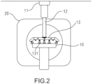
- FIG. 2 is a front view of a disinfection mechanism 1 configured to disinfect a use surface of a CT patient table according to an embodiment of the invention.
- the disinfection mechanism 1 includes a mounting member 11, a telescopic rod 12, and a disinfection component 13.
- the mounting member 11 is mounted on the ceiling of a scanning room, so that the disinfection mechanism 1 can be suspended downward from the ceiling.
- a sliding element may be disposed on the mounting member 11, and a track may be disposed on the ceiling, so that the sliding element is slidably engaged in the track, so that the disinfection mechanism 1 can move in horizontally relative to the CT patient table.
- a sliding element may be disposed on the mounting member 11, and a track may be disposed on the ceiling, so that the sliding element is slidably engaged in the track, so that the disinfection mechanism 1 can move in horizontally relative to the CT patient table.
- other structural forms that can realize horizontal movement of the disinfection mechanism 1 may also be used without exceeding the scope of the invention.
- the telescopic rod 12 is fixedly connected to the mounting member 11 at an upper end, and the telescopic rod may be configured to perform telescopic movement vertically relative to the mounting member 11.
- the telescopic rod 12 is connected to the disinfection component 13 at a lower end, so that the disinfection component can move vertically as the telescopic rod 12 moves.
- the disinfection component 13 may include a rotation part 1c, so that the disinfection component can rotate relative to the telescopic rod 12, for example, the disinfection component may be pivotally connected to the telescopic rod 12 by using a hinge.
- the disinfection component 13 may include a plurality of disinfection units 131.
- the disinfection units are distributed on a lower surface of the disinfection component in an array, and disinfect the use surface of the CT patient table.
- a distribution manner of the plurality of disinfection units 131 enables disinfection on both an upper surface and a side surface of the CT patient table.
- the plurality of disinfection units 131 use ultraviolet LEDs (UVC LED).
- UVC LED ultraviolet LEDs
- the disinfection unit may also use other forms that can effectively disinfect the use surface of the CT patient table.
- the structure of disinfection component 13 is variable.
- the disinfection component 13 may include a plurality of arms that are hinged and angularly disposed relative to each other.
- a first end arm and a second end arm at both ends of the disinfection component 13 may be disposed at an angle with respect to a first middle arm and a second middle arm at middle positions, so that the disinfection units 131 disposed at the first end arm and the second end arm can emit ultraviolet light toward the side surface of the CT patient table, and the disinfection units 131 disposed at the first middle arm and the second middle arm can emit ultraviolet light toward the upper surface of the CT patient table.
- the first middle arm and the second middle arm of the disinfection component 13 may be disposed at an angle relative to each other, the first middle arm and the first end arm may be disposed in a straight line, and the second middle arm and the second end arm are disposed in a straight line.
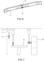
- a first sensor 21 and a second sensor 22 of the detection mechanism are described with reference to FIG. 4 to FIG. 6 .
- the first sensor 21 is disposed on a lower surface of the disinfection component 13, and when the disinfection mechanism is started to move horizontally, the first sensor may sense a position of an end of the CT patient table.
- the first sensor 21 is a distance sensor, and detection precision of the first sensor is +/-60 mm.
- a plurality of second sensors 22 are disposed on the disinfection component 13.
- One second sensor 22 is disposed on the lower surface of the disinfection component 13 and is positioned adjacent to the first sensor 21. As shown in FIG.
- the second sensor 22 may be configured to sense a distance between the disinfection component and the CT patient table when the disinfection component 13 moves downward toward the CT patient table by means of telescopic movement of the telescopic rod 12.
- the telescopic rod 12 stops telescopic movement.
- the first preset distance is in a range of 195 mm-205 mm, and more preferably, the first preset distance is 200 mm.
- several second sensors in the second sensors 22 may be disposed on two sides of the disinfection component 13, for example, each side has three second sensors.
- the second sensors 22 disposed on the sides of the disinfection component may be configured to sense an obstacle in the horizontal direction when the disinfection mechanism moves horizontally to disinfect the CT patient table, so as to prevent a collision. For example, when an obstacle is sensed at approximately 100 mm ahead, the disinfection mechanism 1 may stop moving horizontally. In addition, the disinfection mechanism 1 may move horizontally by a second preset distance at a specific speed (for example, 100 mm/s) along the CT patient table 10, where the second preset distance is not less than a length of the CT patient table, and for example, the second preset distance may be 2500 mm.
- the second sensor 22 is a proximity sensor.
- an operating power and a moving speed of the disinfection mechanism 1 are adjustable to achieve different disinfection rates.
- the disinfection unit 131 in the form of an ultraviolet LED of the disinfection mechanism 1 may operate in a low power mode, a medium power mode, or a high power mode.
- the automated disinfection system of the invention may further disinfect a CT gantry 20 and ambient air in a scanning room.
- the patient When a patient is scanned, the patient may contact a surface of the CT gantry 20. Therefore, it is necessary to disinfect the surface of the CT gantry in scanning gaps of a plurality of patients.
- the disinfection component 13 of the disinfection mechanism 1 When disinfection is performed on the surface of the CT gantry, the disinfection component 13 of the disinfection mechanism 1 may rotate by a predetermined angle (for example, 90 degrees) toward the surface of the CT gantry relative to the telescopic rod 12, so as to disinfect the surface.
- the disinfection mechanism 1 can only move horizontally without moving vertically to operate in the low power mode.
- the automated disinfection system may further include a start button 4 and a stop button 5 as an alternative or to be used manually by an operator in case of emergency. Both the start button 4 and the stop button 5 may be disposed on the CT gantry 20.
- the CT patient table 10 After scanning of a patient is complete, the CT patient table 10 returns to an initial position. An operator outside the scanning room may start the disinfection mechanism 1 by operating the control mechanism 3.
- the control mechanism may be integrated into a control system used for the CT device. For example, the operator may click a button such as "disinfect" displayed on a user interface of the control system to start a disinfection process. Then, the disinfection mechanism 1 moves horizontally by means of sliding of the mounting member 11 along the track on the ceiling, until the first sensor 21 senses a position of a first end of the CT patient table 10, and in this case, the disinfection mechanism 1 stops moving horizontally.
- the disinfection component 13 of the disinfection mechanism 1 moves downward toward the CT patient table 10 by using the telescopic rod 12, and the second sensor 22 senses a distance from the CT patient table.
- the telescopic rod 12 stops telescopic movement.
- an LED driver 14 used on the disinfection unit 131 of the disinfection component 13 activates the plurality of disinfection units 131 to start at a predetermined power, and the disinfection mechanism 1 moves horizontally again, so as to disinfect the use surface of the CT patient table 10 at a specific speed.
- the disinfection mechanism 1 returns when moving to a second end of the CT patient table 10.
- the disinfection unit 131 does not shut down, but continues to disinfect the use surface of the CT patient table.
- the disinfection mechanism 1 returns to the first end of the CT patient table, the disinfection unit 131 shuts down, and the disinfection mechanism 1 returns to the initial position by using the horizontal moving part and the vertical moving part. As such, disinfection is completed, so that a next patient can be scanned.
- the embodiments of the invention achieve several technical effects:
- the disinfection mechanism that can move horizontally and vertically and the detection mechanism can be disposed, so that rapid and automated disinfection of the use surface of the CT patient table can be implemented during scanning gaps of a plurality of patients, thereby reducing a risk of cross-infection and saving manpower.
- the automated disinfection system for a CT patient table may be directly configured based on an existing CT device, and software and hardware of a current system need not be modified, thereby implementing convenient operation.
- the automated disinfection system for a CT patient table may further disinfect air in the scanning room and the surface of the CT gantry.
- orientation or position relationships indicated by terms such as “front, back, upper, lower, left, right”, “horizontal, vertical”, and “top, bottom” are generally based on orientation or position relationships shown in the accompanying drawings, and are merely for ease of description of the utility model and simplified description. In a case in which no opposite description is provided, the orientation terms do not indicate and imply that the specified apparatus or component must have a specific orientation or must be constructed and operated at a specific orientation, and are not understood to limit the protection scope of the invention.
- orientation terms "inside and outside” refer to the inside and outside of the outline of each component.
- spatial relative terms such as “on ", “above ", “at an upper surface of ", “the above”, and the like are used to describe a spatial position relationship between a component or feature shown in the figure and another component or feature.
- the spatial relative term is intended to include different orientations in use or operation in addition to the orientations of the component described in the figure. For example, if the component in the drawing is inverted, the component described as “above other components or constructions” or “on other components or constructions” will be positioned as “below other components or constructions” or “under other components or constructions”.
- the exemplary term “above " may include “above " and “below ".
- the component may also be positioned in different manners (rotated by 90 degrees or in another orientation), and the spatial relative description used herein is explained accordingly.
Landscapes
- Health & Medical Sciences (AREA)
- Epidemiology (AREA)
- Life Sciences & Earth Sciences (AREA)
- Animal Behavior & Ethology (AREA)
- General Health & Medical Sciences (AREA)
- Public Health (AREA)
- Veterinary Medicine (AREA)
- Apparatus For Radiation Diagnosis (AREA)
Description
- The invention relates to the field of CT devices, and in particular, to an automated disinfection system for a CT patient table.
- In the medical field, CT devices are often used to diagnose or treat patients. During examination, a patient enters a scanning room and lies on a CT patient table that can be moved automatically, which moves by a corresponding distance as required for scanning by X-ray.
- During the above examination, because the patient is in direct contact with the CT patient table, viruses may remain on the CT patient table after scanning, especially for the patient with epidemic respiratory infection. To avoid cross-infection, a use surface of the CT patient table or even ambient air in the scanning room needs to be disinfected after each patient is examined.
- At present, air disinfection in the scanning room can be implemented in an automated manner by placing an ultraviolet disinfection lamp in the room and by means of air circulation. However, the device surface still needs to be disinfected by wiping disinfection reagents manually or irradiating with the ultraviolet disinfection lamp fixed in the scanning room for more than 30 minutes. The disinfection methods described above are time-consuming and cumbersome and pose a potential infection risk to the operator.
-
CN 112 043 844 A shows a disinfection method for medical imaging equipment. Scanning information of a patient is judged through a scanning protocol of the medical imaging equipment, wherein the scanning information can be used for judging the contact position of the patient and the medical imaging equipment so that the disinfection intensity can be determined according to the type of the patient. The contact position of the patient and the medical imaging equipment is automatically disinfected according to the determined disinfection intensity by using a disinfection unit of the medical imaging equipment. -
US 2019/262487 A1 teaches a sterilization system which uses ultraviolet radiation and ozone to eradicate deadly pathogens to sterilize a zone of a surface of an object or wound/incision sites. The sterilization system offers a safe sterilization method prior to or after surgery and/or closure wounds/incisions. -
KR 101 724 481 B1 -
US 2017/112953 A1 teaches a decontamination apparatus and method involving a base, and a plurality of sources that each emit UVC light to render a target object pathogen reduced. A plurality of adjustable supports couple the sources to the base, and a controller is coupled to the base to be operatively connected to the sources to control emission of the UVC light. - Therefore, to solve the foregoing problems, a disinfection system that can automatically, quickly and conveniently disinfect a surface of a CT patient table during scanning gaps of a plurality of patients is needed, and the disinfection system can merge a disinfection process into an existing workflow of a CT device.
- A main objective of the invention is to provide an automated disinfection system for a CT patient table, so as to solve a problem in the prior art that disinfection cannot be performed automatically and rapidly on a use surface of a CT patient table.
- To achieve the foregoing objective, according to an aspect of the invention, an automated disinfection system for a CT patient table is provided, where the automated disinfection system for a CT patient table includes: a disinfection mechanism disposed above the CT patient table; a detection mechanism, disposed on the disinfection mechanism and disinfection system for a CT patient table includes: a disinfection mechanism disposed above the CT patient table; a detection mechanism, disposed on the disinfection mechanism and configured to detect a position of the CT patient table; and a control mechanism, configured to communicate with the disinfection mechanism by using a communication interface, so as to control start/stop and operation of the disinfection mechanism, where the disinfection mechanism is configured to perform horizontal movement and vertical movement during scanning gaps of a plurality of patients, so as to disinfect a use surface of the CT patient table.
- In the invention, the automated disinfection system for a CT patient table is provided with the disinfection mechanism that can move horizontally and vertically and the detection mechanism, so that automatic and rapid disinfection on the CT patient table is implemented, and comprehensive disinfection of the CT patient table can be completed within scanning gaps of patients, without manual disinfection by an operator, thereby saving time and efforts. In addition, a remote operation can be controlled through the control mechanism that is communicatively connected to the disinfection mechanism, thereby avoiding a risk of cross-infection of the operator.
- Further, the disinfection mechanism includes: a mounting member, installed on the ceiling and configured to move horizontally; a telescopic rod, where an upper end of the telescopic rod is fixedly connected to the mounting member, and the telescopic rod is configured to perform telescopic movement vertically; and a disinfection component, connected to a lower end of the telescopic rod and including a plurality of disinfection units, where the plurality of disinfection units are arranged to disinfect an upper surface and a side surface of the CT patient table.
- A specific structure form of the disinfection mechanism determines that the disinfection mechanism can effectively implement horizontal and vertical movement, and the structure form is simple.
- Further, the mounting member includes a sliding element that can be slidably engaged in a track formed on the ceiling.
- The horizontal movement of the disinfection mechanism is realized by cooperating the sliding element with the track, which is easy to implement and easy to control.
- Further, the disinfection component is pivotally connected to the telescopic rod by using a hinge, so that the disinfection component can rotate relative to the telescopic rod.
- A rotation setting manner of the disinfection component makes more flexible disinfection possible, so that a larger-range disinfection operation can be provided as required.
- Further, the detection mechanism includes a first sensor and a plurality of second sensors positioned on the disinfection component, the first sensor is configured to sense a position of an end of the CT patient table in response to start of the disinfection mechanism, and when the position of the end of the CT patient table is sensed, the telescopic rod performs telescopic movement toward the CT patient table; and the second sensor is configured to sense a distance between the disinfection component and the CT patient table while the telescopic rod moves, when the distance between the disinfection component and the CT patient table is a first preset distance, the telescopic rod stops telescopic movement, and the disinfection mechanism moves horizontally by using the mounting member, so as to disinfect the upper surface and the side surface of the CT patient table.
- A horizontal position of the CT patient table can be accurately determined by using a sensing result of the first sensor, and after the horizontal position is determined, an optimal disinfection distance is determined by using a sensing result of the second sensor. The cooperation between the moving part and the sensor helps to realize the precise positioning of the disinfection mechanism relative to the CT patient table and smooth implementation of the disinfection task.
- Further, the second sensor is further configured to sense an obstacle in the horizontal direction when the disinfection mechanism moves horizontally.
- The second sensor may further sense an obstacle in the horizontal direction, so that occurrence of a collision event is prevented when the disinfection mechanism moves horizontally in a disinfection process.
- Further, the first preset distance is in a range of 195 mm-205 mm.
- The preset distance is an optimal distance for effective disinfection.
- Further, the disinfection mechanism moves horizontally by a second preset distance, and the second preset distance is not less than a length of the CT patient table.
- The preset distance by which the disinfection mechanism moves horizontally is not less than the length of the CT patient table, so that the CT patient table can be completely disinfected.
- Further, the first sensor is a distance sensor, and the plurality of second sensors are proximity sensors.
- The distance sensor and proximity sensors are common types of sensors that can effectively sense positions and distances.
- Further, each of the plurality of disinfection units is an ultraviolet LED (UVC LED).
- An ultraviolet disinfection lamp replaces a traditional mercury lamp, and using the ultraviolet LED achieves benefits of energy saving, environmental protection, and compactness.
- Further, an operating power and a moving speed of the disinfection mechanism are adjustable to achieve different disinfection rates.
- By setting the operating power and moving speed of the disinfection mechanism as adjustable, different disinfection rates can be achieved, thus realizing on-demand disinfection.
- Further, the automated disinfection system for a CT patient table further includes a start button and a stop button that are both disposed on a CT gantry.
- The start button and stop button can be set as an alternative for use in case of a system fault or emergency.
- Further, the automated disinfection system for a CT patient table is further configured such that the disinfection component of the disinfection mechanism can rotate by a predetermined angle toward a CT gantry to disinfect the CT gantry.
- The automated disinfection system of the utility model may also be extended to disinfect a surface of the CT gantry.
- Further, the automated disinfection system for a CT patient table is further configured such that the disinfection mechanism operates in a predetermined low power mode to disinfect ambient air.
- The automated disinfection system of the utility model may be further extended to disinfect ambient air in a scanning room.
- By using the technical solutions of the invention, the disinfection mechanism that can move horizontally and vertically and the detection mechanism can be disposed, so that rapid and automated disinfection of the use surface of the CT patient table can be implemented during scanning gaps of a plurality of patients, thereby reducing a risk of cross-infection and saving manpower. According to the embodiments of the utility model, the automated disinfection system for a CT patient table may be directly configured based on an existing CT device, and software and hardware of a current system need not be modified, thereby implementing convenient operation. In addition, according to the embodiments of the utility model, the automated disinfection system for a CT patient table may further disinfect air in the scanning room and the surface of the CT gantry.
- The accompanying drawings that constitute a part of this application are used to provide a further understanding of the invention. Exemplary embodiments of the invention and descriptions of the embodiments are used to explain the invention, and do not constitute any inappropriate limitation to the invention.
- In the accompanying drawings:
-
FIG. 1 is a block diagram of an automated disinfection system for a CT patient table according to an embodiment of the invention; -
FIG. 2 is a front view of a disinfection mechanism of an automated disinfection system for a CT patient table according to an embodiment of the invention; -
FIG. 3 shows another arrangement of disinfection units of the disinfection mechanism ofFIG. 2 ; -
FIG. 4 is a perspective view of a disinfection component of the disinfection mechanism ofFIG. 2 ; -
FIG. 5 is a top view of a disinfection component of the disinfection mechanism ofFIG. 2 ; -
FIG. 6 is a bottom perspective view of a disinfection component of the disinfection mechanism ofFIG. 2 ; and -
FIG. 7 is a schematic diagram of disinfecting a CT patient table and a CT gantry by an automated disinfection system for a CT patient table according to an embodiment of the invention. - The foregoing accompanying drawings include the following reference numerals:
- 1. disinfection mechanism, 11. mounting member, 12. telescopic rod, 13. disinfection component, 131. disinfection unit, 14. LED driver, 1a. horizontal moving part, 1b. vertical moving part, and 1c. rotation part;
- 21. first sensor and 22. second sensor;
- 3. control mechanism and 31. communication interface;
- 4. start button;
- 5. stop button;
- 10. CT patient table;
- 20. CT gantry.
- The following clearly and completely describes the technical solutions in the embodiments of this application with reference to the accompanying drawings in the embodiments of this application. Apparently, the described embodiments are some of the embodiments of this application rather than all of the embodiments. The following description of at least one exemplary embodiment is merely illustrative, and is not intended to limit this application or the application or use of this application. All other embodiments obtained by a person of ordinary skill in the art based on the embodiments of this application without creative efforts should fall within the protection scope of this application.
- It should be noted that terms used herein are only for the purpose of describing specific implementations and are not intended to limit the exemplary implementations of this application. As used herein, the singular form is intended to include the plural form, unless the context clearly indicates otherwise. In addition, it should further be understood that terms "comprise" and/or "include" used in this specification indicate that there are features, steps, operations, devices, components, and/or combinations thereof.
- Unless otherwise specified, the relative deployment, the numerical expression, and values of the components and steps described in the embodiments do not limit the scope of this application. In addition, it should be understood that, for ease of description, sizes of parts shown in the accompanying drawings are not drawn according to an actual proportional relationship. Technologies, methods, and devices known to a person of ordinary skill in the art may not be discussed in detail, but in proper circumstances, the technologies, methods, and devices shall be regarded as a part of the specification. In all examples that are shown and discussed herein, any specific value should be interpreted only as an example and not as a constraint. Therefore, other examples of the exemplary embodiments may have different values. It should be noted that: similar reference signs or letters in the accompanying drawings indicate similar items. Therefore, once an item is defined in one accompanying drawing, the item does not need to be further discussed in the subsequent accompanying drawings.
- According to an aspect of the invention, an automated disinfection system for a CT patient table is provided, where the automated disinfection system for a CT patient table includes: a disinfection mechanism disposed above the CT patient table; a detection mechanism, disposed on the disinfection mechanism and configured to detect a position of the CT patient table; and a control mechanism, configured to communicate with the disinfection mechanism by using a communication interface, so as to control start/stop and operation of the disinfection mechanism, where the disinfection mechanism is configured to perform horizontal movement and vertical movement during scanning gaps of a plurality of patients, so as to disinfect a use surface of the CT patient table.
-
FIG. 1 is a block diagram of an automated disinfection system for a CT patient table according to an embodiment of the invention; -
FIG. 2 is a front view of a disinfection mechanism of an automated disinfection system for a CT patient table according to an embodiment of the invention; -
FIG. 3 shows another arrangement of disinfection units of the disinfection mechanism ofFIG. 2 ;FIG. 4 is a perspective view of a disinfection component of the disinfection mechanism ofFIG. 2 ;FIG. 5 is a top view of a disinfection component of the disinfection mechanism ofFIG. 2 ;FIG. 6 is a bottom perspective view of a disinfection component of the disinfection mechanism ofFIG. 2 ; andFIG. 7 is a schematic diagram of disinfecting a CT patient table and a CT gantry by an automated disinfection system for a CT patient table according to an embodiment of the invention. - In this specification, an automated disinfection system for a CT patient table is provided.
FIG. 1 shows an automated disinfection system for a CT patient table according to an embodiment of the invention. - The automated disinfection system includes a
disinfection mechanism 1, a detection mechanism, and acontrol mechanism 3. Thedisinfection mechanism 1 is disposed above a CT patient table 10 and is configured to disinfect a use surface of the CT patient table during scanning gaps (for example, 2 minutes) of a plurality of patients. The use surface includes an upper surface in contact with a patient and a side surface that the patient's body may contact. In addition, thedisinfection mechanism 1 may move horizontally and vertically when disinfecting the use surface of the CT patient table 10, where the disinfection mechanism may include a horizontal movingpart 1a and a vertical movingpart 1b. The detection mechanism is associated with thedisinfection mechanism 1 and is used to detect a position of the CT patient table 10 relative to thedisinfection mechanism 1. The detection mechanism may include afirst sensor 21 and asecond sensor 22, and a quantity of the first sensor and a quantity of the second sensor may be one or more. Details are described below. Thecontrol mechanism 3 may communicate with thedisinfection mechanism 1 by using acommunication interface 31, and is configured to control start/stop and operation of thedisinfection mechanism 1. As a non-limiting example, thecontrol mechanism 3 may be disposed at a remote position away from thedisinfection mechanism 1, for example, a control room outside a scanning room, and integrated with a control system that controls a CT device. -
FIG. 2 is a front view of adisinfection mechanism 1 configured to disinfect a use surface of a CT patient table according to an embodiment of the invention. Thedisinfection mechanism 1 includes a mountingmember 11, atelescopic rod 12, and adisinfection component 13. The mountingmember 11 is mounted on the ceiling of a scanning room, so that thedisinfection mechanism 1 can be suspended downward from the ceiling. In an embodiment, a sliding element may be disposed on the mountingmember 11, and a track may be disposed on the ceiling, so that the sliding element is slidably engaged in the track, so that thedisinfection mechanism 1 can move in horizontally relative to the CT patient table. Certainly, other structural forms that can realize horizontal movement of thedisinfection mechanism 1 may also be used without exceeding the scope of the invention. - The
telescopic rod 12 is fixedly connected to the mountingmember 11 at an upper end, and the telescopic rod may be configured to perform telescopic movement vertically relative to the mountingmember 11. Thetelescopic rod 12 is connected to thedisinfection component 13 at a lower end, so that the disinfection component can move vertically as thetelescopic rod 12 moves. Optionally, thedisinfection component 13 may include a rotation part 1c, so that the disinfection component can rotate relative to thetelescopic rod 12, for example, the disinfection component may be pivotally connected to thetelescopic rod 12 by using a hinge. - In addition, the
disinfection component 13 may include a plurality ofdisinfection units 131. The disinfection units are distributed on a lower surface of the disinfection component in an array, and disinfect the use surface of the CT patient table. Specifically, a distribution manner of the plurality ofdisinfection units 131 enables disinfection on both an upper surface and a side surface of the CT patient table. Preferably, the plurality ofdisinfection units 131 use ultraviolet LEDs (UVC LED). However, without exceeding the scope of the utility model, the disinfection unit may also use other forms that can effectively disinfect the use surface of the CT patient table. - Advantageously, according to different disinfection requirements, the structure of
disinfection component 13 is variable. For example, thedisinfection component 13 may include a plurality of arms that are hinged and angularly disposed relative to each other. As shown inFIG. 2 , in a case in which comprehensive disinfection needs to be performed on the use surface of the CT patient table, a first end arm and a second end arm at both ends of thedisinfection component 13 may be disposed at an angle with respect to a first middle arm and a second middle arm at middle positions, so that thedisinfection units 131 disposed at the first end arm and the second end arm can emit ultraviolet light toward the side surface of the CT patient table, and thedisinfection units 131 disposed at the first middle arm and the second middle arm can emit ultraviolet light toward the upper surface of the CT patient table. As shown inFIG. 3 , in a case in which emphasis needs to be placed on disinfecting the side surface of the CT patient table, the first middle arm and the second middle arm of thedisinfection component 13 may be disposed at an angle relative to each other, the first middle arm and the first end arm may be disposed in a straight line, and the second middle arm and the second end arm are disposed in a straight line. - A
first sensor 21 and asecond sensor 22 of the detection mechanism are described with reference toFIG. 4 to FIG. 6 . As shown inFIG. 6 , in an embodiment of the invention, thefirst sensor 21 is disposed on a lower surface of thedisinfection component 13, and when the disinfection mechanism is started to move horizontally, the first sensor may sense a position of an end of the CT patient table. In this embodiment of the invention, thefirst sensor 21 is a distance sensor, and detection precision of the first sensor is +/-60 mm. A plurality ofsecond sensors 22 are disposed on thedisinfection component 13. Onesecond sensor 22 is disposed on the lower surface of thedisinfection component 13 and is positioned adjacent to thefirst sensor 21. As shown inFIG. 6 , thesecond sensor 22 may be configured to sense a distance between the disinfection component and the CT patient table when thedisinfection component 13 moves downward toward the CT patient table by means of telescopic movement of thetelescopic rod 12. When the distance reaches a first preset distance, thetelescopic rod 12 stops telescopic movement. Preferably, the first preset distance is in a range of 195 mm-205 mm, and more preferably, the first preset distance is 200 mm. Further, as shown inFIG. 4 and FIG. 5 , several second sensors in thesecond sensors 22 may be disposed on two sides of thedisinfection component 13, for example, each side has three second sensors. Thesecond sensors 22 disposed on the sides of the disinfection component may be configured to sense an obstacle in the horizontal direction when the disinfection mechanism moves horizontally to disinfect the CT patient table, so as to prevent a collision. For example, when an obstacle is sensed at approximately 100 mm ahead, thedisinfection mechanism 1 may stop moving horizontally. In addition, thedisinfection mechanism 1 may move horizontally by a second preset distance at a specific speed (for example, 100 mm/s) along the CT patient table 10, where the second preset distance is not less than a length of the CT patient table, and for example, the second preset distance may be 2500 mm. In an embodiment of the utility model, thesecond sensor 22 is a proximity sensor. - In an embodiment of the invention, an operating power and a moving speed of the
disinfection mechanism 1 are adjustable to achieve different disinfection rates. For example, thedisinfection unit 131 in the form of an ultraviolet LED of thedisinfection mechanism 1 may operate in a low power mode, a medium power mode, or a high power mode. - Further, the automated disinfection system of the invention may further disinfect a
CT gantry 20 and ambient air in a scanning room. When a patient is scanned, the patient may contact a surface of theCT gantry 20. Therefore, it is necessary to disinfect the surface of the CT gantry in scanning gaps of a plurality of patients. When disinfection is performed on the surface of the CT gantry, thedisinfection component 13 of thedisinfection mechanism 1 may rotate by a predetermined angle (for example, 90 degrees) toward the surface of the CT gantry relative to thetelescopic rod 12, so as to disinfect the surface. In addition, when disinfection is performed on the ambient air in the scanning room, thedisinfection mechanism 1 can only move horizontally without moving vertically to operate in the low power mode. - Referring to
FIG. 1 , the automated disinfection system according to the invention may further include astart button 4 and astop button 5 as an alternative or to be used manually by an operator in case of emergency. Both thestart button 4 and thestop button 5 may be disposed on theCT gantry 20. - The following describes an operation of the automated disinfection system for a CT patient table according to the invention with reference to
FIG. 7 . - After scanning of a patient is complete, the CT patient table 10 returns to an initial position. An operator outside the scanning room may start the
disinfection mechanism 1 by operating thecontrol mechanism 3. The control mechanism may be integrated into a control system used for the CT device. For example, the operator may click a button such as "disinfect" displayed on a user interface of the control system to start a disinfection process. Then, thedisinfection mechanism 1 moves horizontally by means of sliding of the mountingmember 11 along the track on the ceiling, until thefirst sensor 21 senses a position of a first end of the CT patient table 10, and in this case, thedisinfection mechanism 1 stops moving horizontally. Thedisinfection component 13 of thedisinfection mechanism 1 moves downward toward the CT patient table 10 by using thetelescopic rod 12, and thesecond sensor 22 senses a distance from the CT patient table. When the distance reaches the first preset distance, thetelescopic rod 12 stops telescopic movement. In this case, anLED driver 14 used on thedisinfection unit 131 of thedisinfection component 13 activates the plurality ofdisinfection units 131 to start at a predetermined power, and thedisinfection mechanism 1 moves horizontally again, so as to disinfect the use surface of the CT patient table 10 at a specific speed. Thedisinfection mechanism 1 returns when moving to a second end of the CT patient table 10. In this case, thedisinfection unit 131 does not shut down, but continues to disinfect the use surface of the CT patient table. When thedisinfection mechanism 1 returns to the first end of the CT patient table, thedisinfection unit 131 shuts down, and thedisinfection mechanism 1 returns to the initial position by using the horizontal moving part and the vertical moving part. As such, disinfection is completed, so that a next patient can be scanned. - It may be learned from the foregoing description that the embodiments of the invention achieve several technical effects:
By using the technical solutions of the invention, the disinfection mechanism that can move horizontally and vertically and the detection mechanism can be disposed, so that rapid and automated disinfection of the use surface of the CT patient table can be implemented during scanning gaps of a plurality of patients, thereby reducing a risk of cross-infection and saving manpower. According to the embodiments of the invention, the automated disinfection system for a CT patient table may be directly configured based on an existing CT device, and software and hardware of a current system need not be modified, thereby implementing convenient operation. In addition, according to the embodiments of the utility model, the automated disinfection system for a CT patient table may further disinfect air in the scanning room and the surface of the CT gantry. - In the description of the invention, it should be understood that orientation or position relationships indicated by terms such as "front, back, upper, lower, left, right", "horizontal, vertical", and "top, bottom" are generally based on orientation or position relationships shown in the accompanying drawings, and are merely for ease of description of the utility model and simplified description. In a case in which no opposite description is provided, the orientation terms do not indicate and imply that the specified apparatus or component must have a specific orientation or must be constructed and operated at a specific orientation, and are not understood to limit the protection scope of the invention.
- The orientation terms "inside and outside" refer to the inside and outside of the outline of each component.
- For ease of description, spatial relative terms such as "on ...", "above ...", "at an upper surface of ...", "the above", and the like are used to describe a spatial position relationship between a component or feature shown in the figure and another component or feature. It should be understood that the spatial relative term is intended to include different orientations in use or operation in addition to the orientations of the component described in the figure. For example, if the component in the drawing is inverted, the component described as "above other components or constructions" or "on other components or constructions" will be positioned as "below other components or constructions" or "under other components or constructions". Thus, the exemplary term "above ..." may include "above ..." and "below ...". The component may also be positioned in different manners (rotated by 90 degrees or in another orientation), and the spatial relative description used herein is explained accordingly.
- In addition, it should be noted that the terms such as "first", and "second" are used to define parts only to make it easier to distinguish the parts. Unless otherwise stated, the terms have no special meanings, and therefore cannot be construed as limiting the protection scope of the utility model.
- The foregoing descriptions are exemplary embodiments of the invention but are not intended to limit the invention. The invention may include various modifications and changes for a person skilled in the art. Any modification, equivalent replacement, or improvement made without departing from the spirit and principle of the invention should fall within the protection scope of the invention, as long as they fall within the scope of the claims.
Claims (14)
- An automated disinfection system for a CT patient table, wherein the automated disinfection system for a CT patient table comprises:a disinfection mechanism (1) disposed above the CT patient table (10);a detection mechanism, disposed on the disinfection mechanism (1) and configured to detect a position of the CT patient table (10); anda control mechanism (3), configured to communicate with the disinfection mechanism (1) by using a communication interface (31), so as to control start/stop and operation of the disinfection mechanism (1),wherein the disinfection mechanism (1) is configured to perform horizontal movement and vertical movement during scanning gaps of a plurality of patients, so as to disinfect a use surface of the CT patient table (10).
- The automated disinfection system for a CT patient table according to claim 1, wherein the disinfection mechanism (1) comprises:a mounting member (11), installed on the ceiling and configured to move horizontally;a telescopic rod (12), wherein an upper end of the telescopic rod (12) is fixedly connected to the mounting member (11), and the telescopic rod (12) is configured to perform telescopic movement vertically; anda disinfection component (13), connected to a lower end of the telescopic rod (12) and comprising a plurality of disinfection units (131), wherein the plurality of disinfection units are arranged to disinfect an upper surface and a side surface of the CT patient table (10).
- The automated disinfection system for a CT patient table according to claim 2, wherein the mounting member (11) comprises a sliding element that is slidably engaged in a track formed on the ceiling.
- The automated disinfection system for a CT patient table according to claim 2, wherein the disinfection component (13) is pivotally connected to the telescopic rod (12) by using a hinge, so that the disinfection component can rotate relative to the telescopic rod.
- The automated disinfection system for a CT patient table according to claim 2, wherein the detection mechanism comprises a first sensor (21) and a plurality of second sensors (22) positioned on the disinfection component (13), the first sensor is configured to sense a position of an end of the CT patient table (10) in response to start of the disinfection mechanism (1), and when the position of the end of the CT patient table is sensed, the telescopic rod (12) performs telescopic movement toward the CT patient table (10); and the second sensor (22) is configured to sense a distance between the disinfection component (13) and the CT patient table (10) while the telescopic rod (12) moves, when the distance between the disinfection component (13) and the CT patient table (10) is a first preset distance, the telescopic rod (12) stops telescopic movement, and the disinfection mechanism (1) moves horizontally by using the mounting member (11), so as to disinfect the upper surface and the side surface of the CT patient table (10).
- The automated disinfection system for a CT patient table according to claim 5, wherein the second sensor (22) is further configured to sense an obstacle in the horizontal direction when the disinfection mechanism (1) moves horizontally.
- The automated disinfection system for a CT patient table according to claim 5, wherein the first preset distance is in a range of 195 mm-205 mm.
- The automated disinfection system for a CT patient table according to claim 5, wherein the disinfection mechanism (1) moves horizontally by a second preset distance, and the second preset distance is not less than a length of the CT patient table (10).
- The automated disinfection system for a CT patient table according to claim 5, wherein the first sensor (21) is a distance sensor and a plurality of the second sensors (22) are proximity sensors.
- The automated disinfection system for a CT patient table according to claim 2, wherein each of the plurality of disinfection units (131) is an ultraviolet LED.
- The automated disinfection system for a CT patient table according to claim 1, wherein an operating power and a moving speed of the disinfection mechanism (1) are adjustable to achieve different disinfection rates.
- The automated disinfection system for a CT patient table according to claim 1, wherein the automated disinfection system for a CT patient table further comprises a start button (4) and a stop button (5) that are both disposed on a CT gantry.
- The automated disinfection system for a CT patient table according to claim 4, wherein the automated disinfection system for a CT patient table is further configured such that the disinfection component (13) of the disinfection mechanism (1) can rotate by a predetermined angle towards a CT gantry to disinfect the CT gantry.
- The automated disinfection system for a CT patient table according to claim 1, wherein the automated disinfection system for a CT patient table is further configured such that the disinfection mechanism (1) operates in a predetermined low power mode to disinfect ambient air.
Applications Claiming Priority (2)
| Application Number | Priority Date | Filing Date | Title |
|---|---|---|---|
| CN202120512831.2U CN215022789U (en) | 2021-03-10 | 2021-03-10 | Automatic disinfection system for CT examination bed |
| PCT/CN2022/076071 WO2022188590A1 (en) | 2021-03-10 | 2022-02-11 | Automated disinfection system for ct patient table |
Publications (4)
| Publication Number | Publication Date |
|---|---|
| EP4288120A1 EP4288120A1 (en) | 2023-12-13 |
| EP4288120C0 EP4288120C0 (en) | 2024-11-27 |
| EP4288120B1 true EP4288120B1 (en) | 2024-11-27 |
| EP4288120B8 EP4288120B8 (en) | 2025-01-01 |
Family
ID=79260384
Family Applications (1)
| Application Number | Title | Priority Date | Filing Date |
|---|---|---|---|
| EP22706239.5A Active EP4288120B8 (en) | 2021-03-10 | 2022-02-11 | Automated disinfection system for ct patient table |
Country Status (4)
| Country | Link |
|---|---|
| US (1) | US12447224B2 (en) |
| EP (1) | EP4288120B8 (en) |
| CN (1) | CN215022789U (en) |
| WO (1) | WO2022188590A1 (en) |
Families Citing this family (2)
| Publication number | Priority date | Publication date | Assignee | Title |
|---|---|---|---|---|
| CN114587396A (en) * | 2022-03-07 | 2022-06-07 | 西安交通大学医学院第一附属医院 | An automatic disinfection equipment of CT machine for imaging department |
| CN115844644B (en) * | 2022-12-26 | 2024-08-16 | 明峰医疗系统股份有限公司 | Medical vehicle with liftable CT equipment |
Family Cites Families (5)
| Publication number | Priority date | Publication date | Assignee | Title |
|---|---|---|---|---|
| US10864629B2 (en) * | 2013-03-15 | 2020-12-15 | Corindus, Inc. | System and method for controlling a position of an articulated robotic arm |
| AU2016283402B2 (en) * | 2015-06-25 | 2019-01-24 | Diversey, Inc. | Decontamination system and decontamination unit housing equipped with remote control |
| KR101724481B1 (en) * | 2015-11-13 | 2017-04-11 | 주식회사 파나시아 | UV Sanitizing System |
| US10596282B2 (en) * | 2017-08-23 | 2020-03-24 | Hepco Holdings, Llc | Sterilization device utilizing low intensity UV-C radiation and ozone |
| CN112043844B (en) * | 2020-09-29 | 2023-02-10 | 上海联影医疗科技股份有限公司 | Medical imaging equipment and method for disinfection |
-
2021
- 2021-03-10 CN CN202120512831.2U patent/CN215022789U/en active Active
-
2022
- 2022-02-11 WO PCT/CN2022/076071 patent/WO2022188590A1/en not_active Ceased
- 2022-02-11 EP EP22706239.5A patent/EP4288120B8/en active Active
- 2022-02-11 US US18/547,181 patent/US12447224B2/en active Active
Also Published As
| Publication number | Publication date |
|---|---|
| EP4288120C0 (en) | 2024-11-27 |
| US12447224B2 (en) | 2025-10-21 |
| EP4288120A1 (en) | 2023-12-13 |
| US20240139365A1 (en) | 2024-05-02 |
| CN215022789U (en) | 2021-12-07 |
| EP4288120B8 (en) | 2025-01-01 |
| WO2022188590A1 (en) | 2022-09-15 |
Similar Documents
| Publication | Publication Date | Title |
|---|---|---|
| JP7019001B2 (en) | Decontamination equipment and decontamination method | |
| US20210349462A1 (en) | Ultraviolet end effector | |
| US10925983B2 (en) | Decontamination method and apparatus | |
| JP2019177206A (en) | Decontamination apparatus and method | |
| CN101678133B (en) | Ultraviolet sanitization in pharmacy environments | |
| US20220193281A1 (en) | System for disinfection of surfaces and/or room air | |
| KR102214196B1 (en) | Portable sterilization system and method for controlling the same | |
| US12447224B2 (en) | Automated disinfection system for CT patient table | |
| US20230285614A1 (en) | Endoscope cart and instrument for endoscope | |
| AU2018267606B2 (en) | Decontamination method and apparatus | |
| CN107320743A (en) | One kind realizes ultraviolet-sterilization method and system using mobile terminal | |
| US20250205380A1 (en) | Method and a system of disinfecting a room | |
| CN113679326A (en) | Workstation, cabinet body, endoscope storage device of endoscope | |
| WO2018175514A2 (en) | Computer object decontamination apparatus and method | |
| KR20180131247A (en) | Sterilization device | |
| JP7237902B2 (en) | Sterilization system, sterilization device, control device, control method and control program | |
| CN212166187U (en) | Mobile UV disinfection vehicle | |
| US20220253056A1 (en) | Targeted Surface Sanitizing Robot | |
| KR102565834B1 (en) | Artificial intelligence system for prevention of epidemics | |
| CN117797286A (en) | A multi-degree-of-freedom electron beam and electric field dual sterilization device for side mirror lenses | |
| JPH0678974A (en) | Sterilizing method | |
| CN210873201U (en) | Medical indoor sterilizing lamp control device | |
| KR20230075733A (en) | Moving type robotic sterilizer | |
| KR102722100B1 (en) | X-ray wireless detector storage and disinfection device | |
| CN222453366U (en) | Conveying device |
Legal Events
| Date | Code | Title | Description |
|---|---|---|---|
| STAA | Information on the status of an ep patent application or granted ep patent |
Free format text: STATUS: UNKNOWN |
|
| STAA | Information on the status of an ep patent application or granted ep patent |
Free format text: STATUS: THE INTERNATIONAL PUBLICATION HAS BEEN MADE |
|
| PUAI | Public reference made under article 153(3) epc to a published international application that has entered the european phase |
Free format text: ORIGINAL CODE: 0009012 |
|
| STAA | Information on the status of an ep patent application or granted ep patent |
Free format text: STATUS: REQUEST FOR EXAMINATION WAS MADE |
|
| 17P | Request for examination filed |
Effective date: 20230906 |
|
| AK | Designated contracting states |
Kind code of ref document: A1 Designated state(s): AL AT BE BG CH CY CZ DE DK EE ES FI FR GB GR HR HU IE IS IT LI LT LU LV MC MK MT NL NO PL PT RO RS SE SI SK SM TR |
|
| DAV | Request for validation of the european patent (deleted) | ||
| DAX | Request for extension of the european patent (deleted) | ||
| GRAP | Despatch of communication of intention to grant a patent |
Free format text: ORIGINAL CODE: EPIDOSNIGR1 |
|
| STAA | Information on the status of an ep patent application or granted ep patent |
Free format text: STATUS: GRANT OF PATENT IS INTENDED |
|
| INTG | Intention to grant announced |
Effective date: 20240708 |
|
| GRAS | Grant fee paid |
Free format text: ORIGINAL CODE: EPIDOSNIGR3 |
|
| GRAA | (expected) grant |
Free format text: ORIGINAL CODE: 0009210 |
|
| STAA | Information on the status of an ep patent application or granted ep patent |
Free format text: STATUS: THE PATENT HAS BEEN GRANTED |
|
| AK | Designated contracting states |
Kind code of ref document: B1 Designated state(s): AL AT BE BG CH CY CZ DE DK EE ES FI FR GB GR HR HU IE IS IT LI LT LU LV MC MK MT NL NO PL PT RO RS SE SI SK SM TR |
|
| REG | Reference to a national code |
Ref country code: GB Ref legal event code: FG4D |
|
| REG | Reference to a national code |
Ref country code: CH Ref legal event code: EP |
|
| REG | Reference to a national code |
Ref country code: CH Ref legal event code: PK Free format text: BERICHTIGUNG B8 |
|
| REG | Reference to a national code |
Ref country code: IE Ref legal event code: FG4D |
|
| REG | Reference to a national code |
Ref country code: DE Ref legal event code: R096 Ref document number: 602022008187 Country of ref document: DE |
|
| RAP4 | Party data changed (patent owner data changed or rights of a patent transferred) |
Owner name: SIEMENS SHANGHAI MEDICAL EQUIPMENT LTD. |
|
| U01 | Request for unitary effect filed |
Effective date: 20241204 |
|
| U07 | Unitary effect registered |
Designated state(s): AT BE BG DE DK EE FI FR IT LT LU LV MT NL PT RO SE SI Effective date: 20241213 |
|
| U20 | Renewal fee for the european patent with unitary effect paid |
Year of fee payment: 4 Effective date: 20250220 |
|
| PG25 | Lapsed in a contracting state [announced via postgrant information from national office to epo] |
Ref country code: IS Free format text: LAPSE BECAUSE OF FAILURE TO SUBMIT A TRANSLATION OF THE DESCRIPTION OR TO PAY THE FEE WITHIN THE PRESCRIBED TIME-LIMIT Effective date: 20250327 Ref country code: HR Free format text: LAPSE BECAUSE OF FAILURE TO SUBMIT A TRANSLATION OF THE DESCRIPTION OR TO PAY THE FEE WITHIN THE PRESCRIBED TIME-LIMIT Effective date: 20241127 |
|
| PG25 | Lapsed in a contracting state [announced via postgrant information from national office to epo] |
Ref country code: ES Free format text: LAPSE BECAUSE OF FAILURE TO SUBMIT A TRANSLATION OF THE DESCRIPTION OR TO PAY THE FEE WITHIN THE PRESCRIBED TIME-LIMIT Effective date: 20241127 |
|
| PG25 | Lapsed in a contracting state [announced via postgrant information from national office to epo] |
Ref country code: NO Free format text: LAPSE BECAUSE OF FAILURE TO SUBMIT A TRANSLATION OF THE DESCRIPTION OR TO PAY THE FEE WITHIN THE PRESCRIBED TIME-LIMIT Effective date: 20250227 |
|
| PG25 | Lapsed in a contracting state [announced via postgrant information from national office to epo] |
Ref country code: GR Free format text: LAPSE BECAUSE OF FAILURE TO SUBMIT A TRANSLATION OF THE DESCRIPTION OR TO PAY THE FEE WITHIN THE PRESCRIBED TIME-LIMIT Effective date: 20250228 |
|
| PG25 | Lapsed in a contracting state [announced via postgrant information from national office to epo] |
Ref country code: PL Free format text: LAPSE BECAUSE OF FAILURE TO SUBMIT A TRANSLATION OF THE DESCRIPTION OR TO PAY THE FEE WITHIN THE PRESCRIBED TIME-LIMIT Effective date: 20241127 |
|
| PG25 | Lapsed in a contracting state [announced via postgrant information from national office to epo] |
Ref country code: RS Free format text: LAPSE BECAUSE OF FAILURE TO SUBMIT A TRANSLATION OF THE DESCRIPTION OR TO PAY THE FEE WITHIN THE PRESCRIBED TIME-LIMIT Effective date: 20250227 |
|
| PG25 | Lapsed in a contracting state [announced via postgrant information from national office to epo] |
Ref country code: SM Free format text: LAPSE BECAUSE OF FAILURE TO SUBMIT A TRANSLATION OF THE DESCRIPTION OR TO PAY THE FEE WITHIN THE PRESCRIBED TIME-LIMIT Effective date: 20241127 |
|
| PG25 | Lapsed in a contracting state [announced via postgrant information from national office to epo] |
Ref country code: SK Free format text: LAPSE BECAUSE OF FAILURE TO SUBMIT A TRANSLATION OF THE DESCRIPTION OR TO PAY THE FEE WITHIN THE PRESCRIBED TIME-LIMIT Effective date: 20241127 |
|
| PG25 | Lapsed in a contracting state [announced via postgrant information from national office to epo] |
Ref country code: CZ Free format text: LAPSE BECAUSE OF FAILURE TO SUBMIT A TRANSLATION OF THE DESCRIPTION OR TO PAY THE FEE WITHIN THE PRESCRIBED TIME-LIMIT Effective date: 20241127 |
|
| PG25 | Lapsed in a contracting state [announced via postgrant information from national office to epo] |
Ref country code: MC Free format text: LAPSE BECAUSE OF FAILURE TO SUBMIT A TRANSLATION OF THE DESCRIPTION OR TO PAY THE FEE WITHIN THE PRESCRIBED TIME-LIMIT Effective date: 20241127 |
|
| REG | Reference to a national code |
Ref country code: CH Ref legal event code: PL |
|
| PLBE | No opposition filed within time limit |
Free format text: ORIGINAL CODE: 0009261 |
|
| STAA | Information on the status of an ep patent application or granted ep patent |
Free format text: STATUS: NO OPPOSITION FILED WITHIN TIME LIMIT |
|
| PG25 | Lapsed in a contracting state [announced via postgrant information from national office to epo] |
Ref country code: CH Free format text: LAPSE BECAUSE OF NON-PAYMENT OF DUE FEES Effective date: 20250228 |
|
| 26N | No opposition filed |
Effective date: 20250828 |
|
| PG25 | Lapsed in a contracting state [announced via postgrant information from national office to epo] |
Ref country code: IE Free format text: LAPSE BECAUSE OF NON-PAYMENT OF DUE FEES Effective date: 20250211 |
|
| U20 | Renewal fee for the european patent with unitary effect paid |
Year of fee payment: 5 Effective date: 20260219 |