EP4287719A1 - Method for adjusting transmitting power ratio of radio module and associated radio system - Google Patents
Method for adjusting transmitting power ratio of radio module and associated radio system Download PDFInfo
- Publication number
- EP4287719A1 EP4287719A1 EP23169711.1A EP23169711A EP4287719A1 EP 4287719 A1 EP4287719 A1 EP 4287719A1 EP 23169711 A EP23169711 A EP 23169711A EP 4287719 A1 EP4287719 A1 EP 4287719A1
- Authority
- EP
- European Patent Office
- Prior art keywords
- radio
- radio module
- module
- power
- message
- Prior art date
- Legal status (The legal status is an assumption and is not a legal conclusion. Google has not performed a legal analysis and makes no representation as to the accuracy of the status listed.)
- Pending
Links
Images



Classifications
-
- H—ELECTRICITY
- H04—ELECTRIC COMMUNICATION TECHNIQUE
- H04B—TRANSMISSION
- H04B1/00—Details of transmission systems, not covered by a single one of groups H04B3/00 - H04B13/00; Details of transmission systems not characterised by the medium used for transmission
- H04B1/38—Transceivers, i.e. devices in which transmitter and receiver form a structural unit and in which at least one part is used for functions of transmitting and receiving
- H04B1/3827—Portable transceivers
- H04B1/3833—Hand-held transceivers
- H04B1/3838—Arrangements for reducing RF exposure to the user, e.g. by changing the shape of the transceiver while in use
-
- H—ELECTRICITY
- H04—ELECTRIC COMMUNICATION TECHNIQUE
- H04W—WIRELESS COMMUNICATION NETWORKS
- H04W52/00—Power management, e.g. Transmission Power Control [TPC] or power classes
- H04W52/04—Transmission power control [TPC]
- H04W52/06—TPC algorithms
- H04W52/14—Separate analysis of uplink or downlink
- H04W52/146—Uplink power control
-
- H—ELECTRICITY
- H04—ELECTRIC COMMUNICATION TECHNIQUE
- H04W—WIRELESS COMMUNICATION NETWORKS
- H04W52/00—Power management, e.g. Transmission Power Control [TPC] or power classes
- H04W52/04—Transmission power control [TPC]
- H04W52/18—TPC being performed according to specific parameters
- H04W52/22—TPC being performed according to specific parameters taking into account previous information or commands
- H04W52/221—TPC being performed according to specific parameters taking into account previous information or commands using past power control commands
-
- H—ELECTRICITY
- H04—ELECTRIC COMMUNICATION TECHNIQUE
- H04W—WIRELESS COMMUNICATION NETWORKS
- H04W52/00—Power management, e.g. Transmission Power Control [TPC] or power classes
- H04W52/04—Transmission power control [TPC]
- H04W52/18—TPC being performed according to specific parameters
- H04W52/24—TPC being performed according to specific parameters using SIR [Signal to Interference Ratio] or other wireless path parameters
-
- H—ELECTRICITY
- H04—ELECTRIC COMMUNICATION TECHNIQUE
- H04W—WIRELESS COMMUNICATION NETWORKS
- H04W52/00—Power management, e.g. Transmission Power Control [TPC] or power classes
- H04W52/04—Transmission power control [TPC]
- H04W52/30—Transmission power control [TPC] using constraints in the total amount of available transmission power
- H04W52/36—Transmission power control [TPC] using constraints in the total amount of available transmission power with a discrete range or set of values, e.g. step size, ramping or offsets
- H04W52/367—Power values between minimum and maximum limits, e.g. dynamic range
-
- H—ELECTRICITY
- H04—ELECTRIC COMMUNICATION TECHNIQUE
- H04W—WIRELESS COMMUNICATION NETWORKS
- H04W52/00—Power management, e.g. Transmission Power Control [TPC] or power classes
- H04W52/04—Transmission power control [TPC]
- H04W52/30—Transmission power control [TPC] using constraints in the total amount of available transmission power
- H04W52/34—TPC management, i.e. sharing limited amount of power among users or channels or data types, e.g. cell loading
- H04W52/346—TPC management, i.e. sharing limited amount of power among users or channels or data types, e.g. cell loading distributing total power among users or channels
-
- H—ELECTRICITY
- H04—ELECTRIC COMMUNICATION TECHNIQUE
- H04W—WIRELESS COMMUNICATION NETWORKS
- H04W52/00—Power management, e.g. Transmission Power Control [TPC] or power classes
- H04W52/04—Transmission power control [TPC]
- H04W52/38—TPC being performed in particular situations
Definitions
- the present invention is related to radiofrequency (RF) technology, and more particularly, to a method for adjusting a transmitting (TX) power ratio of a radio module and an associated radio system.
- RF radiofrequency
- TX transmitting
- the time-averaged RF exposure in response to a frequency band of the radio module being smaller than 6 GHz, the time-averaged RF exposure will be quantified with a time-averaged specific absorption rate (SAR), and in response to the frequency band of the radio module being not smaller than 6 GHz, the time-averaged RF exposure will be quantified with a time-averaged power density (PD) .
- SAR time-averaged specific absorption rate
- PD time-averaged power density
- the time-averaged RF exposure since the time-averaged RF exposure will be proportional to a TX power of the radio module, the time-averaged RF exposure can meet the time-averaged RF exposure limit by controlling the TX power.
- multi-RAT multi-radio access technology
- a total exposure ratio e.g. 2G, 3G, 4G, FR1, FR2, wireless fidelity (Wi-Fi), and Bluetooth (BT)
- TER total exposure ratio
- all of the radio modules may be regarded as a single radio group, and all of RF exposure caused by the radio modules in the single radio group is combined to calculate the TER of the single radio group, which makes the individual radio modules difficult to comply with the TER regulation.
- the radio modules only the maximum available TX power ratio is allocated to the radio modules with a predetermined fixed ratio.
- the disadvantage is that even if any of the radio modules only needs a TX power ratio less than the predetermined fixed ratio (i.e. one radio module will have a TX power margin remained unused), the others of the radio modules may not be able to utilize the TX power margin, which will reduce ratio efficiency and performance.
- a novel method for adjusting a TX power ratio of a radio module and an associated radio system are urgently needed.
- a method and a radio system according to the invention are defined in the independent claims. The dependent claims define preferred embodiments thereof.
- a method for adjusting a TX power ratio of a radio module comprises: separating multiple radio modules into multiple radio groups according to an RF regulation, wherein the multiple radio modules comprise the radio module; mapping an RF exposure limit to a TX power limit; interacting with at least one other radio module for adjusting the TX power ratio, to obtain at least one adjusted TX power ratio, wherein the multiple radio modules comprise the at least one other radio module, and the radio module and the at least one other radio module are comprised in a same radio group of the multiple radio groups; and adjusting the TX power limit according to the at least one adjusted TX power ratio, to generate an adjusted TX power limit of the radio module.
- a radio system for adjusting a TX power ratio of a radio module comprises a processing circuit and the radio module.
- the processing circuit is arranged to separate multiple radio modules into multiple radio groups according to an RF regulation, wherein the multiple radio modules comprise the radio module.
- the radio module is arranged to: map an RF exposure limit to a TX power limit; interact with at least one other radio module for adjusting the TX power ratio, to obtain at least one adjusted TX power ratio, wherein the radio module and the at least one other radio module are comprised in a same radio group of the multiple radio groups; and adjust the TX power limit according to the at least one adjusted TX power ratio, to generate an adjusted TX power limit of the radio module.
- One of the benefits of the present invention is that, by the method of the present invention and an associated radio system, multiple radio modules are separated into multiple radio groups according to an RF regulation related to the SPLSR for calculating respective TER of the radio groups, which can make the radio groups easy to comply with the TER regulation, and therefore can increase design flexibility.
- an RF regulation related to the SPLSR for calculating respective TER of the radio groups, which can make the radio groups easy to comply with the TER regulation, and therefore can increase design flexibility.
- a predetermined fixed ratio i.e.
- the others of the radio modules in the radio group may be able to utilize the TX power margin for dynamically adjusting the TX power ratios of the others of the multiple radio modules and the TX power ratio of the any of the multiple radio modules (e.g. increasing the TX power ratios of the others of the multiple radio modules and correspondingly decreasing the TX power ratio of the any of the multiple radio modules).
- the others of the multiple radio modules may be able to utilize the TX power margin for further dynamic adjustment. In this way, ratio efficiency and performance can be improved.
- FIG. 1 is a diagram illustrating an electronic device 10 according to an embodiment of the present invention.
- the electronic device 10 may be a portable device such as a smartphone, a wearable device, or a tablet.
- the electronic device 10 may include a radio system 12 and a storage device 105, wherein the radio system 12 may include multiple radio sets 100, 102, and 104 and a processing circuit 106, the radio set 100 may include multiple radio modules 108, 110, 112, 114, and 116, the radio set 102 may include multiple radio modules 118 and 120, and the radio set 104 may include a radio module 122.
- Each of the radio modules 108, 110, 112, 114, 116, 118, 120, and 122 may include communication circuits corresponding to sub-6, millimeter wave (mmWave), Wi-Fi, BT, Zigbee, global positioning system (GPS), vehicle to everything (V2X), and/or non-terrestrial networks (NTN), but the present invention is not limited thereto.
- the radio set 100 may be a cellular radio set corresponding to sub-6 (i.e. the radio modules 108, 110, 112, 114, and 116 include communication circuits corresponding to sub-6) .
- the radio set 102 may be a cellular radio set corresponding to mmWave (i.e.
- the radio modules 118 and 120 include communication circuits corresponding to mmWave).
- the radio set 104 may be a connectivity system radio set corresponding to Wi-Fi and/or BT (i.e. the radio module 122 includes communication circuits corresponding to Wi-Fi and/or BT).
- the processing circuit 106 may be a single-core processor or a multi-core processor.
- the storage device 105 is a non-transitory machine-readable medium, and is arranged to store computer program code PROG.
- the electronic device 10 may be regarded as a computer system using a computer program product that includes a computer-readable medium containing the computer program code PROG.
- the processing circuit 106 is equipped with software execution capability. When loaded and executed by the processing circuit 106, the computer program code PROG instructs the processing circuit 106 to separate multiple radio sets (e.g. the radio sets 100, 102, and 104) into multiple radio groups according to a radiofrequency (RF) regulation, wherein the RF regulation is related to a specific absorption rate (SAR) to peak location separation ratio (SPLSR).
- RF radiofrequency
- an SPLSR equation is expressed as follows: SAR 1 + SAR 2 R 1.5 wherein "SAR 1 " represents the SAR of a radio module, "SAR 2 " represents the SAR of another radio module, and "R” is a separation distance between a peak SAR location of the radio module and a peak SAR location of the another radio module.
- the SPLSR equation is regulated to be less than or equal to 0.04 (i.e. SAR 1 + SAR 2 R 1.5 ⁇ 0.04 ).
- the SPLSR equation is regulated to be less than or equal to 0.1 (i.e. SAR 1 + SAR 2 R 1.5 ⁇ 0.1).
- a total exposure ratio (TER) calculation of the radio group and a TER calculation of the another radio group can be independent.
- the processing circuit 106 may separate the radio sets 100 and 102 into multiple radio groups G1 and G2 according to the regulations of the SPLSR, and more particularly, may separate the radio module 108 included in the radio set 100 and the radio module 118 included in the radio set 102 into the radio group G1, and separate the radio modules 112, 114, and 116 in the radio set 100 and the radio module 120 in the radio set 102 into the radio group G2. Since any radio module in the radio group G1 and any radio module in the radio group G2 (e.g. the radio module 108 and the radio 112) satisfy the above-mentioned regulations of the SPLSR, the TER calculation of the radio group G1 and the TER calculation of the radio group G2 can be independent.
- a sum of the TER of any radio module (s) in the radio group G1 and the TER of any radio module(s) in the radio group G2 can be greater than 1.
- a sum of the TER of the radio module 108 in the radio group G1 and the TER of the radio module 112 in the radio group G2 can be greater than 1.
- the radio group separation in this embodiment is for illustrative purposes only, and is not meant to be as a limitation of the present invention.
- the processing circuit 106 may separate the radio sets 100 and 104 into a radio group according to the regulations of the SPLSR, and more particularly, may separate the radio modules 110 and 112 included in the radio set 100 and the radio module 122 included in the radio set 104 into the radio group.
- the processing circuit 106 may separate the radio sets 102 and 104 into a radio group according to the regulations of the SPLSR, and more particularly, may separate the radio module 118 included in the radio set 102 and the radio module 122 included in the radio set 104 into the radio group.
- a plurality of indicators can be utilized to identify the radio groups G1 and G2 between the radio sets 100 and 102.
- Table 1 Radio set 100
- Radio module 108 Radio module 110
- Radio module 112 Radio module 114
- Radio module 116 Radio set Radio module #a1 102
- Radio module 120 #a2 #a2 #a2
- Table 1 illustrates an example of indicators #a1 and #a2 utilized to identify the radio groups G1 and G2 between the radio sets 100 and 102, wherein the indicator #a1 indicates that the radio module 108 in the radio set 100 and the radio module 118 in the radio set 102 are in the radio group G1, and the indicators #a2 indicate that the radio modules 112, 114, and 116 in the radio set 100 and the radio module 120 in the radio set 102 are in the radio group G2.
- the processing circuit 106 may be further arranged to start to activate a time tick corresponding to the each of the radio groups G1 and G2 according to one or more configurations corresponding to the each of the radio groups G1 and G2, for calculating respective TERs.
- the one or more configurations may be related to at least one of an antenna, a band, a beam, a technology, a sub-band, one or more exposure condition indices, a simultaneous transmitted state, a mobile country code (MCC), a mobile network code (MNC), a modulation, a bandwidth, a maximum power reduction (MPR), a path, a duty cycle, and a combination of the band and an subscriber identity module (SIM) .
- MCC mobile country code
- MNC mobile network code
- MPR maximum power reduction
- a path a duty cycle
- SIM subscriber identity module
- a band BAND_1 of the radio group G1 is activated.
- the processing circuit 106 may be arranged to start to activate a time tick corresponding to the radio group G1 for calculating the TER of the radio group G1.
- a band BAND_2 of the radio group G2 is activated.
- the processing circuit 106 may be arranged to start to activate a time tick corresponding to the radio group G2 for calculating the TER of the radio group G2. In this way, the TER calculation of the radio group G1 and the TER calculation of the radio group G2 are independent.
- FIG. 3 is a timing diagram of activation of time ticks of the radio groups G1 and G2 according to another embodiment of the present invention.
- the difference between the timing diagram shown in FIG. 2 and the timing diagram shown in FIG. 3 is that the band BAND_2 of the radio group G2 is inactivated for at least a period of time in the timing diagram shown in FIG. 3 .
- the band BAND_2 of the radio group G2 is inactivated since a time point t2, and after the period of time (e.g. from the time point t2 to a time point t3; for brevity, labeled as "P_TIME" in FIG.
- the processing circuit 106 may be arranged to start to inactivate the time tick corresponding to the radio group G2 (e.g. turn off the radio group G2) at the time point t3, to stop calculating the TER of the radio group G2.
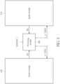
- FIG. 4 is a diagram illustrating an adjustment scheme between multi radio modules in a same radio group according to an embodiment of the present invention.
- the radio group G1 including the radio modules 108 and 118 in FIG. 1 is taken as an example.
- a processing module 200 may include circuits arranged to receive weighting information WEIGHT_I from a user or different scenarios for allocating a TX power ratio TXR1 of the radio module 108 and a TX power ratio TXR2 of the radio module 118.
- the weighting information WEIGHT_I may be predetermined fixed ratios for the TX power ratios TXR1 and TXR2 from the user or the different scenarios.
- the processing module 200 may be implemented by one of the radio modules 108 and 118 (i.e. the processing module 200 can be a part of the radio module 108 or the radio module 118), and the processing module 200 may be further arranged to interact with the other of the radio modules 108 and 118 to receive at least one message from the other of the radio modules 108 and 118, for dynamically adjusting the TX power ratios TXR1 and TXR2.
- the dynamic adjustment of the TX power ratio is performed between two radio modules in a same radio group (e.g. the radio modules 108 and 118 included in the radio group G1).
- this is for illustrative purposes only, and is not meant to be as a limitation of the present invention.
- the dynamic adjustment of the TX power ratio can be performed between more than two radio modules (e.g. the radio modules 112, 114, 116, and 120 included in the radio group G2).
- any radio module that is capable of interacting with at least one other radio module in the same radio group to receive at least one message, and dynamically adjusting the TX power ratio of any radio module at least according to the at least one message can be employed by the processing module 200.
- These alternative designs all fall within the scope of the present invention.
- the radio module 108 may be arranged to receive a time-averaged RF exposure limit regulated by officials (for brevity, hereinafter denoted by "RF exposure limit"), wherein the RF exposure limit corresponds to the radio module 108. Since the RF exposure limit is proportional to a TX power of the radio module 108, the radio module 108 may be further arranged to map the RF exposure limit to a TX power limit TPL1 of the radio module 108.
- the RF exposure limit may be a total exposure ratio (TER), wherein the TER may include a normalized average specific absorption rate (SAR) limit and a normalized average power density (PD) limit, and the TER is required to be less than or equal to 1 (i.e.
- the radio module 108 may utilize a test or a simulation to find a first normalized average TX power limit mapped to the normalized average SAR limit and a second normalized average TX power limit mapped to the normalized average PD limit, wherein the TX power limit TPL1 includes the first normalized average TX power limit and the second normalized average TX power limit.
- the user may directly utilize the test or the simulation to find the TX power limit TPL1. That is, the RF exposure limit may also be mapped to the TX power limit TPL1 of the radio module 108 directly by the user.
- the radio module 118 may be arranged to receive an RF exposure limit regulated by officials, wherein the RF exposure limit corresponds to the radio module 118. Since the RF exposure limit is proportional to a TX power of the radio module 118, the radio module 118 may be further arranged to map the RF exposure limit to a TX power limit TPL2 of the radio module 118.
- TX power limit TPL2 the radio module 118 may be further arranged to map the RF exposure limit to a TX power limit TPL2 of the radio module 118.
- the user may directly utilize the test or the simulation to find the TX power limit TPL2. That is, the RF exposure limit may also be mapped to the TX power limit TPL2 of the radio module 118 directly by the user.
- the processing module 200 may interact with the radio module 118 to receive at least one message M2 from the radio module 118, and adjust the TX power ratios TXR1 and TXR2 at least according to the at least one message M2 to obtain adjusted TX power ratios A_TXR1 and A_TXR2, respectively.
- the processing module 200 may adjust the TX power ratios TXR1 and TXR2 according to only the at least one message M2 to obtain the adjusted TX power ratios A_TXR1 and A_TXR2, respectively.
- the processing module 200 may adjust the TX power ratios TXR1 and TXR2 according to both at least one message M1 that is calculated by the radio module 108 and the at least one message M2 to obtain the adjusted TX power ratios A_TXR1 and A_TXR2, respectively. It should be noted that preferably, under a condition that the processing module 200 is not able to receive the at least one message M2 from the radio module 118 due to some reasons, the processing module 200 may adjust the TX power ratios TXR1 and TXR2 according to only the at least one message M1 to obtain the adjusted TX power ratios A_TXR1 and A_TXR2, respectively.
- the processing module 200 may adjust the TX power ratios TXR1 and TXR2 according to only the at least one message M1 to obtain the adjusted TX power ratios A_TXR1 and A_TXR2, respectively.
- the radio module 108 may be arranged to adjust the TX power limit TPL1 according to the adjusted TX power ratio A_TXR1, to generate an adjusted TX power limit ATPL1 of the radio module 108.
- the processing module 200 may interact with the radio module 108 to receive at least one message M1 from the radio module 108, and adjust the TX power ratios TXR1 and TXR2 at least according to the at least one message M1 to obtain the adjusted TX power ratios A_TXR1 and A_TXR2, respectively.
- the processing module 200 may adjust the TX power ratios TXR1 and TXR2 according to only the at least one message M1 to obtain the adjusted TX power ratios A_TXR1 and A_TXR2, respectively.
- the processing module 200 may adjust the TX power ratios TXR1 and TXR2 according to both the at least one message M1 and the at least one message M2 that is calculated by the radio module 118 to obtain the adjusted TX power ratios A_TXR1 and A_TXR2, respectively. It should be noted that preferably, under a condition that the processing module 200 is not able to receive the at least one message M1 from the radio module 108 due to some reasons, the processing module 200 may adjust the TX power ratios TXR1 and TXR2 according to only the at least one message M2 to obtain the adjusted TX power ratios A_TXR1 and A_TXR2, respectively.
- the processing module 200 may adjust the TX power ratios TXR1 and TXR2 according to only the at least one message M2 to obtain the adjusted TX power ratios A_TXR1 and A_TXR2, respectively.
- the radio module 118 may be arranged to adjust the TX power limit TPL2 according to the adjusted TX power ratio A_TXR2, to generate an adjusted TX power limit ATPL2 of the radio module 118.
- the at least one message M1 and the at least one message M2 may include an on/off status of the radio module 108 and an on/off status of the radio module 118, respectively, wherein the off status represents that corresponding radio module has not performed an TX operation for a period of time (e.g. the corresponding radio module is in a shut down mode, a flight mode, a sleep mode, a discontinuous transmission (DTX) mode, a call drop mode, or no SIM card mode), and the on status represents that the corresponding radio module is not in the off status. For example, when the corresponding radio module is not in the shut down mode, the flight mode, the sleep mode, the DTX mode, the call drop mode, or the no SIM card mode, the corresponding radio module is in the on status.
- each of the at least one message M1 and the at least one message M2 may further include some information of the corresponding radio module.
- the information of the corresponding radio module may include a previous TX power ratio, a TX power ratio margin, one or more TX performance indices, one or more receiving (RX) performance indices, one or more weighting information (e.g. the weighting information WEIGHT_I), or one or more configurations.
- the one or more TX performance indices may include at least one of a duty cycle of TX, an error vector magnitude (EVM) of TX, a target power, a throughput, a modulation and coding scheme (MCS), a block error rate (BLER), a resource block (RB), a transmission block size (TBS), and a TX packet error rate (TX PER).
- EVM error vector magnitude
- MCS modulation and coding scheme
- BLER block error rate
- RB resource block
- TBS transmission block size
- TX PER TX packet error rate
- the one or more RX performance indices may include at least one of a duty cycle of RX, a modulation and coding scheme (MCS), a block error rate (BLER), a resource block (RB), a received signal strength indication (RSSI), a reference signal receiving power (RSRP), a signal to noise ratio (SNR), a signal-to-interference-plus-noise ratio (SINR), and an RX packet error rate (RX PER).
- MCS modulation and coding scheme
- BLER block error rate
- RB resource block
- RSSI received signal strength indication
- RSRP reference signal receiving power
- SNR signal to noise ratio
- SINR signal-to-interference-plus-noise ratio
- RX PER RX packet error rate
- the one or more configurations may be related to at least one of an antenna, a band, a beam, a technology, a sub-band, one or more exposure condition indices, a simultaneous transmitted state, an MCC, an MNC, a modulation, a bandwidth, an MPR, a path, a duty cycle, and a combination of the band and an SIM.
- the processing module 200 may interact with the radio module 118 to receive the on/off status of the radio module 118 included in the at least one message M2. In response to the on/off status indicating that the radio module 118 is off, the processing module 200 may allocate at least a portion (e.g.
- the margin may be dynamically calculated according to the at least one message M1 and/or the at least one message M2.
- the processing module 200 may interact with the radio module 118 to receive the information of the radio module 118 included in the at least one message M2, and dynamically adjust the TX power ratio TXR1 of the radio module 108 and the TX power ratio TXR2 of the radio module 118 according to the information of the radio module 118 and the information of the radio module 108 included in the at least one message M1 that is calculated by the radio module 108, to obtain the adjusted TX power ratios A_TXR1 and A_TXR2.
- the processing module 200 may allocate the TX power ratio margin of the radio module 118 to the radio module 108, for dynamically adjusting the TX power ratios TXR1 and TXR2 to obtain the adjusted TX power ratios A_TXR1 and A_TXR2, respectively (e.g. increasing the TX power ratio TXR1 and correspondingly decreasing the TX power ratio TXR2 to obtain the adjusted TX power ratios A_TXR1 and A_TXR2, respectively).
- the radio module 108 may adjust the TX power limit TPL1 according to the adjusted TX power ratio A_TXR1, to generate the adjusted TX power limit ATPL1 of the radio module 108.
- the processing module 200 may interact with the radio module 108 to receive the on/off status of the radio module 108 included in the at least one message M1.
- the processing module 200 may allocate at least a portion (e.g.
- the margin may be dynamically calculated according to the at least one message M1 and/or the at least one message M2.
- the processing module 200 may interact with the radio module 108 to receive the information of the radio module 108 included in the at least one message M1, and dynamically adjust the TX power ratio TXR1 of the radio module 108 and the TX power ratio TXR2 of the radio module 118 according to the information of the radio module 108 and the information of the radio module 118 included in the at least one message M2 that is calculated by the radio module 118, to obtain the adjusted TX power ratios A_TXR1 and A_TXR2, respectively.
- the radio module 118 may adjust the TX power limit TPL2 according to the adjusted TX power ratio A_TXR2, to generate the adjusted TX power limit ATPL2 of the radio module 118.
- the radio module 108 may control an instantaneous power IP of the radio module 108 to make an average power AVP of the radio module 108 lower than or equal to the adjusted TX power limit ATPL1.
- the radio module 118 may control an instantaneous power IP of the radio module 118 to make an average power AVP of the radio module 118 lower than or equal to the adjusted TX power limit ATPL2.
- FIG. 5 please refer to FIG. 5.
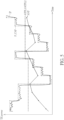
- the radio module 108/118 may be arranged to control the instantaneous power IP of the radio module 108/118 to be capped below a power cap P_CAP, to make the average power AVP of the radio module 108/118 lower than or equal to the adjusted TX power limit ATPL1/ATPL2.
- the radio module 108 may be further arranged to calculate the at least one message M1 of the radio module 108, for interacting with the radio module 118. For example, the radio module 108 may calculate the previous TX power ratio, the TX power ratio margin, the one or more TX performance indices, the one or more RX performance indices, the one or more weighting information, or the one or more configurations.
- the radio module 118 may be further arranged to calculate the at least one message M2 of the radio module 118, for interacting with the radio module 108. For brevity, similar descriptions for this embodiment are omitted.
- FIG. 6 is a flow chart of a method for adjusting a TX power ratio of a radio module according to an embodiment of the present invention. Provided that the result is substantially the same, the steps are not required to be executed in the exact order shown in FIG. 6 .
- the method shown in FIG. 6 may be employed by the radio system 12 (more particularly, the processing circuit 106) shown in FIG. 1 and the radio module 108, the radio module 118, and the processing module 200 shown in FIG. 4 .
- Step S600 the radio sets 100 and 102 are separated into the radio groups G1 and G2 according to the regulations of the SPLSR, and more particularly, the radio module 108 included in the radio set 100 and the radio module 118 included in the radio set 102 are separated into the radio group G1, and the radio modules 112, 114, and 116 in the radio set 100 and the radio module 120 in the radio set 102 are separated into the radio group G2.
- Step S602 the radio module 108 maps the RF exposure limit corresponding to the radio module 108 to the TX power limit TPL1.
- the radio module 118 maps the RF exposure limit corresponding to the radio module 118 to the TX power limit TPL2.
- Step S604 when the processing module 200 is implemented by the radio module 108, the on/off status of the radio module 118 included in the at least one message M2 is received by interacting with the radio module 118. Afterwards, it is determined that whether the on/off status indicates that the radio module 118 is on. If yes, Step S606 is entered; if no, Step S605 is entered. In addition, when the processing module 200 is implemented by the radio module 118, the on/off status of the radio module 108 included in the at least one message M1 is received by interacting with the radio module 108. Afterwards, it is determined that whether the on/off status indicates that the radio module 108 is on. If yes, Step S606 is entered; if no, Step S605 is entered.
- Step S605 when the processing module 200 is implemented by the radio module 108, in response to the on/off status indicating that the radio module 118 is off, at least a portion (e.g. part or all) of the TX power ratio TXR2 of the radio module 118 may be allocated to the TX power ratio TXR1 of the radio module 108 with a margin remained for the radio module 118, to obtain the adjusted TX power ratios A_TXR1 and A_TXR2.
- the processing module 200 when the processing module 200 is implemented by the radio module 118, in response to the on/off status indicating that the radio module 108 is off, at least a portion (e.g.
- TX power ratio TXR1 of the radio module 108 may be allocated to the TX power ratio TXR2 of the radio module 118 with a margin remained for the radio module 108, to obtain the adjusted TX power ratios A_TXR1 and A_TXR2.
- Step S606 when the processing module 200 is implemented by the radio module 108, in response to the on/off status indicating that the radio module 118 is on, the information of the radio module 118 included in the at least one message M2 is received by interacting with the radio module 118, and the TX power ratio TXR1 of the radio module 108 and the TX power ratio TXR2 of the radio module 118 are dynamically adjusted according to the information of the radio module 118 and the information of the radio module 108 included in the at least one message M1, to obtain the adjusted TX power ratios A_TXR1 and A_TXR2, respectively.
- the processing module 200 when the processing module 200 is implemented by the radio module 118, in response to the on/off status indicating that the radio module 108 is on, the information of the radio module 108 included in the at least one message M1 is received by interacting with the radio module 108, and the TX power ratio TXR1 of the radio module 108 and the TX power ratio TXR2 of the radio module 118 are dynamically adjusted according to the information of the radio module 108 and the information of the radio module 118 included in the at least one message M2, to obtain the adjusted TX power ratios A_TXR1 and A_TXR2, respectively.
- Step S608 the radio module 108 adjusts the TX power limit TPL1 according to the adjusted TX power ratio A_TXR1, to generate the adjusted TX power limit ATPL1. Similarly, the radio module 118 adjusts the TX power limit TPL2 according to the adjusted TX power ratio A_TXR2, to generate the adjusted TX power limit ATPL2.
- Step S610 the radio module 108 controls the instantaneous power IP of the radio module 108 to make the average power AVP of the radio module 108 lower than or equal to the adjusted TX power limit ATPL1.
- the radio module 118 controls the instantaneous power IP of the radio module 118 to make the average power AVP of the radio module 118 lower than or equal to the adjusted TX power limit ATPL2.
- Step S612 after the average power AVP of the radio module 108 is controlled to be lower than or equal to the adjusted TX power limit ATPL1, the radio module 108 calculates the at least one message M1 for interacting with the radio module 118. Similarly, after the average power AVP of the radio module 118 is controlled to be lower than or equal to the adjusted TX power limit ATPL2, the radio module 118 calculates the at least one message M2 for interacting with the radio module 108.
- multiple radio modules are separated into multiple radio groups according to an RF regulation related to the SPLSR for calculating respective TER of the radio groups, which can make the radio groups easy to comply with the TER regulation, and therefore can increase design flexibility.
- the others of the radio modules in the radio group may be able to utilize the TX power margin for dynamically adjusting the TX power ratios of the others of the multiple radio modules and the TX power ratio of the any of the multiple radio modules (e.g.
- the others of the multiple radio modules may be able to utilize the TX power margin for further dynamic adjustment. In this way, ratio efficiency and performance can be improved.
Landscapes
- Engineering & Computer Science (AREA)
- Computer Networks & Wireless Communication (AREA)
- Signal Processing (AREA)
- Mobile Radio Communication Systems (AREA)
- Transmitters (AREA)
Abstract
Description
- This application claims the benefit of
U.S. Provisional Application No. 63/347,050 - The present invention is related to radiofrequency (RF) technology, and more particularly, to a method for adjusting a transmitting (TX) power ratio of a radio module and an associated radio system.
- Nowadays, the RF technology has often appeared in a user equipment (UE; such as a mobile phone). However, excessive RF exposure may cause harm to human body. As a result, officials of different countries (e.g. federal communications commission (FCC) of USA, innovation, science, and economic development (ISED) of Canada, and conformite europeenne (CE) of Europe) regulate a time-averaged RF exposure limit to limit a time-averaged RF exposure of a radio module in the UE. For example, in response to a frequency band of the radio module being smaller than 6 GHz, the time-averaged RF exposure will be quantified with a time-averaged specific absorption rate (SAR), and in response to the frequency band of the radio module being not smaller than 6 GHz, the time-averaged RF exposure will be quantified with a time-averaged power density (PD) . In addition, since the time-averaged RF exposure will be proportional to a TX power of the radio module, the time-averaged RF exposure can meet the time-averaged RF exposure limit by controlling the TX power.
- For simultaneous multi-radio access technology (multi-RAT) transmission (e.g. 2G, 3G, 4G, FR1, FR2, wireless fidelity (Wi-Fi), and Bluetooth (BT)), the officials regulate that a total exposure ratio (TER) must be less than or equal to 1 (i.e. TER ≤ 1). How to properly allocate the TX power of multiple radio modules in the UE to meet regulations and performance requirements at the same time has become an important issue. For a conventional TX power allocation method, all of the radio modules may be regarded as a single radio group, and all of RF exposure caused by the radio modules in the single radio group is combined to calculate the TER of the single radio group, which makes the individual radio modules difficult to comply with the TER regulation. In addition, only the maximum available TX power ratio is allocated to the radio modules with a predetermined fixed ratio. The disadvantage is that even if any of the radio modules only needs a TX power ratio less than the predetermined fixed ratio (i.e. one radio module will have a TX power margin remained unused), the others of the radio modules may not be able to utilize the TX power margin, which will reduce ratio efficiency and performance. As a result, a novel method for adjusting a TX power ratio of a radio module and an associated radio system are urgently needed.
- It is therefore one of the objectives of the present invention to provide a method for adjusting a TX power ratio of a radio module, which separates multiple radio modules into multiple radio groups according to an RF regulation related to the SPLSR for calculating respective TER of the radio groups, and an associated radio system, to address the above-mentioned issues. A method and a radio system according to the invention are defined in the independent claims. The dependent claims define preferred embodiments thereof.
- According to an embodiment of the present invention, a method for adjusting a TX power ratio of a radio module is provided. The method comprises: separating multiple radio modules into multiple radio groups according to an RF regulation, wherein the multiple radio modules comprise the radio module; mapping an RF exposure limit to a TX power limit; interacting with at least one other radio module for adjusting the TX power ratio, to obtain at least one adjusted TX power ratio, wherein the multiple radio modules comprise the at least one other radio module, and the radio module and the at least one other radio module are comprised in a same radio group of the multiple radio groups; and adjusting the TX power limit according to the at least one adjusted TX power ratio, to generate an adjusted TX power limit of the radio module.
- According to an embodiment of the present invention, a radio system for adjusting a TX power ratio of a radio module is provided. The radio system comprises a processing circuit and the radio module. The processing circuit is arranged to separate multiple radio modules into multiple radio groups according to an RF regulation, wherein the multiple radio modules comprise the radio module. The radio module is arranged to: map an RF exposure limit to a TX power limit; interact with at least one other radio module for adjusting the TX power ratio, to obtain at least one adjusted TX power ratio, wherein the radio module and the at least one other radio module are comprised in a same radio group of the multiple radio groups; and adjust the TX power limit according to the at least one adjusted TX power ratio, to generate an adjusted TX power limit of the radio module.
- One of the benefits of the present invention is that, by the method of the present invention and an associated radio system, multiple radio modules are separated into multiple radio groups according to an RF regulation related to the SPLSR for calculating respective TER of the radio groups, which can make the radio groups easy to comply with the TER regulation, and therefore can increase design flexibility. In addition, for each radio group, in the beginning, under a condition that any of the radio modules in the radio group only needs a TX power ratio less than a predetermined fixed ratio (i.e. one radio module will have a TX power margin remained unused), the others of the radio modules in the radio group may be able to utilize the TX power margin for dynamically adjusting the TX power ratios of the others of the multiple radio modules and the TX power ratio of the any of the multiple radio modules (e.g. increasing the TX power ratios of the others of the multiple radio modules and correspondingly decreasing the TX power ratio of the any of the multiple radio modules). Afterwards, under a condition that the any of multiple radio modules still only needs a current TX power ratio less than a previous adjusted TX power ratio (i.e. the one radio module will still have the TX power margin remained unused), the others of the multiple radio modules may be able to utilize the TX power margin for further dynamic adjustment. In this way, ratio efficiency and performance can be improved.
- These and other objectives of the present invention will no doubt become obvious to those of ordinary skill in the art after reading the following detailed description of the preferred embodiment that is illustrated in the various figures and drawings.
-
-
FIG. 1 is a diagram illustrating an electronic device according to an embodiment of the present invention. -
FIG. 2 is a timing diagram of activation of time ticks of multiple radio groups according to an embodiment of the present invention. -
FIG. 3 is a timing diagram of activation of time ticks of multiple radio groups according to another embodiment of the present invention. -
FIG. 4 is a diagram illustrating an adjustment scheme between two radio modules in a same radio group according to an embodiment of the present invention. -
FIG. 5 is a diagram illustrating a control scheme of an instantaneous power of a radio module according to an embodiment of the present invention. -
FIG. 6 is a flow chart of a method for adjusting a TX power ratio of a radio module according to an embodiment of the present invention. - Certain terms are used throughout the following description and claims, which refer to particular components. As one skilled in the art will appreciate, electronic equipment manufacturers may refer to a component by different names. This document does not intend to distinguish between components that differ in name but not in function. In the following description and in the claims, the terms "include" and "comprise" are used in an open-ended fashion, and thus should be interpreted to mean "include, but not limited to ...".
-
FIG. 1 is a diagram illustrating anelectronic device 10 according to an embodiment of the present invention. By way of example, but not limitation, theelectronic device 10 may be a portable device such as a smartphone, a wearable device, or a tablet. As shown inFIG. 1 , theelectronic device 10 may include aradio system 12 and astorage device 105, wherein theradio system 12 may includemultiple radio sets processing circuit 106, theradio set 100 may includemultiple radio modules radio set 102 may includemultiple radio modules radio set 104 may include aradio module 122. Each of theradio modules radio set 100 may be a cellular radio set corresponding to sub-6 (i.e. theradio modules radio set 102 may be a cellular radio set corresponding to mmWave (i.e. theradio modules radio set 104 may be a connectivity system radio set corresponding to Wi-Fi and/or BT (i.e. theradio module 122 includes communication circuits corresponding to Wi-Fi and/or BT). - The
processing circuit 106 may be a single-core processor or a multi-core processor. Thestorage device 105 is a non-transitory machine-readable medium, and is arranged to store computer program code PROG. Theelectronic device 10 may be regarded as a computer system using a computer program product that includes a computer-readable medium containing the computer program code PROG. Theprocessing circuit 106 is equipped with software execution capability. When loaded and executed by theprocessing circuit 106, the computer program code PROG instructs theprocessing circuit 106 to separate multiple radio sets (e.g. theradio sets 
- For 1g SAR, the SPLSR equation is regulated to be less than or equal to 0.04 (i.e.


- In this embodiment, the
processing circuit 106 may separate theradio sets radio module 108 included in theradio set 100 and theradio module 118 included in theradio set 102 into the radio group G1, and separate theradio modules radio set 100 and theradio module 120 in theradio set 102 into the radio group G2. Since any radio module in the radio group G1 and any radio module in the radio group G2 (e.g. theradio module 108 and the radio 112) satisfy the above-mentioned regulations of the SPLSR, the TER calculation of the radio group G1 and the TER calculation of the radio group G2 can be independent. That is, a sum of the TER of any radio module (s) in the radio group G1 and the TER of any radio module(s) in the radio group G2 can be greater than 1. For example, a sum of the TER of theradio module 108 in the radio group G1 and the TER of theradio module 112 in the radio group G2 can be greater than 1. - However, the radio group separation in this embodiment is for illustrative purposes only, and is not meant to be as a limitation of the present invention. Preferably, the
processing circuit 106 may separate the radio sets 100 and 104 into a radio group according to the regulations of the SPLSR, and more particularly, may separate theradio modules radio set 100 and theradio module 122 included in the radio set 104 into the radio group. Preferably, theprocessing circuit 106 may separate the radio sets 102 and 104 into a radio group according to the regulations of the SPLSR, and more particularly, may separate theradio module 118 included in theradio set 102 and theradio module 122 included in the radio set 104 into the radio group. These alternative designs all fall within the scope of the present invention. - In addition, a plurality of indicators can be utilized to identify the radio groups G1 and G2 between the radio sets 100 and 102.
Table 1 Radio set 100 Radio module 108Radio module 110Radio module 112Radio module 114Radio module 116Radio set Radio module #a1 102 118 Radio module 120#a2 #a2 #a2 - Table 1 illustrates an example of indicators #a1 and #a2 utilized to identify the radio groups G1 and G2 between the radio sets 100 and 102, wherein the indicator #a1 indicates that the
radio module 108 in theradio set 100 and theradio module 118 in the radio set 102 are in the radio group G1, and the indicators #a2 indicate that theradio modules radio set 100 and theradio module 120 in the radio set 102 are in the radio group G2. - In addition, for each of the radio groups G1 and G2, the
processing circuit 106 may be further arranged to start to activate a time tick corresponding to the each of the radio groups G1 and G2 according to one or more configurations corresponding to the each of the radio groups G1 and G2, for calculating respective TERs. By way of example, but not limitation, the one or more configurations may be related to at least one of an antenna, a band, a beam, a technology, a sub-band, one or more exposure condition indices, a simultaneous transmitted state, a mobile country code (MCC), a mobile network code (MNC), a modulation, a bandwidth, a maximum power reduction (MPR), a path, a duty cycle, and a combination of the band and an subscriber identity module (SIM) . In detail, please refer toFIG. 2. FIG. 2 is a timing diagram of activation of time ticks of the radio groups G1 and G2 according to an embodiment of the present invention. In this embodiment, the one or more configurations are related to the band. As shown inFIG. 2 , at a time point t0, a band BAND_1 of the radio group G1 is activated. At this moment, theprocessing circuit 106 may be arranged to start to activate a time tick corresponding to the radio group G1 for calculating the TER of the radio group G1. At a time point t1, a band BAND_2 of the radio group G2 is activated. At this moment, theprocessing circuit 106 may be arranged to start to activate a time tick corresponding to the radio group G2 for calculating the TER of the radio group G2. In this way, the TER calculation of the radio group G1 and the TER calculation of the radio group G2 are independent. -
FIG. 3 is a timing diagram of activation of time ticks of the radio groups G1 and G2 according to another embodiment of the present invention. The difference between the timing diagram shown inFIG. 2 and the timing diagram shown inFIG. 3 is that the band BAND_2 of the radio group G2 is inactivated for at least a period of time in the timing diagram shown inFIG. 3 . For example, the band BAND_2 of the radio group G2 is inactivated since a time point t2, and after the period of time (e.g. from the time point t2 to a time point t3; for brevity, labeled as "P_TIME" inFIG. 3 ) has elapsed, theprocessing circuit 106 may be arranged to start to inactivate the time tick corresponding to the radio group G2 (e.g. turn off the radio group G2) at the time point t3, to stop calculating the TER of the radio group G2. -
FIG. 4 is a diagram illustrating an adjustment scheme between multi radio modules in a same radio group according to an embodiment of the present invention. For better comprehension, the radio group G1 including theradio modules FIG. 1 is taken as an example. As shown inFIG. 4 , aprocessing module 200 may include circuits arranged to receive weighting information WEIGHT_I from a user or different scenarios for allocating a TX power ratio TXR1 of theradio module 108 and a TX power ratio TXR2 of theradio module 118. For example, the weighting information WEIGHT_I may be predetermined fixed ratios for the TX power ratios TXR1 and TXR2 from the user or the different scenarios. It should be noted that theprocessing module 200 may be implemented by one of theradio modules 108 and 118 (i.e. theprocessing module 200 can be a part of theradio module 108 or the radio module 118), and theprocessing module 200 may be further arranged to interact with the other of theradio modules radio modules radio modules radio modules processing module 200. These alternative designs all fall within the scope of the present invention. - In this embodiment, the
radio module 108 may be arranged to receive a time-averaged RF exposure limit regulated by officials (for brevity, hereinafter denoted by "RF exposure limit"), wherein the RF exposure limit corresponds to theradio module 108. Since the RF exposure limit is proportional to a TX power of theradio module 108, theradio module 108 may be further arranged to map the RF exposure limit to a TX power limit TPL1 of theradio module 108. Specifically, the RF exposure limit may be a total exposure ratio (TER), wherein the TER may include a normalized average specific absorption rate (SAR) limit and a normalized average power density (PD) limit, and the TER is required to be less than or equal to 1 (i.e. TER ≤ 1). Theradio module 108 may utilize a test or a simulation to find a first normalized average TX power limit mapped to the normalized average SAR limit and a second normalized average TX power limit mapped to the normalized average PD limit, wherein the TX power limit TPL1 includes the first normalized average TX power limit and the second normalized average TX power limit. However, this is for illustration only, and the present invention is not limited thereto. Preferably, the user may directly utilize the test or the simulation to find the TX power limit TPL1. That is, the RF exposure limit may also be mapped to the TX power limit TPL1 of theradio module 108 directly by the user. Similarly, theradio module 118 may be arranged to receive an RF exposure limit regulated by officials, wherein the RF exposure limit corresponds to theradio module 118. Since the RF exposure limit is proportional to a TX power of theradio module 118, theradio module 118 may be further arranged to map the RF exposure limit to a TX power limit TPL2 of theradio module 118. However this is for illustration only, and the present invention is not limited thereto. Preferably, the user may directly utilize the test or the simulation to find the TX power limit TPL2. That is, the RF exposure limit may also be mapped to the TX power limit TPL2 of theradio module 118 directly by the user. - Under a condition that the
processing module 200 is implemented by theradio module 108, theprocessing module 200 may interact with theradio module 118 to receive at least one message M2 from theradio module 118, and adjust the TX power ratios TXR1 and TXR2 at least according to the at least one message M2 to obtain adjusted TX power ratios A_TXR1 and A_TXR2, respectively. For example, theprocessing module 200 may adjust the TX power ratios TXR1 and TXR2 according to only the at least one message M2 to obtain the adjusted TX power ratios A_TXR1 and A_TXR2, respectively. For another example, theprocessing module 200 may adjust the TX power ratios TXR1 and TXR2 according to both at least one message M1 that is calculated by theradio module 108 and the at least one message M2 to obtain the adjusted TX power ratios A_TXR1 and A_TXR2, respectively. It should be noted that preferably, under a condition that theprocessing module 200 is not able to receive the at least one message M2 from theradio module 118 due to some reasons, theprocessing module 200 may adjust the TX power ratios TXR1 and TXR2 according to only the at least one message M1 to obtain the adjusted TX power ratios A_TXR1 and A_TXR2, respectively. Preferably, after theprocessing module 200 receives the at least one message M2 from theradio module 118 by interacting with theradio module 118, the at least one message M2 may be stored in a memory (not shown inFIG. 4 ), and theprocessing module 200 may adjust the TX power ratios TXR1 and TXR2 according to only the at least one message M1 to obtain the adjusted TX power ratios A_TXR1 and A_TXR2, respectively. These alternative designs all fall within the scope of the present invention. Theradio module 108 may be arranged to adjust the TX power limit TPL1 according to the adjusted TX power ratio A_TXR1, to generate an adjusted TX power limit ATPL1 of theradio module 108. - In addition, under a condition that the
processing module 200 is implemented by theradio module 118, theprocessing module 200 may interact with theradio module 108 to receive at least one message M1 from theradio module 108, and adjust the TX power ratios TXR1 and TXR2 at least according to the at least one message M1 to obtain the adjusted TX power ratios A_TXR1 and A_TXR2, respectively. For example, theprocessing module 200 may adjust the TX power ratios TXR1 and TXR2 according to only the at least one message M1 to obtain the adjusted TX power ratios A_TXR1 and A_TXR2, respectively. For another example, theprocessing module 200 may adjust the TX power ratios TXR1 and TXR2 according to both the at least one message M1 and the at least one message M2 that is calculated by theradio module 118 to obtain the adjusted TX power ratios A_TXR1 and A_TXR2, respectively. It should be noted that preferably, under a condition that theprocessing module 200 is not able to receive the at least one message M1 from theradio module 108 due to some reasons, theprocessing module 200 may adjust the TX power ratios TXR1 and TXR2 according to only the at least one message M2 to obtain the adjusted TX power ratios A_TXR1 and A_TXR2, respectively. Preferably, after theprocessing module 200 receives the at least one message M1 from theradio module 108 by interacting with theradio module 108, the at least one message M1 may be stored in a memory (not shown inFIG. 4 ), and theprocessing module 200 may adjust the TX power ratios TXR1 and TXR2 according to only the at least one message M2 to obtain the adjusted TX power ratios A_TXR1 and A_TXR2, respectively. These alternative designs all fall within the scope of the present invention. Theradio module 118 may be arranged to adjust the TX power limit TPL2 according to the adjusted TX power ratio A_TXR2, to generate an adjusted TX power limit ATPL2 of theradio module 118. - The at least one message M1 and the at least one message M2 may include an on/off status of the
radio module 108 and an on/off status of theradio module 118, respectively, wherein the off status represents that corresponding radio module has not performed an TX operation for a period of time (e.g. the corresponding radio module is in a shut down mode, a flight mode, a sleep mode, a discontinuous transmission (DTX) mode, a call drop mode, or no SIM card mode), and the on status represents that the corresponding radio module is not in the off status. For example, when the corresponding radio module is not in the shut down mode, the flight mode, the sleep mode, the DTX mode, the call drop mode, or the no SIM card mode, the corresponding radio module is in the on status. In addition, each of the at least one message M1 and the at least one message M2 may further include some information of the corresponding radio module. By way of example, but not limitation, the information of the corresponding radio module may include a previous TX power ratio, a TX power ratio margin, one or more TX performance indices, one or more receiving (RX) performance indices, one or more weighting information (e.g. the weighting information WEIGHT_I), or one or more configurations. - The one or more TX performance indices may include at least one of a duty cycle of TX, an error vector magnitude (EVM) of TX, a target power, a throughput, a modulation and coding scheme (MCS), a block error rate (BLER), a resource block (RB), a transmission block size (TBS), and a TX packet error rate (TX PER). The one or more RX performance indices may include at least one of a duty cycle of RX, a modulation and coding scheme (MCS), a block error rate (BLER), a resource block (RB), a received signal strength indication (RSSI), a reference signal receiving power (RSRP), a signal to noise ratio (SNR), a signal-to-interference-plus-noise ratio (SINR), and an RX packet error rate (RX PER). The one or more configurations may be related to at least one of an antenna, a band, a beam, a technology, a sub-band, one or more exposure condition indices, a simultaneous transmitted state, an MCC, an MNC, a modulation, a bandwidth, an MPR, a path, a duty cycle, and a combination of the band and an SIM.
- In detail, under a condition that the
processing module 200 is implemented by theradio module 108, in the beginning, theprocessing module 200 may interact with theradio module 118 to receive the on/off status of theradio module 118 included in the at least one message M2. In response to the on/off status indicating that theradio module 118 is off, theprocessing module 200 may allocate at least a portion (e.g. part or all) of the TX power ratio TXR2 of theradio module 118 to the TX power ratio TXR1 of theradio module 108 with a margin remained for theradio module 118, to obtain the adjusted TX power ratios A_TXR1 and A_TXR2, wherein the margin may be dynamically calculated according to the at least one message M1 and/or the at least one message M2. In response to the on/off status indicating that theradio module 118 is on, theprocessing module 200 may interact with theradio module 118 to receive the information of theradio module 118 included in the at least one message M2, and dynamically adjust the TX power ratio TXR1 of theradio module 108 and the TX power ratio TXR2 of theradio module 118 according to the information of theradio module 118 and the information of theradio module 108 included in the at least one message M1 that is calculated by theradio module 108, to obtain the adjusted TX power ratios A_TXR1 and A_TXR2. For example, under a condition that the weighting information WEIGHT_I indicates that the predetermined fixed ratio for theradio module 118 is 0.4 and the actual used TX power ratio of theradio module 118 is 0.2, the TX power ratio margin of theradio module 118 is 0.2, and theprocessing module 200 may allocate the TX power ratio margin of theradio module 118 to theradio module 108, for dynamically adjusting the TX power ratios TXR1 and TXR2 to obtain the adjusted TX power ratios A_TXR1 and A_TXR2, respectively (e.g. increasing the TX power ratio TXR1 and correspondingly decreasing the TX power ratio TXR2 to obtain the adjusted TX power ratios A_TXR1 and A_TXR2, respectively). Afterwards, theradio module 108 may adjust the TX power limit TPL1 according to the adjusted TX power ratio A_TXR1, to generate the adjusted TX power limit ATPL1 of theradio module 108. - Similarly, under a condition that the
processing module 200 is implemented by theradio module 118, in the beginning, theprocessing module 200 may interact with theradio module 108 to receive the on/off status of theradio module 108 included in the at least one message M1. In response to the on/off status indicating that theradio module 108 is off, theprocessing module 200 may allocate at least a portion (e.g. part or all) of the TX power ratio TXR1 of theradio module 108 to the TX power ratio TXR2 of theradio module 118 with a margin remained for theradio module 108, to obtain the adjusted TX power ratios A_TXR1 and A_TXR2, wherein the margin may be dynamically calculated according to the at least one message M1 and/or the at least one message M2. In response to the on/off status indicating that theradio module 108 is on, theprocessing module 200 may interact with theradio module 108 to receive the information of theradio module 108 included in the at least one message M1, and dynamically adjust the TX power ratio TXR1 of theradio module 108 and the TX power ratio TXR2 of theradio module 118 according to the information of theradio module 108 and the information of theradio module 118 included in the at least one message M2 that is calculated by theradio module 118, to obtain the adjusted TX power ratios A_TXR1 and A_TXR2, respectively. Afterwards, theradio module 118 may adjust the TX power limit TPL2 according to the adjusted TX power ratio A_TXR2, to generate the adjusted TX power limit ATPL2 of theradio module 118. - After generating the adjusted TX power limit ATPL1, the
radio module 108 may control an instantaneous power IP of theradio module 108 to make an average power AVP of theradio module 108 lower than or equal to the adjusted TX power limit ATPL1. Similarly, after generating the adjusted TX power limit ATPL2, theradio module 118 may control an instantaneous power IP of theradio module 118 to make an average power AVP of theradio module 118 lower than or equal to the adjusted TX power limit ATPL2. Specifically, please refer toFIG. 5. FIG. 5 is a diagram illustrating a control scheme of the instantaneous power of theradio module 108/118 according to an embodiment of the present invention, wherein the horizontal axis of the diagram represents time, and the vertical axis of the diagram represents TX power of theradio module 108/118. As shown inFIG. 5 , in order to comply with regulations of the RF exposure limit, theradio module 108/118 may be arranged to control the instantaneous power IP of theradio module 108/118 to be capped below a power cap P_CAP, to make the average power AVP of theradio module 108/118 lower than or equal to the adjusted TX power limit ATPL1/ATPL2. Since operations of the power cap P_CAP are well known to those with ordinary knowledge in the art, and the focus of the present invention is on the radio group separation and dynamic adjustment for the TX power ratio TXR1/TXR2 of theradio module 108/118 in the same radio group G1, the details of the operations of the power cap P_CAP will be omitted for brevity. - After the average power AVP of the
radio module 108 is controlled to be lower than or equal to the adjusted TX power limit ATPL1 of theradio module 108, theradio module 108 may be further arranged to calculate the at least one message M1 of theradio module 108, for interacting with theradio module 118. For example, theradio module 108 may calculate the previous TX power ratio, the TX power ratio margin, the one or more TX performance indices, the one or more RX performance indices, the one or more weighting information, or the one or more configurations. Similarly, after the average power AVP of theradio module 118 is controlled to be lower than or equal to the adjusted TX power limit ATPL2 of theradio module 118, theradio module 118 may be further arranged to calculate the at least one message M2 of theradio module 118, for interacting with theradio module 108. For brevity, similar descriptions for this embodiment are omitted. -
FIG. 6 is a flow chart of a method for adjusting a TX power ratio of a radio module according to an embodiment of the present invention. Provided that the result is substantially the same, the steps are not required to be executed in the exact order shown inFIG. 6 . For example, regarding the separation of the radio sets 100 and 102 and the adjustment of TX power ratios TXR1 and TXR2 of theradio modules FIG. 6 may be employed by the radio system 12 (more particularly, the processing circuit 106) shown inFIG. 1 and theradio module 108, theradio module 118, and theprocessing module 200 shown inFIG. 4 . - In Step S600, the radio sets 100 and 102 are separated into the radio groups G1 and G2 according to the regulations of the SPLSR, and more particularly, the
radio module 108 included in theradio set 100 and theradio module 118 included in the radio set 102 are separated into the radio group G1, and theradio modules radio set 100 and theradio module 120 in the radio set 102 are separated into the radio group G2. - In Step S602, the
radio module 108 maps the RF exposure limit corresponding to theradio module 108 to the TX power limit TPL1. Similarly, theradio module 118 maps the RF exposure limit corresponding to theradio module 118 to the TX power limit TPL2. - In Step S604, when the
processing module 200 is implemented by theradio module 108, the on/off status of theradio module 118 included in the at least one message M2 is received by interacting with theradio module 118. Afterwards, it is determined that whether the on/off status indicates that theradio module 118 is on. If yes, Step S606 is entered; if no, Step S605 is entered. In addition, when theprocessing module 200 is implemented by theradio module 118, the on/off status of theradio module 108 included in the at least one message M1 is received by interacting with theradio module 108. Afterwards, it is determined that whether the on/off status indicates that theradio module 108 is on. If yes, Step S606 is entered; if no, Step S605 is entered. - In Step S605, when the
processing module 200 is implemented by theradio module 108, in response to the on/off status indicating that theradio module 118 is off, at least a portion (e.g. part or all) of the TX power ratio TXR2 of theradio module 118 may be allocated to the TX power ratio TXR1 of theradio module 108 with a margin remained for theradio module 118, to obtain the adjusted TX power ratios A_TXR1 and A_TXR2. In addition, when theprocessing module 200 is implemented by theradio module 118, in response to the on/off status indicating that theradio module 108 is off, at least a portion (e.g. part or all) of the TX power ratio TXR1 of theradio module 108 may be allocated to the TX power ratio TXR2 of theradio module 118 with a margin remained for theradio module 108, to obtain the adjusted TX power ratios A_TXR1 and A_TXR2. - In Step S606, when the
processing module 200 is implemented by theradio module 108, in response to the on/off status indicating that theradio module 118 is on, the information of theradio module 118 included in the at least one message M2 is received by interacting with theradio module 118, and the TX power ratio TXR1 of theradio module 108 and the TX power ratio TXR2 of theradio module 118 are dynamically adjusted according to the information of theradio module 118 and the information of theradio module 108 included in the at least one message M1, to obtain the adjusted TX power ratios A_TXR1 and A_TXR2, respectively. In addition, when theprocessing module 200 is implemented by theradio module 118, in response to the on/off status indicating that theradio module 108 is on, the information of theradio module 108 included in the at least one message M1 is received by interacting with theradio module 108, and the TX power ratio TXR1 of theradio module 108 and the TX power ratio TXR2 of theradio module 118 are dynamically adjusted according to the information of theradio module 108 and the information of theradio module 118 included in the at least one message M2, to obtain the adjusted TX power ratios A_TXR1 and A_TXR2, respectively. - In Step S608, the
radio module 108 adjusts the TX power limit TPL1 according to the adjusted TX power ratio A_TXR1, to generate the adjusted TX power limit ATPL1. Similarly, theradio module 118 adjusts the TX power limit TPL2 according to the adjusted TX power ratio A_TXR2, to generate the adjusted TX power limit ATPL2. - In Step S610, the
radio module 108 controls the instantaneous power IP of theradio module 108 to make the average power AVP of theradio module 108 lower than or equal to the adjusted TX power limit ATPL1. Similarly, theradio module 118 controls the instantaneous power IP of theradio module 118 to make the average power AVP of theradio module 118 lower than or equal to the adjusted TX power limit ATPL2. - In Step S612, after the average power AVP of the
radio module 108 is controlled to be lower than or equal to the adjusted TX power limit ATPL1, theradio module 108 calculates the at least one message M1 for interacting with theradio module 118. Similarly, after the average power AVP of theradio module 118 is controlled to be lower than or equal to the adjusted TX power limit ATPL2, theradio module 118 calculates the at least one message M2 for interacting with theradio module 108. - Since a person skilled in the pertinent art can readily understand details of the steps after reading above paragraphs directed to the
processing circuit 106 shown inFIG. 1 and theradio module 108, theradio module 118, and theprocessing module 200 shown inFIG. 4 , and the adjustment of the TX power ratios of theradio modules radio modules - In summary, by the method of the present invention and an associated radio system, multiple radio modules are separated into multiple radio groups according to an RF regulation related to the SPLSR for calculating respective TER of the radio groups, which can make the radio groups easy to comply with the TER regulation, and therefore can increase design flexibility. In addition, for each radio group, in the beginning, under a condition that any of the radio modules in the radio group only needs a TX power ratio less than a predetermined fixed ratio (i.e. one radio module will have a TX power margin remained unused), the others of the radio modules in the radio group may be able to utilize the TX power margin for dynamically adjusting the TX power ratios of the others of the multiple radio modules and the TX power ratio of the any of the multiple radio modules (e.g. increasing the TX power ratios of the others of the multiple radio modules and correspondingly decreasing the TX power ratio of the any of the multiple radio modules) . Afterwards, under a condition that the any of multiple radio modules still only needs a current TX power ratio less than a previous adjusted TX power ratio (i.e. the one radio module will still have the TX power margin remained unused), the others of the multiple radio modules may be able to utilize the TX power margin for further dynamic adjustment. In this way, ratio efficiency and performance can be improved.
- Those skilled in the art will readily observe that numerous modifications and alterations of the device and method may be made while retaining the teachings of the invention. Accordingly, the above disclosure should be construed as limited only by the metes and bounds of the appended claims.
Claims (15)
- A method for adjusting a transmitting, in the following also referred to as TX, power ratio of a radio module, comprising:separating multiple radio modules into multiple radio groups according to a radiofrequency, in the following also referred to as RF, regulation, wherein the multiple radio modules comprise the radio module (S600);mapping an RF exposure limit to a TX power limit (S602);interacting with at least one other radio module for adjusting the TX power ratio, to obtain at least one adjusted TX power ratio, wherein the multiple radio modules comprise the at least one other radio module, and the radio module and the at least one other radio module are comprised in a same radio group of the multiple radio groups (S604, S606); andadjusting the TX power limit according to the at least one adjusted TX power ratio, to generate an adjusted TX power limit of the radio module (S608).
- A radio system (12) for adjusting a transmitting, in the following also referred to as TX, power ratio of a radio module, comprising:a processing circuit (106), arranged to separate multiple radio modules (108, 110, 112, 114, 116, 118, 120, 122) into multiple radio groups (G1, G2) according to a radiofrequency, in the following also referred to as RF, regulation, wherein the multiple radio modules (108, 110, 112, 114, 116, 118, 120, 122) comprise the radio module; andthe radio module, arranged to:map an RF exposure limit to a TX power limit;interact with at least one other radio module for adjusting the TX power ratio, to obtain at least one adjusted TX power ratio, wherein the radio module and the at least one other radio module are comprised in a same radio group of the multiple radio groups (G1, G2); andadjust the TX power limit according to the at least one adjusted TX power ratio, to generate an adjusted TX power limit of the radio module.
- The method of claim 1 or the radio system of claim 2, wherein the RF regulation is related to a specific absorption rate to peak location separation ratio, in the following also referred to as SPLSR, and a total exposure ratio, in the following also referred to as TER, calculation of each of the multiple radio groups is independent.
- The method of claim 1 or 3, wherein the step of interacting with the at least one other radio module for adjusting the TX power ratio, to obtain the at least one adjusted TX power ratio comprises:receiving at least one message of the at least one other radio module, andadjusting the TX power ratio at least according to the at least one message of the at least one other radio module, to obtain the at least one adjusted TX power ratio; orthe radio system of claim 2 or 3, wherein the radio module is further arranged to receive at least one message of the at least one other radio module, and adjust the TX power ratio at least according to the at least one message of the at least one other radio module, to obtain the at least one adjusted TX power ratio.
- The method or the radio system of claim 4, wherein the at least one message of the at least one other radio module comprises an on/off status of the at least one other radio module.
- The method of claim 5, wherein the step of adjusting the TX power ratio at least according to the at least one message of the at least one other radio module, to obtain the at least one adjusted TX power ratio comprises:in response to the on/off status indicating that the at least one other radio module is off, allocating a TX power ratio of the at least one other radio module to the radio module with a margin remained for the at least one other radio module; orthe radio system of claim 5, wherein in response to the on/off status indicating that the at least one other radio module is off,the radio module allocates a TX power ratio of the at least one other radio module to the radio module with a margin remained for the at least one other radio module.
- The method of claim 5 or 6, wherein the step of adjusting the TX power ratio at least according to the at least one message of the at least one other radio module, to obtain the at least one adjusted TX power ratio comprises:in response to the on/off status indicating that the at least one other radio module is on, dynamically adjusting the TX power ratio according to the at least one message of the at least one other radio module and at least one message of the radio module; orthe radio system of claim 5 or 6, wherein in response to the on/off status indicating that the at least one other radio module is on,the radio module dynamically adjusts the TX power ratio according to the at least one message of the at least one other radio module and at least one message of the radio module.
- The method or the radio system of claim 7, wherein each of the at least one message of the at least one other radio module and the at least one message of the radio module comprises a previous TX power ratio, a TX power ratio margin, one or more TX performance indices, one or more receiving, in the following also referred to as RX, performance indices, one or more weighting information, or one or more configurations.
- The method or the radio system of claim 7 or 8, wherein each of the at least one message of the at least one other radio module and the at least one message of the radio module comprises the one or more TX performance indices, including at least one of a duty cycle of TX, an error vector magnitude, in the following also referred to as EVM, of TX, a target power, a throughput, a modulation and coding scheme, in the following also referred to as MCS, a block error rate, in the following also referred to as BLER, a resource block, in the following also referred to as RB, a transmission block size, in the following also referred to as TBS, and a TX packet error rate, in the following also referred to as TX PER; and/or
wherein each of the at least one message of the at least one other radio module and the at least one message of the radio module comprises the one or more RX performance indices, including at least one of a duty cycle of RX, a modulation and coding scheme, in the following also referred to as MCS, a block error rate, in the following also referred to as BLER, a resource block, in the following also referred to as RB, a received signal strength indication, in the following also referred to as RSSI, a reference signal RX power, in the following also referred to as RSRP, a signal to noise ratio, in the following also referred to as SNR, a signal to interference plus noise ratio, in the following also referred to as SINR, and an RX packet error rate, in the following also referred to as RX PER. - The method or the radio system of any one of claims 7 to 9, wherein each of the at least one message of the at least one other radio module and the at least one message of the radio module comprises the one or more configurations related to at least one of an antenna, a band, a beam, a technology, a sub-band, one or more exposure condition indices, a simultaneous transmitted state, a mobile country code, in the following also referred to as MCC, a mobile network code, in the following also referred to as MNC, a modulation, a bandwidth, a maximum power reduction, in the following also referred to as MPR, a path, a duty cycle, and a combination of the band and a subscriber identity module, in the following also referred to as SIM.
- The method of any one of claims 1 and 3 to 10, further comprising:
controlling an instantaneous power to make an average power lower than or equal to the adjusted TX power limit; or the radio system of any one of claims 2 to 10, wherein the radio module is further arranged to control an instantaneous power to make an average power lower than or equal to the adjusted TX power limit. - The method of any one of claims 1 and 3 to 11, further comprising:
calculating at least one message of the radio module, for interacting with the at least one other radio module; or the radio system of any one of claims 2 to 11, wherein the radio module is further arranged to calculate at least one message of the radio module, for interacting with the at least one other radio module. - The method of any one of claims 1 and 3 to 12, further comprising:for each of the multiple radio groups, in response to one or more configurations corresponding to said each of the multiple radio groups being activated, starting to activate a time tick corresponding to said each of the multiple radio groups for calculating a TER; orthe radio system of any one of claims 2 to 12, wherein for each of the multiple radio groups, in response to one or more configurations corresponding to said each of the multiple radio groups being activated, the processing circuit is further arranged to start to activate a time tick corresponding to said each of the multiple radio groups for calculating a TER.
- The method or the radio system of claim 13, wherein the one or more configurations are related to a band of said each of the multiple radio groups.
- The method of claim 13 or 14, further comprising:in response to the one or more configurations corresponding to said each of the multiple radio groups being inactivated for at least a period of time, starting to inactivate the time tick corresponding to said each of the multiple radio groups; orthe radio system of claim 13 or 14, wherein in response to the one or more configurations corresponding to said each of the multiple radio groups being inactivated for at least a period of time, the processing circuit is further arranged to start to inactivate the time tick corresponding to said each of the multiple radio groups.
Applications Claiming Priority (2)
| Application Number | Priority Date | Filing Date | Title |
|---|---|---|---|
| US202263347050P | 2022-05-31 | 2022-05-31 | |
| US18/136,333 US12500621B2 (en) | 2022-05-31 | 2023-04-18 | Method for adjusting transmitting power ratio of radio module and associated radio system |
Publications (1)
| Publication Number | Publication Date |
|---|---|
| EP4287719A1 true EP4287719A1 (en) | 2023-12-06 |
Family
ID=86226979
Family Applications (1)
| Application Number | Title | Priority Date | Filing Date |
|---|---|---|---|
| EP23169711.1A Pending EP4287719A1 (en) | 2022-05-31 | 2023-04-25 | Method for adjusting transmitting power ratio of radio module and associated radio system |
Country Status (3)
| Country | Link |
|---|---|
| US (1) | US12500621B2 (en) |
| EP (1) | EP4287719A1 (en) |
| TW (1) | TWI867548B (en) |
Citations (1)
| Publication number | Priority date | Publication date | Assignee | Title |
|---|---|---|---|---|
| US20220116949A1 (en) * | 2020-10-08 | 2022-04-14 | Qualcomm Incorporated | Allocation of transmit power in compliance with rf exposure requirements |
Family Cites Families (15)
| Publication number | Priority date | Publication date | Assignee | Title |
|---|---|---|---|---|
| US7272359B2 (en) * | 2004-01-26 | 2007-09-18 | Magnolia Broadband Inc. | Communicating signals according to a quality indicator using multiple antenna elements |
| JP4801755B2 (en) * | 2009-04-23 | 2011-10-26 | 株式会社エヌ・ティ・ティ・ドコモ | Wireless communication apparatus and method |
| TWI505546B (en) * | 2013-01-23 | 2015-10-21 | Wistron Neweb Corp | Power divider and radio-frequency transceiver system |
| WO2015111931A1 (en) * | 2014-01-22 | 2015-07-30 | 엘지전자 주식회사 | Method and device for transmitting uplink signal in wireless communication system |
| KR102238744B1 (en) * | 2016-12-16 | 2021-04-08 | 매직 립, 인코포레이티드 | Determination of the proximity of transmitter antennas of portable devices to the human body to limit the transmitter output power to meet electromagnetic absorption rate (SAR) requirements |
| EP4007383B1 (en) * | 2018-05-11 | 2023-12-27 | Apple Inc. | Techniques for controlling specific absorption rate of radio energy transmission |
| EP3977560B1 (en) * | 2019-05-28 | 2025-08-06 | CoreHW Semiconductor Oy | An antenna soft switching solution of an aod direction finding transmitter |
| KR102709851B1 (en) * | 2019-08-13 | 2024-09-26 | 삼성전자주식회사 | Electronic device for backing-off transmission power based on sar and method for operating thereof |
| EP4101210A1 (en) * | 2020-02-06 | 2022-12-14 | Lenovo (Singapore) Pte. Ltd. | Power control using at least one power control parameter |
| US11228987B2 (en) * | 2020-04-09 | 2022-01-18 | Motorola Mobility Llc | Method and wireless communication device for sharing a total power budget between at least two transmitters |
| US11917559B2 (en) * | 2020-08-26 | 2024-02-27 | Qualcomm Incorporated | Time-averaged radio frequency (RF) exposure per antenna group |
| US11716695B2 (en) * | 2020-09-11 | 2023-08-01 | Qualcomm Incorporated | Exception-robust time-averaged radio frequency exposure compliance continuity |
| US12597978B2 (en) * | 2021-10-20 | 2026-04-07 | Qualcomm Incorporated | Beam selection for higher uplink performance in view of exposure limits |
| US12369129B2 (en) * | 2022-04-07 | 2025-07-22 | Samsung Electronics Co., Ltd. | Method and apparatus for determining transmit power budget for managing RF exposure of mobile devices using radar sensing |
| US20250119173A1 (en) * | 2023-10-04 | 2025-04-10 | Mediatek Inc. | Method for dynamically allocating radio frequency exposure among multiple radio frequency groups and associated control circuit |
-
2023
- 2023-04-18 US US18/136,333 patent/US12500621B2/en active Active
- 2023-04-25 EP EP23169711.1A patent/EP4287719A1/en active Pending
- 2023-05-29 TW TW112119877A patent/TWI867548B/en active
Patent Citations (1)
| Publication number | Priority date | Publication date | Assignee | Title |
|---|---|---|---|---|
| US20220116949A1 (en) * | 2020-10-08 | 2022-04-14 | Qualcomm Incorporated | Allocation of transmit power in compliance with rf exposure requirements |
Also Published As
| Publication number | Publication date |
|---|---|
| TWI867548B (en) | 2024-12-21 |
| US12500621B2 (en) | 2025-12-16 |
| US20230387955A1 (en) | 2023-11-30 |
| TW202349988A (en) | 2023-12-16 |
Similar Documents
| Publication | Publication Date | Title |
|---|---|---|
| EP3913994B1 (en) | Method and apparatus for wireless communication | |
| US9088953B2 (en) | Method, apparatus and computer program for limiting the total transmit power of a wireless device | |
| EP3282811B1 (en) | Transmission power adjustment method and apparatus | |
| US20240276394A1 (en) | Communication Method and Apparatus | |
| US11228987B2 (en) | Method and wireless communication device for sharing a total power budget between at least two transmitters | |
| US8577377B2 (en) | Methods and apparatus for providing a wireless expansion network | |
| US20180255450A1 (en) | Methods of efficiently sharing radio frequency (rf) resources in a dual sim dual standby device | |
| EP4152619B1 (en) | Method for controlling antenna output power, medium and device | |
| US20100056136A1 (en) | Multi-radio platform and method for coordinating activities between a broadband wireless access network transceiver and co-located transceiver | |
| EP1463365A2 (en) | Method, transceiver unit and wireless terminal for avoiding interference by selecting a frequency range not including harmonic frequencies of another colocated transceiver means | |
| US20250119173A1 (en) | Method for dynamically allocating radio frequency exposure among multiple radio frequency groups and associated control circuit | |
| US11503551B2 (en) | Signal transmission method and terminal device | |
| CN115278885A (en) | Method and device for determining time domain resources and terminal equipment | |
| WO2022236685A1 (en) | Mechanism for tb processing over multi-slot scheme | |
| EP4277334A1 (en) | Wireless communication method, terminal device, and network device | |
| US20220095245A1 (en) | Resource sharing method and apparatus, terminal, and network device | |
| US12500621B2 (en) | Method for adjusting transmitting power ratio of radio module and associated radio system | |
| US20240236875A9 (en) | Method for adjusting time-averaged parameters of transmitting power of radio module and associated radio module | |
| US12634839B2 (en) | Method for adjusting transmitting power ratio of radio module and associated radio module | |
| EP4395426A1 (en) | Systems, methods, and devices for power management in channel hopping scheme | |
| EP4274320A1 (en) | Method for adjusting transmitting power ratio of radio module and associated radio module | |
| CN117156531A (en) | Method for adjusting transmission power ratio of radio module and radio system | |
| US20240244526A1 (en) | Multi-time interval data transmission method and apparatus, and user equipment | |
| CN117014021A (en) | Method for adjusting transmit power ratio of radio module and radio module | |
| EP4657945A1 (en) | Resource indication method, terminal device, and network device |
Legal Events
| Date | Code | Title | Description |
|---|---|---|---|
| PUAI | Public reference made under article 153(3) epc to a published international application that has entered the european phase |
Free format text: ORIGINAL CODE: 0009012 |
|
| STAA | Information on the status of an ep patent application or granted ep patent |
Free format text: STATUS: THE APPLICATION HAS BEEN PUBLISHED |
|
| AK | Designated contracting states |
Kind code of ref document: A1 Designated state(s): AL AT BE BG CH CY CZ DE DK EE ES FI FR GB GR HR HU IE IS IT LI LT LU LV MC ME MK MT NL NO PL PT RO RS SE SI SK SM TR |
|
| STAA | Information on the status of an ep patent application or granted ep patent |
Free format text: STATUS: REQUEST FOR EXAMINATION WAS MADE |
|
| 17P | Request for examination filed |
Effective date: 20240604 |
|
| RBV | Designated contracting states (corrected) |
Designated state(s): AL AT BE BG CH CY CZ DE DK EE ES FI FR GB GR HR HU IE IS IT LI LT LU LV MC ME MK MT NL NO PL PT RO RS SE SI SK SM TR |
|
| GRAP | Despatch of communication of intention to grant a patent |
Free format text: ORIGINAL CODE: EPIDOSNIGR1 |
|
| STAA | Information on the status of an ep patent application or granted ep patent |
Free format text: STATUS: GRANT OF PATENT IS INTENDED |
|
| INTG | Intention to grant announced |
Effective date: 20260311 |