EP4287673A1 - Method for indicating tracking area of terminal device and network device - Google Patents
Method for indicating tracking area of terminal device and network device Download PDFInfo
- Publication number
- EP4287673A1 EP4287673A1 EP21943601.1A EP21943601A EP4287673A1 EP 4287673 A1 EP4287673 A1 EP 4287673A1 EP 21943601 A EP21943601 A EP 21943601A EP 4287673 A1 EP4287673 A1 EP 4287673A1
- Authority
- EP
- European Patent Office
- Prior art keywords
- network device
- terminal device
- request
- area
- network
- Prior art date
- Legal status (The legal status is an assumption and is not a legal conclusion. Google has not performed a legal analysis and makes no representation as to the accuracy of the status listed.)
- Granted
Links
Images






Classifications
-
- H—ELECTRICITY
- H04—ELECTRIC COMMUNICATION TECHNIQUE
- H04W—WIRELESS COMMUNICATION NETWORKS
- H04W76/00—Connection management
- H04W76/10—Connection setup
-
- H—ELECTRICITY
- H04—ELECTRIC COMMUNICATION TECHNIQUE
- H04W—WIRELESS COMMUNICATION NETWORKS
- H04W8/00—Network data management
- H04W8/02—Processing of mobility data, e.g. registration information at HLR [Home Location Register] or VLR [Visitor Location Register]; Transfer of mobility data, e.g. between HLR, VLR or external networks
-
- H—ELECTRICITY
- H04—ELECTRIC COMMUNICATION TECHNIQUE
- H04W—WIRELESS COMMUNICATION NETWORKS
- H04W8/00—Network data management
- H04W8/02—Processing of mobility data, e.g. registration information at HLR [Home Location Register] or VLR [Visitor Location Register]; Transfer of mobility data, e.g. between HLR, VLR or external networks
- H04W8/08—Mobility data transfer
- H04W8/14—Mobility data transfer between corresponding nodes
-
- H—ELECTRICITY
- H04—ELECTRIC COMMUNICATION TECHNIQUE
- H04L—TRANSMISSION OF DIGITAL INFORMATION, e.g. TELEGRAPHIC COMMUNICATION
- H04L41/00—Arrangements for maintenance, administration or management of data switching networks, e.g. of packet switching networks
- H04L41/08—Configuration management of networks or network elements
- H04L41/0803—Configuration setting
- H04L41/0813—Configuration setting characterised by the conditions triggering a change of settings
- H04L41/082—Configuration setting characterised by the conditions triggering a change of settings the condition being updates or upgrades of network functionality
-
- H—ELECTRICITY
- H04—ELECTRIC COMMUNICATION TECHNIQUE
- H04W—WIRELESS COMMUNICATION NETWORKS
- H04W48/00—Access restriction; Network selection; Access point selection
- H04W48/02—Access restriction performed under specific conditions
-
- H—ELECTRICITY
- H04—ELECTRIC COMMUNICATION TECHNIQUE
- H04W—WIRELESS COMMUNICATION NETWORKS
- H04W48/00—Access restriction; Network selection; Access point selection
- H04W48/02—Access restriction performed under specific conditions
- H04W48/04—Access restriction performed under specific conditions based on user or terminal location or mobility data, e.g. moving direction, speed
-
- H—ELECTRICITY
- H04—ELECTRIC COMMUNICATION TECHNIQUE
- H04W—WIRELESS COMMUNICATION NETWORKS
- H04W64/00—Locating users or terminals or network equipment for network management purposes, e.g. mobility management
- H04W64/003—Locating users or terminals or network equipment for network management purposes, e.g. mobility management locating network equipment
-
- H—ELECTRICITY
- H04—ELECTRIC COMMUNICATION TECHNIQUE
- H04W—WIRELESS COMMUNICATION NETWORKS
- H04W76/00—Connection management
- H04W76/30—Connection release
-
- H—ELECTRICITY
- H04—ELECTRIC COMMUNICATION TECHNIQUE
- H04W—WIRELESS COMMUNICATION NETWORKS
- H04W76/00—Connection management
- H04W76/30—Connection release
- H04W76/32—Release of transport tunnels
-
- H—ELECTRICITY
- H04—ELECTRIC COMMUNICATION TECHNIQUE
- H04W—WIRELESS COMMUNICATION NETWORKS
- H04W60/00—Affiliation to network, e.g. registration; Terminating affiliation with the network, e.g. de-registration
- H04W60/04—Affiliation to network, e.g. registration; Terminating affiliation with the network, e.g. de-registration using triggered events
-
- H—ELECTRICITY
- H04—ELECTRIC COMMUNICATION TECHNIQUE
- H04W—WIRELESS COMMUNICATION NETWORKS
- H04W64/00—Locating users or terminals or network equipment for network management purposes, e.g. mobility management
Definitions
- the present application relates to the field of communications, and more particularly, to a method for indicating a tracking area where a terminal device is located and a network device.
- a satellite moves relative to the ground, and beams transmitted by the satellite also move relative to the ground.
- the satellite may firstly covers only one TA, then covers part areas of at least two TAs at the same time, and then covers only another TA.
- Soft TAC Soft Tracking Area Code
- the satellite may broadcast the TACs corresponding to these TAs simultaneously, which results in the situation that the terminal device receives at least two TACs at the same time. In such situation, the terminal device may not know the TA where the terminal device is located, which affects a normal communication process.
- Embodiments of the present disclosure provide a method for indicating a TA where a terminal device is located and a network device, which can enable the terminal device to determine the TA where the terminal device is located and reduce improper operations on a communication process.
- An embodiment of the present disclosure provides a method for indicating a TA where a terminal device is located.
- the method is applied to a first network device.
- the method includes the following operations.
- the first network device receives a tracking area identity (TAI) of a first TA where the terminal device is located from a second network device.
- TAI tracking area identity
- the first network device transmits an indication that the terminal device is in the first TA to the terminal device.
- An embodiment of the present disclosure provides a method for processing a Non-access stratum (NAS) request.
- the method is applied to a first network device.
- the method includes the following operations.
- the first network device receives an NAS request of a terminal device and at least two TAIs for the terminal device from a second network device.
- the first network device accepts the NAS request.
- An embodiment of the present disclosure provides a method for determining a TA where a terminal device is located. The method is applied to a second network device. The method includes the following operation.
- the second network device determines a first TA where the terminal device is located from at least two TAs corresponding to at least two TAIs for the terminal device.
- An embodiment of the present disclosure provides a method for indicating a TA where the terminal device is located.
- the method is applied to the second network device.
- the method includes the following operations.
- the second network device receives an NAS request from the terminal device.
- the second network device transmits the NAS request and at least two TAIs for the terminal device to a first network device.
- An embodiment of the present disclosure provides a network device.
- the network device includes a first receiving module and a first transmitting module.
- the first receiving module is configured to receive a TAI of a first TA where a terminal device is located from a second network device.
- the first transmitting module is configured to transmit an indication that the terminal device is in the first TA to the terminal device.
- An embodiment of the present disclosure further provides a network device.
- the network device includes a second receiving module and a first processing module.
- the second receiving module is configured to receive an NAS request of a terminal device and at least two TAIs for the terminal device from a second network device.
- the first processing module is configured to accept the NAS request.
- An embodiment of the present disclosure further provides a network device.
- the network device includes a determining module.
- the determining module is configured to: determine a first TA where a terminal device is located from at least two TAs corresponding to at least two TAIs for the terminal device in response to receiving an NAS request from the terminal device.
- An embodiment of the present disclosure further provides a network device.
- the network device includes a fourth receiving module and a third transmitting module.
- the fourth receiving module is configured to receive an NAS request from a terminal device.
- the third transmitting module is configured to transmit the NAS request and at least two TAIs for the terminal device to a first network device.
- An embodiment of the present disclosure further provides a network device.
- the network device includes a processor, a memory configured to store a computer program and a transceiver.
- the processor is configured to invoke and run the computer program stored in the memory and control the transceiver to perform the method as described in any one of the above.
- An embodiment of the present disclosure further provides a chip.
- the chip includes a processor configured to invoke and run a computer program from a memory to cause a device mounted with the chip to perform the method as described in any one of the above.
- An embodiment of the present disclosure further provides a computer-readable storage medium configured to store a computer program that causes a computer to perform the method as described in any one of the above.
- An embodiment of the present disclosure further provides a computer program product including computer program instructions that cause a computer to perform the method as described in any one of the above.
- An embodiment of the present disclosure further provides a computer program causing a computer to perform the method as described in any one of the above.
- a network device indicates a TA where UE is located to the UE, so that the terminal device can determine the TA where the terminal device is located, so as to perform a normal communication process.
- GSM Global System of Mobile communication
- CDMA Code Division Multiple Access
- WCDMA Wideband Code Division Multiple Access
- GPRS General Packet Radio Service
- LTE Long Term Evolution
- LTE-A Advanced long term evolution
- NR New Radio
- NR-U Universal Mobile Telecommunication System
- UMTS Universal Mobile Telecommunication System
- WLAN Wireless Local Area Networks
- WiFi Wireless Fidelity
- 5G 5th-Generation
- D2D Device to Device
- M2M Machine to Machine
- MTC Machine Type Communication
- V2V Vehicle to Vehicle
- Embodiments of the present disclosure may also be applied to these communication systems.
- the communication system in the embodiments of the present disclosure may be applied to a Carrier Aggregation (CA) scenario, a Dual Connectivity (DC) scenario, and a Standalone (SA) network distribution scenario.
- CA Carrier Aggregation
- DC Dual Connectivity
- SA Standalone
- Embodiments of the present disclosure do not limit spectrums applied.
- embodiments of the present disclosure may be applied to a licensed spectrum or an unlicensed spectrum.
- the terminal device may also be referred to as User Equipment (UE), an access terminal, a subscriber unit, a subscriber station, a mobile station, a mobile stage, a remote station, a remote terminal, a mobile device, a user terminal, a terminal, a wireless communication device, a user agent or a user device, etc.
- UE User Equipment
- the terminal device may be a STATION (ST) in a WLAN, a cellular telephone, a cordless telephone, a Session Initiation Protocol (SIP) telephone, a Wireless Local Loop (WLL) station, a Personal Digital Assistant (PDA) device, a handheld device and a computing device having a wireless communication function or other processing device connected to a wireless modem, a vehicle-mounted device, a wearable device, and a terminal device in a next generation communication system, such as a terminal device in an NR network or in a future evolved Public Land Mobile Network (PLMN) network.
- ST STATION
- WLAN Wireless Local Loop
- PDA Personal Digital Assistant
- the terminal device may also be a wearable device.
- the wearable device may also be called as a wearable intelligent device, which is a general name of wearable devices developed by applying wearable technology to intelligently design daily wears, such as glasses, gloves, watches, clothing and shoes.
- the wearable device is a portable device that is worn directly on the body or integrated into the clothes or accessories of user.
- the wearable device is not only a kind of a hardware device, but may also realize powerful functions through software support, data interaction and cloud interaction.
- Generalized wearable smart device has features of full functions, large size and implementation of complete or partial functions without relying on smart phones, such as smart watches or smart glasses, and of only focusing on certain application functions, being used in conjunction with other devices such as smart phones, such as various smart bracelets and smart jewelry for monitoring physical signs.
- the network device may be a device for communicating with a mobile device.
- the network device may be an Access Point (AP) in a WLAN, a Base Transceiver Station (BTS) in a GSM or CDMA, a base station (NodeB, NB) in a WCDMA, an Evolutional Node B (eNB or eNodeB) in an LTE, a relay station or an AP, a vehicle-mounted device, a wearable device, a network device in a NR network (gNB) or a network device in a future evolved PLMN network, etc.
- AP Access Point
- BTS Base Transceiver Station
- NodeB, NB base station
- eNB Evolutional Node B
- gNB NR network
- future evolved PLMN network etc.
- the network device provides services for a cell, and the terminal device communicates with the network device through transmission resources (e.g. frequency domain resources, or spectrum resources) used by the cell.
- the cell may be a cell corresponding to the network device (e.g. base station), and the cell may be covered by a macro base station or a base station corresponding to a Small cell.
- the Small cell may include a Metro cell, a Micro cell, a Pico cell, a Femto cell, etc. These Small cells have the characteristics of small coverage and low transmission power, and are suitable for providing high-speed data transmission services.
- FIG. 1 exemplarily illustrates one network device 110 and two terminal devices 120.
- the wireless communication system 100 may include a plurality of network devices 110, and a coverage of each network device 110 may include other numbers of terminal devices 120, which are not limited in the embodiments of the present disclosure.
- the embodiments of the present disclosure may be applied to one terminal device 120 and one network device 110, and may also be applied to one terminal device 120 and another terminal device 120.
- the wireless communication system 100 may also include other network entities, such as a Mobility Management Entity (MME), an Access and Mobility Management Function (AMF), etc.
- MME Mobility Management Entity
- AMF Access and Mobility Management Function
- system and “network” are often used interchangeably herein.
- the term “and/or” is merely used for describing an association relationship of related objects, indicates that there may be three relationships, for example, A and/or B, which means that there are three cases: A exists alone, both A and B exist, and B exists alone.
- the character “f” in the present disclosure generally indicates that there is “or” relationship between the related objects.
- the "indicating" mentioned in embodiments of the present disclosure may be a direct indication, may be an indirect indication, or may be represent an association.
- the expression that A indicates B may mean that A directly indicates B, for example, B may be obtained through A.
- the expression may also mean that A indirectly indicates B, for example, A indicates C, and B may be obtained by C.
- the expression may also indicate that there is an association relationship between A and B.
- the term "correspondence” may mean that there is a direct correspondence or an indirect correspondence between the two objects, may also mean that there is an association relationship between the two objects, may also be a relationship of indicating and being indicated, configuring and being configured, etc.
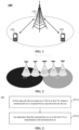
- FIG. 2 exemplarily illustrates an update mode of Soft TAC in a satellite beam moving scenario.
- TA1 and TA2 are areas with fixed geographical locations.
- the satellite covers TA1, then covers part areas of TA1 and TA2 at the same time, and then only covers TA2.
- the satellite may broadcast two TACs (including TAC1 and TAC2) at the same time, so the UE will receive two TACs at the same time, which results in that the UE cannot determine the TA where the UE is located.
- the UE may still initiate subsequent non-access-stratum (NAS) processes, such as a service request or Protocol Data Unit (PDU) session establishment.
- NAS non-access-stratum
- the core network has no corresponding mechanism to deal with this case at present.
- Embodiments of the present disclosure provide a method for indicating a TA where a terminal device is located.
- FIG. 3 is a schematic flowchart of a method 300 for indicating a TA where a terminal device is located according to an embodiment of the present disclosure.
- the method may be applied to the system as illustrated in FIG. 1 or FIG. 2 , but is not limited thereto.
- the method may be applied to a first network device.
- the method includes at least part of the following contents.
- a first network device receives a TAI of a first TA where a terminal device is located from a second network device.
- an indication that the terminal device is in the first TA is transmitted to the terminal device.
- the above operation S320 may include the following operation.
- the first network device In response to determining that the first TA is an area allowing the terminal device to initiate a service and the first TA being not in an RA configured by a core network for the terminal device, the first network device transmits a configuration update instruction to the terminal device.
- the configuration update instruction carries the indication that the terminal device is in the first TA.
- the first network device transmits a rejection message to the terminal device.
- the rejection message carries the indication that the terminal device is in the first TA.
- the network device indicates the TA where the UE is located to the UE, so that the terminal device may know the TA where the terminal device is located, so as to perform normal communication process.
- the first network device may be a core network device, such as an AMF, and the second network device may be a base station.
- the interaction process between the AMF and the base station may include the following operations.
- the first network device being an AMF and the second network device being a base station as an example, the above method is described in detail with following specific embodiments.
- a secure connection is established after the UE is registered, and the base station may know the accurate location of the UE through information such as UE location measurement or Global Navigation Satellite System (GNSS), and may obtain the TA where the UE initiates the NAS process through a mapping relationship between the information and a geographical location of the TA (in this embodiment and the following embodiments, the TA where the LTE is located is called as the first TA). For example, when the terminal device moves from the TA1 to the TA2, the first TA where the UE is currently located is TA2.
- the base station transmits ULI to the AMF, and the ULI carries the TAI of the first TA (i.e. TA2).
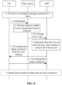
- FIG. 4 is an implementation flowchart of the first embodiment of the present disclosure. The implementation includes the following operations.
- a base station has a capability of determining a first TA where UE is located.
- the difference between the first embodiment and this embodiment is that in this embodiment, the first TA where the UE is located is considered to be a restricted area.
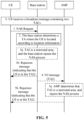
- FIG. 5 is an implementation flowchart of the second embodiment of the present disclosure. The implementation includes the following operations.
- FIG. 6 is a schematic flowchart of a method 600 for determining a TA where a terminal device is located according to an embodiment of the present disclosure.
- the method may be applied to the system illustrated in FIG. 1 or FIG. 2 , but is not limited thereto.
- the method may be applied to a second network device. The method includes at least part of the following contents.
- a second network device determines a first TA where the terminal device is located from at least two TAs corresponding to at least two TAIs for the terminal device.
- the second network device may transmit a TAI of the first TA to a first network device.
- the second network device transmits an N2 message to the first network device.
- the N2 message carries ULI which carries the TAI of the first TA.
- the second network device may be a base station and the first network device may be an AMF.
- the method may further include the following operation.
- the second network device When it is determined that the first TA is the restricted area, the second network device (i.e., the base station) transmits a rejection message to the terminal device.
- the rejection message carries an indication that the terminal device is in the first TA. For example, a dedicated field is provided in the rejection message, and the value of the field is set to the TAI of the first TA, which indicates that the UE is currently in the first TA.
- the above restricted area includes a non-allowed area or a forbidden area.
- the operation of determining the first TA where the terminal device is located may include the following operations.
- the second network device determines a location of the terminal device.
- the second network device determines the first TA where the terminal device is located according to the location.
- the above NAS request may include a service request or a PDU session establishment request, etc.
- FIG. 7 is a schematic flowchart of a method 700 for processing an NAS request according to an embodiment of the present disclosure.
- the method may be applied to the system as illustrated in FIG. 1 or FIG. 2 , but is not limited thereto.
- the method may be applied to an AMF.
- the method includes at least part of the following contents.
- a first network device receives an NAS request of a terminal device and at least two TAIs for the terminal device from a second network device.
- the first network device accepts the NAS request.
- the first network device includes an AMF and the second network device includes a base station.
- the base station has no capability of determining an accurate location of the terminal device. Therefore, all the TAIs (at least two TAIs) for the terminal device are transmitted to the AMF. The first TA where the terminal is located is determined by the AMF.
- the base station may transmit an N2 message to the AMF, and the N2 message carries at least two TAIs for the NAS request of the terminal device.
- the above operation S710 includes the following operations.
- the first network device receives the N2 message from the second network device.
- the N2 message carries the NAS request and ULI which carries two TAIs for the terminal device.
- the base station receives the NAS request from the UE.
- the base station receives an NAS request, such as a PDU session establishment request, transmitted by UE in a connected state.
- the base station receives an NAS request, such as a service request, transmitted by UE in an idle state.
- At least one TA corresponding to at least one TAI is an area allowing the UE to initiate a service. That is, there are the following two cases.
- the TAs corresponding to all TAIs received by the AMF are the areas allowing the UE to initiate the service.
- any TA the UE currently located is an area allowing the UE to initiate the service, so that the AMF accepts the NAS request and continues to perform the NAS process.
- a part of the TAs corresponding to the TAIs received by the AMF is the area allowing the UE to initiate the service, and another part is the restricted area.
- the TA where the UE is currently located may be the area allowing the UE to initiate the service, or may be the restricted area.
- the TA where the UE is currently located may be the area allowing the UE to initiate the service, or may be the restricted area, in both cases, the AMF first considers that the TA where the UE is currently located is the area allowing the UE to initiate the service, accepts the NAS request, and continues to perform the NAS process. After determining that the first TA where the UE is currently located is the restricted area, the AMF releases the corresponding connection.
- the AMF after the AMF receives the NAS request and at least two TAIs, it firstly accepts the NAS request, that is, the above operation S720 is performed.
- the AMF may complete the configuration update of the UE. Further, the AMF may determine the first TA where the UE is located, and the configuration update instruction transmitted by the AMF to the UE carries an indication that the UE is in the first TA.
- the AMF may determine the first TA where the UE is located. Then, in response to determining that the first TA is an area allowing the terminal device to initiate a service and the first TA is not in the RA configured by the core network for the terminal device, the configuration update is performed on the terminal device. In response to determining that the first TA is a restricted area, the AMF releases the corresponding connection.
- the method may further include the following operation.
- the first network device transmits a configuration update instruction to the terminal device in response to the above at least two TAs corresponding to the at least two TAIs being areas allowing the terminal device to initiate the service.
- the method may further include the following operations.
- the first network device determines the first TA where the terminal device is located from the at least two TAs corresponding to the at least two TAIs.
- the first network device transmits a configuration update instruction to the terminal device.
- the configuration update instruction carries an indication that the terminal device is in the first TA.
- This method is applicable to the case that the at least two TAs corresponding to the at least two TAIs received by the AMF are areas allowing the terminal device to initiate the service, and is also applicable to the case that not all of the at least two TAs corresponding to the at least two TAIs are areas allowing the terminal device to initiate the service.
- the method may further include the following operations.
- the first network device determines the first TA where the terminal device is located from the at least two TAs corresponding to the at least two TAIs.
- the first network device transmits an N2 resource release request to the second network device or transmits a connection release request to the terminal device.
- the N2 resource release request carries an indication that the terminal device is in the first TA
- the connection release request carries the indication that the terminal device is in the first TA.
- the AMF transmits the N2 resource release request to the base station, and the AMF transmits the connection release request to the UE.
- the above restricted area includes a non-allowed area or a forbidden area.
- the operation of the first network device determining the first TA where the terminal device is located includes the following operations.
- the first network device performs a location service (LCS) process to determine a location of the terminal device.
- LCS location service
- the first network determines the first TA where the terminal device is located according to the location.
- the UE receives a broadcast message containing two TACs which includes the TA1 and the TA2.
- UE in a connected state initiates an NAS request, such as a PDU session establishment request.
- the base station has no capability of determining an accurate location of the UE. Therefore, the base station transmits both two TAIs (e.g. TA1, TA2) in ULI in an N2 message to an AMF.
- both TAs corresponding to the two TAIs are areas allowing the UE to initiate a service. For example, when the terminal device moves from the TA1 to the TA2, the first TA where the UE is currently located is the TA2.
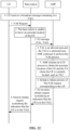
- FIG. 8 is an implementation flowchart of the third embodiment of the present disclosure. The implementation includes the following operations.
- FIG. 9 is an implementation flowchart of the fourth embodiment of the present disclosure. The implementation includes the following operations.
- UE in an idle state initiates an NAS request, such as a service request.
- a base station has no capability of determining an accurate location of the UE. Therefore, the base station transmits both TAIs (e.g. TA1, TA2) in ULI in an N2 message to an AMF.
- both TAs are areas allowing the UE to initiate a service. For example, when the terminal device moves from the TA1 to the TA2, the first TA where the UE is currently located is the TA2.
- FIG. 10 is an implementation flowchart of the fifth embodiment of the present disclosure. The implementation includes the following operations.
- the consideration condition of the present embodiment is the same as that of the fifth embodiment.
- FIG. 11 is an implementation flowchart of the sixth embodiment of the present disclosure. The implementation includes the following operations.
- the above third embodiment to sixth embodiment provide manners for processing a situation in which TAs corresponding to all TAIs in the broadcast message received by the UE are areas allowing the UE to initiate a service, and the UE may be in a connected state or an idle state.
- the AMF performs a configuration update for the UE, and the configuration update instruction may carry an indication that the LTE is in the first TA.
- the following describes manners for processing a situation in which the TAs corresponding to some TAIs in the broadcast message received by the UE are areas allowing the UE to initiate a service.
- the UE in the connection state initiates an NAS request, such as a PDU session establishment request.
- the base station has no capability of determining an accurate location of the UE. Therefore, the base station transmits both two TAIs in ULI in an N2 message to the AMF.
- the TA1 is an area allowing the UE to initiate a service
- the TA2 is a restricted area. For example, when the terminal device moves from the TA1 to the TA2, the first TA where the UE is currently located is the TA2.
- FIG. 12 is an implementation flowchart of the seventh embodiment of the present disclosure. The implementation includes the following operations.
- the UE in an idle state initiates an NAS request, such as a service request.
- the base station has no capability of determining an accurate location of the UE. Therefore, the base station transmits both TAIs (e.g. TA1, TA2) in ULI in an N2 message to the AMF.
- TAIs e.g. TA1, TA2
- the TA1 is an area allowing the UE to initiate a service and the TA2 is a restricted area. For example, when the terminal device moves from TA1 to TA2, the first TA where the UE is currently located is the TA2.
- FIG. 13 is an implementation flowchart of the eighth embodiment of the present disclosure. The implementation includes the following operations.
- the above seventh embodiment and eighth embodiment provide manners for processing a situation in which TAs corresponding to a part of TAIs in the broadcast message received by the UE are areas allowing the UE to initiate a service, and the UE may be in a connected state or an idle state.
- the AMF when receiving the N2 message, the AMF first accepts the NAS request and enables the UE to be in the connected state. Then the AMF initiates the LCS process to determine the TA where the UE is located. If the TA where the UE is located is a restricted area, the AMF releases the corresponding connection, and the release request carries the indication that the UE is in the first TA.
- the above embodiments only take the NAS request such as a service request and PDU session establishment request as example, but the method proposed in the present disclosure is not limited to these two processes.
- the present disclosure takes the broadcast message received by the UE containing TA1 and TA2 as an example, which indicates a case that the UE receives TAs.
- the present application does not limit the number of TAs received by the UE. That is, the number of TAs broadcast by the base station may not be limited to one or two.
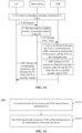
- FIG. 14 is a schematic flowchart of a method 1400 for indicating a TA where a terminal device is located according to an embodiment of the present disclosure.
- the method may be applied to the system as illustrated in FIG. 1 or FIG. 2 , but is not limited to thereto.
- the method may be applied to a second network device.
- the method includes at least part of the following contents.
- a second network device receives an NAS request from a terminal device.
- the second network transmits the NAS request and at least two TAIs for the terminal device to a first network device.
- the second network device includes a base station and the first network device includes an AMF.
- the method further includes the following operations.
- the second network device receives an N2 resource release request from the first network device.
- the N2 resource release request carries an indication that the terminal device is in the first TA.
- the first TA corresponds to a TAI in the at least two TAIs.
- the second network device transmits a session release request to the terminal device.
- the session release request carries then indication that the terminal device is in the first TA.
- the operation of transmitting the NAS request and the at least two TAIs for the terminal device to the first network device includes the following operation.
- the second network device transmits an N2 message to the first network device.
- the N2 message carries the NAS request and ULI, and the ULI carries the at least two TAIs.
- the NAS request includes a service request or a PDU session establishment request.
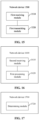
- FIG. 15 is a schematic diagram of a structure of a network device 1500 according to an embodiment of the present disclosure.
- the network device includes a first receiving module 1510 and a first transmitting module 1520.
- the first receiving module is configured to receive a TAI of a first TA where a terminal device is located from a second network device.
- the first transmitting module is configured to transmit an indication that the terminal device is in the first TA to the terminal device.
- the first transmitting module 1510 is configured to transmit a configuration update instruction to the terminal device in response to determining that the first TA is an area allowing the terminal device to initiate a service and the first TA is not in an RA configured by a core network for the terminal device.
- the configuration update instruction carries the indication that the terminal device is in the first TA.
- the first transmitting module 1510 is configured to transmit a rejection message to the terminal device in response to determining that the first TA is a restricted area.
- the rejection message carries the indication that the terminal device is in the first TA.
- the restricted area includes a non-allowed area or a forbidden area.
- the first receiving module 1520 is configured to receive an N2 message from the second network device.
- the N2 message carries ULI
- the ULI carries the TAI of the first TA.
- the network device includes an AMF
- the second network device includes a base station.
- FIG. 16 is a schematic diagram of a structure of a network device 1600 according to an embodiment of the present disclosure.
- the network device includes a second receiving module 1610 and a first processing module 1620.
- the second receiving module is configured to receive an NAS request of a terminal device and at least two TAIs for the terminal device from a second network device.
- the first processing module is configured to accept the NAS request.
- the first processing module 1620 is further configured to transmit a configuration update instruction to the terminal device in response to at least two TAs corresponding to the at least two TAIs being areas allowing the terminal device to initiate a service.
- the first processing module 1620 is further configured to determine a first TA where the terminal device is located from at least two TAs corresponding to the at least two TAIs, and transmit a configuration update instruction to the terminal device in response to the first TA being an area allowing the terminal device to initiate a service and the first TA being not in an RA configured by a core network for the terminal device.
- the configuration update instruction carries an indication that the terminal device is in the first TA.
- the first processing module 1620 is further configured to determine a first TA where the terminal device is located from at least two TAs corresponding to the at least two TAIs, and transmit an N2 resource release request or a connection release request in response to the first TA being a restricted area.
- the N2 resource release request carries an indication that the terminal device is in the first TA
- the connection release request carries an indication that the terminal device is in the first TA.
- the restricted area includes a non-allowed area or a forbidden area.
- the first processing module 1620 is configured to perform an LCS process to determine a location of the terminal device, and determine the first TA where the terminal device is located according to the location.
- the second receiving module 1610 is configured to receive an N2 message from the second network device.
- the N2 message carries the NAS request and ULI, and the ULI carries the at least two TAIs.
- the network device includes an AMF and the second network device includes a base station.
- the NAS request includes a service request or a PDU session establishment request.
- FIG. 17 is a schematic diagram of a structure of a network device 1700 according to an embodiment of the present disclosure.
- the network device 1700 includes a determining module 1720.
- the determining module is configured to determine a first TA where a terminal device is located from at least two TAs corresponding to at least two TAIs for the terminal device in response to receiving an NAS request from the terminal device.
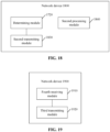
- FIG. 18 is a schematic diagram of a structure of a network device 1800 according to an embodiment of the present disclosure.
- the network device 1800 includes the determining module 1720 and a second transmitting module 1830.
- the second transmitting module is configured to transmit a TAI of the first TA to a first network device.
- the second transmitting module 1830 is configured to transmit an N2 message to the first network device.
- the N2 message carries ULI
- the ULI carries the TAI of the first TA.
- the network device further includes a second processing module 1840 configured to transmit a rejection message to the terminal device in response to determining that the first TA is a restricted area.
- the rejection message carries an indication that the terminal device is in the first TA.
- the restricted area includes a non-allowed area or a forbidden area.
- the determining module 1720 is configured to determine a location of the terminal device, and determine the first TA where the terminal device is located according to the location.
- the NAS request includes a service request or a PDU session establishment request.
- the network device includes a base station.
- the first network device includes an AMF.
- FIG. 19 is a schematic diagram of a structure of a network device 1900 according to an embodiment of the present disclosure.
- the network device 1900 includes a fourth receiving module 1910 and a third transmitting module 1920.
- the fourth receiving module is configured to receive an NAS request from a terminal device.
- the third transmitting module is configured to transmit the NAS request and at least two TAIs for the terminal device to a first network device.
- FIG. 20 is a schematic diagram of a structure of a network device 2000 according to an embodiment of the present disclosure.
- the network device 2000 includes the fourth receiving module 1910, the third transmitting module 1920, a fifth receiving module 2030 and a fourth transmitting module 2040.
- the fifth receiving module is configured to receive an N2 resource release request from the first network device.
- the N2 resource release request carries an indication that the terminal device is in a first TA, and the first TA corresponds to one TAI in the at least two TAIs.
- the fourth transmitting module is configured to transmit a session release request to the terminal device.
- the session release request carries the indication that the terminal device is in the first TA.
- the third transmitting module 1920 is configured to transmit an N2 message to the first network device.
- the N2 message carries the NAS request and ULI, and the ULI carries the at least two TAIs.
- the NAS request includes a service request or a PDU session establishment request.
- the network device includes a base station, and the first network device includes an AMF.
- the functions described by various modules (sub-modules, units or components, etc.) in the network device according to the embodiments of the present disclosure may be implemented by different modules (sub-modules, units or components, etc.) or by a same module (sub-module, unit or component, etc.).
- the first receiving module and the second receiving module may be different modules or the same module, both cases can implement the corresponding functions in the embodiments of the present disclosure.
- the transmitting module and the receiving module in the embodiments of the present disclosure may be implemented by a transceiver of the device, and some or all of the remaining modules may be implemented by a processor of the device.
- FIG. 21 is a schematic diagram of a structure of a communication device 2100 according to an embodiment of the present disclosure.
- the communication device 2100 illustrated in FIG. 21 includes a processor 2110 configured to invoke and run a computer program from a memory to implement the methods in the embodiments of the present disclosure.
- the communication device 2100 may also include a memory 2120.
- the processor 2110 may be configured to invoke and run a computer program from the memory 2120 to implement the methods in the embodiments of the present disclosure.
- the memory 2120 may be a separate device independent of the processor 2110 or may be integrated in the processor 2110.
- the communication device 2100 may further include a transceiver 2130, and the processor 2110 may control the transceiver 2130 to communicate with other devices, and in particular to transmit information or data to other devices or to receive information or data transmitted by other devices.
- the processor 2110 may control the transceiver 2130 to communicate with other devices, and in particular to transmit information or data to other devices or to receive information or data transmitted by other devices.
- the transceiver 2130 may include a transmitter and a receiver.
- the transceiver 2130 may further include an antenna, and the number of antennas may be one or more.
- the communication device 2100 may be a terminal device of the embodiments of the present disclosure, and the communication device 2100 may implement corresponding processes implemented by the terminal device in the respective methods of the embodiments of the present disclosure, which will not be elaborated herein for the sake of brevity.
- the communication device 2100 may be a network device of embodiments of the present disclosure, and the communication device 2100 may implement corresponding processes implemented by the network device in the respective methods of the embodiments of the present disclosure, which will not be elaborated herein for the sake of brevity.
- FIG. 22 is a schematic diagram of a structure of a chip 2200 according to an embodiment of the present disclosure.
- the chip 2200 illustrated in FIG. 22 includes a processor 2210 configured to invoke and run a computer program from a memory to implement the methods in embodiments of the present disclosure.
- the chip 2200 may further include a memory 2220.
- the processor 2210 may invoke and run a computer program from the memory 2220 to implement the methods in embodiments of the present disclosure.
- the memory 2220 may be a separate device independent of the processor 2210 or may be integrated in the processor 2210.
- the chip 2200 may further include an input interface 2230.
- the processor 2210 may control the input interface 2230 to communicate with other devices or chips, in particular, to obtain information or data transmitted by other devices or chips.
- the chip 2200 may further include an output interface 2240.
- the processor 2210 may control the output interface 2240 to communicate with other devices or chips, in particular, to output information or data to other devices or chips.
- the chip may be applied to the terminal device in the embodiments of the present disclosure, and the chip may implement corresponding processes implemented by the terminal device in the respective methods of the embodiments of the present disclosure, which will not be elaborated herein for the sake of brevity.
- the chip may be applied to the network device in the embodiments of the present disclosure, and the chip may implement the corresponding processes implemented by the network device in the respective methods of the embodiments of the present disclosure, which will not be elaborated here for the sake of brevity.
- the chip in embodiments of the present disclosure may also be referred to as a system level chip, a system chip, a chip system or a system-on-chip or the like.
- the processor mentioned above may be a general purpose processor, a digital signal processor (DSP), a field programmable gate array (FPGA), an application specific integrated circuit (ASIC), or other programmable logic devices, transistor logic devices, discrete hardware components, and the like.
- DSP digital signal processor
- FPGA field programmable gate array
- ASIC application specific integrated circuit
- the general purpose processor mentioned above may be a microprocessor or any conventional processor or the like.
- the memory mentioned above may be a volatile memory or a non-volatile memory or may include both a volatile memory and a non-volatile memory.
- the non-volatile memory may be a read-only memory (ROM), a programmable ROM (PROM), an erasable PROM (EPROM), an electrically EPROM (EEPROM) or a flash memory.
- the volatile memory may be a random access memory (RAM).
- the memory described above is for exemplary but not limited description, and, for example, the memory in embodiments of the present disclosure may also be a static RAM (SRAM), a dynamic RAM (DRAM), a synchronous DRAM (SDRAM), a double data rate SDRAM (DDR SDRAM), an enhanced SDRAM (ESDRAM), a synchronous link DRAM (SLDRAM), a Direct Rambus RAM (DR RAM), etc. That is, the memory in embodiments of the present disclosure is intended to include but not limited to these and any other suitable types of memory.
- SRAM static RAM
- DRAM dynamic RAM
- SDRAM synchronous DRAM
- DDR SDRAM double data rate SDRAM
- ESDRAM enhanced SDRAM
- SLDRAM synchronous link DRAM
- DR RAM Direct Rambus RAM
- the above-described embodiments may be implemented in whole or in part by software, hardware, firmware or any combination thereof.
- software When implemented in software, it may be implemented in whole or in part in the form of a computer program product.
- the computer program product includes one or more computer instructions.
- the computer may be a general purpose computer, a special purpose computer, a computer network, or other programmable device.
- the computer instructions may be stored in a computer-readable storage medium, or be transmitted from a computer-readable storage medium to another computer-readable storage medium.
- the computer instructions may be transmitted from a Web site, computer, server, or data center to another Web site, computer, server, or data center via wired (e.g. a Coaxial cable, optical fiber, Digital Subscriber Line (DSL)) or wireless (e.g. Infrared, wireless, microwave, etc.).
- the computer-readable storage medium may be any usable medium accessible to and stored by a computer or a data storage device such as a server, data center, etc. integrate with one or more usable media.
- the usable media may be a magnetic media (e.g. Floppy disk, hard disk, magnetic tape), optical media (e.g. DVD), or semiconductor media (e.g. Solid State Disk (SSD)), etc.
Landscapes
- Engineering & Computer Science (AREA)
- Computer Networks & Wireless Communication (AREA)
- Signal Processing (AREA)
- Databases & Information Systems (AREA)
- Computer Security & Cryptography (AREA)
- Mobile Radio Communication Systems (AREA)
Abstract
Description
- The present application relates to the field of communications, and more particularly, to a method for indicating a tracking area where a terminal device is located and a network device.
- In a satellite network, such as in a Low-Earth Orbit (LEO), a satellite moves relative to the ground, and beams transmitted by the satellite also move relative to the ground. In a case that a location of a tracking area (TA) is fixed, as the satellite moves relative to the ground, the satellite may firstly covers only one TA, then covers part areas of at least two TAs at the same time, and then covers only another TA. In an update mode of Soft Tracking Area Code (Soft TAC), when the satellite covers at least two TAs at the same time, it may broadcast the TACs corresponding to these TAs simultaneously, which results in the situation that the terminal device receives at least two TACs at the same time. In such situation, the terminal device may not know the TA where the terminal device is located, which affects a normal communication process.
- Embodiments of the present disclosure provide a method for indicating a TA where a terminal device is located and a network device, which can enable the terminal device to determine the TA where the terminal device is located and reduce improper operations on a communication process.
- An embodiment of the present disclosure provides a method for indicating a TA where a terminal device is located. The method is applied to a first network device. The method includes the following operations.
- The first network device receives a tracking area identity (TAI) of a first TA where the terminal device is located from a second network device.
- The first network device transmits an indication that the terminal device is in the first TA to the terminal device.
- An embodiment of the present disclosure provides a method for processing a Non-access stratum (NAS) request. The method is applied to a first network device. The method includes the following operations.
- The first network device receives an NAS request of a terminal device and at least two TAIs for the terminal device from a second network device.
- The first network device accepts the NAS request.
- An embodiment of the present disclosure provides a method for determining a TA where a terminal device is located. The method is applied to a second network device. The method includes the following operation.
- In response to receiving an NAS request from the terminal device, the second network device determines a first TA where the terminal device is located from at least two TAs corresponding to at least two TAIs for the terminal device.
- An embodiment of the present disclosure provides a method for indicating a TA where the terminal device is located. The method is applied to the second network device. The method includes the following operations.
- The second network device receives an NAS request from the terminal device.
- The second network device transmits the NAS request and at least two TAIs for the terminal device to a first network device.
- An embodiment of the present disclosure provides a network device. The network device includes a first receiving module and a first transmitting module.
- The first receiving module is configured to receive a TAI of a first TA where a terminal device is located from a second network device.
- The first transmitting module is configured to transmit an indication that the terminal device is in the first TA to the terminal device.
- An embodiment of the present disclosure further provides a network device. The network device includes a second receiving module and a first processing module.
- The second receiving module is configured to receive an NAS request of a terminal device and at least two TAIs for the terminal device from a second network device.
- The first processing module is configured to accept the NAS request.
- An embodiment of the present disclosure further provides a network device. The network device includes a determining module.
- The determining module is configured to: determine a first TA where a terminal device is located from at least two TAs corresponding to at least two TAIs for the terminal device in response to receiving an NAS request from the terminal device.
- An embodiment of the present disclosure further provides a network device. The network device includes a fourth receiving module and a third transmitting module.
- The fourth receiving module is configured to receive an NAS request from a terminal device.
- The third transmitting module is configured to transmit the NAS request and at least two TAIs for the terminal device to a first network device.
- An embodiment of the present disclosure further provides a network device. The network device includes a processor, a memory configured to store a computer program and a transceiver. The processor is configured to invoke and run the computer program stored in the memory and control the transceiver to perform the method as described in any one of the above.
- An embodiment of the present disclosure further provides a chip. The chip includes a processor configured to invoke and run a computer program from a memory to cause a device mounted with the chip to perform the method as described in any one of the above.
- An embodiment of the present disclosure further provides a computer-readable storage medium configured to store a computer program that causes a computer to perform the method as described in any one of the above.
- An embodiment of the present disclosure further provides a computer program product including computer program instructions that cause a computer to perform the method as described in any one of the above.
- An embodiment of the present disclosure further provides a computer program causing a computer to perform the method as described in any one of the above.
- According to the embodiments of the present disclosure, a network device indicates a TA where UE is located to the UE, so that the terminal device can determine the TA where the terminal device is located, so as to perform a normal communication process.
-
-
FIG. 1 is a schematic diagram of an application scenario of embodiment of the present disclosure. -
FIG. 2 is a schematic diagram of an update mode of Soft TAC in a satellite beam moving scenario. -
FIG. 3 is a schematic flowchart of amethod 300 for indicating a TA where a terminal device is located according to an embodiment of the present disclosure. -
FIG. 4 is an implementation flowchart of a first embodiment of the present disclosure. -
FIG. 5 is an implementation flowchart of a second embodiment of the present disclosure. -
FIG. 6 is a schematic flow diagram of amethod 600 for determining a TA where a terminal device is located according to an embodiment of the present disclosure. -
FIG. 7 is a schematic flowchart of a method for processing anNAS request 700 according to an embodiment of the present disclosure. -
FIG. 8 is an implementation flowchart of a third embodiment of the present disclosure. -
FIG. 9 is an implementation flowchart of a fourth embodiment of the present disclosure. -
FIG. 10 is an implementation flowchart of a fifth embodiment of the present disclosure. -
FIG. 11 is an implementation flowchart of a sixth embodiment of the present disclosure. -
FIG. 12 is an implementation flowchart of a seventh embodiment of the present disclosure. -
FIG. 13 is an implementation flowchart of an eighth embodiment of the present disclosure. -
FIG. 14 is a schematic flowchart of amethod 1400 for indicating a TA where a terminal device is located according to an embodiment of the present disclosure. -
FIG. 15 is a schematic diagram of a structure of anetwork device 1500 according to an embodiment of the present disclosure. -
FIG. 16 is a schematic diagram of a structure of anetwork device 1600 according to an embodiment of the present disclosure. -
FIG. 17 is a schematic diagram of a structure of anetwork device 1700 according to an embodiment of the present disclosure. -
FIG. 18 is a schematic diagram of a structure of anetwork device 1800 according to an embodiment of the present disclosure. -
FIG. 19 is a schematic diagram of a structure of anetwork device 1900 according to an embodiment of the present disclosure. -
FIG. 20 is a schematic diagram of a structure of anetwork device 2000 according to an embodiment of the present disclosure. -
FIG. 21 is a schematic diagram of a structure of acommunication device 2100 according to an embodiment of the present disclosure. -
FIG. 22 is a schematic diagram of a structure of achip 2200 according to an embodiment of the present disclosure. - The technical solutions in the embodiments of the present disclosure will be described below with reference to the drawings in the embodiments of the present disclosure.
- It should be noted that the terms "first", "second", etc. in the description and claims of embodiments of the present disclosure and the above drawings are used to distinguish similar objects and are not necessarily used to describe a specific order or priority. The objects described in the "first" and "second" at the same time can be the same or different.
- The technical solutions of the embodiments of the present disclosure may be applied to various communication systems, such as, Global System of Mobile communication (GSM) system, Code Division Multiple Access (CDMA) system, Wideband Code Division Multiple Access (WCDMA) system, General Packet Radio Service (GPRS), Long Term Evolution (LTE) system, Advanced long term evolution (LTE-A) system, New Radio (NR) system, evolution system of NR system, and LTE-based access to unlicensed spectrum (LTE-U) system, NR-based access to unlicensed spectrum (NR-U) system, Universal Mobile Telecommunication System (UMTS), Wireless Local Area Networks (WLAN), Wireless Fidelity (WiFi), 5th-Generation (5G) system or other communication systems.
- In general, conventional communication systems support a limited number of connections and are easy to be implemented. However, with the development of communication technology, mobile communication systems will not only support conventional communication, but also support, for example, Device to Device (D2D) communication, Machine to Machine (M2M) communication, Machine Type Communication (MTC), Vehicle to Vehicle (V2V) communication, etc. Embodiments of the present disclosure may also be applied to these communication systems.
- Alternatively, the communication system in the embodiments of the present disclosure may be applied to a Carrier Aggregation (CA) scenario, a Dual Connectivity (DC) scenario, and a Standalone (SA) network distribution scenario.
- Embodiments of the present disclosure do not limit spectrums applied. For example, embodiments of the present disclosure may be applied to a licensed spectrum or an unlicensed spectrum.
- Various embodiments of the present disclosure are described in combination with a network device and a terminal device. The terminal device may also be referred to as User Equipment (UE), an access terminal, a subscriber unit, a subscriber station, a mobile station, a mobile stage, a remote station, a remote terminal, a mobile device, a user terminal, a terminal, a wireless communication device, a user agent or a user device, etc. The terminal device may be a STATION (ST) in a WLAN, a cellular telephone, a cordless telephone, a Session Initiation Protocol (SIP) telephone, a Wireless Local Loop (WLL) station, a Personal Digital Assistant (PDA) device, a handheld device and a computing device having a wireless communication function or other processing device connected to a wireless modem, a vehicle-mounted device, a wearable device, and a terminal device in a next generation communication system, such as a terminal device in an NR network or in a future evolved Public Land Mobile Network (PLMN) network.
- By way of example and not limitation, in the embodiments of the present disclosure, the terminal device may also be a wearable device. The wearable device may also be called as a wearable intelligent device, which is a general name of wearable devices developed by applying wearable technology to intelligently design daily wears, such as glasses, gloves, watches, clothing and shoes. The wearable device is a portable device that is worn directly on the body or integrated into the clothes or accessories of user. The wearable device is not only a kind of a hardware device, but may also realize powerful functions through software support, data interaction and cloud interaction. Generalized wearable smart device has features of full functions, large size and implementation of complete or partial functions without relying on smart phones, such as smart watches or smart glasses, and of only focusing on certain application functions, being used in conjunction with other devices such as smart phones, such as various smart bracelets and smart jewelry for monitoring physical signs.
- The network device may be a device for communicating with a mobile device. The network device may be an Access Point (AP) in a WLAN, a Base Transceiver Station (BTS) in a GSM or CDMA, a base station (NodeB, NB) in a WCDMA, an Evolutional Node B (eNB or eNodeB) in an LTE, a relay station or an AP, a vehicle-mounted device, a wearable device, a network device in a NR network (gNB) or a network device in a future evolved PLMN network, etc.
- In the embodiments of the present disclosure, the network device provides services for a cell, and the terminal device communicates with the network device through transmission resources (e.g. frequency domain resources, or spectrum resources) used by the cell. The cell may be a cell corresponding to the network device (e.g. base station), and the cell may be covered by a macro base station or a base station corresponding to a Small cell. The Small cell may include a Metro cell, a Micro cell, a Pico cell, a Femto cell, etc. These Small cells have the characteristics of small coverage and low transmission power, and are suitable for providing high-speed data transmission services.
-
FIG. 1 exemplarily illustrates onenetwork device 110 and twoterminal devices 120. Alternatively, thewireless communication system 100 may include a plurality ofnetwork devices 110, and a coverage of eachnetwork device 110 may include other numbers ofterminal devices 120, which are not limited in the embodiments of the present disclosure. The embodiments of the present disclosure may be applied to oneterminal device 120 and onenetwork device 110, and may also be applied to oneterminal device 120 and anotherterminal device 120. - Alternatively, the
wireless communication system 100 may also include other network entities, such as a Mobility Management Entity (MME), an Access and Mobility Management Function (AMF), etc. Embodiments of the present disclosure are not limited thereto. - It should be understood that the terms "system" and "network" are often used interchangeably herein. In the present disclosure, the term "and/or" is merely used for describing an association relationship of related objects, indicates that there may be three relationships, for example, A and/or B, which means that there are three cases: A exists alone, both A and B exist, and B exists alone. In addition, the character "f" in the present disclosure generally indicates that there is "or" relationship between the related objects.
- It should be understood that the "indicating" mentioned in embodiments of the present disclosure may be a direct indication, may be an indirect indication, or may be represent an association. For example, the expression that A indicates B may mean that A directly indicates B, for example, B may be obtained through A. The expression may also mean that A indirectly indicates B, for example, A indicates C, and B may be obtained by C. The expression may also indicate that there is an association relationship between A and B.
- In the description of embodiments of the present disclosure, the term "correspondence" may mean that there is a direct correspondence or an indirect correspondence between the two objects, may also mean that there is an association relationship between the two objects, may also be a relationship of indicating and being indicated, configuring and being configured, etc.
- In order to facilitate understanding of the technical solutions of the embodiments of the present disclosure, the related technologies of the embodiments of the present disclosure are described in the following. The following related technologies, as an alternative solution, may be arbitrarily combined with the technical solutions of the embodiments of the present disclosure, all of which fall within the protection scope of the embodiments of the present disclosure.
-
FIG. 2 exemplarily illustrates an update mode of Soft TAC in a satellite beam moving scenario. As illustrated inFIG. 2 , TA1 and TA2 are areas with fixed geographical locations. During movement of the satellite, the satellite covers TA1, then covers part areas of TA1 and TA2 at the same time, and then only covers TA2. In the Soft TAC mode, when the satellite covers both TA1 and TA2, the satellite may broadcast two TACs (including TAC1 and TAC2) at the same time, so the UE will receive two TACs at the same time, which results in that the UE cannot determine the TA where the UE is located. For example, in a case where the TA1 is in a registration area (RA) of the UE and the TA2 is not in the RA of the UE, since the UE always receives two TACs when the UE moves from TA1 to TA2, the UE cannot judge whether it is in TA1 or TA2 currently. After the UE registered in TA1 moves to TA2, the UE may still initiate subsequent non-access-stratum (NAS) processes, such as a service request or Protocol Data Unit (PDU) session establishment. In addition, if user location information (ULI) transmitted by the base station to a core network carries two TAIs (each TAI corresponds to one TAC, and TAI contains the corresponding TAC and the indication of the country where it is located), the core network has no corresponding mechanism to deal with this case at present. - Embodiments of the present disclosure provide a method for indicating a TA where a terminal device is located.
FIG. 3 is a schematic flowchart of amethod 300 for indicating a TA where a terminal device is located according to an embodiment of the present disclosure. Alternatively, the method may be applied to the system as illustrated inFIG. 1 or FIG. 2 , but is not limited thereto. The method may be applied to a first network device. The method includes at least part of the following contents. - In operation S310, a first network device receives a TAI of a first TA where a terminal device is located from a second network device.
- In operation S320, an indication that the terminal device is in the first TA is transmitted to the terminal device.
- The above operation S320 may include the following operation.
- In response to determining that the first TA is an area allowing the terminal device to initiate a service and the first TA being not in an RA configured by a core network for the terminal device, the first network device transmits a configuration update instruction to the terminal device. The configuration update instruction carries the indication that the terminal device is in the first TA.
- Alternatively, in response to determining that the first TA is a restricted area, the first network device transmits a rejection message to the terminal device. The rejection message carries the indication that the terminal device is in the first TA.
- Through performing the above process, the network device indicates the TA where the UE is located to the UE, so that the terminal device may know the TA where the terminal device is located, so as to perform normal communication process.
- The first network device may be a core network device, such as an AMF, and the second network device may be a base station.
- Taking the first network device being the AMF and the second network device being the base station as an example, in the above method, the interaction process between the AMF and the base station may include the following operations.
- 1. The base station receives an NAS request from the terminal device, determines the first TA where the terminal device is located, and transmits the TAI of the first TA to the AMF.
- 2. If the first TA is the area allowing the terminal device to initiate a service and the first TA is not in the RA configured by the core network for the terminal device, the AMF adds the first TA to the RA and feeds back the configuration update instruction to the terminal device. The configuration update instruction carries the indication that the terminal device is in the first TA.
- 3. If the first TA is the restricted area, the AMF feeds back the rejection message to the terminal device. The rejection message carries the indication that the terminal device is in the first TA.
- Taking the first network device being an AMF and the second network device being a base station as an example, the above method is described in detail with following specific embodiments.
- In this embodiment, a secure connection is established after the UE is registered, and the base station may know the accurate location of the UE through information such as UE location measurement or Global Navigation Satellite System (GNSS), and may obtain the TA where the UE initiates the NAS process through a mapping relationship between the information and a geographical location of the TA (in this embodiment and the following embodiments, the TA where the LTE is located is called as the first TA). For example, when the terminal device moves from the TA1 to the TA2, the first TA where the UE is currently located is TA2. The base station transmits ULI to the AMF, and the ULI carries the TAI of the first TA (i.e. TA2).
-
FIG. 4 is an implementation flowchart of the first embodiment of the present disclosure. The implementation includes the following operations. - 1. The UE transmits an NAS message, such as a service request or PDU session establishment request, to a base station.
- 2. The base station determines the first TA where the UE is currently located according to location information of the UE.
- 3. The base station transmits an N2 message to the AMF. The N2 message carries ULI which carries a TAI of the first TA (such as TA2) where the UE is currently located.
- 4. The AMF determines whether TA2 is an area allowing the terminal device to initiate a service (Allowed Area), and determines whether TA2 is in the RA configured by a core network for the terminal device. In this embodiment, considering that TA2 is an area allowing the UE to initiate the service and TA2 is not in the RA of the UE, TA2 may be added to the RA of the UE and the subsequent NAS process may be continued.
- 5. The AMF transmits a configuration update instruction to the UE. The configuration update instruction includes an updated TAI list, and the TAI list contains the TA2. The configuration update instruction carries an indication that the UE is in TA2. For example, a dedicated field is provided in the configuration update instruction and the value of the field is set to TA2, which indicates that the UE is currently in the TA2. Alternatively, if the TA2 corresponds to new slice information, the new slice information is contained in the configuration update instruction transmitted to the UE.
- 6. After receiving the configuration update instruction, UE needs to response and transmits a configuration update completion message to the AMF.
- 7. Since the new slice information provided by the AMF has no impact on an existing slice connection, the AMF does not need to release an NAS signaling connection after receiving the response, and the UE does not need to perform a registration process immediately.
- Similar to the first embodiment, a base station has a capability of determining a first TA where UE is located. The difference between the first embodiment and this embodiment is that in this embodiment, the first TA where the UE is located is considered to be a restricted area.
-
FIG. 5 is an implementation flowchart of the second embodiment of the present disclosure. The implementation includes the following operations. - 1. The UE transmits an NAS message, such as a service request or a PDU session establishment request, to the base station.
- 2. The base station determines the first TA (for example, TA2) where the UE is currently located according to location information of the UE. Then, if the base station has the capability of determining whether the TA2 is a restricted area, the process proceeds to
operation 3a andoperation 3b. If the base station has no capability of determining whether the TA2 is the restricted area, then the process proceeds tooperation 4, theoperation 5a and theoperation 5b. - 3a. The base station determines that the TA2 is the restricted area through a mobility restriction list transmitted by a core network previously. The restricted area includes a non-allowed area or a forbidden area.
- 3b. The base station transmits a rejection message to the UE, the rejection message carries an indication that the UE is in the TA2. For example, a dedicated field is provided in the rejection message, and the value of the field is set to TA2, which indicates that the UE is currently in the TA2.
- 4. If the base station is unable to determine whether the TA2 is the restricted area, the base station transmits an N2 message to the AMF. The N2 message carries ULI which carries a TAI of the first TA (i.e., TA2) where the UE is currently located.
- 5a. The AMF determines that the TA2 is a restricted area which includes a non-allowed area or a forbidden area, and then rejects the NAS process.
- 5b. The AMF transmits a rejection message to the UE, and the rejection message carries an indication that the UE is in the TA2. For example, a dedicated field is provided in the rejection message, and the value of the field is set to TA2, which indicates that the UE is currently in the TA2.
- With reference to the first and second embodiments described above, the present disclosure provides a method for determining a TA where a terminal device is located.
FIG. 6 is a schematic flowchart of amethod 600 for determining a TA where a terminal device is located according to an embodiment of the present disclosure. Alternatively, the method may be applied to the system illustrated inFIG. 1 or FIG. 2 , but is not limited thereto. The method may be applied to a second network device. The method includes at least part of the following contents. - In operation S610, in response to receiving an NAS request from a terminal device, a second network device determines a first TA where the terminal device is located from at least two TAs corresponding to at least two TAIs for the terminal device.
- Further, the second network device may transmit a TAI of the first TA to a first network device.
- For example, the second network device transmits an N2 message to the first network device. The N2 message carries ULI which carries the TAI of the first TA.
- Alternatively, the second network device may be a base station and the first network device may be an AMF.
- If the base station has a capability of determining whether the first TA is a restricted area, the method may further include the following operation.
- When it is determined that the first TA is the restricted area, the second network device (i.e., the base station) transmits a rejection message to the terminal device. The rejection message carries an indication that the terminal device is in the first TA. For example, a dedicated field is provided in the rejection message, and the value of the field is set to the TAI of the first TA, which indicates that the UE is currently in the first TA.
- Alternatively, the above restricted area includes a non-allowed area or a forbidden area.
- Alternatively, the operation of determining the first TA where the terminal device is located may include the following operations.
- The second network device determines a location of the terminal device.
- The second network device determines the first TA where the terminal device is located according to the location.
- The above NAS request may include a service request or a PDU session establishment request, etc.
- Embodiments of the present disclosure provide a method for processing an NAS request.
FIG. 7 is a schematic flowchart of amethod 700 for processing an NAS request according to an embodiment of the present disclosure. Alternatively, the method may be applied to the system as illustrated inFIG. 1 or FIG. 2 , but is not limited thereto. The method may be applied to an AMF. The method includes at least part of the following contents. - In operation S710, a first network device receives an NAS request of a terminal device and at least two TAIs for the terminal device from a second network device.
- In operation S720, the first network device accepts the NAS request.
- Alternatively, the first network device includes an AMF and the second network device includes a base station.
- In this case, the base station has no capability of determining an accurate location of the terminal device. Therefore, all the TAIs (at least two TAIs) for the terminal device are transmitted to the AMF. The first TA where the terminal is located is determined by the AMF.
- The base station may transmit an N2 message to the AMF, and the N2 message carries at least two TAIs for the NAS request of the terminal device. For example, the above operation S710 includes the following operations. The first network device receives the N2 message from the second network device. The N2 message carries the NAS request and ULI which carries two TAIs for the terminal device.
- Before the operation S710, the base station receives the NAS request from the UE. For example, the base station receives an NAS request, such as a PDU session establishment request, transmitted by UE in a connected state. Alternatively, the base station receives an NAS request, such as a service request, transmitted by UE in an idle state.
- In the TAIs received by AMF, at least one TA corresponding to at least one TAI is an area allowing the UE to initiate a service. That is, there are the following two cases.
- First case: the TAs corresponding to all TAIs received by the AMF are the areas allowing the UE to initiate the service. In this case, any TA the UE currently located is an area allowing the UE to initiate the service, so that the AMF accepts the NAS request and continues to perform the NAS process.
- Second case: a part of the TAs corresponding to the TAIs received by the AMF is the area allowing the UE to initiate the service, and another part is the restricted area. In this case, the TA where the UE is currently located may be the area allowing the UE to initiate the service, or may be the restricted area. the TA where the UE is currently located may be the area allowing the UE to initiate the service, or may be the restricted area, in both cases, the AMF first considers that the TA where the UE is currently located is the area allowing the UE to initiate the service, accepts the NAS request, and continues to perform the NAS process. After determining that the first TA where the UE is currently located is the restricted area, the AMF releases the corresponding connection.
- As can be seen from the above description, in any of above cases, after the AMF receives the NAS request and at least two TAIs, it firstly accepts the NAS request, that is, the above operation S720 is performed.
- If all TAs corresponding to the TAIs received by the AMF are areas allowing the terminal device to initiate the service, the AMF may complete the configuration update of the UE. Further, the AMF may determine the first TA where the UE is located, and the configuration update instruction transmitted by the AMF to the UE carries an indication that the UE is in the first TA.
- If not all the TAs corresponding to the TAIs received by the AMF are areas allowing the terminal device to initiate the service, the AMF may determine the first TA where the UE is located. Then, in response to determining that the first TA is an area allowing the terminal device to initiate a service and the first TA is not in the RA configured by the core network for the terminal device, the configuration update is performed on the terminal device. In response to determining that the first TA is a restricted area, the AMF releases the corresponding connection.
- Therefore, after the above operation S720, the method may further include the following operation.
- The first network device transmits a configuration update instruction to the terminal device in response to the above at least two TAs corresponding to the at least two TAIs being areas allowing the terminal device to initiate the service.
- Alternatively, after the above operation S720, the method may further include the following operations.
- The first network device determines the first TA where the terminal device is located from the at least two TAs corresponding to the at least two TAIs.
- In the case that the first TA is an area allowing the terminal device to initiate a service and the first TA is not in the RA configured by the core network for the terminal device, the first network device transmits a configuration update instruction to the terminal device. The configuration update instruction carries an indication that the terminal device is in the first TA.
- This method is applicable to the case that the at least two TAs corresponding to the at least two TAIs received by the AMF are areas allowing the terminal device to initiate the service, and is also applicable to the case that not all of the at least two TAs corresponding to the at least two TAIs are areas allowing the terminal device to initiate the service.
- Alternatively, after the above operation S720, the method may further include the following operations.
- The first network device determines the first TA where the terminal device is located from the at least two TAs corresponding to the at least two TAIs.
- In response to the first TA being a restricted area, the first network device transmits an N2 resource release request to the second network device or transmits a connection release request to the terminal device. The N2 resource release request carries an indication that the terminal device is in the first TA, alternatively, the connection release request carries the indication that the terminal device is in the first TA. For example, the AMF transmits the N2 resource release request to the base station, and the AMF transmits the connection release request to the UE.
- Alternatively, the above restricted area includes a non-allowed area or a forbidden area.
- In some embodiments, in the above process, the operation of the first network device determining the first TA where the terminal device is located includes the following operations.
- The first network device performs a location service (LCS) process to determine a location of the terminal device.
- The first network determines the first TA where the terminal device is located according to the location.
- Taking the first network device being the AMF and the second network device being the base station as an example, the above method is described in detail with specific embodiments. In the following embodiment, it is considered that the UE receives a broadcast message containing two TACs which includes the TA1 and the TA2.
- In this embodiment, UE in a connected state initiates an NAS request, such as a PDU session establishment request. The base station has no capability of determining an accurate location of the UE. Therefore, the base station transmits both two TAIs (e.g. TA1, TA2) in ULI in an N2 message to an AMF. In this embodiment, it is considered that both TAs corresponding to the two TAIs are areas allowing the UE to initiate a service. For example, when the terminal device moves from the TA1 to the TA2, the first TA where the UE is currently located is the TA2.
-
FIG. 8 is an implementation flowchart of the third embodiment of the present disclosure. The implementation includes the following operations. - 1. The UE in the connection state initiates an NAS request message, such as a PDU session establishment request.
- 2-3. The base station has no capability of knowing an accurate location of the UE. The base station transmits an N2 message to the AMF. The N2 message carries ULI, and the ULI carries the NAS request and two TAIs for the UE, i.e., TA1 and TA2.
- 4. The AMF receives the N2 message, accepts the NAS request, and continues to perform the NAS process. The AMF determines whether the two TAs are areas allowing the UE to initiate a service. Since it is considered in this embodiment that both TAs are areas allowing the UE to initiate the service, in this operation, the determination result is that both TAs are areas allowing the UE to initiate the service.
- 5. The AMF transmits a configuration update instruction to the UE. The configuration update instruction includes an updated TAI list, and the TAI list contains the TA2. Alternatively, if the TA2 corresponds to new slice information, the new slice information is contained in the configuration update instruction, and the configuration update instruction is transmitted to the UE.
- 6. After receiving the configuration update instruction, the UE needs to response and transmits a configuration update completion message to the AMF.
- 7. Since the new slice information provided by the AMF has no impact on an existing slice connection, the AMF does not need to release an NAS signaling connection after receiving the response, and the UE does not need to perform a registration process immediately.
- The consideration condition of this embodiment is the same as that of the third embodiment.
-
FIG. 9 is an implementation flowchart of the fourth embodiment of the present disclosure. The implementation includes the following operations. - 1. The UE in connected state initiates an NAS request message, such as a PDU session establishment request.
- 2-3. The base station has no capability of knowing an accurate location of the UE. The base station transmits an N2 message to the AMF. The N2 message carries ULI, and the ULI carries the NAS request and two TAIs for the UE, i.e., TA1 and TA2.
- 4. The AMF receives the N2 message, accepts the NAS request, and continues to perform the NAS process. The AMF determines whether the two TAs are areas allowing the UE to initiate a service. Since it is considered in this embodiment that both TAs are areas allowing the UE to initiate the service, in this operation, the determination result is that both TAs are areas allowing the UE to initiate the service.
- 5. The AMF initiates an LCS process to obtain the accurate location information of the UE, and determines an area where the UE is currently located, such as TA2, according to the location of the UE.
- 6. The AMF transmits a configuration update instruction to the UE. The configuration update instruction includes an updated TAI list. The TAI list contains TA2 and an indication that the UE is in the TA2. For example, a dedicated field is provided in the configuration update instruction, and the value of the field is set to TA2, which indicates that the UE is currently in the TA2. Alternatively, if the TA2 corresponds to new slice information, the new slice information is contained in the configuration update instruction, and the configuration update instruction is transmitted to the UE.
- 7. After receiving the configuration update instruction, the UE needs to response and transmits a configuration update completion message to the AMF.
- 8. Since the new slice information provided by the AMF has no impact on an existing slice connection, the AMF does not need to release an NAS signaling connection after receiving the response, and the UE does not need to perform a registration process immediately.
- In this embodiment, UE in an idle state initiates an NAS request, such as a service request. A base station has no capability of determining an accurate location of the UE. Therefore, the base station transmits both TAIs (e.g. TA1, TA2) in ULI in an N2 message to an AMF. In this embodiment, it is considered that both TAs are areas allowing the UE to initiate a service. For example, when the terminal device moves from the TA1 to the TA2, the first TA where the UE is currently located is the TA2.
-
FIG. 10 is an implementation flowchart of the fifth embodiment of the present disclosure. The implementation includes the following operations. - 1. The UE in the idle state initiates an NAS request message, such as a service request.
- 2-3. The base station has no capability of knowing an accurate location of the UE. The base station transmits an N2 message to the AMF. The N2 message carries ULI, and the ULI carries the NAS request and two TAIs for the UE, i.e., TA1 and TA2.
- 4. The AMF receives the N2 message, accepts the NAS request, continues to perform the NAS process and enables the UE to be in a connected state. The AMF determines whether the two TAs are areas allowing the UE to initiate a service. Since it is considered in this embodiment that both TAs are areas allowing the UE to initiate the service, in this operation, the determination result is that both TAs are areas allowing the UE to initiate the service.
- 5. The AMF transmits a configuration update instruction to the UE. The configuration update instruction includes an updated TAI list, and the TAI list contains the TA2. Alternatively, if the TA2 corresponds to new slice information, the new slice information is contained in the configuration update instruction which is transmitted to the UE.
- 6. After receiving the configuration update instruction, UE needs to response and transmits a configuration update completion message to the AMF.
- 7. Since the new slice information provided by the AMF has no impact on an existing slice connection, the AMF does not need to release an NAS signaling connection after receiving the response, and the UE does not need to perform a registration process immediately.
- The consideration condition of the present embodiment is the same as that of the fifth embodiment.
-
FIG. 11 is an implementation flowchart of the sixth embodiment of the present disclosure. The implementation includes the following operations. - 1. The UE in an idle state initiates an NAS request message, such as a service request.
- 2-3. The base station has no capability of knowing an accurate location of the UE. The base station transmits an N2 message to the AMF. The N2 message carries ULI, and the ULI carries the NAS request and two TAIs for the UE, i.e., TA1 and TA2.
- 4. The AMF receives the N2 message, accepts the NAS request, continues to perform the NAS process, and enables the UE to be in an connected state. The AMF determines whether the two TAs are areas allowing the UE to initiate a service. Since it is considered in this embodiment that both TAs are areas allowing the UE to initiate the service, in this operation, the determination result is that both TAs are areas allowing the UE to initiate the service.
- 5. The AMF initiates an LCS process to obtain the accurate location information of the UE, and determines the area where the UE is currently located, such as TA2, according to the location of the UE.
- 6. The AMF transmits a configuration update instruction to the UE. The configuration update instruction includes an updated TAI list. The TAI list contains TA2 and contains an indication that the UE is in the TA2. For example, a dedicated field is provided in the configuration update instruction, and the value of the field is set to TA2, which indicates that the UE is currently in the TA2. Alternatively, if the TA2 corresponds to new slice information, the new slice information is contained in the configuration update instruction, and the configuration update instruction is transmitted to the UE.
- 7. After receiving the configuration update instruction, the UE needs to response and transmits a configuration update completion message to the AMF.
- 8. Since the new slice information provided by the AMF has no impact on an existing slice connection, the AMF does not need to release an NAS signaling connection after receiving the response, and the UE does not need to perform a registration process immediately.
- The above third embodiment to sixth embodiment provide manners for processing a situation in which TAs corresponding to all TAIs in the broadcast message received by the UE are areas allowing the UE to initiate a service, and the UE may be in a connected state or an idle state. In this case, the AMF performs a configuration update for the UE, and the configuration update instruction may carry an indication that the LTE is in the first TA. The following describes manners for processing a situation in which the TAs corresponding to some TAIs in the broadcast message received by the UE are areas allowing the UE to initiate a service.
- In this embodiment, the UE in the connection state initiates an NAS request, such as a PDU session establishment request. The base station has no capability of determining an accurate location of the UE. Therefore, the base station transmits both two TAIs in ULI in an N2 message to the AMF. In this embodiment, it is assumed that the TA1 is an area allowing the UE to initiate a service, and the TA2 is a restricted area. For example, when the terminal device moves from the TA1 to the TA2, the first TA where the UE is currently located is the TA2.
-
FIG. 12 is an implementation flowchart of the seventh embodiment of the present disclosure. The implementation includes the following operations. - 1. The UE in a connected state initiates an NAS request message, such as a PDU session establishment request.
- 2-3. The base station has no capability of knowing the accurate location of the UE. The base station transmits an N2 message to the AMF. The N2 message carries the ULI, and the ULI carries the NAS request and two TAIs for the UE, i.e., TA1 and TA2.
- 4. The AMF receives the N2 message, accepts the NAS request, and continues to perform the NAS process. The AMF determines whether the two TAs are areas allowing the UE to initiate a service. Since it is considered in this embodiment that the TA2 is the restricted area, in this operation, the determination result is that the TA1 is the area allowing UE to initiate the service and the TA2 is the restricted area.
- 5. The AMF initiates an LCS process to obtain the accurate location information of the UE, and determines the area where the UE is currently located, such as TA2, according to the location of the UE.
- 6. Since the TA2 is the restricted area, a core network initiates a release process of the NAS request corresponding to the UE.
- 7. An indication that the UE is currently located in the TA2 is contained in an N2 resource release request message transmitted by the AMF to the base station. For example, a dedicated field is provided in the N2 resource release request message and the value of the field is set to TA2, which indicates that the UE is currently in the TA2.
- 8. The base station transmits a session release request to the UE, an indication that the UE is currently located in the TA2 is contained in the session release request.
- In this embodiment, the UE in an idle state initiates an NAS request, such as a service request. The base station has no capability of determining an accurate location of the UE. Therefore, the base station transmits both TAIs (e.g. TA1, TA2) in ULI in an N2 message to the AMF. In this embodiment, it is considered that the TA1 is an area allowing the UE to initiate a service and the TA2 is a restricted area. For example, when the terminal device moves from TA1 to TA2, the first TA where the UE is currently located is the TA2.
-
FIG. 13 is an implementation flowchart of the eighth embodiment of the present disclosure. The implementation includes the following operations. - 1. The UE in the idle state initiates an NAS request message, such as a service request.
- 2-3. The base station has no capability of knowing the accurate location of the UE. The base station transmits an N2 message to the AMF. The N2 message carries ULI, and the ULI carries the NAS request and two TAIs for the UE, i.e., TA1 and TA2.
- 4. The AMF receives the N2 message, accepts the NAS request, continues to perform the NAS process, and enables the UE to be ina connected state. The AMF determines whether the two TAs are areas allowing the UE to initiate a service. Since it is considered in this embodiment that the TA2 is a restricted area, in this operation, the determination result is that the TA1 is the area allowing the UE to initiate the service and the TA2 is the restricted area.
- 5. The AMF initiates an LCS process to obtain the accurate location information of the UE, and determines the area where the UE is currently located, such as TA2, according to the location of the UE.
- 6. Since the TA2 is the restricted area, a core network releases a corresponding connection, and transmits a connection release request to the UE. The connection release request carries an indication that the terminal device is in the first TA. For example, a dedicated field is provided in the connection release request, and the value of the field is set to TA2, which indicates that the UE is currently in the TA2.
- The above seventh embodiment and eighth embodiment provide manners for processing a situation in which TAs corresponding to a part of TAIs in the broadcast message received by the UE are areas allowing the UE to initiate a service, and the UE may be in a connected state or an idle state. In this case, when receiving the N2 message, the AMF first accepts the NAS request and enables the UE to be in the connected state. Then the AMF initiates the LCS process to determine the TA where the UE is located. If the TA where the UE is located is a restricted area, the AMF releases the corresponding connection, and the release request carries the indication that the UE is in the first TA.
- It should be noted that the above embodiments only take the NAS request such as a service request and PDU session establishment request as example, but the method proposed in the present disclosure is not limited to these two processes. In addition, the present disclosure takes the broadcast message received by the UE containing TA1 and TA2 as an example, which indicates a case that the UE receives TAs. The present application does not limit the number of TAs received by the UE. That is, the number of TAs broadcast by the base station may not be limited to one or two.
- With reference to the above third embodiment to eighth embodiment, the present disclosure provides a method for determining a TA where the terminal is located.
FIG. 14 is a schematic flowchart of amethod 1400 for indicating a TA where a terminal device is located according to an embodiment of the present disclosure. Alternatively, the method may be applied to the system as illustrated inFIG. 1 or FIG. 2 , but is not limited to thereto. The method may be applied to a second network device. The method includes at least part of the following contents. - In operation S1410, a second network device receives an NAS request from a terminal device.
- In
operation S 1420, the second network transmits the NAS request and at least two TAIs for the terminal device to a first network device. - Alternatively, the second network device includes a base station and the first network device includes an AMF.
- In some embodiments, the method further includes the following operations.
- The second network device receives an N2 resource release request from the first network device. The N2 resource release request carries an indication that the terminal device is in the first TA. The first TA corresponds to a TAI in the at least two TAIs.
- The second network device transmits a session release request to the terminal device. The session release request carries then indication that the terminal device is in the first TA.
- Alternatively, the operation of transmitting the NAS request and the at least two TAIs for the terminal device to the first network device includes the following operation.
- The second network device transmits an N2 message to the first network device. The N2 message carries the NAS request and ULI, and the ULI carries the at least two TAIs.
- Alternatively, the NAS request includes a service request or a PDU session establishment request.
- The embodiment of the present disclosure provides a network device.
FIG. 15 is a schematic diagram of a structure of anetwork device 1500 according to an embodiment of the present disclosure. The network device includes afirst receiving module 1510 and afirst transmitting module 1520. - The first receiving module is configured to receive a TAI of a first TA where a terminal device is located from a second network device.
- The first transmitting module is configured to transmit an indication that the terminal device is in the first TA to the terminal device.
- Alternatively, the
first transmitting module 1510 is configured to transmit a configuration update instruction to the terminal device in response to determining that the first TA is an area allowing the terminal device to initiate a service and the first TA is not in an RA configured by a core network for the terminal device. The configuration update instruction carries the indication that the terminal device is in the first TA. - Alternatively, the
first transmitting module 1510 is configured to transmit a rejection message to the terminal device in response to determining that the first TA is a restricted area. The rejection message carries the indication that the terminal device is in the first TA. - Alternatively, the restricted area includes a non-allowed area or a forbidden area.
- Alternatively, the
first receiving module 1520 is configured to receive an N2 message from the second network device. The N2 message carries ULI, and the ULI carries the TAI of the first TA. - Alternatively, the network device includes an AMF, and the second network device includes a base station.
- It should be understood that the above and other operations and/or functions of the modules in the network device according to the embodiment of the present disclosure are used to respectively implement the corresponding processes performed by the first network device in the
method 300 as illustrated inFIG. 3 , which are not elaborated herein for the sake of brevity. - The embodiment of the present disclosure provides a network device.
FIG. 16 is a schematic diagram of a structure of anetwork device 1600 according to an embodiment of the present disclosure. The network device includes asecond receiving module 1610 and a first processing module 1620. - The second receiving module is configured to receive an NAS request of a terminal device and at least two TAIs for the terminal device from a second network device.
- The first processing module is configured to accept the NAS request.
- Alternatively, the first processing module 1620 is further configured to transmit a configuration update instruction to the terminal device in response to at least two TAs corresponding to the at least two TAIs being areas allowing the terminal device to initiate a service.
- Alternatively, the first processing module 1620 is further configured to determine a first TA where the terminal device is located from at least two TAs corresponding to the at least two TAIs, and transmit a configuration update instruction to the terminal device in response to the first TA being an area allowing the terminal device to initiate a service and the first TA being not in an RA configured by a core network for the terminal device. The configuration update instruction carries an indication that the terminal device is in the first TA.
- Alternatively, the first processing module 1620 is further configured to determine a first TA where the terminal device is located from at least two TAs corresponding to the at least two TAIs, and transmit an N2 resource release request or a connection release request in response to the first TA being a restricted area. The N2 resource release request carries an indication that the terminal device is in the first TA, alternatively, the connection release request carries an indication that the terminal device is in the first TA.
- Alternatively, the restricted area includes a non-allowed area or a forbidden area.
- Alternatively, the first processing module 1620 is configured to perform an LCS process to determine a location of the terminal device, and determine the first TA where the terminal device is located according to the location.
- Alternatively, the
second receiving module 1610 is configured to receive an N2 message from the second network device. The N2 message carries the NAS request and ULI, and the ULI carries the at least two TAIs. - Alternatively, the network device includes an AMF and the second network device includes a base station.
- The NAS request includes a service request or a PDU session establishment request.
- It should be understood that the above and other operations and/or functions of the modules in the network device according to the embodiment of the present disclosure are used to respectively implement the corresponding processes performed by the first network device in the
method 700 as illustrated inFIG. 7 , which are not elaborated herein for the sake of brevity. - An embodiment of the present disclosure provides a network device.
FIG. 17 is a schematic diagram of a structure of anetwork device 1700 according to an embodiment of the present disclosure. Thenetwork device 1700 includes a determiningmodule 1720. - The determining module is configured to determine a first TA where a terminal device is located from at least two TAs corresponding to at least two TAIs for the terminal device in response to receiving an NAS request from the terminal device.
- An embodiment of the present disclosure provides a network device.
FIG. 18 is a schematic diagram of a structure of anetwork device 1800 according to an embodiment of the present disclosure. Thenetwork device 1800 includes the determiningmodule 1720 and asecond transmitting module 1830. - The second transmitting module is configured to transmit a TAI of the first TA to a first network device.
- Alternatively, the
second transmitting module 1830 is configured to transmit an N2 message to the first network device. The N2 message carries ULI, and the ULI carries the TAI of the first TA. - The network device further includes a
second processing module 1840 configured to transmit a rejection message to the terminal device in response to determining that the first TA is a restricted area. The rejection message carries an indication that the terminal device is in the first TA. - Alternatively, the restricted area includes a non-allowed area or a forbidden area.
- Alternatively, the determining
module 1720 is configured to determine a location of the terminal device, and determine the first TA where the terminal device is located according to the location. - Alternatively, the NAS request includes a service request or a PDU session establishment request.
- Alternatively, the network device includes a base station.
- Alternatively, the first network device includes an AMF.
- It should be understood that the above and other operations and/or functions of the modules in the network device according to the embodiment of the present disclosure are used to respectively implement the corresponding processes performed by the second network device in the
method 600 as illustrated inFIG. 6 , which are not elaborated herein for the sake of brevity. - An embodiment of the present disclosure provides a network device.
FIG. 19 is a schematic diagram of a structure of anetwork device 1900 according to an embodiment of the present disclosure. Thenetwork device 1900 includes afourth receiving module 1910 and athird transmitting module 1920. - The fourth receiving module is configured to receive an NAS request from a terminal device.
- The third transmitting module is configured to transmit the NAS request and at least two TAIs for the terminal device to a first network device.
- An embodiment of the present disclosure provides a network device.
FIG. 20 is a schematic diagram of a structure of anetwork device 2000 according to an embodiment of the present disclosure. Thenetwork device 2000 includes thefourth receiving module 1910, thethird transmitting module 1920, afifth receiving module 2030 and afourth transmitting module 2040. - The fifth receiving module is configured to receive an N2 resource release request from the first network device. The N2 resource release request carries an indication that the terminal device is in a first TA, and the first TA corresponds to one TAI in the at least two TAIs.
- The fourth transmitting module is configured to transmit a session release request to the terminal device. The session release request carries the indication that the terminal device is in the first TA.
- Alternatively, the
third transmitting module 1920 is configured to transmit an N2 message to the first network device. The N2 message carries the NAS request and ULI, and the ULI carries the at least two TAIs. - Alternatively, the NAS request includes a service request or a PDU session establishment request.
- Alternatively, the network device includes a base station, and the first network device includes an AMF.
- It should be understood that the above and other operations and/or functions of the modules in the terminal device according to the embodiment of the present disclosure are used to respectively implement the corresponding processes performed by the second network device in the
method 1400 as illustrated inFIG. 14 , which are not elaborated here for the sake of brevity. - It should be noted that the functions described by various modules (sub-modules, units or components, etc.) in the network device according to the embodiments of the present disclosure may be implemented by different modules (sub-modules, units or components, etc.) or by a same module (sub-module, unit or component, etc.). For example, the first receiving module and the second receiving module may be different modules or the same module, both cases can implement the corresponding functions in the embodiments of the present disclosure. In addition, the transmitting module and the receiving module in the embodiments of the present disclosure may be implemented by a transceiver of the device, and some or all of the remaining modules may be implemented by a processor of the device.
-
FIG. 21 is a schematic diagram of a structure of acommunication device 2100 according to an embodiment of the present disclosure. Thecommunication device 2100 illustrated inFIG. 21 includes aprocessor 2110 configured to invoke and run a computer program from a memory to implement the methods in the embodiments of the present disclosure. - Alternatively, as illustrated in
FIG. 21 , thecommunication device 2100 may also include amemory 2120. Theprocessor 2110 may be configured to invoke and run a computer program from thememory 2120 to implement the methods in the embodiments of the present disclosure. - The
memory 2120 may be a separate device independent of theprocessor 2110 or may be integrated in theprocessor 2110. - Alternatively, as illustrated in
FIG. 21 , thecommunication device 2100 may further include atransceiver 2130, and theprocessor 2110 may control thetransceiver 2130 to communicate with other devices, and in particular to transmit information or data to other devices or to receive information or data transmitted by other devices. - The
transceiver 2130 may include a transmitter and a receiver. Thetransceiver 2130 may further include an antenna, and the number of antennas may be one or more. - Alternatively, the
communication device 2100 may be a terminal device of the embodiments of the present disclosure, and thecommunication device 2100 may implement corresponding processes implemented by the terminal device in the respective methods of the embodiments of the present disclosure, which will not be elaborated herein for the sake of brevity. - Alternatively, the
communication device 2100 may be a network device of embodiments of the present disclosure, and thecommunication device 2100 may implement corresponding processes implemented by the network device in the respective methods of the embodiments of the present disclosure, which will not be elaborated herein for the sake of brevity. -
FIG. 22 is a schematic diagram of a structure of achip 2200 according to an embodiment of the present disclosure. Thechip 2200 illustrated inFIG. 22 includes aprocessor 2210 configured to invoke and run a computer program from a memory to implement the methods in embodiments of the present disclosure. - Alternatively, as illustrated in
FIG. 22 , thechip 2200 may further include amemory 2220. Theprocessor 2210 may invoke and run a computer program from thememory 2220 to implement the methods in embodiments of the present disclosure. - The
memory 2220 may be a separate device independent of theprocessor 2210 or may be integrated in theprocessor 2210. - Alternatively, the
chip 2200 may further include aninput interface 2230. Theprocessor 2210 may control theinput interface 2230 to communicate with other devices or chips, in particular, to obtain information or data transmitted by other devices or chips. - Alternatively, the
chip 2200 may further include anoutput interface 2240. Theprocessor 2210 may control theoutput interface 2240 to communicate with other devices or chips, in particular, to output information or data to other devices or chips. - Alternatively, the chip may be applied to the terminal device in the embodiments of the present disclosure, and the chip may implement corresponding processes implemented by the terminal device in the respective methods of the embodiments of the present disclosure, which will not be elaborated herein for the sake of brevity.
- Alternatively, the chip may be applied to the network device in the embodiments of the present disclosure, and the chip may implement the corresponding processes implemented by the network device in the respective methods of the embodiments of the present disclosure, which will not be elaborated here for the sake of brevity.
- It should be understood that the chip in embodiments of the present disclosure may also be referred to as a system level chip, a system chip, a chip system or a system-on-chip or the like.
- The processor mentioned above may be a general purpose processor, a digital signal processor (DSP), a field programmable gate array (FPGA), an application specific integrated circuit (ASIC), or other programmable logic devices, transistor logic devices, discrete hardware components, and the like. The general purpose processor mentioned above may be a microprocessor or any conventional processor or the like.
- The memory mentioned above may be a volatile memory or a non-volatile memory or may include both a volatile memory and a non-volatile memory. The non-volatile memory may be a read-only memory (ROM), a programmable ROM (PROM), an erasable PROM (EPROM), an electrically EPROM (EEPROM) or a flash memory. The volatile memory may be a random access memory (RAM).
- It should be understood that the memory described above is for exemplary but not limited description, and, for example, the memory in embodiments of the present disclosure may also be a static RAM (SRAM), a dynamic RAM (DRAM), a synchronous DRAM (SDRAM), a double data rate SDRAM (DDR SDRAM), an enhanced SDRAM (ESDRAM), a synchronous link DRAM (SLDRAM), a Direct Rambus RAM (DR RAM), etc. That is, the memory in embodiments of the present disclosure is intended to include but not limited to these and any other suitable types of memory.
- The above-described embodiments may be implemented in whole or in part by software, hardware, firmware or any combination thereof. When implemented in software, it may be implemented in whole or in part in the form of a computer program product. The computer program product includes one or more computer instructions. When the computer program instructions are loaded and executed on a computer, the flows or functions described in accordance with embodiments of the present disclosure is generated in whole or in part. The computer may be a general purpose computer, a special purpose computer, a computer network, or other programmable device. The computer instructions may be stored in a computer-readable storage medium, or be transmitted from a computer-readable storage medium to another computer-readable storage medium. For example, the computer instructions may be transmitted from a Web site, computer, server, or data center to another Web site, computer, server, or data center via wired (e.g. a Coaxial cable, optical fiber, Digital Subscriber Line (DSL)) or wireless (e.g. Infrared, wireless, microwave, etc.). The computer-readable storage medium may be any usable medium accessible to and stored by a computer or a data storage device such as a server, data center, etc. integrate with one or more usable media. The usable media may be a magnetic media (e.g. Floppy disk, hard disk, magnetic tape), optical media (e.g. DVD), or semiconductor media (e.g. Solid State Disk (SSD)), etc.
- It should be understood that in various embodiments of the present disclosure, sizes of the sequence numbers of the above-mentioned processes do not mean the order of execution, and the execution order of various process should be determined by its function and inherent logic, and should not considered as limitation to the implementation of the embodiments of the present disclosure.
- Those skilled in the art will clearly appreciate that, for convenience and conciseness of description, the specific operating processes of the above-described systems, devices and units may refer to the corresponding processes in the aforementioned method embodiments, and will not be elaborated herein again.
- The above description is only the specific embodiments of the present disclosure, but the scope of protection of the present disclosure is not limited thereto. Changes or substitutions easy to any person skilled in the art should fall within the scope of protection of the present disclosure. Therefore, the protection scope of the present disclosure should be subject to the protection scope of the claims.
Claims (68)
- A method for indicating a tracking area (TA) where a terminal device is located, applied to a first network device, the method comprising:receiving, by the first network device, a tracking area identity (TAI) of a first TA where the terminal device is located from a second network device; andtransmitting, by the first network device, an indication that the terminal device is in the first TA to the terminal device.
- The method of claim 1, wherein transmitting, by the first network device, the indication that the terminal device is in the first TA to the terminal device comprises:
in response to determining that the first TA is an area allowing the terminal device to initiate a service and the first TA is not in a registration area (RA) configured by a core network for the terminal device, transmitting, by the first network device, a configuration update instruction to the terminal device, the configuration update instruction carrying the indication that the terminal device is in the first TA. - The method of claim 1, wherein transmitting, by the first network device, the indication that the terminal device is in the first TA to the terminal device comprises:
in response to determining that the first TA is a restricted area, transmitting, by the first network device, a rejection message to the terminal device, the rejection message carrying the indication that the terminal device is in the first TA. - The method of claim 3, wherein the restricted area comprises a non-allowed area or a forbidden area.
- The method of any one of claims 1 to 4, wherein receiving, by the first network device, the TAI of the first TA where the terminal device is located from the second network device comprises:receiving, by the first network device, an N2 message from the second network device, the N2 message carrying user location information (ULI), and the ULI carrying the TAI of the first TA.
- The method of any one of claims 1 to 5, wherein the first network device comprises an Access and Mobility Management Function (AMF), and the second network device comprises a base station.
- A method for processing a Non-access stratum (NAS) request, applied to a first network device, the method comprising:receiving, by the first network device, the NAS request of a terminal device and at least two tracking area identities (TAIs) for the terminal device from a second network device; andaccepting, by the first network device, the NAS request.
- The method of claim 7, further comprising:
in response to at least two tracking areas (TAs) corresponding to the at least two TAIs being areas allowing the terminal device to initiate a service, transmitting, by the first network device, a configuration update instruction to the terminal device. - The method of claim 7, further comprising:determining, by the first network device, a first TA where the terminal device is located from at least two TAs corresponding to the at least two TAIs; andin response to the first TA being an area allowing the terminal device to initiate a service and the first TA being not in a registration area (RA) configured by a core network for the terminal device, transmitting, by the first network device, a configuration update instruction to the terminal device, the configuration update instruction carrying an indication that the terminal device is in the first TA.
- The method of claim 7, further comprising:determining, by the first network device, a first TA where the terminal device is located from at least two TAs corresponding to the at least two TAIs; andin response to the first TA being a restricted area:transmitting, by the first network device, an N2 resource release request to the second network device, the N2 resource release request carrying an indication that the terminal device is in the first TA; ortransmitting, by the first network device, a connection release request to the terminal device, the connection release request carrying an indication that the terminal device is in the first TA.
- The method of claim 10, wherein the restricted area comprises a non-allowed area or a forbidden area.
- The method of any one of claims 9 to 11, wherein determining, by the first network device, the first TA where the terminal device is located comprises:performing, by the first network device, a location service (LCS) process to determine a location of the terminal device; anddetermining, by the first network device, the first TA where the terminal device is located according to the location.
- The method of any one of claims 7 to 12, wherein receiving, by the first network device, the NAS request of the terminal device and the at least two TAIs for the terminal device from the second network device comprises:
receiving, by the first network device, an N2 message from the second network device, the N2 message carrying the NAS request and user location information (ULI), and the ULI carrying the at least two TAIs for the terminal device. - The method of any one of claims 7 to 13, wherein the first network device comprises an Access and Mobility Management Function (AMF), and the second network device comprises a base station.
- The method of any one of claims 7 to 14, wherein the NAS request comprises a service request or a Packet Data Unit (PDU) session establishment request.
- A method for determining a tracking area (TA) where a terminal device is located, applied to a second network device, the method comprising:
in response to receiving a Non-access stratum (NAS) request from the terminal device, determining, by the second network device, a first TA where the terminal device is located from at least two TAs corresponding to at least two tracking area identities (TAIs) for the terminal device. - The method of claim 16, further comprising:
transmitting, by the second network device, a TAI of the first TA to a first network device. - The method of claim 17, further comprising:
transmitting, by the second network device, an N2 message to the first network device, the N2 message carrying user location information (ULI), and the ULI carrying the TAI of the first TA. - The method of claim 16, further comprising:
in response to determining that the first TA is a restricted area, transmitting, by the second network device, a rejection message to the terminal device, the rejection message carrying an indication that the terminal device is in the first TA. - The method of claim 19, wherein the restricted area comprises a non-allowed area or a forbidden area.
- The method of any one of claims 16 to 20, wherein determining, by the second network device, the first TA where the terminal device is located comprises:determining, by the second network device, a location of the terminal device; anddetermining, by the second network device, the first TA where the terminal device is located according to the location.
- The method of any one of claims 16 to 21, wherein the NAS request comprises a service request or a Packet Data Unit (PDU) session establishment request.
- The method of any one of claims 16 to 22, wherein the second network device comprises a base station.
- The method of claim 17 or 18, wherein the first network device comprises an Access and Mobility Management Function (AMF).
- A method for indicating a tracking area (TA) where a terminal device is located, applied to a second network device, the method comprising:receiving, by the second network device, a Non-access stratum (NAS) request from the terminal device; andtransmitting, by the second network device, the NAS request and at least two tracking area identities (TAIs) for the terminal device to a first network device.
- The method of claim 25, further comprising:receiving, by the second network device, an N2 resource release request from the first network device, the N2 resource release request carrying an indication that the terminal device is in a first TA, and the first TA corresponding to a TAI in the at least two TAIs; andtransmitting, by the second network device, a session release request to the terminal device, the session release request carrying the indication that the terminal device is in the first TA.
- The method of claim 25 or 26, wherein transmitting, by the second network device, the NAS request and the at least two TAIs for the terminal device to the first network device comprises:
transmitting, by the second network device, an N2 message to the first network device, the N2 message carrying the NAS request and user location information (ULI), and the ULI carrying the at least two TAIs. - The method of any one of claims 25 to 27, wherein the NAS request comprises a service request or a Packet Data Unit (PDU) session establishment request.
- The method of any one of claims 25 to 28, wherein the second network device comprises a base station and the first network device comprises an Access and Mobility Management Function (AMF).
- A network device comprising:a first receiving module, configured to receive a tracking area identity (TAI) of a first tracking area (TA) where a terminal device is located from a second network device; anda first transmitting module, configured to transmit an indication that the terminal device is in the first TA to the terminal device.
- The network device of claim 30, wherein the first transmitting module is configured to:
transmit a configuration update instruction to the terminal device in response to determining that the first TA is an area allowing the terminal device to initiate a service and the first TA is not in a registration area (RA) configured by a core network for the terminal device, the configuration update instruction carrying the indication that the terminal device is in the first TA. - The network device of claim 30, wherein the first transmitting module is configured to:
transmit a rejection message to the terminal device in response to determining that the first TA is a restricted area, the rejection message carrying the indication that the terminal device is in the first TA. - The network device of claim 32, wherein the restricted area comprises a non-allowed area or a forbidden area.
- The network device of any one of claims 30 to 33, wherein the first receiving module is configured to receive an N2 message from the second network device, the N2 message carrying user location information (ULI), and the ULI carrying the TAI of the first TA.
- The network device of any one of claims 30 to 33, wherein the network device comprises an Access and Mobility Management Function (AMF), and the second network device comprises a base station.
- A network device, comprising:a second receiving module, configured to receive a Non-access stratum (NAS) request of a terminal device and at least two tracking area identities (TAIs) for the terminal device from a second network device; anda first processing module, configured to accept the NAS request.
- The network device of claim 36, wherein the first processing module is further configured to transmit a configuration update instruction to the terminal device in response to at least two tracking areas (TAs) corresponding to the at least two TAIs being areas allowing the terminal device to initiate a service.
- The network device of claim 36, wherein the first processing module is further configured to:determine a first TA where the terminal device is located from at least two TAs corresponding to the at least two TAIs, andtransmit a configuration update instruction to the terminal device in response to the first TA being an area allowing the terminal device to initiate a service and the first TA being not in a registration area (RA) configured by a core network for the terminal device, the configuration update instruction carrying an indication that the terminal device is in the first TA.
- The network device of claim 36, wherein the first processing module is further configured to:determine a first TA where the terminal device is located from at least two TAs corresponding to the at least two TAIs; andtransmit an N2 resource release request carrying an indication that the terminal device is in the first TA to the second network device or transmit a connection release request carrying an indication that the terminal device is in the first TA to the terminal device in response to the first TA being a restricted area.
- The network device of claim 39, wherein the restricted area comprises a non-allowed area or a forbidden area.
- The network device of any one of claims 38 to 40, wherein the first processing module is configured to perform a location service (LCS) process to determine a location of the terminal device, and determine the first TA where the terminal device is located according to the location.
- The network device of any one of claims 36 to 41, wherein the second receiving module is configured to receive an N2 message from the second network device, the N2 message carrying the NAS request and user location information (ULI), and the ULI carrying the at least two TAIs.
- The network device of any one of claims 36 to 42, wherein the network device comprises an Access and Mobility Management Function (AMF), and the second network device comprises a base station.
- The method of any one of claims 36 to 43, wherein the NAS request comprises a service request or a Packet Data Unit (PDU) session establishment request.
- A network device comprising:
a determining module, configured to determine a first tracking area (TA) where a terminal device is located from at least two TAs corresponding to at least two tracking area identities (TAIs) for the terminal device in response to receiving a Non-access stratum (NAS) request from the terminal device. - The network device of claim 45, further comprising:
a second transmitting module, configured to transmit a TAI of the first TA to a first network device. - The network device of claim 46, wherein the second transmitting module is configured to transmit an N2 message to the first network device, the N2 message carrying user location information (ULI), and the ULI carrying the TAI of the first TA.
- The network device of claim 45, further comprising:
a second processing module, configured to transmit a rejection message to the terminal device in response to determining that the first TA is a restricted area, the rejection message carrying an indication that the terminal device is in the first TA. - The network device of claim 48, wherein the restricted area comprises a non-allowed area or a forbidden area.
- The network device of any one of claims 45 to 49, wherein the determining module is configured to: determine a location of the terminal device, and determine the first TA where the terminal device is located according to the location.
- The network device of any one of claims 45 to 50, wherein the NAS request comprises a service request or a Packet Data Unit (PDU) session establishment request.
- The network device of any one of claims 45 to 51, wherein the network device comprises a base station.
- The network device of claim 46 or 47, wherein the first network device comprises an Access and Mobility Management Function (AMF).
- A network device, comprising:a fourth receiving module, configured to receive a Non-access stratum (NAS) request from a terminal device; anda third transmitting module, configured to transmit the NAS request and at least two tracking area identities (TAIs) for the terminal device to a first network device.
- The network device of claim 54, further comprising:a fifth receiving module, configured to receive an N2 resource release request from the first network device, the N2 resource release request carrying an indication that the terminal device is in a first tracking area (TA), and the first TA corresponding to a TAI in the at least two TAIs; anda fourth transmitting module, configured to transmit a session release request to the terminal device, the session release request carrying the indication that the terminal device is in the first TA.
- The network device of claim 54 or 55, wherein the third transmitting module is configured to transmit an N2 message to the first network device, the N2 message carrying the NAS request and user location information (ULI), and the ULI carrying the at least two TAIs.
- The network device of any one of claims 53 to 56, wherein the NAS request comprises a service request or a Packet Data Unit (PDU) session establishment request.
- The network device of any one of claims 54 to 56, wherein the network device comprises a base station and the first network device comprises an Access and Mobility Management Function (AMF).
- A network device comprising: a processor, a memory configured to store a computer program and a transceiver, wherein the processor is configured to invoke and run the computer program stored in the memory and control the transceiver to perform the method of any one of claims 1 to 15.
- A network device comprising: a processor, a memory configured to store a computer program and a transceiver, wherein the processor is configured to invoke and run the computer program stored in the memory and control the transceiver to perform the method of any one of claims 16 to 29.
- A chip, comprising a processor configured to invoke and run a computer program from a memory, to cause a device mounted with the chip to perform the method of any one of claims 1 to 15.
- A chip, comprising a processor configured to invoke and run a computer program from a memory, to cause a device mounted with the chip to perform the method of any one of claims 16 to 29.
- A computer-readable storage medium, configured to store a computer program that causes a computer to perform the method of any one of claims 1 to 15.
- A computer-readable storage medium, configured to store a computer program that causes a computer to perform the method of any one of claims 16 to 29.
- A computer program product, comprising computer program instructions that cause a computer to perform the method of any one of claims 1 to 15.
- A computer program product, comprising computer program instructions that cause a computer to perform the method of any one of claims 16 to 29.
- A computer program, causing a computer to perform the method of any one of claims 1 to 15.
- A computer program, causing a computer to perform the method of any one of claims 16 to 29.
Applications Claiming Priority (1)
| Application Number | Priority Date | Filing Date | Title |
|---|---|---|---|
| PCT/CN2021/098501 WO2022252240A1 (en) | 2021-06-05 | 2021-06-05 | Method for indicating tracking area of terminal device and network device |
Publications (3)
| Publication Number | Publication Date |
|---|---|
| EP4287673A1 true EP4287673A1 (en) | 2023-12-06 |
| EP4287673A4 EP4287673A4 (en) | 2024-05-01 |
| EP4287673B1 EP4287673B1 (en) | 2025-05-21 |
Family
ID=84323767
Family Applications (1)
| Application Number | Title | Priority Date | Filing Date |
|---|---|---|---|
| EP21943601.1A Active EP4287673B1 (en) | 2021-06-05 | 2021-06-05 | Method for indicating tracking area of terminal device and network device |
Country Status (6)
| Country | Link |
|---|---|
| US (1) | US12004113B2 (en) |
| EP (1) | EP4287673B1 (en) |
| JP (1) | JP7717828B2 (en) |
| KR (1) | KR20240015618A (en) |
| CN (2) | CN117377128B (en) |
| WO (1) | WO2022252240A1 (en) |
Families Citing this family (3)
| Publication number | Priority date | Publication date | Assignee | Title |
|---|---|---|---|---|
| CN115967911A (en) * | 2021-10-08 | 2023-04-14 | 华为技术有限公司 | Positioning method, device and system |
| US20230224847A1 (en) * | 2022-01-10 | 2023-07-13 | Mediatek Singapore Pte. Ltd. | Handling Of Multiple Tracking Area Identifiers In Satellite Access |
| WO2024237580A1 (en) * | 2023-05-12 | 2024-11-21 | Samsung Electronics Co., Ltd. | Method and apparatus for handling unallowed service |
Family Cites Families (26)
| Publication number | Priority date | Publication date | Assignee | Title |
|---|---|---|---|---|
| EP2374314B1 (en) * | 2008-12-17 | 2015-03-25 | Telefonaktiebolaget L M Ericsson (publ) | Method and arrangement in a wireless communication network for handling at least one primary tracking area |
| US8307097B2 (en) * | 2009-12-18 | 2012-11-06 | Tektronix, Inc. | System and method for automatic discovery of topology in an LTE/SAE network |
| EP2628344A1 (en) * | 2010-10-11 | 2013-08-21 | Telefonaktiebolaget L M Ericsson (publ) | A method for associating a tracking area identity list with a user equipment in a wireless communications network |
| WO2012060019A1 (en) * | 2010-11-01 | 2012-05-10 | Telefonaktiebolaget L M Ericsson (Publ) | Gateway apparatus, control method therefor and computer program |
| JP5964860B2 (en) * | 2011-01-21 | 2016-08-03 | ブラックベリー リミテッド | Network device and process for determining connection content for connections used for (local) offload |
| US8630247B2 (en) * | 2011-02-15 | 2014-01-14 | Cisco Technology, Inc. | System and method for managing tracking area identity lists in a mobile network environment |
| US9215645B2 (en) * | 2011-05-02 | 2015-12-15 | Telefonaktiebolaget L M Ericsson (Publ) | Controlling network accesses by radio terminals associated with access classes |
| CN104854773B (en) * | 2013-01-14 | 2018-05-11 | 英特尔Ip公司 | Energy acquisition equipment in wireless network |
| WO2015057034A1 (en) * | 2013-10-18 | 2015-04-23 | 삼성전자주식회사 | Method and apparatus for anchoring terminal in wireless communication system |
| WO2015085273A1 (en) * | 2013-12-06 | 2015-06-11 | Interdigital Patent Holdings, Inc. | Layered connectivity in wireless systems |
| US9516689B2 (en) * | 2014-02-21 | 2016-12-06 | Apple Inc. | Mitigating no-service delays for LTE capable wireless devices without LTE access permission |
| CN105592540A (en) * | 2014-10-20 | 2016-05-18 | 杭州华为数字技术有限公司 | Tracking region updating device, system and method |
| WO2017164679A1 (en) * | 2016-03-23 | 2017-09-28 | 엘지전자(주) | Method for tracking area update in wireless communication system and apparatus therefor |
| CN108934067B (en) * | 2017-05-25 | 2020-10-09 | 华为技术有限公司 | Method and device for acquiring paging parameters |
| CN109548099B (en) | 2017-08-15 | 2021-02-05 | 华为技术有限公司 | Communication method, device and system |
| JP7100709B2 (en) * | 2018-02-14 | 2022-07-13 | テレフオンアクチーボラゲット エルエム エリクソン(パブル) | TA update in RRC_INACTIVE state |
| US20210153286A1 (en) * | 2018-04-05 | 2021-05-20 | Lg Electronics Inc. | Method for controlling protocol data unit session in wireless communication system, and apparatus for same |
| EP3858100B1 (en) | 2018-09-27 | 2023-11-15 | ZTE Corporation | Geographical position based tracking area management |
| CN113794993A (en) * | 2018-11-28 | 2021-12-14 | 华为技术有限公司 | Method for updating tracking area, method for transmitting broadcast message, and communication device |
| US11284352B2 (en) * | 2019-02-11 | 2022-03-22 | Ofinno, Llc | Mobile initiated only mode |
| US11178592B2 (en) * | 2019-02-15 | 2021-11-16 | Ofinno, Llc | Device configuration for time sensitive network bridge |
| CN111866970B (en) * | 2019-04-30 | 2021-12-28 | 华为技术有限公司 | Method and device for reporting position information |
| US11140555B2 (en) * | 2019-06-18 | 2021-10-05 | Cisco Technology, Inc. | Location-based identification of potential security threat |
| CN112188471B (en) * | 2019-07-02 | 2022-01-11 | 华为技术有限公司 | Communication method and device |
| US11683088B2 (en) * | 2019-11-07 | 2023-06-20 | Qualcomm Incorporated | Systems and methods for supporting fixed tracking areas and fixed cells for mobile satellite wireless access |
| CN111866842B (en) * | 2020-08-26 | 2023-09-19 | Oppo广东移动通信有限公司 | Tracking area update method, device, terminal equipment and storage medium |
-
2021
- 2021-06-05 CN CN202311389582.2A patent/CN117377128B/en active Active
- 2021-06-05 KR KR1020237030199A patent/KR20240015618A/en active Pending
- 2021-06-05 EP EP21943601.1A patent/EP4287673B1/en active Active
- 2021-06-05 CN CN202180093780.7A patent/CN116897549A/en active Pending
- 2021-06-05 JP JP2023555437A patent/JP7717828B2/en active Active
- 2021-06-05 WO PCT/CN2021/098501 patent/WO2022252240A1/en not_active Ceased
-
2023
- 2023-08-30 US US18/240,232 patent/US12004113B2/en active Active
Also Published As
| Publication number | Publication date |
|---|---|
| JP7717828B2 (en) | 2025-08-04 |
| CN117377128A (en) | 2024-01-09 |
| CN116897549A (en) | 2023-10-17 |
| CN117377128B (en) | 2025-05-23 |
| JP2024521609A (en) | 2024-06-04 |
| US20230413213A1 (en) | 2023-12-21 |
| KR20240015618A (en) | 2024-02-05 |
| EP4287673B1 (en) | 2025-05-21 |
| EP4287673A4 (en) | 2024-05-01 |
| WO2022252240A1 (en) | 2022-12-08 |
| US12004113B2 (en) | 2024-06-04 |
Similar Documents
| Publication | Publication Date | Title |
|---|---|---|
| US12004113B2 (en) | Method for processing a non-access stratum request, and network devices | |
| WO2023115545A1 (en) | Information transmission method, first access network device, second access network device and terminal | |
| US20240236655A1 (en) | Information indication method, first access network device, and core network element | |
| US12369140B2 (en) | Paging optimization method and network device | |
| EP3621238A1 (en) | Information determination method, terminal apparatus, and network apparatus | |
| US12408107B2 (en) | Slice selection method and terminal device | |
| US20230413147A1 (en) | Method for determining frequency point and terminal device | |
| CN116965102A (en) | Wireless communication method, terminal equipment and network equipment | |
| CN117693957A (en) | Measurement position determination method, terminal equipment, chip and storage medium | |
| CN114982258A (en) | Method for sending sidelink capability and terminal equipment | |
| US20240107358A1 (en) | Measurement information collection method, first access network device, and terminal device | |
| US20230370922A1 (en) | Method for entering connected mode, and terminal device | |
| EP4142361B1 (en) | Service identification methods, relay user equipment and remote user equipment | |
| US20240414616A1 (en) | Communication method and network device | |
| US20230189135A1 (en) | Cell access selection method, terminal device, and network device | |
| US20230217364A1 (en) | Network selection method, terminal device and network device | |
| EP4694226A1 (en) | Communication method and device |
Legal Events
| Date | Code | Title | Description |
|---|---|---|---|
| STAA | Information on the status of an ep patent application or granted ep patent |
Free format text: STATUS: THE INTERNATIONAL PUBLICATION HAS BEEN MADE |
|
| PUAI | Public reference made under article 153(3) epc to a published international application that has entered the european phase |
Free format text: ORIGINAL CODE: 0009012 |
|
| STAA | Information on the status of an ep patent application or granted ep patent |
Free format text: STATUS: REQUEST FOR EXAMINATION WAS MADE |
|
| 17P | Request for examination filed |
Effective date: 20230829 |
|
| AK | Designated contracting states |
Kind code of ref document: A1 Designated state(s): AL AT BE BG CH CY CZ DE DK EE ES FI FR GB GR HR HU IE IS IT LI LT LU LV MC MK MT NL NO PL PT RO RS SE SI SK SM TR |
|
| A4 | Supplementary search report drawn up and despatched |
Effective date: 20240328 |
|
| RIC1 | Information provided on ipc code assigned before grant |
Ipc: H04W 64/00 20090101ALN20240322BHEP Ipc: H04W 60/04 20090101ALN20240322BHEP Ipc: H04W 76/32 20180101ALI20240322BHEP Ipc: H04W 48/04 20090101ALI20240322BHEP Ipc: H04W 8/14 20090101AFI20240322BHEP |
|
| DAV | Request for validation of the european patent (deleted) | ||
| DAX | Request for extension of the european patent (deleted) | ||
| GRAP | Despatch of communication of intention to grant a patent |
Free format text: ORIGINAL CODE: EPIDOSNIGR1 |
|
| STAA | Information on the status of an ep patent application or granted ep patent |
Free format text: STATUS: GRANT OF PATENT IS INTENDED |
|
| RIC1 | Information provided on ipc code assigned before grant |
Ipc: H04W 64/00 20090101ALN20250121BHEP Ipc: H04W 60/04 20090101ALN20250121BHEP Ipc: H04W 76/32 20180101ALI20250121BHEP Ipc: H04W 48/04 20090101ALI20250121BHEP Ipc: H04W 8/14 20090101AFI20250121BHEP |
|
| INTG | Intention to grant announced |
Effective date: 20250207 |
|
| GRAS | Grant fee paid |
Free format text: ORIGINAL CODE: EPIDOSNIGR3 |
|
| GRAA | (expected) grant |
Free format text: ORIGINAL CODE: 0009210 |
|
| STAA | Information on the status of an ep patent application or granted ep patent |
Free format text: STATUS: THE PATENT HAS BEEN GRANTED |
|
| AK | Designated contracting states |
Kind code of ref document: B1 Designated state(s): AL AT BE BG CH CY CZ DE DK EE ES FI FR GB GR HR HU IE IS IT LI LT LU LV MC MK MT NL NO PL PT RO RS SE SI SK SM TR |
|
| REG | Reference to a national code |
Ref country code: GB Ref legal event code: FG4D |
|
| REG | Reference to a national code |
Ref country code: CH Ref legal event code: EP |
|
| REG | Reference to a national code |
Ref country code: DE Ref legal event code: R096 Ref document number: 602021031321 Country of ref document: DE |
|
| REG | Reference to a national code |
Ref country code: IE Ref legal event code: FG4D |
|
| PGFP | Annual fee paid to national office [announced via postgrant information from national office to epo] |
Ref country code: DE Payment date: 20250625 Year of fee payment: 5 |
|
| PGFP | Annual fee paid to national office [announced via postgrant information from national office to epo] |
Ref country code: GB Payment date: 20250620 Year of fee payment: 5 |
|
| PGFP | Annual fee paid to national office [announced via postgrant information from national office to epo] |
Ref country code: FR Payment date: 20250620 Year of fee payment: 5 |
|
| PGFP | Annual fee paid to national office [announced via postgrant information from national office to epo] |
Ref country code: AT Payment date: 20250721 Year of fee payment: 5 |
|
| REG | Reference to a national code |
Ref country code: NL Ref legal event code: MP Effective date: 20250521 |
|
| P01 | Opt-out of the competence of the unified patent court (upc) registered |
Free format text: CASE NUMBER: UPC_APP_5319_4287673/2025 Effective date: 20250829 |
|
| PG25 | Lapsed in a contracting state [announced via postgrant information from national office to epo] |
Ref country code: ES Free format text: LAPSE BECAUSE OF FAILURE TO SUBMIT A TRANSLATION OF THE DESCRIPTION OR TO PAY THE FEE WITHIN THE PRESCRIBED TIME-LIMIT Effective date: 20250521 Ref country code: FI Free format text: LAPSE BECAUSE OF FAILURE TO SUBMIT A TRANSLATION OF THE DESCRIPTION OR TO PAY THE FEE WITHIN THE PRESCRIBED TIME-LIMIT Effective date: 20250521 Ref country code: PT Free format text: LAPSE BECAUSE OF FAILURE TO SUBMIT A TRANSLATION OF THE DESCRIPTION OR TO PAY THE FEE WITHIN THE PRESCRIBED TIME-LIMIT Effective date: 20250922 |
|
| REG | Reference to a national code |
Ref country code: LT Ref legal event code: MG9D |
|
| PG25 | Lapsed in a contracting state [announced via postgrant information from national office to epo] |
Ref country code: GR Free format text: LAPSE BECAUSE OF FAILURE TO SUBMIT A TRANSLATION OF THE DESCRIPTION OR TO PAY THE FEE WITHIN THE PRESCRIBED TIME-LIMIT Effective date: 20250822 Ref country code: NO Free format text: LAPSE BECAUSE OF FAILURE TO SUBMIT A TRANSLATION OF THE DESCRIPTION OR TO PAY THE FEE WITHIN THE PRESCRIBED TIME-LIMIT Effective date: 20250821 |
|
| PG25 | Lapsed in a contracting state [announced via postgrant information from national office to epo] |
Ref country code: NL Free format text: LAPSE BECAUSE OF FAILURE TO SUBMIT A TRANSLATION OF THE DESCRIPTION OR TO PAY THE FEE WITHIN THE PRESCRIBED TIME-LIMIT Effective date: 20250521 Ref country code: PL Free format text: LAPSE BECAUSE OF FAILURE TO SUBMIT A TRANSLATION OF THE DESCRIPTION OR TO PAY THE FEE WITHIN THE PRESCRIBED TIME-LIMIT Effective date: 20250521 |
|
| PG25 | Lapsed in a contracting state [announced via postgrant information from national office to epo] |
Ref country code: BG Free format text: LAPSE BECAUSE OF FAILURE TO SUBMIT A TRANSLATION OF THE DESCRIPTION OR TO PAY THE FEE WITHIN THE PRESCRIBED TIME-LIMIT Effective date: 20250521 |
|
| PG25 | Lapsed in a contracting state [announced via postgrant information from national office to epo] |
Ref country code: HR Free format text: LAPSE BECAUSE OF FAILURE TO SUBMIT A TRANSLATION OF THE DESCRIPTION OR TO PAY THE FEE WITHIN THE PRESCRIBED TIME-LIMIT Effective date: 20250521 |
|
| PG25 | Lapsed in a contracting state [announced via postgrant information from national office to epo] |
Ref country code: RS Free format text: LAPSE BECAUSE OF FAILURE TO SUBMIT A TRANSLATION OF THE DESCRIPTION OR TO PAY THE FEE WITHIN THE PRESCRIBED TIME-LIMIT Effective date: 20250821 |
|
| PG25 | Lapsed in a contracting state [announced via postgrant information from national office to epo] |
Ref country code: IS Free format text: LAPSE BECAUSE OF FAILURE TO SUBMIT A TRANSLATION OF THE DESCRIPTION OR TO PAY THE FEE WITHIN THE PRESCRIBED TIME-LIMIT Effective date: 20250921 |
|
| PG25 | Lapsed in a contracting state [announced via postgrant information from national office to epo] |
Ref country code: LV Free format text: LAPSE BECAUSE OF FAILURE TO SUBMIT A TRANSLATION OF THE DESCRIPTION OR TO PAY THE FEE WITHIN THE PRESCRIBED TIME-LIMIT Effective date: 20250521 |
|
| REG | Reference to a national code |
Ref country code: AT Ref legal event code: MK05 Ref document number: 1797918 Country of ref document: AT Kind code of ref document: T Effective date: 20250521 |
|
| PG25 | Lapsed in a contracting state [announced via postgrant information from national office to epo] |
Ref country code: SM Free format text: LAPSE BECAUSE OF FAILURE TO SUBMIT A TRANSLATION OF THE DESCRIPTION OR TO PAY THE FEE WITHIN THE PRESCRIBED TIME-LIMIT Effective date: 20250521 Ref country code: DK Free format text: LAPSE BECAUSE OF FAILURE TO SUBMIT A TRANSLATION OF THE DESCRIPTION OR TO PAY THE FEE WITHIN THE PRESCRIBED TIME-LIMIT Effective date: 20250521 Ref country code: AT Free format text: LAPSE BECAUSE OF FAILURE TO SUBMIT A TRANSLATION OF THE DESCRIPTION OR TO PAY THE FEE WITHIN THE PRESCRIBED TIME-LIMIT Effective date: 20250521 |
|
| PG25 | Lapsed in a contracting state [announced via postgrant information from national office to epo] |
Ref country code: CZ Free format text: LAPSE BECAUSE OF FAILURE TO SUBMIT A TRANSLATION OF THE DESCRIPTION OR TO PAY THE FEE WITHIN THE PRESCRIBED TIME-LIMIT Effective date: 20250521 |
|
| PG25 | Lapsed in a contracting state [announced via postgrant information from national office to epo] |
Ref country code: EE Free format text: LAPSE BECAUSE OF FAILURE TO SUBMIT A TRANSLATION OF THE DESCRIPTION OR TO PAY THE FEE WITHIN THE PRESCRIBED TIME-LIMIT Effective date: 20250521 |
|
| PG25 | Lapsed in a contracting state [announced via postgrant information from national office to epo] |
Ref country code: SK Free format text: LAPSE BECAUSE OF FAILURE TO SUBMIT A TRANSLATION OF THE DESCRIPTION OR TO PAY THE FEE WITHIN THE PRESCRIBED TIME-LIMIT Effective date: 20250521 |
|
| REG | Reference to a national code |
Ref country code: CH Ref legal event code: H13 Free format text: ST27 STATUS EVENT CODE: U-0-0-H10-H13 (AS PROVIDED BY THE NATIONAL OFFICE) Effective date: 20260127 |
|
| PG25 | Lapsed in a contracting state [announced via postgrant information from national office to epo] |
Ref country code: IT Free format text: LAPSE BECAUSE OF FAILURE TO SUBMIT A TRANSLATION OF THE DESCRIPTION OR TO PAY THE FEE WITHIN THE PRESCRIBED TIME-LIMIT Effective date: 20250521 |
|
| PG25 | Lapsed in a contracting state [announced via postgrant information from national office to epo] |
Ref country code: LU Free format text: LAPSE BECAUSE OF NON-PAYMENT OF DUE FEES Effective date: 20250605 |
|
| PG25 | Lapsed in a contracting state [announced via postgrant information from national office to epo] |
Ref country code: MC Free format text: LAPSE BECAUSE OF FAILURE TO SUBMIT A TRANSLATION OF THE DESCRIPTION OR TO PAY THE FEE WITHIN THE PRESCRIBED TIME-LIMIT Effective date: 20250521 |
|
| REG | Reference to a national code |
Ref country code: DE Ref legal event code: R097 Ref document number: 602021031321 Country of ref document: DE |
|
| REG | Reference to a national code |
Ref country code: BE Ref legal event code: MM Effective date: 20250630 |
|
| PG25 | Lapsed in a contracting state [announced via postgrant information from national office to epo] |
Ref country code: RO Free format text: LAPSE BECAUSE OF FAILURE TO SUBMIT A TRANSLATION OF THE DESCRIPTION OR TO PAY THE FEE WITHIN THE PRESCRIBED TIME-LIMIT Effective date: 20250521 |
|
| PLBE | No opposition filed within time limit |
Free format text: ORIGINAL CODE: 0009261 |
|
| STAA | Information on the status of an ep patent application or granted ep patent |
Free format text: STATUS: NO OPPOSITION FILED WITHIN TIME LIMIT |
|
| REG | Reference to a national code |
Ref country code: CH Ref legal event code: L10 Free format text: ST27 STATUS EVENT CODE: U-0-0-L10-L00 (AS PROVIDED BY THE NATIONAL OFFICE) Effective date: 20260402 |
|
| PG25 | Lapsed in a contracting state [announced via postgrant information from national office to epo] |
Ref country code: IE Free format text: LAPSE BECAUSE OF NON-PAYMENT OF DUE FEES Effective date: 20250605 |
|
| PG25 | Lapsed in a contracting state [announced via postgrant information from national office to epo] |
Ref country code: BE Free format text: LAPSE BECAUSE OF NON-PAYMENT OF DUE FEES Effective date: 20250630 |
|
| PG25 | Lapsed in a contracting state [announced via postgrant information from national office to epo] |
Ref country code: CH Free format text: LAPSE BECAUSE OF NON-PAYMENT OF DUE FEES Effective date: 20250630 |
|
| 26N | No opposition filed |
Effective date: 20260224 |