EP4287611A1 - Filming control method and apparatus, and electronic device - Google Patents
Filming control method and apparatus, and electronic device Download PDFInfo
- Publication number
- EP4287611A1 EP4287611A1 EP22745257.0A EP22745257A EP4287611A1 EP 4287611 A1 EP4287611 A1 EP 4287611A1 EP 22745257 A EP22745257 A EP 22745257A EP 4287611 A1 EP4287611 A1 EP 4287611A1
- Authority
- EP
- European Patent Office
- Prior art keywords
- image
- light
- target
- control
- light trail
- Prior art date
- Legal status (The legal status is an assumption and is not a legal conclusion. Google has not performed a legal analysis and makes no representation as to the accuracy of the status listed.)
- Granted
Links
Images




Classifications
-
- H—ELECTRICITY
- H04—ELECTRIC COMMUNICATION TECHNIQUE
- H04N—PICTORIAL COMMUNICATION, e.g. TELEVISION
- H04N23/00—Cameras or camera modules comprising electronic image sensors; Control thereof
- H04N23/60—Control of cameras or camera modules
- H04N23/62—Control of parameters via user interfaces
-
- G—PHYSICS
- G03—PHOTOGRAPHY; CINEMATOGRAPHY; ANALOGOUS TECHNIQUES USING WAVES OTHER THAN OPTICAL WAVES; ELECTROGRAPHY; HOLOGRAPHY
- G03B—APPARATUS OR ARRANGEMENTS FOR TAKING PHOTOGRAPHS OR FOR PROJECTING OR VIEWING THEM; APPARATUS OR ARRANGEMENTS EMPLOYING ANALOGOUS TECHNIQUES USING WAVES OTHER THAN OPTICAL WAVES; ACCESSORIES THEREFOR
- G03B30/00—Camera modules comprising integrated lens units and imaging units, specially adapted for being embedded in other devices, e.g. mobile phones or vehicles
-
- G—PHYSICS
- G06—COMPUTING OR CALCULATING; COUNTING
- G06T—IMAGE DATA PROCESSING OR GENERATION, IN GENERAL
- G06T7/00—Image analysis
- G06T7/10—Segmentation; Edge detection
-
- H—ELECTRICITY
- H04—ELECTRIC COMMUNICATION TECHNIQUE
- H04N—PICTORIAL COMMUNICATION, e.g. TELEVISION
- H04N23/00—Cameras or camera modules comprising electronic image sensors; Control thereof
- H04N23/60—Control of cameras or camera modules
- H04N23/63—Control of cameras or camera modules by using electronic viewfinders
- H04N23/631—Graphical user interfaces [GUI] specially adapted for controlling image capture or setting capture parameters
- H04N23/632—Graphical user interfaces [GUI] specially adapted for controlling image capture or setting capture parameters for displaying or modifying preview images prior to image capturing, e.g. variety of image resolutions or capturing parameters
-
- H—ELECTRICITY
- H04—ELECTRIC COMMUNICATION TECHNIQUE
- H04N—PICTORIAL COMMUNICATION, e.g. TELEVISION
- H04N23/00—Cameras or camera modules comprising electronic image sensors; Control thereof
- H04N23/60—Control of cameras or camera modules
- H04N23/667—Camera operation mode switching, e.g. between still and video, sport and normal or high- and low-resolution modes
-
- H—ELECTRICITY
- H04—ELECTRIC COMMUNICATION TECHNIQUE
- H04N—PICTORIAL COMMUNICATION, e.g. TELEVISION
- H04N23/00—Cameras or camera modules comprising electronic image sensors; Control thereof
- H04N23/80—Camera processing pipelines; Components thereof
-
- H—ELECTRICITY
- H04—ELECTRIC COMMUNICATION TECHNIQUE
- H04N—PICTORIAL COMMUNICATION, e.g. TELEVISION
- H04N5/00—Details of television systems
- H04N5/222—Studio circuitry; Studio devices; Studio equipment
- H04N5/262—Studio circuits, e.g. for mixing, switching-over, change of character of image, other special effects ; Cameras specially adapted for the electronic generation of special effects
- H04N5/2621—Cameras specially adapted for the electronic generation of special effects during image pickup, e.g. digital cameras, camcorders, video cameras having integrated special effects capability
-
- H—ELECTRICITY
- H04—ELECTRIC COMMUNICATION TECHNIQUE
- H04N—PICTORIAL COMMUNICATION, e.g. TELEVISION
- H04N5/00—Details of television systems
- H04N5/222—Studio circuitry; Studio devices; Studio equipment
- H04N5/262—Studio circuits, e.g. for mixing, switching-over, change of character of image, other special effects ; Cameras specially adapted for the electronic generation of special effects
- H04N5/2625—Studio circuits, e.g. for mixing, switching-over, change of character of image, other special effects ; Cameras specially adapted for the electronic generation of special effects for obtaining an image which is composed of images from a temporal image sequence, e.g. for a stroboscopic effect
-
- H—ELECTRICITY
- H04—ELECTRIC COMMUNICATION TECHNIQUE
- H04N—PICTORIAL COMMUNICATION, e.g. TELEVISION
- H04N5/00—Details of television systems
- H04N5/222—Studio circuitry; Studio devices; Studio equipment
- H04N5/262—Studio circuits, e.g. for mixing, switching-over, change of character of image, other special effects ; Cameras specially adapted for the electronic generation of special effects
- H04N5/265—Mixing
-
- G—PHYSICS
- G06—COMPUTING OR CALCULATING; COUNTING
- G06T—IMAGE DATA PROCESSING OR GENERATION, IN GENERAL
- G06T2207/00—Indexing scheme for image analysis or image enhancement
- G06T2207/10—Image acquisition modality
- G06T2207/10016—Video; Image sequence
Definitions
- This application pertains to the field of communication technologies, and specifically relates to a shooting control method and apparatus, and an electronic device.
- a shooting function of an electronic device is increasingly powerful, for example, a shooting function in a light stream shutter mode.
- the light stream shutter mode In the light stream shutter mode, moving tracks of light and shadow and flowing water may be captured based on different light rays and shooting objects.
- the light stream shutter mode is generally used to shoot specific people and regular dynamic scenes, such as a starry sky, a waterfall, a stream, and a vehicle on the road.
- shooting in the light stream shutter mode may generate a strip-like dynamic effect.
- a streamer shutter video is recording a shooting process of the entire light stream shutter mode as a video.
- Embodiments of this application aim to provide a shooting control method and apparatus, and an electronic device, to resolve a problem that a shooting form is single because a light trail generation parameter is fixed in a process of shooting a streamer shutter video.
- an embodiment of this application provides a shooting control method.
- the method includes: displaying a first interface in a process of shooting a target video, where the target video is a video of a light trail generation process, and the first interface includes a video preview window and at least one first control; receiving a first input performed by a user on a first target control, where the first target control is a control in the at least one first control; and adjusting a light trail generation parameter corresponding to the first target control in response to the first input, and updating an image in the video preview window based on the adjusted light trail generation parameter.
- an embodiment of this application provides a shooting control apparatus.
- the apparatus includes a display module, a receiving module, and an updating module, where the display module is configured to display a first interface in a process of shooting a target video, where the target video is a video of a light trail generation process, and the first interface includes a video preview window and at least one first control;
- the receiving module is configured to receive a first input performed by a user on a first target control, where the first target control is a control in the at least one first control;
- the updating module is configured to: adjust a light trail generation parameter corresponding to the first target control in response to the first input, and update an image in the video preview window based on the adjusted light trail generation parameter.
- an embodiment of this application provides an electronic device.
- the electronic device includes a processor, a memory, and a program or an instruction that is stored in the memory and executable on the processor, where when the program or the instruction is executed by the processor, the steps of the method in the first aspect are implemented.
- an embodiment of this application provides a readable storage medium.
- the readable storage medium stores a program or an instruction, and when the program or the instruction is executed by a processor, the steps of the method in the first aspect are implemented.
- an embodiment of this application provides a chip.
- the chip includes a processor and a communication interface, the communication interface is coupled to the processor, and the processor is configured to run a program or an instruction to implement the method in the first aspect.
- a first interface may be displayed in a process of shooting a target video, where the target video is a video of a light trail generation process, and the first interface includes a video preview window and at least one first control; a first input performed by a user on a first target control is received, where the first target control is a control in the at least one first control; and a light trail generation parameter corresponding to the first target control is adjusted in response to the first input, and an image in the video preview window is updated based on the adjusted light trail generation parameter.
- the user may adjust the light trail generation parameter through the first input on the first target control (a control in the at least one first control, where each first control is used to adjust a light trail generation parameter), and update the image in the video preview window.
- the user can change a generation parameter (that is, adjust a shooting form) in a light trail generation process through an input, so that shooting forms are diversified, and a problem that a shooting form is single because a light trail generation parameter is fixed in the related art can be resolved.
- first”, second, and the like are intended to distinguish between similar objects but do not describe a specific order or sequence. It should be understood that, data used in such a way are interchangeable in proper circumstances, so that the embodiments of this application can be implemented in an order other than the order illustrated or described herein.
- Objects classified by "first”, “second”, and the like are usually of a same type, and the number of objects is not limited. For example, there may be one or more first objects.
- "and/or" represents at least one of connected objects, and a character “/" generally represents an "or” relationship between associated objects.
- the word such as “example” or “for example” is used to represent giving an example, an illustration, or a description. Any embodiment or design scheme described as “ example” or “for example” in the embodiments of this application should not be explained as being more preferred or having more advantages than another embodiment or design scheme. Exactly, use of the word “example” or “for example” is intended to present a concept in a specific manner.
- a plurality of means two or more, for example, a plurality of processing units mean two or more processing units, and a plurality of elements mean two or more elements.
- the shooting control method provided in the embodiments of this application may be specifically applied to a scene of shooting a video of a light trail generation process (shooting a streamer shutter video).
- a user may adjust a light trail generation parameter through a first input on a first target control (a control in at least one first control, where each first control is used to adjust a light trail generation parameter), and update an image in a video preview window.
- the user can change a generation parameter (that is, adjust a shooting form) in a light trail generation process through an input, so that shooting forms are diversified, and a problem that a shooting form is single because a light trail generation parameter is fixed in the related art can be resolved.
- a generation parameter that is, adjust a shooting form
- an embodiment of this application provides a shooting control method.
- the following uses an example in which an execution body is an electronic device to illustrate the shooting control method provided in this embodiment of this application.
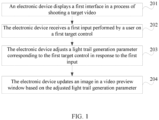
- the method may include the following step 201 to step 204.
- Step 201 An electronic device displays a first interface in a process of shooting a target video.
- the target video is a video of a light trail generation process
- the first interface includes a video preview window and at least one first control, and each first control is used to adjust a light trail generation parameter.
- the video preview window is used to display a preview image (which may also be referred to as a preview picture) shot in real time in the process of shooting the target video.
- each first control may be a control in a form of a progress bar, a control in a form of a key, or a control in another form. This is not limited in this embodiment of this application.
- the light trail generation parameter may include at least one of the following: a quantity of simultaneously generated light trails, and a generation speed of a light trail in a generation state, and may further include another generation parameter. This is not limited in this embodiment of this application.
- the at least one control includes at least one of the following: a quantity control and a speed control.
- the quantity control is used to adjust a quantity of simultaneously generated light trails
- the speed control is used to adjust a generation speed of a light trail in a generation state.
- the quantity control may also be referred to as a "simultaneously generated quantity control", and the speed control may also be referred to as an “individually generated speed control”. This is not limited in this embodiment of this application.
- the quantity of simultaneously generated light trails is not limited, because the quantity of simultaneously generated light trails is determined based on an actual shooting scene.
- a generation speed of a single light trail is controlled by controlling a frame rate of the target video.
- Step 202 The electronic device receives a first input performed by a user on a first target control.
- the first target control is a control in the at least one first control.
- the first input may be a tap input performed by the user on the first target control, or may be a drag input performed by the user on the first target control, or may be another feasibility input. This may be specifically determined based on an actual use situation, and is not limited in this embodiment of this application.
- the tap input may be an input of any number of taps such as a single-tap input or a double-tap input, or may be a short-press input or a touch and hold input.
- the drag input may be a drag input in any direction, such as an upward drag input, a downward drag input, a leftward drag input, or a rightward drag input.
- Step 203 The electronic device adjusts a light trail generation parameter corresponding to the first target control in response to the first input.
- the electronic device adjusts the quantity of simultaneously generated light trails in response to the first input. If the first target control is the speed control, the electronic device adjusts the light trail generation speed in response to the first input.
- Step 204 The electronic device updates an image in the video preview window based on the adjusted light trail generation parameter.
- the user opens a camera application, and taps a "light stream shutter mode” option to enter a streamer shutter video shooting mode.
- an interface that is, a first interface
- the streamer shutter video shooting mode is displayed, where a mark "1" indicates a video preview window, and a preview image currently shot is displayed in the video preview window; a mark “2" indicates a quantity control, and currently the quantity control is “unlimited”; and a mark “3" indicates a speed control, and currently the speed control is "50%”.
- the electronic device shoots a streamer shutter video (a target video) based on a light trail generation parameter specified by the user.
- the electronic device displays a processed image in the video preview window after performing corresponding processing on the shot image.
- a first interface may be displayed in a process of shooting a target video, where the target video is a video of a light trail generation process, and the first interface includes a video preview window and at least one first control; a first input performed by a user on a first target control is received, where the first target control is a control in the at least one first control; and a light trail generation parameter corresponding to the first target control is adjusted in response to the first input, and an image in the video preview window is updated based on the adjusted light trail generation parameter.
- the user may adjust the light trail generation parameter through the first input on the first target control (a control in the at least one first control, where each first control is used to adjust a light trail generation parameter), and update the image in the video preview window.
- the user can change a generation parameter (that is, adjust a shooting form) in a light trail generation process through an input, so that shooting forms are diversified, and a problem that a shooting form is single because a light trail generation parameter is fixed in the related art can be resolved.
- the first target control is a quantity control in the at least one first control
- the light trail generation parameter is a quantity of simultaneously generated light trails
- a first image is displayed in the video preview window before the first input; and the foregoing step 204 may be specifically implemented by the following step 204a.
- Step 204a The electronic device updates the first image in the video preview window to a second image based on the first input.
- the electronic device updates the first image in the video preview window to a third image in a case that the first input is not received.
- lengths of N light trails in the second image are increased (that is, it indicates that the quantity of simultaneously generated light trails is N)
- lengths of M light trails in the third image are increased (that is, it indicates that the quantity of simultaneously generated light trails is M)
- N and M are positive integers, and N and M are different.
- the quantity of simultaneously generated light trails in the shot video clip (for example, the third image) is M in a case that the first input is not received.
- the first input is an input performed by the user on the quantity control to trigger the electronic device to adjust a quantity of simultaneously generated light trails in a subsequently shot video clip from M to N.
- the electronic device obtains the second image in response to the first input, and updates the first image in the video preview window to the second image.
- the second image in addition to the N light trails, the second image may include at least one light trail whose length stops increasing, and in addition to the M light trails, the third image may include at least one light trail whose length stops increasing. This is not limited in this embodiment of this application.
- the N light trails and the M light trails may be completely different, or may be partially the same and partially different. If N is less than M, the N light trails may be light trails in the M light trails; or if N is greater than M, the N light trails may include the M light trails. This may be specifically determined based on an actual situation, and is not limited in this embodiment of this application.
- the user may specify which light trails in the second image are the N light trails through an input (for example, an input of specifying specific light trails or an input of specifying light trails in a specific region in a shooting field of view, which is not limited in this embodiment of this application).
- the user adjusts the quantity of simultaneously generated light trails in the video clip in the period of time through the first input, so that shooting forms can be diversified.
- an actually shot light trail generation image does not change.
- an image whose generation parameter changes hereinafter referred to as a processed image
- the processed image is displayed in the video preview window, and the target video is obtained based on the processed image.
- the shooting control method provided in this embodiment of this application may further include the following step 10 to step 13.
- Step 10 The electronic device obtains an image 1 (the image 1 is an actually shot light trail generation image).
- Step 11 The electronic device performs image segmentation processing on the image 1 to obtain S light trail images 1, where each light trail image 1 is an image of a light trail (a light trail in the image 1) whose length is increased and that is corresponding to a light trail in an actually shot previous frame of image (a light trail image in an actual scene), where S is a positive integer greater than or equal to P, and P is a larger value in M and N.
- Step 12 The electronic device performs image segmentation processing on the first image to obtain an intermediate image 1, where the intermediate image 1 is an image obtained after N light trail images 2 are segmented from the first image, and each light trail image 2 is an image of a light trail corresponding to one of the N light trails in the first image.
- Step 13 The electronic device performs image composition processing on the intermediate image 1 and the N light trail images 3 to obtain the second image.
- each light trail image 3 in the N light trail images 3 is a light trail image with a shortest light trail length in a light trail image 1 corresponding to a light trail 1 in the S light trail images 1 and a previously saved light trail image set corresponding to the light trail 1 (if there is a previously saved light trail image in the N light trail images 3, the saved light trail image is deleted from a storage region after step 13), where the light trail 1 is one light trail in the N light trails, and different light trail images 3 correspond to different light trails in the N light trails.
- each of the N light trail images 3 is any light trail image in a light trail image 1 corresponding to a light trail 1 in the S light trail images 1 and a previously saved light trail image set corresponding to the light trail 1.
- the light trail 1 is a light trail corresponding to each light trail image 3 in the N light trails. That is, the light trail 1 is one of the N light trails, and different light trail images 3 correspond to different light trails in the N light trails.
- each light trail whose generation parameter is controlled there is a corresponding light trail image set.
- a light trail image set (the light trail image set is empty), or there may be no light trail image set.
- a light trail image set may be initially generated during shooting of the target video, or may be generated only in a case that a generation parameter of a corresponding light trail is controlled. This is not limited in this embodiment of this application.
- the light trail image set may be a set, or may not be a set (only a separate storage region). This is not limited in this embodiment of this application.
- the shooting control method provided in this embodiment of this application may further include the following step 14.
- Step 14 The electronic device saves a light trail image 1 other than a light trail image 1 that is the same as a light trail image in the N light trail images 3 in the S light trail images 1.
- a shooting scene of the target video actually includes four light trails: a light trail a, a light trail b, a light trail c, and a light trail d, respectively. That is, in a case that the shooting control method provided in this embodiment of this application is not implemented, the target video is a process generation video of the four light trails.
- the target video is a process generation video of the four light trails.
- the four light trails (the light trail a, the light trail b, the light trail c, and the light trail d) are simultaneously generated.
- an input 1 performed by the user to reduce the quantity of simultaneously generated light trails from 4 to 2 (the quantity control is adjusted from 4 to 2) is received.
- a next video clip 2 two light trails (the light trail a and the light trail b) are simultaneously generated, and generation of two light trails (the light trail c and the light trail d) stops when the input 1 is received.
- a light trail image corresponding to the light trail c is segmented and is saved in a light trail image set c frame by frame
- a light trail image corresponding to the light trail d is segmented and is saved in a light trail image set d frame by frame.
- a shortest light trail image is obtained from the light trail image set c frame by frame (the light trail image is deleted from the light trail image set c) to replace a light trail image corresponding to the light trail c in the frame-by-frame light trail generation image that is actually shot (the replaced light trail image is saved in the light trail image set c) (that is, a frame-by-frame shortest light trail image X obtained from the light trail image set c is exchanged with a light trail image y corresponding to the light trail c in the frame-by-frame light trail generation image that is actually shot).
- One light trail (the light trail d) continues stopping being generated, and in the frame-by-frame light trail generation image that is actually shot in this process, a light trail image corresponding to the light trail d is segmented and is saved in the light trail image set d.
- an input 3 performed by the user to reduce the quantity of simultaneously generated light trails from 3 to 1 (the quantity control is adjusted from 3 to 1) is received.
- one light trail (the light trail a) continues being generated, two light trails (the light trail b and the light trail c) change from being generated to stopping being generated, and one light trail (the light trail d) continues stopping being generated.
- a light trail image corresponding to the light trail b is segmented and is saved in a light trail image set b frame by frame
- a light trail image corresponding to the light trail c is segmented and is saved in the light trail image set c frame by frame
- a light trail image corresponding to the light trail d is segmented and is saved in the light trail image set d frame by frame.
- the electronic device in a case that another input (an input on any first control or an input of stopping shooting the target video) is not received after the first input, the electronic device cyclically performs the foregoing step 10 to step 14 to obtain a video clip after the first input (in the target video).
- an image whose generation parameter changes may be obtained (a processed image, namely, the second image)
- the processed image is displayed in the video preview window, and the target video is obtained based on the processed image.
- the shooting control method provided in this embodiment of this application may further include the following step 204b to step 204c.
- Step 204b The electronic device obtains the third image.
- Step 204c The electronic device performs target processing on the third image to obtain the second image.
- the target processing is processing corresponding to the first input.
- the target processing includes image segmentation processing and image composition processing, and may further include another image processing method. This may be specifically determined based on an actual use requirement, and is not limited in this embodiment of this application.
- the third image is an actual light trail generation image shot by the electronic device based on a shooting scene. If the electronic device receives another input on any first control before the first input, the third image may be the foregoing actual light trail generation image, or may be an image obtained after the actual light trail generation image is processing (processing corresponding to the another input).
- the electronic device in a case that another input (an input on any first control or an input of stopping shooting the target video) is not received after the first input, the electronic device cyclically performs the foregoing step 204b to step 204c to obtain a video clip after the first input (in the target video).
- the third image is obtained, and target processing is performed on the third image to obtain the second image, so that a light trail generation image required by the user can be obtained, and further a light trail generation video required by the user can be obtained.
- the M light trails include the N light trails (that is, generation of a part of light trails in the original light trails that are simultaneously generated is controlled to stop).
- the foregoing step 204c may be specifically implemented by the following step 101 to step 103.
- Step 101 The electronic device performs image segmentation processing on the third image to obtain a first intermediate image.
- the first intermediate image is an image obtained after (M-N) first light trail images are segmented from the third image, and each first light trail image is an image of one light trail other than the N light trails in the M light trails.
- Step 102 The electronic device performs image segmentation processing on the first image to obtain (M-N) second light trail images.
- Each second light trail image is an image of one light trail other than the N light trails in the M light trails.
- Step 103 The electronic device performs image composition processing on the first intermediate image and the (M-N) second light trail images to obtain the second image.
- step 101 may be specifically implemented by the following step 101a.
- the shooting control method provided in this embodiment of this application may further include the following step 104.
- Step 101a The electronic device performs image segmentation processing on the third image to obtain the first intermediate image and the (M-N) first light trail images.
- Step 104 The electronic device saves the (M-N) first light trail images.
- step 101 to step 104 may be an input that is performed by the user to adjust the quantity control to reduce the quantity of simultaneously generated light trails and that is received after the user taps the "shooting" option to start shooting the target video (or an input that is performed by the user to adjust the quantity control to reduce the quantity of simultaneously generated light trails and that is received again after the user adjusts the quantity control for a plurality of times in the process of shooting the target video).
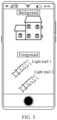
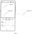
- the electronic device extracts, by using an image segmentation technology, an image of reduced light trails (light trails other than the N light trails in the M light trails) that are (actually) being generated (as shown in FIG.
- a background and a foreground of an image may be segmented or a light trail 1 and a light trail 2 in the foreground may be segmented by using the image segmentation technology.
- the light trail 2 is segmented and saved), and then save the extracted image frame by frame for subsequent processing. Generation of the reduced light trails that are (actually) being generated stops in the video preview window.
- the image displayed in the video preview window includes only the simultaneously generated light trails specified by the user.
- an image of extra light trails may be first segmented and saved.
- the electronic device may extract, from a storage region, the previously saved light trail image corresponding to the part or all of the light trails, and then compose the light trail image into a preview image to be displayed in the video preview window, to reflect a generation process of the part or all of the light trails.
- the N light trails include the M light trails (that is, in a case that the original M light trails continue to be generated, some light trails whose generation has been previously controlled to stop are added, and generation is resumed).
- the foregoing step 204c may be specifically implemented by the following step 105 to step 106.
- Step 105 The electronic device obtains (N-M) third light trail images.
- Each third light trail image is a light trail image with a shortest light trail length that is in a light trail image set corresponding to one first target light trail and that is saved before the first input, and the one first target light trail is one of (N-M) light trails other than the M light trails in the N light trails.
- Step 106 The electronic device performs image composition processing on the third image and the (N-M) third light trail images to obtain the second image.
- the third image may not include a light trail or may include a light trail other than the M light trail images
- the third image does not include the (N-M) light trails other than the M light trail images (the third image does not include the (N-M) light trails)
- the third image includes the (N-M) light trails other than the M light trail images (the third image includes the (N-M) light trails)
- the third image includes a part of the (N-M) light trails other than the M light trail images (the third image includes a part of the (N-M) light trails).
- composition processing in step 106 may be inserting a third light trail image corresponding to the light trail that is not in the third image into a corresponding position in the third image.
- composition processing in step 106 may be replacing a third light trail image corresponding to the light trail that is not in the third image with a light trail image at a corresponding position in the third image.
- step 106 may be specifically implemented by the following step 106a to step 106b.
- Step 106a The electronic device performs image segmentation processing on the third image to obtain a second intermediate image.
- the second intermediate image is an image obtained after (N-M) fifth light trail images are segmented from the third image, and each fifth light trail image is an image of one light trail other than the M light trails in the N light trails.
- one fifth light trail image corresponds to one third light trail image
- different fifth light trail images correspond to different third light trail images.
- a length of a light trail in each light trail image in the light trail image set is greater than a length of a light trail in a corresponding fifth light trail image.
- the fifth light trail image is an image of one light trail whose length is not increased in the third image
- all saved light trail images in the light trail image set are light trail images whose actual lengths are increased but that are not displayed in the video preview window.
- Step 106b The electronic device performs image composition processing on the second intermediate image and the (N-M) third light trail images to obtain the second image.
- step 105 to step 106 are performed after the user decreases the quantity of simultaneously generated light trails and a specified quantity of light trail images are buffered and then the user increases the quantity of simultaneously generated light trails (generation of a part or all of light trails that are previously controlled to stop being generated is resumed).
- a real-time generated image of the part or all of the light trails may be segmented and saved, and then a previously saved corresponding light trail image is extracted and composed into a preview image to be displayed in the video preview window, that is, a large quantity of previously buffered light trail images are displayed in the video preview window.
- the first interface further includes at least one second control.
- Each second control is used to determine a distribution mode of the (N-M) third light trail images.
- the shooting control method provided in this embodiment of this application may further include the following step 107 to step 108.
- the foregoing step 105 may be specifically implemented by the following step 105a.
- Step 107 The electronic device receives a second input performed by the user on a second target control.
- the second target control is a control in the at least one second control.
- the at least one second control includes at least one of the following: a single-point diffusion distribution control, a multi-point diffusion distribution control, a uniform distribution control, and a random distribution control.
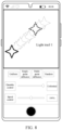
- the at least one second control includes a single-point diffusion distribution control, a multi-point diffusion distribution control, a uniform distribution control, and a random distribution control that are respectively corresponding to "single-point diffusion”, “multi-point diffusion”, “uniform”, and "random” that are indicated by a mark "4" in FIG. 2 .
- a single-point diffusion distribution control is used to control light trails whose generation resume to be distributed around one central point (that is, a light trail near the central point is preferentially selected for generation resumption, and then a light trail far away from the central point is selected for generation resumption).
- a multi-point diffusion distribution control is used to control light trails whose generation resume to be separately distributed around a plurality of central points (that is, any light trail near two central points is preferentially selected for generation resumption, and then any light trail away from the two central points is selected for generation resumption).
- a uniform distribution control is used to control light trails whose generation resume to be uniformly distributed in an image, instead of being distributed on any point or a plurality of points.
- a random distribution control is used to control light trails whose generation resume to be randomly distributed in an image, without limiting a distribution form.
- Step 108 In response to the second input, the electronic device determines that a distribution mode of the (N-M) third light trail images is a target mode.
- Step 105a In response to the second input, the electronic device obtains (N-M) fourth light trail images whose distribution mode is the target mode from the K fourth light trail images as the (N-M) third light trail images.
- Each fourth light trail image is a light trail image with a shortest light trail length that is in a light trail image set corresponding to one second target light trail and that is saved before the first input, and the one second target light trail is one light trail other than the M light trails, where K is a positive integer greater than (N-M).
- the electronic device controls light trails whose generation resume to be spread outward around a center point specified by the user. If the user does not select any second control, the electronic device may control light trails to be sequentially distributed in an original order (an order of appearance time points of the light trails).
- the at least one second control is added, and the user may select a corresponding second control based on a requirement of the user, so that light trails whose generation resume are distributed based on the requirement of the user, thereby increasing a shooting form.
- the first target control is a speed control in the at least one first control
- the light trail generation parameter is a light trail generation speed
- the speed control is used to adjust a generation speed of a light trail in a generation state.
- Step 204d The electronic device updates the image in the video preview window at a first frame rate within a first time period.
- a start moment of the first time period is a moment at which the first input is received
- an end moment of the first time period is a moment at which a target input is received
- the target input is any one of the following: an input on a control in the at least one first control, and an input of stopping shooting the target video.
- the first frame rate is determined based on the first input, and the image in the video preview window is updated at a second frame rate in a case that the first input is not received, where the second frame rate is different from the first frame rate.
- the user adjusts a frame rate of a video through the first input on the speed control, so that a light trail generation speed can be changed. If the frame rate is reduced, the light trail generation speed is reduced; or if the frame rate is increased, the light trail generation speed is increased. In this way, a shooting form can be increased.
- the shooting control method provided in this embodiment of this application may further include the following step 205.
- Step 205 The electronic device saves a first target image.
- the first target image is an image that is not updated in the video preview window within the first time period.
- the electronic device may first save the first target image to be used when the frame rate is subsequently increased.
- a frame rate is reduced, that is, a light trail generation speed is reduced.
- the electronic device may save an obtained preview image, and then display the obtained preview image in the video preview window at a speed of F* (X%) frames per second, where X% is a value of the speed control specified by the user, and F frames per second are a frame rate before the first input.
- the shooting control method provided in this embodiment of this application may further include the following step 206.
- the foregoing step 204d may be specifically implemented by the following step 204d1.
- Step 206 The electronic device obtains a second target image, where the second target image is an image that is not updated in the video preview window and that is saved before the first input.
- Step 204d1 The electronic device updates the image in the video preview window at the first frame rate within the first time period based on the second target image and a third target image.
- the third target image is an image generated within the first time period.
- this step can increase the light trail generation speed by increasing the frame rate, so that the light trail generation speed is even greater than an actual generation speed (greater than F frames per second).
- the electronic device saves a currently generated image frame by frame, and then redisplays, in the video preview window at a speed of F* (Y%) frames per second, an image that is previously buffered frame by frame, where Y% is a value of the speed control specified by the user.
- the user may alternatively end shooting by tapping a "stop shooting" key, and generate the target video.
- the user may manually stop video recording, and the electronic device saves a recorded video locally for viewing by the user.
- the user in a process of shooting a video of a light trail generation process, in a streamer shutter video mode of a camera of the electronic device, the user may adjust a light trail generation speed through an input on the speed control, so that a light trail is delayed or accelerated to be generated.
- the shooting control method provided in the embodiments of this application may be performed by a shooting control apparatus, or a functional module and/or a functional entity for performing the shooting control method in the shooting control apparatus.
- that the shooting control apparatus performs the shooting control method is used as an example to describe the shooting control method provided in the embodiments of this application.
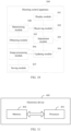
- FIG. 10 is a possible schematic structural diagram of a shooting control apparatus according to an embodiment of this application.
- a shooting control apparatus 300 may include a display module 301, a receiving module 302, an adjustment module 303, and an updating module 304.
- the display module 301 is configured to display a first interface in a process of shooting a target video, where the target video is a video of a light trail generation process, and the first interface includes a video preview window and at least one first control.
- the receiving module 302 is configured to receive a first input performed by a user on a first target control, where the first target control is a control in the at least one first control.
- the adjustment module 303 is configured to adjust a light trail generation parameter corresponding to the first target control in response to the first input received by the receiving module.
- the updating module 304 is configured to update an image in the video preview window based on the adjusted light trail generation parameter.
- the first target control is a quantity control in the at least one first control
- the light trail generation parameter is a quantity of simultaneously generated light trails
- a first image is displayed in the video preview window before the first input
- the updating module 304 is specifically configured to update the first image in the video preview window to a second image
- the updating module 304 is configured to update the first image in the video preview window to a third image in a case that the first input is not received, where compared with the first image, lengths of N light trails in the second image are increased, and compared with the first image, lengths of M light trails in the third image are increased, where N and M are positive integers, and N and M are different.
- the shooting control apparatus 300 further includes an obtaining module 305 and an image processing module 306.
- the obtaining module 305 is configured to obtain the third image before the updating module 304 updates the first image in the video preview window to the second image.
- the image processing module 306 is configured to perform target processing on the third image to obtain the second image.
- the M light trails include the N light trails
- the image processing module 306 is specifically configured to: perform image segmentation processing on the third image to obtain a first intermediate image, where the first intermediate image is an image obtained after (M-N) first light trail images are segmented from the third image, and each first light trail image is an image of one light trail other than the N light trails in the M light trails; perform image segmentation processing on the first image to obtain (M-N) second light trail images, where each second light trail image is an image of one light trail other than the N light trails in the M light trails; and perform image composition processing on the first intermediate image and the (M-N) second light trail images to obtain the second image.
- the shooting control apparatus 300 further includes a saving module 307.
- the image processing module 306 is specifically configured to perform image segmentation processing on the third image to obtain the first intermediate image and the (M-N) first light trail images.
- the saving module 307 is configured to save the (M-N) first light trail images.
- the N light trails include the M light trails
- the image processing module 306 is configured to: obtain (N-M) third light trail images; and perform image composition processing on the third image and the (N-M) third light trail images to obtain the second image, where each third light trail image is a light trail image with a shortest light trail length that is in a light trail image set corresponding to one first target light trail and that is saved before the first input, and the one first target light trail is one of (N-M) light trails other than the M light trails in the N light trails.
- the shooting control apparatus 300 apparatus further includes a determining module 308.
- the first interface further includes at least one second control
- the receiving module 302 is further configured to: before the (N-M) third light trail images are obtained, receive a second input performed by a user on a second target control, where the second target control is a control in the at least one second control.
- the determining module 308 is configured to: in response to the second input received by the receiving module, determine that a distribution mode of the (N-M) third light trail images is a target mode.
- the obtaining module 305 is specifically configured to obtain, (N-M) fourth light trail images whose distribution mode is the target mode from the K fourth light trail images as the (N-M) third light trail images, where each fourth light trail image is a light trail image with a shortest light trail length that is in a light trail image set corresponding to one second target light trail and that is saved before the first input, and the one second target light trail is one light trail other than the M light trails, where K is a positive integer greater than (N-M).
- the at least one second control includes at least one of the following: a single-point diffusion distribution control, a multi-point diffusion distribution control, a uniform distribution control, and a random distribution control.
- the first target control is a speed control in the at least one first control
- the light trail generation parameter is a light trail generation speed.
- the updating module 304 is specifically configured to: update the image in the video preview window at a first frame rate within a first time period, where a start moment of the first time period is a moment at which the first input is received, an end moment of the first time period is a moment at which a target input is received, and the target input is any one of the following: an input on a control in the at least one first control, and an input of stopping shooting the target video; and update the image in the video preview window at a second frame rate in a case that the first input is not received, where the second frame rate is different from the first frame rate.
- the shooting control apparatus 300 further includes a saving module 307.
- the saving module 307 configured to: in a case that the first frame rate is less than the second frame rate, save a first target image after the image in the video preview window is updated at the first frame rate within the first time period, where the first target image is an image that is not updated in the video preview window within the first time period.
- the shooting control apparatus 300 further includes an obtaining module 305.
- the obtaining module 305 is configured to: in a case that the first frame rate is greater than the second frame rate, obtain a second target image before the image in the video preview window is updated at the first frame rate within the first time period, where the second target image is an image that is not updated in the video preview window and that is saved before the first input.
- the updating module 304 is specifically configured to update the image in the video preview window at the first frame rate within the first time period based on the second target image and a third target image, where the third target image is an image generated within the first time period.
- modules certainly included in the shooting control apparatus 300 are shown in a solid line box, such as the display module 301, the receiving module 302, the adjustment module 303, and the updating module 304; and modules that may be included or may not be included in the shooting control apparatus 300 are shown in a dotted line box, such as the obtaining module 305, the image processing module 306, the saving module 307, and the determining module 308.
- a first interface may be displayed in a process of shooting a target video, where the target video is a video of a light trail generation process, and the first interface includes a video preview window and at least one first control; a first input performed by a user on a first target control is received, where the first target control is a control in the at least one first control; and a light trail generation parameter corresponding to the first target control is adjusted in response to the first input, and an image in the video preview window is updated based on the adjusted light trail generation parameter.
- the user may adjust the light trail generation parameter through the first input on the first target control (a control in the at least one first control, where each first control is used to adjust a light trail generation parameter), and update the image in the video preview window.
- the user can change a generation parameter (that is, adjust a shooting form) in a light trail generation process through an input, so that shooting forms are diversified, and a problem that a shooting form is single because a light trail generation parameter is fixed in the related art can be resolved.
- the shooting control apparatus in this embodiment of this application may be an apparatus, or may be an electronic device or a component, an integrated circuit, or a chip in the electronic device.
- the electronic device may be a mobile electronic device, or may be a non-mobile electronic device.
- the mobile electronic device may be a mobile phone, a tablet computer, a laptop computer, a palmtop computer, an in-vehicle electronic device, a wearable device, an ultra-mobile personal computer (ultra-mobile personal computer, UMPC), a netbook, or a personal digital assistant (personal digital assistant, PDA).
- the non-mobile electronic device may be a server, a network attached storage (Network Attached Storage, NAS), a personal computer (personal computer, PC), a television (television, TV), an automated teller machine, or a self-service machine. This is not specifically limited in this embodiment of this application.
- Network Attached Storage NAS
- PC personal computer
- TV television
- automated teller machine or a self-service machine. This is not specifically limited in this embodiment of this application.
- the shooting control apparatus in this embodiment of this application may be an apparatus with an operating system.
- the operating system may be an Android (Android) operating system, an iOS operating system, or another possible operating system. This is not specifically limited in the embodiments of this application.
- the shooting control apparatus provided in this embodiment of this application can implement the processes implemented in the method embodiments in FIG. 1 to FIG. 9 , and can achieve a same technical effect. To avoid repetition, details are not described herein again.
- an embodiment of this application further provides an electronic device 400, including a processor 401, a memory 402, and a program or an instruction that is stored in the memory 402 and executable on the processor 401.
- the program or the instruction is executed by the processor 401, the processes of the foregoing shooting control method embodiment are implemented and a same technical effect can be achieved. To avoid repetition, details are not described herein again.
- the electronic device in this embodiment of this application includes the foregoing mobile electronic device and the foregoing non-mobile electronic device.
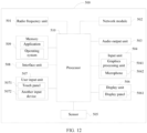
- FIG. 12 is a schematic structural diagram of hardware of an electronic device according to an embodiment of this application.
- An electronic device 500 includes but is not limited to components such as a radio frequency unit 501, a network module 502, an audio output unit 503, an input unit 504, a sensor 505, a display unit 506, a user input unit 507, an interface unit 508, a memory 509, and a processor 510.
- the electronic device 500 may further include a power supply (for example, a battery) that supplies power to each component.
- the power supply may be logically connected to the processor 510 by using a power supply management system, to implement functions such as charging and discharging management, and power consumption management by using the power supply management system.
- the structure of the electronic device shown in FIG. 12 does not constitute a limitation on the electronic device.
- the electronic device may include components more or fewer than those shown in the diagram, a combination of some components, or different component arrangements. Details are not described herein.
- the display unit 506 is configured to display a first interface in a process of shooting a target video, where the target video is a video of a light trail generation process, and the first interface includes a video preview window and at least one first control.
- the user input unit 507 is configured to receive a first input performed by a user on a first target control, where the first target control is a control in the at least one first control.
- the processor 510 is configured to: adjust a light trail generation parameter corresponding to the first target control in response to the first input, and update an image in the video preview window based on the adjusted light trail generation parameter.
- the first target control is a quantity control in the at least one first control
- the light trail generation parameter is a quantity of simultaneously generated light trails
- a first image is displayed in the video preview window before the first input
- the processor 510 is specifically configured to update the first image in the video preview window to a second image
- the processor 510 is configured to update the first image in the video preview window to a third image in a case that the first input is not received, where compared with the first image, lengths of N light trails in the second image are increased, and compared with the first image, lengths of M light trails in the third image are increased, where N and M are positive integers, and N and M are different.
- the processor 510 is further configured to: obtain the third image before the first image in the video preview window is updated to the second image, and perform target processing on the third image to obtain the second image.
- the M light trails include the N light trails
- the processor 510 is specifically configured to: perform image segmentation processing on the third image to obtain a first intermediate image, where the first intermediate image is an image obtained after (M-N) first light trail images are segmented from the third image, and each first light trail image is an image of one light trail other than the N light trails in the M light trails; perform image segmentation processing on the first image to obtain (M-N) second light trail images, where each second light trail image is an image of one light trail other than the N light trails in the M light trails; and perform image composition processing on the first intermediate image and the (M-N) second light trail images to obtain the second image.
- the processor 510 is specifically configured to perform image segmentation processing on the third image to obtain the first intermediate image and the (M-N) first light trail images; and is further configured to save the (M-N) first light trail images.
- the N light trails include the M light trails
- the processor 510 is configured to: obtain (N-M) third light trail images; and perform image composition processing on the third image and the (N-M) third light trail images to obtain the second image, where each third light trail image is a light trail image with a shortest light trail length that is in a light trail image set corresponding to one first target light trail and that is saved before the first input, and the one first target light trail is one of (N-M) light trails other than the M light trails in the N light trails.
- the first interface further includes at least one second control
- the user input unit 507 is further configured to: before the (N-M) third light trail images are obtained, receive a second input performed by a user on a second target control, where the second target control is a control in the at least one second control.
- the processor 510 is further configured to: in response to the second input, determine that a distribution mode of the (N-M) third light trail images is a target mode.
- the processor 510 is specifically configured to obtain, (N-M) fourth light trail images whose distribution mode is the target mode from the K fourth light trail images as the (N-M) third light trail images, where each fourth light trail image is a light trail image with a shortest light trail length that is in a light trail image set corresponding to one second target light trail and that is saved before the first input, and the one second target light trail is one light trail other than the M light trails, where K is a positive integer greater than (N-M).
- the at least one second control includes at least one of the following: a single-point diffusion distribution control, a multi-point diffusion distribution control, a uniform distribution control, and a random distribution control.
- the first target control is a speed control in the at least one first control
- the light trail generation parameter is a light trail generation speed.
- the processor 510 is specifically configured to: update the image in the video preview window at a first frame rate within a first time period, where a start moment of the first time period is a moment at which the first input is received, an end moment of the first time period is a moment at which a target input is received, and the target input is any one of the following: an input on a control in the at least one first control, and an input of stopping shooting the target video; and update the image in the video preview window at a second frame rate in a case that the first input is not received, where the second frame rate is different from the first frame rate.
- the processor 510 is further configured to: in a case that the first frame rate is less than the second frame rate, save a first target image after the image in the video preview window is updated at the first frame rate within the first time period, where the first target image is an image that is not updated in the video preview window within the first time period.
- the processor 510 is further configured to: in a case that the first frame rate is greater than the second frame rate, obtain a second target image before the image in the video preview window is updated at the first frame rate within the first time period, where the second target image is an image that is not updated in the video preview window and that is saved before the first input; and is further specifically configured to update the image in the video preview window at the first frame rate within the first time period based on the second target image and a third target image, where the third target image is an image generated within the first time period.
- a first interface may be displayed in a process of shooting a target video, where the target video is a video of a light trail generation process, and the first interface includes a video preview window and at least one first control; a first input performed by a user on a first target control is received, where the first target control is a control in the at least one first control; and a light trail generation parameter corresponding to the first target control is adjusted in response to the first input, and an image in the video preview window is updated based on the adjusted light trail generation parameter.
- the user may adjust the light trail generation parameter through the first input on the first target control (a control in the at least one first control, where each first control is used to adjust a light trail generation parameter), and update the image in the video preview window.
- the user can change a generation parameter (that is, adjust a shooting form) in a light trail generation process through an input, so that shooting forms are diversified, and a problem that a shooting form is single because a light trail generation parameter is fixed in the related art can be resolved.
- the radio frequency unit 501 may be configured to receive and send information or a signal in a call process. Specifically, after receiving downlink data from a base station, the radio frequency unit 501 sends the downlink data to the processor 510 for processing. In addition, the radio frequency unit 501 sends uplink data to the base station. In addition, the radio frequency unit 501 may communicate with a network and another device through a wireless communication system. The electronic device provides wireless broadband Internet access for the user by using the network module 502, for example, helping the user to send and receive an e-mail, brows a web page, and access streaming media.
- the audio output unit 503 may convert audio data received by the radio frequency unit 501 or the network module 502 or stored in the memory 509 into an audio signal and output the audio signal as a sound. In addition, the audio output unit 503 may further provide an audio output (for example, a call signal received voice, or a message received voice) related to a specific function implemented by the electronic device 500.
- the input unit 504 may include a graphics processing unit (Graphics Processing Unit, GPU) 5041 and a microphone 5042, and the graphics processing unit 5041 processes image data of a still picture or video obtained by an image capture apparatus (such as a camera) in a video capture mode or an image capture mode.
- the display unit 506 may include a display panel 5061.
- the display panel 5061 may be configured in a form such as a liquid crystal display or an organic light-emitting diode.
- the user input unit 507 includes a touch panel 5071 and another input device 5072.
- the touch panel 5071 is also referred to as a touchscreen.
- the touch panel 5071 may include two parts: a touch detection apparatus and a touch controller.
- the another input device 5072 may include but is not limited to a physical keyboard, a functional button (such as a volume control button or a power on/off button), a trackball, a mouse, and a joystick. Details are not described herein.
- the memory 509 may be configured to store a software program and various data, including but not limited to an application and an operating system.
- An application processor and a modem processor may be integrated into the processor 510, the application processor mainly processes an operating system, a user interface, an application, and the like, and the modem processor mainly processes wireless communication. It can be understood that, alternatively, the modem processor may not be integrated into the processor 510.
- An embodiment of this application further provides a readable storage medium.
- the readable storage medium stores a program or an instruction, and when the program or the instruction is executed by a processor, the processes of the foregoing shooting control method embodiment are implemented and a same technical effect can be achieved. To avoid repetition, details are not described herein again.
- the processor is a processor in the electronic device in the foregoing embodiment.
- the readable storage medium includes a computer-readable storage medium, such as a computer read-only memory (Read-Only Memory, ROM), a random access memory (Random Access Memory, RAM), a magnetic disk, or an optical disc.
- An embodiment of this application further provides a chip.
- the chip includes a processor and a communication interface, the communication interface is coupled to the processor, and the processor is configured to run a program or an instruction to implement the processes of the foregoing shooting control method embodiment, and a same technical effect can be achieved. To avoid repetition, details are not described herein again.
- the chip mentioned in this embodiment of this application may also be referred to as a system-level chip, a system chip, a chip system, or an on-chip system chip.
- the terms "include”, “comprise”, or their any other variant is intended to cover a non-exclusive inclusion, so that a process, a method, an article, or an apparatus that includes a list of elements not only includes those elements but also includes other elements which are not expressly listed, or further includes elements inherent to such process, method, article, or apparatus.
- An element limited by “including a " does not, without more constraints, preclude the presence of additional identical elements in the process, method, article, or apparatus that includes the element.
- the scope of the method and the apparatus in the embodiments of this application is not limited to performing functions in an illustrated or discussed sequence, and may further include performing functions in a basically simultaneous manner or in a reverse sequence according to the functions concerned.
- the described method may be performed in an order different from that described, and the steps may be added, omitted, or combined.
- features described with reference to some examples may be combined in other examples.
- the method in the foregoing embodiment may be implemented by software in addition to a necessary universal hardware platform or by hardware only. In most circumstances, the former is a preferred implementation. Based on such an understanding, the technical solutions of this application essentially or the part contributing to the prior art may be implemented in a form of a software product.
- the computer software product is stored in a storage medium (such as a ROM/RAM, a hard disk, or an optical disc), and includes several instructions for instructing a terminal (which may be mobile phone, a computer, a server, an air conditioner, a network device, or the like) to perform the methods described in the embodiments of this application.
Landscapes
- Engineering & Computer Science (AREA)
- Multimedia (AREA)
- Signal Processing (AREA)
- Human Computer Interaction (AREA)
- Physics & Mathematics (AREA)
- General Physics & Mathematics (AREA)
- Computer Vision & Pattern Recognition (AREA)
- Theoretical Computer Science (AREA)
- Studio Devices (AREA)
- Indication In Cameras, And Counting Of Exposures (AREA)
- User Interface Of Digital Computer (AREA)
Abstract
Description
- This application claims priority to
Chinese Patent Application No. 202110121815.5, filed on January 28, 2021 - This application pertains to the field of communication technologies, and specifically relates to a shooting control method and apparatus, and an electronic device.
- With rapid development of communication technologies, a shooting function of an electronic device is increasingly powerful, for example, a shooting function in a light stream shutter mode.
- In the light stream shutter mode, moving tracks of light and shadow and flowing water may be captured based on different light rays and shooting objects. The light stream shutter mode is generally used to shoot specific people and regular dynamic scenes, such as a starry sky, a waterfall, a stream, and a vehicle on the road. In addition, shooting in the light stream shutter mode may generate a strip-like dynamic effect. A streamer shutter video is recording a shooting process of the entire light stream shutter mode as a video.
- However, in a process of shooting a streamer shutter video, because a light trail generation parameter is fixed, a shooting form is single, and a user requirement cannot be met.
- Embodiments of this application aim to provide a shooting control method and apparatus, and an electronic device, to resolve a problem that a shooting form is single because a light trail generation parameter is fixed in a process of shooting a streamer shutter video.
- To resolve the technical problem, this application is implemented as follows:
- According to a first aspect, an embodiment of this application provides a shooting control method. The method includes: displaying a first interface in a process of shooting a target video, where the target video is a video of a light trail generation process, and the first interface includes a video preview window and at least one first control; receiving a first input performed by a user on a first target control, where the first target control is a control in the at least one first control; and adjusting a light trail generation parameter corresponding to the first target control in response to the first input, and updating an image in the video preview window based on the adjusted light trail generation parameter.
- According to a second aspect, an embodiment of this application provides a shooting control apparatus. The apparatus includes a display module, a receiving module, and an updating module, where the display module is configured to display a first interface in a process of shooting a target video, where the target video is a video of a light trail generation process, and the first interface includes a video preview window and at least one first control; the receiving module is configured to receive a first input performed by a user on a first target control, where the first target control is a control in the at least one first control; and the updating module is configured to: adjust a light trail generation parameter corresponding to the first target control in response to the first input, and update an image in the video preview window based on the adjusted light trail generation parameter.
- According to a third aspect, an embodiment of this application provides an electronic device. The electronic device includes a processor, a memory, and a program or an instruction that is stored in the memory and executable on the processor, where when the program or the instruction is executed by the processor, the steps of the method in the first aspect are implemented.
- According to a fourth aspect, an embodiment of this application provides a readable storage medium. The readable storage medium stores a program or an instruction, and when the program or the instruction is executed by a processor, the steps of the method in the first aspect are implemented.
- According to a fifth aspect, an embodiment of this application provides a chip. The chip includes a processor and a communication interface, the communication interface is coupled to the processor, and the processor is configured to run a program or an instruction to implement the method in the first aspect.
- In the embodiments of this application, a first interface may be displayed in a process of shooting a target video, where the target video is a video of a light trail generation process, and the first interface includes a video preview window and at least one first control; a first input performed by a user on a first target control is received, where the first target control is a control in the at least one first control; and a light trail generation parameter corresponding to the first target control is adjusted in response to the first input, and an image in the video preview window is updated based on the adjusted light trail generation parameter. In this solution, in the process of shooting the video of the light trail generation process, the user may adjust the light trail generation parameter through the first input on the first target control (a control in the at least one first control, where each first control is used to adjust a light trail generation parameter), and update the image in the video preview window. In this way, in a shooting process, the user can change a generation parameter (that is, adjust a shooting form) in a light trail generation process through an input, so that shooting forms are diversified, and a problem that a shooting form is single because a light trail generation parameter is fixed in the related art can be resolved.
-
-
FIG. 1 is a flowchart of a shooting control method according to an embodiment of this application; -
FIG. 2 is a first schematic diagram of an interface of a shooting control method according to an embodiment of this application; -
FIG. 3 is a second schematic diagram of an interface of a shooting control method according to an embodiment of this application; -
FIG. 4 is a third schematic diagram of an interface of a shooting control method according to an embodiment of this application; -
FIG. 5 is a fourth schematic diagram of an interface of a shooting control method according to an embodiment of this application; -
FIG. 6 is a fifth schematic diagram of an interface of a shooting control method according to an embodiment of this application; -
FIG. 7 is a sixth schematic diagram of an interface of a shooting control method according to an embodiment of this application; -
FIG. 8 is a seventh schematic diagram of an interface of a shooting control method according to an embodiment of this application; -
FIG. 9 is an eighth schematic diagram of an interface of a shooting control method according to an embodiment of this application; -
FIG. 10 is a schematic structural diagram of a shooting control apparatus according to an embodiment of this application; -
FIG. 11 is a schematic structural diagram of an electronic device according to an embodiment of this application; and -
FIG. 12 is a schematic structural diagram of hardware of an electronic device according to an embodiment of this application. - The following clearly and completely describes the technical solutions in the embodiments of this application with reference to the accompanying drawings in the embodiments of this application. Apparently, the described embodiments are some but not all of the embodiments of this application. All other embodiments obtained by a person of ordinary skill in the art based on the embodiments of this application without creative efforts shall fall within the protection scope of this application.
- In the specification and claims of this application, the terms "first", "second", and the like are intended to distinguish between similar objects but do not describe a specific order or sequence. It should be understood that, data used in such a way are interchangeable in proper circumstances, so that the embodiments of this application can be implemented in an order other than the order illustrated or described herein. Objects classified by "first", "second", and the like are usually of a same type, and the number of objects is not limited. For example, there may be one or more first objects. In addition, in the specification and the claims, "and/or" represents at least one of connected objects, and a character "/" generally represents an "or" relationship between associated objects.
- In the embodiments of this application, the word such as "example" or "for example" is used to represent giving an example, an illustration, or a description. Any embodiment or design scheme described as " example" or "for example" in the embodiments of this application should not be explained as being more preferred or having more advantages than another embodiment or design scheme. Exactly, use of the word "example" or "for example" is intended to present a concept in a specific manner.
- In the descriptions of the embodiments of this application, unless otherwise stated, "a plurality of" means two or more, for example, a plurality of processing units mean two or more processing units, and a plurality of elements mean two or more elements.
- With reference to the accompanying drawings, a shooting control method and apparatus, and an electronic device provided in the embodiments of this application are described in detail by using specific embodiments and application scenes.
- The shooting control method provided in the embodiments of this application may be specifically applied to a scene of shooting a video of a light trail generation process (shooting a streamer shutter video). In this solution, in a process of shooting the video of the light trail generation process, a user may adjust a light trail generation parameter through a first input on a first target control (a control in at least one first control, where each first control is used to adjust a light trail generation parameter), and update an image in a video preview window. In this way, in a shooting process, the user can change a generation parameter (that is, adjust a shooting form) in a light trail generation process through an input, so that shooting forms are diversified, and a problem that a shooting form is single because a light trail generation parameter is fixed in the related art can be resolved.
- As shown in
FIG. 1 , an embodiment of this application provides a shooting control method. The following uses an example in which an execution body is an electronic device to illustrate the shooting control method provided in this embodiment of this application. The method may include thefollowing step 201 tostep 204. - Step 201: An electronic device displays a first interface in a process of shooting a target video.
- The target video is a video of a light trail generation process, the first interface includes a video preview window and at least one first control, and each first control is used to adjust a light trail generation parameter.
- It can be understood that in this embodiment of this application, the video preview window is used to display a preview image (which may also be referred to as a preview picture) shot in real time in the process of shooting the target video.
- It can be understood that in this embodiment of this application, each first control may be a control in a form of a progress bar, a control in a form of a key, or a control in another form. This is not limited in this embodiment of this application.
- It can be understood that in this embodiment of this application, the light trail generation parameter may include at least one of the following: a quantity of simultaneously generated light trails, and a generation speed of a light trail in a generation state, and may further include another generation parameter. This is not limited in this embodiment of this application.
- Optionally, the at least one control includes at least one of the following: a quantity control and a speed control. The quantity control is used to adjust a quantity of simultaneously generated light trails, and the speed control is used to adjust a generation speed of a light trail in a generation state.
- It can be understood that the quantity control may also be referred to as a "simultaneously generated quantity control", and the speed control may also be referred to as an "individually generated speed control". This is not limited in this embodiment of this application.
- It can be understood that in the process of shooting the target video, if a light trail generation parameter is not controlled, the quantity of simultaneously generated light trails is not limited, because the quantity of simultaneously generated light trails is determined based on an actual shooting scene. In this embodiment of this application, a generation speed of a single light trail is controlled by controlling a frame rate of the target video.
- Step 202: The electronic device receives a first input performed by a user on a first target control.
- The first target control is a control in the at least one first control.
- Optionally, the first input may be a tap input performed by the user on the first target control, or may be a drag input performed by the user on the first target control, or may be another feasibility input. This may be specifically determined based on an actual use situation, and is not limited in this embodiment of this application.
- For example, the tap input may be an input of any number of taps such as a single-tap input or a double-tap input, or may be a short-press input or a touch and hold input. The drag input may be a drag input in any direction, such as an upward drag input, a downward drag input, a leftward drag input, or a rightward drag input.
- Step 203: The electronic device adjusts a light trail generation parameter corresponding to the first target control in response to the first input.
- For example, if the first target control is the quantity control, the electronic device adjusts the quantity of simultaneously generated light trails in response to the first input. If the first target control is the speed control, the electronic device adjusts the light trail generation speed in response to the first input.
- Step 204: The electronic device updates an image in the video preview window based on the adjusted light trail generation parameter.
- For example, the user opens a camera application, and taps a "light stream shutter mode" option to enter a streamer shutter video shooting mode. As shown in
FIG. 2 , an interface (that is, a first interface) of the streamer shutter video shooting mode is displayed, where a mark "1" indicates a video preview window, and a preview image currently shot is displayed in the video preview window; a mark "2" indicates a quantity control, and currently the quantity control is "unlimited"; and a mark "3" indicates a speed control, and currently the speed control is "50%". After the user taps a "shooting" option, the electronic device shoots a streamer shutter video (a target video) based on a light trail generation parameter specified by the user. If the quantity control and the speed control are respectively unlimited and 100% (that is, the user does not perform setting), no special processing is performed, and a shot image is directly displayed in the video preview window. If the user sets a light trail generation parameter by using at least one of the quantity control and the speed control, the electronic device displays a processed image in the video preview window after performing corresponding processing on the shot image. - In this embodiment of this application, a first interface may be displayed in a process of shooting a target video, where the target video is a video of a light trail generation process, and the first interface includes a video preview window and at least one first control; a first input performed by a user on a first target control is received, where the first target control is a control in the at least one first control; and a light trail generation parameter corresponding to the first target control is adjusted in response to the first input, and an image in the video preview window is updated based on the adjusted light trail generation parameter. In this solution, in the process of shooting the video of the light trail generation process, the user may adjust the light trail generation parameter through the first input on the first target control (a control in the at least one first control, where each first control is used to adjust a light trail generation parameter), and update the image in the video preview window. In this way, in a shooting process, the user can change a generation parameter (that is, adjust a shooting form) in a light trail generation process through an input, so that shooting forms are diversified, and a problem that a shooting form is single because a light trail generation parameter is fixed in the related art can be resolved.
- Optionally, the first target control is a quantity control in the at least one first control, and the light trail generation parameter is a quantity of simultaneously generated light trails; a first image is displayed in the video preview window before the first input; and the foregoing
step 204 may be specifically implemented by the following step 204a. - Step 204a: The electronic device updates the first image in the video preview window to a second image based on the first input.
- The electronic device updates the first image in the video preview window to a third image in a case that the first input is not received. Compared with the first image, lengths of N light trails in the second image are increased (that is, it indicates that the quantity of simultaneously generated light trails is N), and compared with the first image, lengths of M light trails in the third image are increased (that is, it indicates that the quantity of simultaneously generated light trails is M), where N and M are positive integers, and N and M are different.
- It can be understood that in this embodiment of this application, before the first input, if a quantity of simultaneously generated light trails in a video clip shot in a period of time is M, the quantity of simultaneously generated light trails in the shot video clip (for example, the third image) is M in a case that the first input is not received. The first input is an input performed by the user on the quantity control to trigger the electronic device to adjust a quantity of simultaneously generated light trails in a subsequently shot video clip from M to N. The electronic device obtains the second image in response to the first input, and updates the first image in the video preview window to the second image.
- It can be understood that in this embodiment of this application, in addition to the N light trails, the second image may include at least one light trail whose length stops increasing, and in addition to the M light trails, the third image may include at least one light trail whose length stops increasing. This is not limited in this embodiment of this application.
- Optionally, in this embodiment of this application, the N light trails and the M light trails may be completely different, or may be partially the same and partially different. If N is less than M, the N light trails may be light trails in the M light trails; or if N is greater than M, the N light trails may include the M light trails. This may be specifically determined based on an actual situation, and is not limited in this embodiment of this application.
- In this embodiment of this application, after the first input, the user may specify which light trails in the second image are the N light trails through an input (for example, an input of specifying specific light trails or an input of specifying light trails in a specific region in a shooting field of view, which is not limited in this embodiment of this application).
- In this embodiment of this application, the user adjusts the quantity of simultaneously generated light trails in the video clip in the period of time through the first input, so that shooting forms can be diversified.
- Optionally, in this embodiment of this application, in the process of shooting the target video, because a shooting scene does not change, an actually shot light trail generation image does not change. In this application, after processing corresponding to the first input is performed on the actually shot image, an image whose generation parameter changes (hereinafter referred to as a processed image) may be obtained, the processed image is displayed in the video preview window, and the target video is obtained based on the processed image.
- For example, before the foregoing step 204a, the shooting control method provided in this embodiment of this application may further include the following step 10 to step 13.
- Step 10: The electronic device obtains an image 1 (the
image 1 is an actually shot light trail generation image). - Step 11: The electronic device performs image segmentation processing on the
image 1 to obtain Slight trail images 1, where eachlight trail image 1 is an image of a light trail (a light trail in the image 1) whose length is increased and that is corresponding to a light trail in an actually shot previous frame of image (a light trail image in an actual scene), where S is a positive integer greater than or equal to P, and P is a larger value in M and N. - Step 12: The electronic device performs image segmentation processing on the first image to obtain an
intermediate image 1, where theintermediate image 1 is an image obtained after Nlight trail images 2 are segmented from the first image, and eachlight trail image 2 is an image of a light trail corresponding to one of the N light trails in the first image. - Step 13: The electronic device performs image composition processing on the
intermediate image 1 and the Nlight trail images 3 to obtain the second image. - Optionally, each
light trail image 3 in the Nlight trail images 3 is a light trail image with a shortest light trail length in alight trail image 1 corresponding to alight trail 1 in the Slight trail images 1 and a previously saved light trail image set corresponding to the light trail 1 (if there is a previously saved light trail image in the Nlight trail images 3, the saved light trail image is deleted from a storage region after step 13), where thelight trail 1 is one light trail in the N light trails, and differentlight trail images 3 correspond to different light trails in the N light trails. - Optionally, each of the N
light trail images 3 is any light trail image in alight trail image 1 corresponding to alight trail 1 in the Slight trail images 1 and a previously saved light trail image set corresponding to thelight trail 1. - The
light trail 1 is a light trail corresponding to eachlight trail image 3 in the N light trails. That is, thelight trail 1 is one of the N light trails, and differentlight trail images 3 correspond to different light trails in the N light trails. - It should be noted that in this embodiment of this application, for each light trail whose generation parameter is controlled (generation stops), there is a corresponding light trail image set. For a light trail whose generation parameter is not controlled, there may be a light trail image set (the light trail image set is empty), or there may be no light trail image set. A light trail image set may be initially generated during shooting of the target video, or may be generated only in a case that a generation parameter of a corresponding light trail is controlled. This is not limited in this embodiment of this application.
- The light trail image set may be a set, or may not be a set (only a separate storage region). This is not limited in this embodiment of this application.
- Optionally, after step 13, the shooting control method provided in this embodiment of this application may further include the following step 14.
- Step 14: The electronic device saves a
light trail image 1 other than alight trail image 1 that is the same as a light trail image in the Nlight trail images 3 in the Slight trail images 1. - For example, it is assumed that a shooting scene of the target video actually includes four light trails: a light trail a, a light trail b, a light trail c, and a light trail d, respectively. That is, in a case that the shooting control method provided in this embodiment of this application is not implemented, the target video is a process generation video of the four light trails. In an
initial video clip 1 of the target video, the four light trails (the light trail a, the light trail b, the light trail c, and the light trail d) are simultaneously generated. Then, aninput 1 performed by the user to reduce the quantity of simultaneously generated light trails from 4 to 2 (the quantity control is adjusted from 4 to 2) is received. In anext video clip 2, two light trails (the light trail a and the light trail b) are simultaneously generated, and generation of two light trails (the light trail c and the light trail d) stops when theinput 1 is received. In a frame-by-frame light trail generation image that is actually shot in this process, a light trail image corresponding to the light trail c is segmented and is saved in a light trail image set c frame by frame, and a light trail image corresponding to the light trail d is segmented and is saved in a light trail image set d frame by frame. After a period of time, aninput 2 performed by the user to increase the quantity of simultaneously generated light trails from 2 to 3 (the quantity control is adjusted from 2 to 3) is received. In anext video clip 3, two light trails (the light trail a and the light trail b) continue to be simultaneously generated, and one light trail (the light trail c) changes from stopping being generated to continuing being generated. Specifically, a shortest light trail image is obtained from the light trail image set c frame by frame (the light trail image is deleted from the light trail image set c) to replace a light trail image corresponding to the light trail c in the frame-by-frame light trail generation image that is actually shot (the replaced light trail image is saved in the light trail image set c) (that is, a frame-by-frame shortest light trail image X obtained from the light trail image set c is exchanged with a light trail image y corresponding to the light trail c in the frame-by-frame light trail generation image that is actually shot). One light trail (the light trail d) continues stopping being generated, and in the frame-by-frame light trail generation image that is actually shot in this process, a light trail image corresponding to the light trail d is segmented and is saved in the light trail image set d. After another period of time, aninput 3 performed by the user to reduce the quantity of simultaneously generated light trails from 3 to 1 (the quantity control is adjusted from 3 to 1) is received. In anext video clip 4, one light trail (the light trail a) continues being generated, two light trails (the light trail b and the light trail c) change from being generated to stopping being generated, and one light trail (the light trail d) continues stopping being generated. In a frame-by-frame light trail generation image that is actually shot in this process, a light trail image corresponding to the light trail b is segmented and is saved in a light trail image set b frame by frame, a light trail image corresponding to the light trail c is segmented and is saved in the light trail image set c frame by frame, and a light trail image corresponding to the light trail d is segmented and is saved in the light trail image set d frame by frame. - It should be noted that in this embodiment of this application, in a case that another input (an input on any first control or an input of stopping shooting the target video) is not received after the first input, the electronic device cyclically performs the foregoing step 10 to step 14 to obtain a video clip after the first input (in the target video).
- Optionally, in this embodiment of this application, after processing corresponding to the first input is performed on an obtained image (the third image) in a case that the first input is not received, an image whose generation parameter changes may be obtained (a processed image, namely, the second image), the processed image is displayed in the video preview window, and the target video is obtained based on the processed image.
- For example, before the foregoing step 204a, the shooting control method provided in this embodiment of this application may further include the following step 204b to step 204c.
- Step 204b: The electronic device obtains the third image.
- Step 204c: The electronic device performs target processing on the third image to obtain the second image.
- The target processing is processing corresponding to the first input.
- In this embodiment of this application, the target processing includes image segmentation processing and image composition processing, and may further include another image processing method. This may be specifically determined based on an actual use requirement, and is not limited in this embodiment of this application.
- It can be understood that if the electronic device does not receive another input on any first control before the first input, the third image is an actual light trail generation image shot by the electronic device based on a shooting scene. If the electronic device receives another input on any first control before the first input, the third image may be the foregoing actual light trail generation image, or may be an image obtained after the actual light trail generation image is processing (processing corresponding to the another input).
- It should be noted that in this embodiment of this application, in a case that another input (an input on any first control or an input of stopping shooting the target video) is not received after the first input, the electronic device cyclically performs the foregoing step 204b to step 204c to obtain a video clip after the first input (in the target video).
- In this embodiment of this application, the third image is obtained, and target processing is performed on the third image to obtain the second image, so that a light trail generation image required by the user can be obtained, and further a light trail generation video required by the user can be obtained.
- Optionally, in a case that N is less than M, the M light trails include the N light trails (that is, generation of a part of light trails in the original light trails that are simultaneously generated is controlled to stop). The foregoing step 204c may be specifically implemented by the following step 101 to step 103.
- Step 101: The electronic device performs image segmentation processing on the third image to obtain a first intermediate image.
- The first intermediate image is an image obtained after (M-N) first light trail images are segmented from the third image, and each first light trail image is an image of one light trail other than the N light trails in the M light trails.
- Step 102: The electronic device performs image segmentation processing on the first image to obtain (M-N) second light trail images.
- Each second light trail image is an image of one light trail other than the N light trails in the M light trails.
- Step 103: The electronic device performs image composition processing on the first intermediate image and the (M-N) second light trail images to obtain the second image.
- It should be noted that in this embodiment of this application, for the foregoing image segmentation processing, image composition processing, and the like, refer to a related image segmentation technology, an image composition technology, and the like (which is the same below). Details are not described herein again.
- Optionally, the foregoing step 101 may be specifically implemented by the following step 101a. After step 101a, the shooting control method provided in this embodiment of this application may further include the following step 104.
- Step 101a: The electronic device performs image segmentation processing on the third image to obtain the first intermediate image and the (M-N) first light trail images.
- Step 104: The electronic device saves the (M-N) first light trail images.
- It can be understood that, the foregoing step 101 to step 104 may be an input that is performed by the user to adjust the quantity control to reduce the quantity of simultaneously generated light trails and that is received after the user taps the "shooting" option to start shooting the target video (or an input that is performed by the user to adjust the quantity control to reduce the quantity of simultaneously generated light trails and that is received again after the user adjusts the quantity control for a plurality of times in the process of shooting the target video). In response to the input, the electronic device extracts, by using an image segmentation technology, an image of reduced light trails (light trails other than the N light trails in the M light trails) that are (actually) being generated (as shown in
FIG. 3 , a background and a foreground of an image may be segmented or alight trail 1 and alight trail 2 in the foreground may be segmented by using the image segmentation technology. As shown inFIG. 4 , thelight trail 2 is segmented and saved), and then save the extracted image frame by frame for subsequent processing. Generation of the reduced light trails that are (actually) being generated stops in the video preview window. - It can be understood that in a case that the user reduces the quantity of simultaneously generated light trails, if the quantity of light trails that are being generated is greater than the quantity of simultaneously generated light trails specified by the user, the image displayed in the video preview window includes only the simultaneously generated light trails specified by the user. In this case, an image of extra light trails may be first segmented and saved. Subsequently, when the user specifies that a part or all of the extra light trails continue to be generated, the electronic device may extract, from a storage region, the previously saved light trail image corresponding to the part or all of the light trails, and then compose the light trail image into a preview image to be displayed in the video preview window, to reflect a generation process of the part or all of the light trails.
- Optionally, in a case that N is greater than M, the N light trails include the M light trails (that is, in a case that the original M light trails continue to be generated, some light trails whose generation has been previously controlled to stop are added, and generation is resumed). The foregoing step 204c may be specifically implemented by the following step 105 to step 106.
- Step 105: The electronic device obtains (N-M) third light trail images.
- Each third light trail image is a light trail image with a shortest light trail length that is in a light trail image set corresponding to one first target light trail and that is saved before the first input, and the one first target light trail is one of (N-M) light trails other than the M light trails in the N light trails.
- It can be understood that different third light trail images correspond to different first target light trails.
- In this embodiment of this application, for description of the light trail image set, refer to the related description of the light trail image set in step 13. Details are not described herein again.
- Step 106: The electronic device performs image composition processing on the third image and the (N-M) third light trail images to obtain the second image.
- Optionally, that the third image may not include a light trail or may include a light trail other than the M light trail images can be understood as that: the third image does not include the (N-M) light trails other than the M light trail images (the third image does not include the (N-M) light trails), the third image includes the (N-M) light trails other than the M light trail images (the third image includes the (N-M) light trails), or the third image includes a part of the (N-M) light trails other than the M light trail images (the third image includes a part of the (N-M) light trails). For a light trail that is not in the third image in the (N-M) light trails, composition processing in step 106 may be inserting a third light trail image corresponding to the light trail that is not in the third image into a corresponding position in the third image. For a light trail that is in the third image in the (N-M) light trails, composition processing in step 106 may be replacing a third light trail image corresponding to the light trail that is not in the third image with a light trail image at a corresponding position in the third image.
- Optionally, in a case that the third image includes the (N-M) light trails, step 106 may be specifically implemented by the following step 106a to step 106b.
- Step 106a: The electronic device performs image segmentation processing on the third image to obtain a second intermediate image.
- The second intermediate image is an image obtained after (N-M) fifth light trail images are segmented from the third image, and each fifth light trail image is an image of one light trail other than the M light trails in the N light trails.
- It can be understood that one fifth light trail image corresponds to one third light trail image, and different fifth light trail images correspond to different third light trail images. A length of a light trail in each light trail image in the light trail image set is greater than a length of a light trail in a corresponding fifth light trail image. The fifth light trail image is an image of one light trail whose length is not increased in the third image, and all saved light trail images in the light trail image set are light trail images whose actual lengths are increased but that are not displayed in the video preview window.
- Step 106b: The electronic device performs image composition processing on the second intermediate image and the (N-M) third light trail images to obtain the second image.
- It can be understood that the foregoing step 105 to step 106 are performed after the user decreases the quantity of simultaneously generated light trails and a specified quantity of light trail images are buffered and then the user increases the quantity of simultaneously generated light trails (generation of a part or all of light trails that are previously controlled to stop being generated is resumed). In this case, because there are buffered light trails, after the quantity of simultaneously generated light trails is increased, a real-time generated image of the part or all of the light trails may be segmented and saved, and then a previously saved corresponding light trail image is extracted and composed into a preview image to be displayed in the video preview window, that is, a large quantity of previously buffered light trail images are displayed in the video preview window.
- Optionally, the first interface further includes at least one second control. Each second control is used to determine a distribution mode of the (N-M) third light trail images. Before the foregoing step 105, the shooting control method provided in this embodiment of this application may further include the following step 107 to step 108. The foregoing step 105 may be specifically implemented by the following step 105a.
- Step 107: The electronic device receives a second input performed by the user on a second target control.
- The second target control is a control in the at least one second control.
- Optionally, the at least one second control includes at least one of the following: a single-point diffusion distribution control, a multi-point diffusion distribution control, a uniform distribution control, and a random distribution control.
- For example, the at least one second control includes a single-point diffusion distribution control, a multi-point diffusion distribution control, a uniform distribution control, and a random distribution control that are respectively corresponding to "single-point diffusion", "multi-point diffusion", "uniform", and "random" that are indicated by a mark "4" in
FIG. 2 . - It can be understood that in this embodiment of this application, as shown in (a) in
FIG. 5 , a single-point diffusion distribution control is used to control light trails whose generation resume to be distributed around one central point (that is, a light trail near the central point is preferentially selected for generation resumption, and then a light trail far away from the central point is selected for generation resumption). As shown in (b) inFIG. 5 , a multi-point diffusion distribution control is used to control light trails whose generation resume to be separately distributed around a plurality of central points (that is, any light trail near two central points is preferentially selected for generation resumption, and then any light trail away from the two central points is selected for generation resumption). As shown in (a) inFIG. 6 , a uniform distribution control is used to control light trails whose generation resume to be uniformly distributed in an image, instead of being distributed on any point or a plurality of points. As shown in (b) inFIG. 6 , a random distribution control is used to control light trails whose generation resume to be randomly distributed in an image, without limiting a distribution form. - Step 108: In response to the second input, the electronic device determines that a distribution mode of the (N-M) third light trail images is a target mode.
- Step 105a: In response to the second input, the electronic device obtains (N-M) fourth light trail images whose distribution mode is the target mode from the K fourth light trail images as the (N-M) third light trail images.
- Each fourth light trail image is a light trail image with a shortest light trail length that is in a light trail image set corresponding to one second target light trail and that is saved before the first input, and the one second target light trail is one light trail other than the M light trails, where K is a positive integer greater than (N-M).
- It can be understood that different fourth light trail images correspond to different second target light trails.
- For example, as shown in
FIG. 4 , when the user selects the "single-point diffusion" option, as shown inFIG. 7 , in response to an input performed by the user, the electronic device controls light trails whose generation resume to be spread outward around a center point specified by the user. If the user does not select any second control, the electronic device may control light trails to be sequentially distributed in an original order (an order of appearance time points of the light trails). - In this embodiment of this application, the at least one second control is added, and the user may select a corresponding second control based on a requirement of the user, so that light trails whose generation resume are distributed based on the requirement of the user, thereby increasing a shooting form.
- Optionally, the first target control is a speed control in the at least one first control, the light trail generation parameter is a light trail generation speed, and the speed control is used to adjust a generation speed of a light trail in a generation state. The foregoing
step 204 may be specifically implemented by the following step 204d. - Step 204d: The electronic device updates the image in the video preview window at a first frame rate within a first time period.
- A start moment of the first time period is a moment at which the first input is received, an end moment of the first time period is a moment at which a target input is received, and the target input is any one of the following: an input on a control in the at least one first control, and an input of stopping shooting the target video.
- The first frame rate is determined based on the first input, and the image in the video preview window is updated at a second frame rate in a case that the first input is not received, where the second frame rate is different from the first frame rate.
- It can be understood that in this embodiment of this application, the user adjusts a frame rate of a video through the first input on the speed control, so that a light trail generation speed can be changed. If the frame rate is reduced, the light trail generation speed is reduced; or if the frame rate is increased, the light trail generation speed is increased. In this way, a shooting form can be increased.
- Optionally, in a case that the first frame rate is less than the second frame rate (that is, a frame rate is reduced), after the foregoing step 204d, the shooting control method provided in this embodiment of this application may further include the following step 205.
- Step 205: The electronic device saves a first target image.
- The first target image is an image that is not updated in the video preview window within the first time period.
- It can be understood that in this embodiment of this application, if a frame rate is reduced, a part of a generated video clip (that is, the first target image, where a quantity of images in the first target image is not limited in this embodiment of this application) cannot be displayed in the video preview window. The electronic device may first save the first target image to be used when the frame rate is subsequently increased.
- In this embodiment of this application, a frame rate is reduced, that is, a light trail generation speed is reduced. Specifically, as shown in
FIG. 8 , the electronic device may save an obtained preview image, and then display the obtained preview image in the video preview window at a speed of F* (X%) frames per second, where X% is a value of the speed control specified by the user, and F frames per second are a frame rate before the first input. - Optionally, in a case that the first frame rate is greater than the second frame rate (that is, a frame rate is increased), before the foregoing step 204d, the shooting control method provided in this embodiment of this application may further include the following step 206. The foregoing step 204d may be specifically implemented by the following step 204d1.
- Step 206: The electronic device obtains a second target image, where the second target image is an image that is not updated in the video preview window and that is saved before the first input.
- Step 204d1: The electronic device updates the image in the video preview window at the first frame rate within the first time period based on the second target image and a third target image.
- The third target image is an image generated within the first time period.
- In this embodiment of this application, only when the user reduces a light trail generation speed through an input of reducing a rate, this step can increase the light trail generation speed by increasing the frame rate, so that the light trail generation speed is even greater than an actual generation speed (greater than F frames per second). Specifically, (as shown in
FIG. 9 ), the electronic device saves a currently generated image frame by frame, and then redisplays, in the video preview window at a speed of F* (Y%) frames per second, an image that is previously buffered frame by frame, where Y% is a value of the speed control specified by the user. - Optionally, the user may alternatively end shooting by tapping a "stop shooting" key, and generate the target video. Specifically, the user may manually stop video recording, and the electronic device saves a recorded video locally for viewing by the user.
- In this embodiment of this application, in a process of shooting a video of a light trail generation process, in a streamer shutter video mode of a camera of the electronic device, the user may adjust a light trail generation speed through an input on the speed control, so that a light trail is delayed or accelerated to be generated.
- It should be noted that the shooting control method provided in the embodiments of this application may be performed by a shooting control apparatus, or a functional module and/or a functional entity for performing the shooting control method in the shooting control apparatus. In the embodiments of this application, that the shooting control apparatus performs the shooting control method is used as an example to describe the shooting control method provided in the embodiments of this application.
-
FIG. 10 is a possible schematic structural diagram of a shooting control apparatus according to an embodiment of this application. As shown inFIG. 10 , ashooting control apparatus 300 may include adisplay module 301, a receivingmodule 302, anadjustment module 303, and anupdating module 304. Thedisplay module 301 is configured to display a first interface in a process of shooting a target video, where the target video is a video of a light trail generation process, and the first interface includes a video preview window and at least one first control. The receivingmodule 302 is configured to receive a first input performed by a user on a first target control, where the first target control is a control in the at least one first control. Theadjustment module 303 is configured to adjust a light trail generation parameter corresponding to the first target control in response to the first input received by the receiving module. The updatingmodule 304 is configured to update an image in the video preview window based on the adjusted light trail generation parameter. - Optionally, the first target control is a quantity control in the at least one first control, and the light trail generation parameter is a quantity of simultaneously generated light trails; and a first image is displayed in the video preview window before the first input; and the
updating module 304 is specifically configured to update the first image in the video preview window to a second image; and theupdating module 304 is configured to update the first image in the video preview window to a third image in a case that the first input is not received, where compared with the first image, lengths of N light trails in the second image are increased, and compared with the first image, lengths of M light trails in the third image are increased, where N and M are positive integers, and N and M are different. - Optionally, the
shooting control apparatus 300 further includes an obtainingmodule 305 and animage processing module 306. The obtainingmodule 305 is configured to obtain the third image before the updatingmodule 304 updates the first image in the video preview window to the second image. Theimage processing module 306 is configured to perform target processing on the third image to obtain the second image. - Optionally, in a case that N is less than M, the M light trails include the N light trails, and the
image processing module 306 is specifically configured to: perform image segmentation processing on the third image to obtain a first intermediate image, where the first intermediate image is an image obtained after (M-N) first light trail images are segmented from the third image, and each first light trail image is an image of one light trail other than the N light trails in the M light trails; perform image segmentation processing on the first image to obtain (M-N) second light trail images, where each second light trail image is an image of one light trail other than the N light trails in the M light trails; and perform image composition processing on the first intermediate image and the (M-N) second light trail images to obtain the second image. - Optionally, the
shooting control apparatus 300 further includes a savingmodule 307. Theimage processing module 306 is specifically configured to perform image segmentation processing on the third image to obtain the first intermediate image and the (M-N) first light trail images. The savingmodule 307 is configured to save the (M-N) first light trail images. - Optionally, in a case that N is greater than M, the N light trails include the M light trails, and the
image processing module 306 is configured to: obtain (N-M) third light trail images; and perform image composition processing on the third image and the (N-M) third light trail images to obtain the second image, where each third light trail image is a light trail image with a shortest light trail length that is in a light trail image set corresponding to one first target light trail and that is saved before the first input, and the one first target light trail is one of (N-M) light trails other than the M light trails in the N light trails. - Optionally, the
shooting control apparatus 300 apparatus further includes a determiningmodule 308. The first interface further includes at least one second control, and the receivingmodule 302 is further configured to: before the (N-M) third light trail images are obtained, receive a second input performed by a user on a second target control, where the second target control is a control in the at least one second control. The determiningmodule 308 is configured to: in response to the second input received by the receiving module, determine that a distribution mode of the (N-M) third light trail images is a target mode. The obtainingmodule 305 is specifically configured to obtain, (N-M) fourth light trail images whose distribution mode is the target mode from the K fourth light trail images as the (N-M) third light trail images, where each fourth light trail image is a light trail image with a shortest light trail length that is in a light trail image set corresponding to one second target light trail and that is saved before the first input, and the one second target light trail is one light trail other than the M light trails, where K is a positive integer greater than (N-M). - Optionally, the at least one second control includes at least one of the following: a single-point diffusion distribution control, a multi-point diffusion distribution control, a uniform distribution control, and a random distribution control.
- Optionally, the first target control is a speed control in the at least one first control, and the light trail generation parameter is a light trail generation speed. The updating
module 304 is specifically configured to: update the image in the video preview window at a first frame rate within a first time period, where a start moment of the first time period is a moment at which the first input is received, an end moment of the first time period is a moment at which a target input is received, and the target input is any one of the following: an input on a control in the at least one first control, and an input of stopping shooting the target video; and update the image in the video preview window at a second frame rate in a case that the first input is not received, where the second frame rate is different from the first frame rate. - Optionally, the
shooting control apparatus 300 further includes a savingmodule 307. The savingmodule 307, configured to: in a case that the first frame rate is less than the second frame rate, save a first target image after the image in the video preview window is updated at the first frame rate within the first time period, where the first target image is an image that is not updated in the video preview window within the first time period. - Optionally, the
shooting control apparatus 300 further includes an obtainingmodule 305. The obtainingmodule 305 is configured to: in a case that the first frame rate is greater than the second frame rate, obtain a second target image before the image in the video preview window is updated at the first frame rate within the first time period, where the second target image is an image that is not updated in the video preview window and that is saved before the first input. The updatingmodule 304 is specifically configured to update the image in the video preview window at the first frame rate within the first time period based on the second target image and a third target image, where the third target image is an image generated within the first time period. - It should be noted that, as shown in
FIG. 10 , modules certainly included in theshooting control apparatus 300 are shown in a solid line box, such as thedisplay module 301, the receivingmodule 302, theadjustment module 303, and theupdating module 304; and modules that may be included or may not be included in theshooting control apparatus 300 are shown in a dotted line box, such as the obtainingmodule 305, theimage processing module 306, the savingmodule 307, and the determiningmodule 308. - According to the shooting control apparatus provided in this embodiment of this application, a first interface may be displayed in a process of shooting a target video, where the target video is a video of a light trail generation process, and the first interface includes a video preview window and at least one first control; a first input performed by a user on a first target control is received, where the first target control is a control in the at least one first control; and a light trail generation parameter corresponding to the first target control is adjusted in response to the first input, and an image in the video preview window is updated based on the adjusted light trail generation parameter. In this solution, in the process of shooting the video of the light trail generation process, the user may adjust the light trail generation parameter through the first input on the first target control (a control in the at least one first control, where each first control is used to adjust a light trail generation parameter), and update the image in the video preview window. In this way, in a shooting process, the user can change a generation parameter (that is, adjust a shooting form) in a light trail generation process through an input, so that shooting forms are diversified, and a problem that a shooting form is single because a light trail generation parameter is fixed in the related art can be resolved.
- The shooting control apparatus in this embodiment of this application may be an apparatus, or may be an electronic device or a component, an integrated circuit, or a chip in the electronic device. The electronic device may be a mobile electronic device, or may be a non-mobile electronic device. For example, the mobile electronic device may be a mobile phone, a tablet computer, a laptop computer, a palmtop computer, an in-vehicle electronic device, a wearable device, an ultra-mobile personal computer (ultra-mobile personal computer, UMPC), a netbook, or a personal digital assistant (personal digital assistant, PDA). The non-mobile electronic device may be a server, a network attached storage (Network Attached Storage, NAS), a personal computer (personal computer, PC), a television (television, TV), an automated teller machine, or a self-service machine. This is not specifically limited in this embodiment of this application.
- The shooting control apparatus in this embodiment of this application may be an apparatus with an operating system. The operating system may be an Android (Android) operating system, an iOS operating system, or another possible operating system. This is not specifically limited in the embodiments of this application.
- The shooting control apparatus provided in this embodiment of this application can implement the processes implemented in the method embodiments in
FIG. 1 to FIG. 9 , and can achieve a same technical effect. To avoid repetition, details are not described herein again. - Optionally, as shown in
FIG. 11 , an embodiment of this application further provides anelectronic device 400, including aprocessor 401, amemory 402, and a program or an instruction that is stored in thememory 402 and executable on theprocessor 401. When the program or the instruction is executed by theprocessor 401, the processes of the foregoing shooting control method embodiment are implemented and a same technical effect can be achieved. To avoid repetition, details are not described herein again. - It should be noted that the electronic device in this embodiment of this application includes the foregoing mobile electronic device and the foregoing non-mobile electronic device.
-
FIG. 12 is a schematic structural diagram of hardware of an electronic device according to an embodiment of this application. Anelectronic device 500 includes but is not limited to components such as aradio frequency unit 501, anetwork module 502, anaudio output unit 503, aninput unit 504, asensor 505, adisplay unit 506, auser input unit 507, aninterface unit 508, amemory 509, and aprocessor 510. - A person skilled in the art can understand that the
electronic device 500 may further include a power supply (for example, a battery) that supplies power to each component. The power supply may be logically connected to theprocessor 510 by using a power supply management system, to implement functions such as charging and discharging management, and power consumption management by using the power supply management system. The structure of the electronic device shown inFIG. 12 does not constitute a limitation on the electronic device. The electronic device may include components more or fewer than those shown in the diagram, a combination of some components, or different component arrangements. Details are not described herein. - The
display unit 506 is configured to display a first interface in a process of shooting a target video, where the target video is a video of a light trail generation process, and the first interface includes a video preview window and at least one first control. Theuser input unit 507 is configured to receive a first input performed by a user on a first target control, where the first target control is a control in the at least one first control. Theprocessor 510 is configured to: adjust a light trail generation parameter corresponding to the first target control in response to the first input, and update an image in the video preview window based on the adjusted light trail generation parameter. - Optionally, the first target control is a quantity control in the at least one first control, and the light trail generation parameter is a quantity of simultaneously generated light trails; and a first image is displayed in the video preview window before the first input; and the
processor 510 is specifically configured to update the first image in the video preview window to a second image; and theprocessor 510 is configured to update the first image in the video preview window to a third image in a case that the first input is not received, where compared with the first image, lengths of N light trails in the second image are increased, and compared with the first image, lengths of M light trails in the third image are increased, where N and M are positive integers, and N and M are different. - Optionally, the
processor 510 is further configured to: obtain the third image before the first image in the video preview window is updated to the second image, and perform target processing on the third image to obtain the second image. - Optionally, in a case that N is less than M, the M light trails include the N light trails, and the
processor 510 is specifically configured to: perform image segmentation processing on the third image to obtain a first intermediate image, where the first intermediate image is an image obtained after (M-N) first light trail images are segmented from the third image, and each first light trail image is an image of one light trail other than the N light trails in the M light trails; perform image segmentation processing on the first image to obtain (M-N) second light trail images, where each second light trail image is an image of one light trail other than the N light trails in the M light trails; and perform image composition processing on the first intermediate image and the (M-N) second light trail images to obtain the second image. - Optionally, the
processor 510 is specifically configured to perform image segmentation processing on the third image to obtain the first intermediate image and the (M-N) first light trail images; and is further configured to save the (M-N) first light trail images. - Optionally, in a case that N is greater than M, the N light trails include the M light trails, and the
processor 510 is configured to: obtain (N-M) third light trail images; and perform image composition processing on the third image and the (N-M) third light trail images to obtain the second image, where each third light trail image is a light trail image with a shortest light trail length that is in a light trail image set corresponding to one first target light trail and that is saved before the first input, and the one first target light trail is one of (N-M) light trails other than the M light trails in the N light trails. - Optionally, the first interface further includes at least one second control, and the
user input unit 507 is further configured to: before the (N-M) third light trail images are obtained, receive a second input performed by a user on a second target control, where the second target control is a control in the at least one second control. Theprocessor 510 is further configured to: in response to the second input, determine that a distribution mode of the (N-M) third light trail images is a target mode. Theprocessor 510 is specifically configured to obtain, (N-M) fourth light trail images whose distribution mode is the target mode from the K fourth light trail images as the (N-M) third light trail images, where each fourth light trail image is a light trail image with a shortest light trail length that is in a light trail image set corresponding to one second target light trail and that is saved before the first input, and the one second target light trail is one light trail other than the M light trails, where K is a positive integer greater than (N-M). - Optionally, the at least one second control includes at least one of the following: a single-point diffusion distribution control, a multi-point diffusion distribution control, a uniform distribution control, and a random distribution control.
- Optionally, the first target control is a speed control in the at least one first control, and the light trail generation parameter is a light trail generation speed. The
processor 510 is specifically configured to: update the image in the video preview window at a first frame rate within a first time period, where a start moment of the first time period is a moment at which the first input is received, an end moment of the first time period is a moment at which a target input is received, and the target input is any one of the following: an input on a control in the at least one first control, and an input of stopping shooting the target video; and update the image in the video preview window at a second frame rate in a case that the first input is not received, where the second frame rate is different from the first frame rate. - Optionally, the
processor 510 is further configured to: in a case that the first frame rate is less than the second frame rate, save a first target image after the image in the video preview window is updated at the first frame rate within the first time period, where the first target image is an image that is not updated in the video preview window within the first time period. - Optionally, the
processor 510 is further configured to: in a case that the first frame rate is greater than the second frame rate, obtain a second target image before the image in the video preview window is updated at the first frame rate within the first time period, where the second target image is an image that is not updated in the video preview window and that is saved before the first input; and is further specifically configured to update the image in the video preview window at the first frame rate within the first time period based on the second target image and a third target image, where the third target image is an image generated within the first time period. - According to the electronic device provided in this embodiment of this application, a first interface may be displayed in a process of shooting a target video, where the target video is a video of a light trail generation process, and the first interface includes a video preview window and at least one first control; a first input performed by a user on a first target control is received, where the first target control is a control in the at least one first control; and a light trail generation parameter corresponding to the first target control is adjusted in response to the first input, and an image in the video preview window is updated based on the adjusted light trail generation parameter. In this solution, in the process of shooting the video of the light trail generation process, the user may adjust the light trail generation parameter through the first input on the first target control (a control in the at least one first control, where each first control is used to adjust a light trail generation parameter), and update the image in the video preview window. In this way, in a shooting process, the user can change a generation parameter (that is, adjust a shooting form) in a light trail generation process through an input, so that shooting forms are diversified, and a problem that a shooting form is single because a light trail generation parameter is fixed in the related art can be resolved.
- It should be understood that, in this embodiment of this application, the
radio frequency unit 501 may be configured to receive and send information or a signal in a call process. Specifically, after receiving downlink data from a base station, theradio frequency unit 501 sends the downlink data to theprocessor 510 for processing. In addition, theradio frequency unit 501 sends uplink data to the base station. In addition, theradio frequency unit 501 may communicate with a network and another device through a wireless communication system. The electronic device provides wireless broadband Internet access for the user by using thenetwork module 502, for example, helping the user to send and receive an e-mail, brows a web page, and access streaming media. Theaudio output unit 503 may convert audio data received by theradio frequency unit 501 or thenetwork module 502 or stored in thememory 509 into an audio signal and output the audio signal as a sound. In addition, theaudio output unit 503 may further provide an audio output (for example, a call signal received voice, or a message received voice) related to a specific function implemented by theelectronic device 500. Theinput unit 504 may include a graphics processing unit (Graphics Processing Unit, GPU) 5041 and amicrophone 5042, and thegraphics processing unit 5041 processes image data of a still picture or video obtained by an image capture apparatus (such as a camera) in a video capture mode or an image capture mode. Thedisplay unit 506 may include adisplay panel 5061. Optionally, thedisplay panel 5061 may be configured in a form such as a liquid crystal display or an organic light-emitting diode. Theuser input unit 507 includes atouch panel 5071 and anotherinput device 5072. Thetouch panel 5071 is also referred to as a touchscreen. Thetouch panel 5071 may include two parts: a touch detection apparatus and a touch controller. The anotherinput device 5072 may include but is not limited to a physical keyboard, a functional button (such as a volume control button or a power on/off button), a trackball, a mouse, and a joystick. Details are not described herein. Thememory 509 may be configured to store a software program and various data, including but not limited to an application and an operating system. An application processor and a modem processor may be integrated into theprocessor 510, the application processor mainly processes an operating system, a user interface, an application, and the like, and the modem processor mainly processes wireless communication. It can be understood that, alternatively, the modem processor may not be integrated into theprocessor 510. - An embodiment of this application further provides a readable storage medium. The readable storage medium stores a program or an instruction, and when the program or the instruction is executed by a processor, the processes of the foregoing shooting control method embodiment are implemented and a same technical effect can be achieved. To avoid repetition, details are not described herein again.
- The processor is a processor in the electronic device in the foregoing embodiment. The readable storage medium includes a computer-readable storage medium, such as a computer read-only memory (Read-Only Memory, ROM), a random access memory (Random Access Memory, RAM), a magnetic disk, or an optical disc.
- An embodiment of this application further provides a chip. The chip includes a processor and a communication interface, the communication interface is coupled to the processor, and the processor is configured to run a program or an instruction to implement the processes of the foregoing shooting control method embodiment, and a same technical effect can be achieved. To avoid repetition, details are not described herein again.
- It should be understood that the chip mentioned in this embodiment of this application may also be referred to as a system-level chip, a system chip, a chip system, or an on-chip system chip.
- It should be noted that, in this specification, the terms "include", "comprise", or their any other variant is intended to cover a non-exclusive inclusion, so that a process, a method, an article, or an apparatus that includes a list of elements not only includes those elements but also includes other elements which are not expressly listed, or further includes elements inherent to such process, method, article, or apparatus. An element limited by "including a ..." does not, without more constraints, preclude the presence of additional identical elements in the process, method, article, or apparatus that includes the element. In addition, it should be noted that the scope of the method and the apparatus in the embodiments of this application is not limited to performing functions in an illustrated or discussed sequence, and may further include performing functions in a basically simultaneous manner or in a reverse sequence according to the functions concerned. For example, the described method may be performed in an order different from that described, and the steps may be added, omitted, or combined. In addition, features described with reference to some examples may be combined in other examples.
- Based on the descriptions of the foregoing implementations, a person skilled in the art may clearly understand that the method in the foregoing embodiment may be implemented by software in addition to a necessary universal hardware platform or by hardware only. In most circumstances, the former is a preferred implementation. Based on such an understanding, the technical solutions of this application essentially or the part contributing to the prior art may be implemented in a form of a software product. The computer software product is stored in a storage medium (such as a ROM/RAM, a hard disk, or an optical disc), and includes several instructions for instructing a terminal (which may be mobile phone, a computer, a server, an air conditioner, a network device, or the like) to perform the methods described in the embodiments of this application.
- The embodiments of this application are described above with reference to the accompanying drawings, but this application is not limited to the above specific implementations, and the above specific implementations are only illustrative and not restrictive. Under the enlightenment of this application, those of ordinary skill in the art can make many forms without departing from the purpose of this application and the protection scope of the claims, all of which fall within the protection of this application.
Claims (22)
- A shooting control method, wherein the method comprises:displaying a first interface in a process of shooting a target video, wherein the target video is a video of a light trail generation process, and the first interface includes a video preview window and at least one first control;receiving a first input on a first target control, wherein the first target control is a control in the at least one first control; andadjusting a light trail generation parameter corresponding to the first target control in response to the first input, and updating an image in the video preview window based on the adjusted light trail generation parameter.
- The method according to claim 1, wherein the first target control is a quantity control in the at least one first control, and the light trail generation parameter is a quantity of simultaneously generated light trails; and a first image is displayed in the video preview window before the first input; and
the updating an image in the video preview window based on the adjusted light trail generation parameter comprises:updating the first image in the video preview window to a second image; whereinin a case that the first input is not received, the first image in the video preview window is updated to a third image, whereincompared with the first image, lengths of N light trails in the second image are increased, and compared with the first image, lengths of M light trails in the third image are increased, wherein N and M are positive integers, and N and M are different. - The method according to claim 2, wherein before the updating the first image in the video preview window to a second image, the method further comprises:
obtaining the third image, and performing target processing on the third image to obtain the second image. - The method according to claim 3, wherein in a case that N is less than M, the M light trails include the N light trails, and the performing target processing on the third image to obtain the second image comprises:performing image segmentation processing on the third image to obtain a first intermediate image, wherein the first intermediate image is an image obtained after (M-N) first light trail images are segmented from the third image, and each first light trail image is an image of one light trail other than the N light trails in the M light trails;performing image segmentation processing on the first image to obtain (M-N) second light trail images, wherein each second light trail image is an image of one light trail other than the N light trails in the M light trails; andperforming image composition processing on the first intermediate image and the (M-N) second light trail images to obtain the second image.
- The method according to claim 3, wherein in a case that N is greater than M, the N light trails include the M light trails, and the performing target processing on the third image to obtain the second image comprises:obtaining (N-M) third light trail images; andperforming image composition processing on the third image and the (N-M) third light trail images to obtain the second image, whereineach third light trail image is a light trail image with a shortest light trail length that is in a light trail image set corresponding to one first target light trail and that is saved before the first input, and the one first target light trail is one of (N-M) light trails other than the M light trails in the N light trails.
- The method according to claim 5, wherein the first interface further includes at least one second control, and before the obtaining (N-M) third light trail images, the method further comprises:receiving a second input performed by a user on a second target control, wherein the second target control is a control in the at least one second control; andin response to the second input, determining that a distribution mode of the (N-M) third light trail images is a target mode; andthe obtaining (N-M) third light trail images comprises:obtaining (N-M) fourth light trail images whose distribution mode is the target mode from the K fourth light trail images as the (N-M) third light trail images, whereineach fourth light trail image is a light trail image with a shortest light trail length that is in a light trail image set corresponding to one second target light trail and that is saved before the first input, and the one second target light trail is one light trail other than the M light trails, wherein K is a positive integer greater than (N-M).
- The method according to claim 6, wherein the at least one second control includes at least one of the following:
a single-point diffusion distribution control, a multi-point diffusion distribution control, a uniform distribution control, and a random distribution control. - The method according to claim 1, wherein the first target control is a speed control in the at least one first control, and the light trail generation parameter is a light trail generation speed; and
the updating an image in the video preview window based on the adjusted light trail generation parameter comprises:updating the image in the video preview window at a first frame rate within a first time period, whereina start moment of the first time period is a moment at which the first input is received, an end moment of the first time period is a moment at which a target input is received, and the target input is any one of the following: an input on a control in the at least one first control, and an input of stopping shooting the target video; andin a case that the first input is not received, the image in the video preview window is updated at a second frame rate, wherein the second frame rate is different from the first frame rate. - The method according to claim 8, wherein in a case that the first frame rate is less than the second frame rate, after the updating the image in the video preview window at a first frame rate within a first time period, the method further comprises:saving a first target image, wherein the first target image is an image that is not updated in the video preview window within the first time period.
- The method according to claim 8, wherein in a case that the first frame rate is greater than the second frame rate, before the updating the image in the video preview window at a first frame rate within a first time period, the method further comprises:obtaining a second target image, wherein the second target image is an image that is not updated in the video preview window and that is saved before the first input; andthe updating the image in the video preview window at a first frame rate within a first time period comprises:updating the image in the video preview window at the first frame rate within the first time period based on the second target image and a third target image, whereinthe third target image is an image generated within the first time period.
- A shooting control apparatus, wherein the apparatus comprises a display module, a receiving module, an adjustment module, and an updating module;the display module is configured to display a first interface in a process of shooting a target video, wherein the target video is a video of a light trail generation process, and the first interface includes a video preview window and at least one first control;the receiving module is configured to receive a first input on a first target control, wherein the first target control is a control in the at least one first control;the adjustment module is configured to adjust a light trail generation parameter corresponding to the first target control in response to the first input received by the receiving module; andthe updating module is configured to update an image in the video preview window based on the adjusted light trail generation parameter.
- The apparatus according to claim 11, wherein the first target control is a quantity control in the at least one first control, and the light trail generation parameter is a quantity of simultaneously generated light trails; and a first image is displayed in the video preview window before the first input; andthe updating module is specifically configured to update the first image in the video preview window to a second image; andthe updating module is configured to update the first image in the video preview window to a third image in a case that the first input is not received, whereincompared with the first image, lengths of N light trails in the second image are increased, and compared with the first image, lengths of M light trails in the third image are increased, wherein N and M are positive integers, and N and M are different.
- The apparatus according to claim 12, wherein the apparatus further comprises an obtaining module and an image processing module;the obtaining module is configured to obtain the third image before the updating module updates the first image in the video preview window to the second image; andthe image processing module is configured to perform target processing on the third image to obtain the second image.
- The apparatus according to claim 13, wherein in a case that N is less than M, the M light trails include the N light trails, and the image processing module is specifically configured to: perform image segmentation processing on the third image to obtain a first intermediate image, wherein the first intermediate image is an image obtained after (M-N) first light trail images are segmented from the third image, and each first light trail image is an image of one light trail other than the N light trails in the M light trails; perform image segmentation processing on the first image to obtain (M-N) second light trail images, wherein each second light trail image is an image of one light trail other than the N light trails in the M light trails; and perform image composition processing on the first intermediate image and the (M-N) second light trail images to obtain the second image.
- The apparatus according to claim 13, wherein in a case that N is greater than M, the N light trails include the M light trails, and the image processing module is configured to: obtain (N-M) third light trail images; and perform image composition processing on the third image and the (N-M) third light trail images to obtain the second image, wherein each third light trail image is a light trail image with a shortest light trail length that is in a light trail image set corresponding to one first target light trail and that is saved before the first input, and the one first target light trail is one of (N-M) light trails other than the M light trails in the N light trails.
- The apparatus according to claim 11, wherein the first target control is a speed control in the at least one first control, and the light trail generation parameter is a light trail generation speed; andthe updating module is specifically configured to: update the image in the video preview window at a first frame rate within a first time period, whereina start moment of the first time period is a moment at which the first input is received, an end moment of the first time period is a moment at which a target input is received, and the target input is any one of the following: an input on a control in the at least one first control, and an input of stopping shooting the target video; andupdate the image in the video preview window at a second frame rate in a case that the first input is not received, wherein the second frame rate is different from the first frame rate.
- The apparatus according to claim 16, wherein the apparatus further comprises a saving module; and
the saving module is configured to: in a case that the first frame rate is less than the second frame rate, save a first target image after the image in the video preview window is updated at the first frame rate within the first time period, wherein the first target image is an image that is not updated in the video preview window within the first time period. - The apparatus according to claim 16, wherein the apparatus further comprises an obtaining module; andthe obtaining module is configured to: in a case that the first frame rate is greater than the second frame rate, obtain a second target image before the image in the video preview window is updated at the first frame rate within the first time period, wherein the second target image is an image that is not updated in the video preview window and that is saved before the first input; andthe updating module is specifically configured to update the image in the video preview window at the first frame rate within the first time period based on the second target image and a third target image, whereinthe third target image is an image generated within the first time period.
- An electronic device, comprising a processor, a memory, and a program or an instruction that is stored in the memory and executable on the processor, wherein the program or the instruction is executed by the processor to implement the steps of the shooting control method according to any one of claims 1 to 10.
- A readable storage medium, wherein the readable storage medium stores a program or an instruction, and when the program or the instruction is executed by a processor, the steps of the shooting control method according to any one of claims 1 to 10 are implemented.
- A chip, wherein the chip comprises a processor and a communication interface, the communication interface is coupled to the processor, and the processor is configured to run a program or an instruction to implement the shooting control method according to any one of claims 1 to 10.
- An electronic device, wherein the electronic device is configured to perform the shooting control method according to any one of claims 1 to 10.
Applications Claiming Priority (2)
| Application Number | Priority Date | Filing Date | Title |
|---|---|---|---|
| CN202110121815.5A CN112954201B (en) | 2021-01-28 | 2021-01-28 | Shooting control method and device and electronic equipment |
| PCT/CN2022/073935 WO2022161383A1 (en) | 2021-01-28 | 2022-01-26 | Filming control method and apparatus, and electronic device |
Publications (3)
| Publication Number | Publication Date |
|---|---|
| EP4287611A1 true EP4287611A1 (en) | 2023-12-06 |
| EP4287611A4 EP4287611A4 (en) | 2024-07-17 |
| EP4287611B1 EP4287611B1 (en) | 2026-03-04 |
Family
ID=76239082
Family Applications (1)
| Application Number | Title | Priority Date | Filing Date |
|---|---|---|---|
| EP22745257.0A Active EP4287611B1 (en) | 2021-01-28 | 2022-01-26 | Filming control method and apparatus, and electronic device |
Country Status (6)
| Country | Link |
|---|---|
| US (1) | US12477212B2 (en) |
| EP (1) | EP4287611B1 (en) |
| JP (1) | JP7637785B2 (en) |
| CN (1) | CN112954201B (en) |
| ES (1) | ES3065345T3 (en) |
| WO (1) | WO2022161383A1 (en) |
Families Citing this family (3)
| Publication number | Priority date | Publication date | Assignee | Title |
|---|---|---|---|---|
| CN112954201B (en) | 2021-01-28 | 2022-09-27 | 维沃移动通信有限公司 | Shooting control method and device and electronic equipment |
| CN114222069B (en) * | 2022-01-28 | 2024-04-30 | 维沃移动通信有限公司 | Photographing method, photographing device and electronic equipment |
| CN116723382B (en) * | 2022-02-28 | 2024-05-03 | 荣耀终端有限公司 | Shooting method and related equipment |
Family Cites Families (16)
| Publication number | Priority date | Publication date | Assignee | Title |
|---|---|---|---|---|
| US8610794B2 (en) | 2010-10-12 | 2013-12-17 | Ability Enterprise Co., Ltd. | Method of producing an image with a light track |
| US8866929B2 (en) * | 2010-10-12 | 2014-10-21 | Ability Enterprise Co., Ltd. | Method of producing a still image |
| JP6391383B2 (en) * | 2014-02-10 | 2018-09-19 | キヤノン株式会社 | Image processing apparatus, control method therefor, program, and storage medium |
| WO2015169165A1 (en) * | 2014-05-06 | 2015-11-12 | The Hong Kong University Of Science And Technology | Method and system for creating replate videos |
| CN104079835A (en) * | 2014-07-02 | 2014-10-01 | 深圳市中兴移动通信有限公司 | Method and device for shooting nebula videos |
| CN104079833A (en) | 2014-07-02 | 2014-10-01 | 深圳市中兴移动通信有限公司 | Method and device for shooting star orbit videos |
| CN104159040B (en) | 2014-08-28 | 2019-07-05 | 努比亚技术有限公司 | Image pickup method and filming apparatus |
| CN105072350B (en) * | 2015-06-30 | 2019-09-27 | 华为技术有限公司 | Method and device for taking pictures |
| CN106060384B (en) * | 2016-05-31 | 2019-07-19 | 努比亚技术有限公司 | Camera control method and device |
| CN111726521B (en) * | 2017-01-26 | 2023-09-22 | 华为技术有限公司 | Terminal photographing method, photographing device and terminal |
| WO2020113534A1 (en) | 2018-12-06 | 2020-06-11 | 华为技术有限公司 | Method for photographing long-exposure image and electronic device |
| CN109688331A (en) * | 2019-01-10 | 2019-04-26 | 深圳市阿力为科技有限公司 | A kind of time-lapse photography method and device |
| CN110035141B (en) | 2019-02-22 | 2021-07-09 | 华为技术有限公司 | A shooting method and equipment |
| CN110995993B (en) | 2019-12-06 | 2022-04-15 | 北京小米移动软件有限公司 | Star trail video shooting method, star trail video shooting device and storage medium |
| US11516402B1 (en) * | 2020-12-11 | 2022-11-29 | Lux Optics Incorporated | Realtime image analysis and feedback |
| CN112954201B (en) * | 2021-01-28 | 2022-09-27 | 维沃移动通信有限公司 | Shooting control method and device and electronic equipment |
-
2021
- 2021-01-28 CN CN202110121815.5A patent/CN112954201B/en active Active
-
2022
- 2022-01-26 ES ES22745257T patent/ES3065345T3/en active Active
- 2022-01-26 WO PCT/CN2022/073935 patent/WO2022161383A1/en not_active Ceased
- 2022-01-26 EP EP22745257.0A patent/EP4287611B1/en active Active
- 2022-01-26 JP JP2023545373A patent/JP7637785B2/en active Active
-
2023
- 2023-07-28 US US18/227,883 patent/US12477212B2/en active Active
Also Published As
| Publication number | Publication date |
|---|---|
| WO2022161383A1 (en) | 2022-08-04 |
| ES3065345T3 (en) | 2026-05-05 |
| CN112954201A (en) | 2021-06-11 |
| CN112954201B (en) | 2022-09-27 |
| EP4287611A4 (en) | 2024-07-17 |
| US20230412913A1 (en) | 2023-12-21 |
| JP2024504744A (en) | 2024-02-01 |
| EP4287611B1 (en) | 2026-03-04 |
| JP7637785B2 (en) | 2025-02-28 |
| US12477212B2 (en) | 2025-11-18 |
Similar Documents
| Publication | Publication Date | Title |
|---|---|---|
| US12477212B2 (en) | Shooting control method and apparatus, and electronic device | |
| US12316956B2 (en) | Shooting method, shooting apparatus, and electronic device | |
| US12598373B2 (en) | Video recording method and apparatus, and electronic device | |
| RU2745737C1 (en) | Video recording method and video recording terminal | |
| WO2023160496A1 (en) | Photographing method, photographing apparatus, electronic device and readable storage medium | |
| CN112333382B (en) | Shooting method and device and electronic equipment | |
| WO2019105467A1 (en) | Method and device for sharing information, storage medium, and electronic device | |
| CN113259592B (en) | Shooting method and device, electronic equipment and storage medium | |
| US20240187726A1 (en) | Video Recording Method, Electronic Device, and Medium | |
| CN112637515B (en) | Shooting method, device and electronic equipment | |
| CN114466232B (en) | Video processing method, device, electronic equipment and medium | |
| CN112887620A (en) | Video shooting method and device and electronic equipment | |
| EP3684048B1 (en) | A method for presentation of images | |
| WO2023036179A1 (en) | Photographing processing method and electronic device | |
| US20230368338A1 (en) | Image display method and apparatus, and electronic device | |
| CN120476378A (en) | Refresh rate adjustment method and electronic device | |
| CN115641824B (en) | Picture adjustment device, display device and picture adjustment method | |
| CN114222069B (en) | Photographing method, photographing device and electronic equipment | |
| CN109495762B (en) | Data stream processing method and device, storage medium and terminal equipment | |
| CN114745505A (en) | Shooting method, shooting device, electronic equipment and readable storage medium | |
| CN112911149B (en) | Image output method, image output device, electronic equipment and readable storage medium | |
| CN112367465B (en) | Image output method, device and electronic equipment | |
| WO2026012205A1 (en) | Control method and apparatus, electronic device, and wearable ar device | |
| CN119383474A (en) | Image processing method, device and electronic equipment | |
| CN113038094A (en) | Image acquisition method and device |
Legal Events
| Date | Code | Title | Description |
|---|---|---|---|
| STAA | Information on the status of an ep patent application or granted ep patent |
Free format text: STATUS: THE INTERNATIONAL PUBLICATION HAS BEEN MADE |
|
| PUAI | Public reference made under article 153(3) epc to a published international application that has entered the european phase |
Free format text: ORIGINAL CODE: 0009012 |
|
| STAA | Information on the status of an ep patent application or granted ep patent |
Free format text: STATUS: REQUEST FOR EXAMINATION WAS MADE |
|
| 17P | Request for examination filed |
Effective date: 20230828 |
|
| AK | Designated contracting states |
Kind code of ref document: A1 Designated state(s): AL AT BE BG CH CY CZ DE DK EE ES FI FR GB GR HR HU IE IS IT LI LT LU LV MC MK MT NL NO PL PT RO RS SE SI SK SM TR |
|
| DAV | Request for validation of the european patent (deleted) | ||
| DAX | Request for extension of the european patent (deleted) | ||
| REG | Reference to a national code |
Ref country code: DE Free format text: PREVIOUS MAIN CLASS: H04N0005232000 Ref country code: DE Ref legal event code: R079 Ref document number: 602022031683 Country of ref document: DE Free format text: PREVIOUS MAIN CLASS: H04N0005232000 Ipc: H04N0023620000 |
|
| A4 | Supplementary search report drawn up and despatched |
Effective date: 20240619 |
|
| RIC1 | Information provided on ipc code assigned before grant |
Ipc: H04N 1/21 20060101ALI20240613BHEP Ipc: H04N 23/63 20230101ALI20240613BHEP Ipc: H04N 23/80 20230101ALI20240613BHEP Ipc: H04N 23/667 20230101ALI20240613BHEP Ipc: H04N 5/265 20060101ALI20240613BHEP Ipc: H04N 5/262 20060101ALI20240613BHEP Ipc: G06T 7/20 20170101ALI20240613BHEP Ipc: G03B 15/16 20210101ALI20240613BHEP Ipc: G01S 3/786 20060101ALI20240613BHEP Ipc: H04N 23/62 20230101AFI20240613BHEP |
|
| GRAP | Despatch of communication of intention to grant a patent |
Free format text: ORIGINAL CODE: EPIDOSNIGR1 |
|
| STAA | Information on the status of an ep patent application or granted ep patent |
Free format text: STATUS: GRANT OF PATENT IS INTENDED |
|
| INTG | Intention to grant announced |
Effective date: 20250912 |
|
| GRAS | Grant fee paid |
Free format text: ORIGINAL CODE: EPIDOSNIGR3 |
|
| GRAA | (expected) grant |
Free format text: ORIGINAL CODE: 0009210 |
|
| STAA | Information on the status of an ep patent application or granted ep patent |
Free format text: STATUS: THE PATENT HAS BEEN GRANTED |
|
| AK | Designated contracting states |
Kind code of ref document: B1 Designated state(s): AL AT BE BG CH CY CZ DE DK EE ES FI FR GB GR HR HU IE IS IT LI LT LU LV MC MK MT NL NO PL PT RO RS SE SI SK SM TR |
|
| REG | Reference to a national code |
Ref country code: CH Ref legal event code: F10 Free format text: ST27 STATUS EVENT CODE: U-0-0-F10-F00 (AS PROVIDED BY THE NATIONAL OFFICE) Effective date: 20260304 Ref country code: GB Ref legal event code: FG4D |
|
| REG | Reference to a national code |
Ref country code: IE Ref legal event code: FG4D |
|
| REG | Reference to a national code |
Ref country code: DE Ref legal event code: R096 Ref document number: 602022031683 Country of ref document: DE |
|
| REG | Reference to a national code |
Ref country code: NL Ref legal event code: FP |
|
| REG | Reference to a national code |
Ref country code: ES Ref legal event code: FG2A Ref document number: 3065345 Country of ref document: ES Kind code of ref document: T3 Effective date: 20260505 |