EP4287438A1 - Power conversion module and power supply system - Google Patents
Power conversion module and power supply system Download PDFInfo
- Publication number
- EP4287438A1 EP4287438A1 EP22758740.9A EP22758740A EP4287438A1 EP 4287438 A1 EP4287438 A1 EP 4287438A1 EP 22758740 A EP22758740 A EP 22758740A EP 4287438 A1 EP4287438 A1 EP 4287438A1
- Authority
- EP
- European Patent Office
- Prior art keywords
- conversion module
- duty cycle
- power supply
- bus
- power
- Prior art date
- Legal status (The legal status is an assumption and is not a legal conclusion. Google has not performed a legal analysis and makes no representation as to the accuracy of the status listed.)
- Pending
Links
Images




Classifications
-
- H—ELECTRICITY
- H02—GENERATION; CONVERSION OR DISTRIBUTION OF ELECTRIC POWER
- H02J—ELECTRIC POWER NETWORKS; CIRCUIT ARRANGEMENTS OR SYSTEMS FOR SUPPLYING OR DISTRIBUTING ELECTRIC POWER; SYSTEMS FOR STORING ELECTRIC ENERGY
- H02J7/00—Circuit arrangements for charging or discharging batteries or for supplying loads from batteries
- H02J7/34—Parallel operation in networks using both storage and other DC sources, e.g. providing buffering
- H02J7/35—Parallel operation in networks using both storage and other DC sources, e.g. providing buffering with light sensitive cells
-
- H—ELECTRICITY
- H02—GENERATION; CONVERSION OR DISTRIBUTION OF ELECTRIC POWER
- H02J—ELECTRIC POWER NETWORKS; CIRCUIT ARRANGEMENTS OR SYSTEMS FOR SUPPLYING OR DISTRIBUTING ELECTRIC POWER; SYSTEMS FOR STORING ELECTRIC ENERGY
- H02J3/00—Circuit arrangements for AC mains or AC distribution networks
- H02J3/38—Arrangements for feeding a single network from two or more generators or sources in parallel; Arrangements for feeding already energised networks from additional generators or sources in parallel
- H02J3/381—Dispersed generators
-
- H—ELECTRICITY
- H02—GENERATION; CONVERSION OR DISTRIBUTION OF ELECTRIC POWER
- H02J—ELECTRIC POWER NETWORKS; CIRCUIT ARRANGEMENTS OR SYSTEMS FOR SUPPLYING OR DISTRIBUTING ELECTRIC POWER; SYSTEMS FOR STORING ELECTRIC ENERGY
- H02J3/00—Circuit arrangements for AC mains or AC distribution networks
- H02J3/28—Arrangements for balancing of the load in networks by storage of energy
- H02J3/32—Arrangements for balancing of the load in networks by storage of energy using batteries or super capacitors with converting means
-
- H—ELECTRICITY
- H02—GENERATION; CONVERSION OR DISTRIBUTION OF ELECTRIC POWER
- H02J—ELECTRIC POWER NETWORKS; CIRCUIT ARRANGEMENTS OR SYSTEMS FOR SUPPLYING OR DISTRIBUTING ELECTRIC POWER; SYSTEMS FOR STORING ELECTRIC ENERGY
- H02J3/00—Circuit arrangements for AC mains or AC distribution networks
- H02J3/38—Arrangements for feeding a single network from two or more generators or sources in parallel; Arrangements for feeding already energised networks from additional generators or sources in parallel
- H02J3/46—Controlling the sharing of generated power between the generators, sources or networks
-
- H—ELECTRICITY
- H02—GENERATION; CONVERSION OR DISTRIBUTION OF ELECTRIC POWER
- H02J—ELECTRIC POWER NETWORKS; CIRCUIT ARRANGEMENTS OR SYSTEMS FOR SUPPLYING OR DISTRIBUTING ELECTRIC POWER; SYSTEMS FOR STORING ELECTRIC ENERGY
- H02J2101/00—Supply or distribution of decentralised, dispersed or local electric power generation
- H02J2101/20—Dispersed power generation using renewable energy sources
- H02J2101/22—Solar energy
- H02J2101/24—Photovoltaics
- H02J2101/25—Photovoltaics involving maximum power point tracking control for photovoltaic sources
-
- H—ELECTRICITY
- H02—GENERATION; CONVERSION OR DISTRIBUTION OF ELECTRIC POWER
- H02J—ELECTRIC POWER NETWORKS; CIRCUIT ARRANGEMENTS OR SYSTEMS FOR SUPPLYING OR DISTRIBUTING ELECTRIC POWER; SYSTEMS FOR STORING ELECTRIC ENERGY
- H02J2101/00—Supply or distribution of decentralised, dispersed or local electric power generation
- H02J2101/20—Dispersed power generation using renewable energy sources
- H02J2101/28—Wind energy
-
- H—ELECTRICITY
- H02—GENERATION; CONVERSION OR DISTRIBUTION OF ELECTRIC POWER
- H02M—APPARATUS FOR CONVERSION BETWEEN AC AND AC, BETWEEN AC AND DC, OR BETWEEN DC AND DC, AND FOR USE WITH MAINS OR SIMILAR POWER SUPPLY SYSTEMS; CONVERSION OF DC OR AC INPUT POWER INTO SURGE OUTPUT POWER; CONTROL OR REGULATION THEREOF
- H02M1/00—Details of apparatus for conversion
- H02M1/0003—Details of control, feedback or regulation circuits
- H02M1/0025—Arrangements for modifying reference values, feedback values or error values in the control loop of a converter
-
- Y—GENERAL TAGGING OF NEW TECHNOLOGICAL DEVELOPMENTS; GENERAL TAGGING OF CROSS-SECTIONAL TECHNOLOGIES SPANNING OVER SEVERAL SECTIONS OF THE IPC; TECHNICAL SUBJECTS COVERED BY FORMER USPC CROSS-REFERENCE ART COLLECTIONS [XRACs] AND DIGESTS
- Y02—TECHNOLOGIES OR APPLICATIONS FOR MITIGATION OR ADAPTATION AGAINST CLIMATE CHANGE
- Y02E—REDUCTION OF GREENHOUSE GAS [GHG] EMISSIONS, RELATED TO ENERGY GENERATION, TRANSMISSION OR DISTRIBUTION
- Y02E10/00—Energy generation through renewable energy sources
- Y02E10/50—Photovoltaic [PV] energy
- Y02E10/56—Power conversion systems, e.g. maximum power point trackers
-
- Y—GENERAL TAGGING OF NEW TECHNOLOGICAL DEVELOPMENTS; GENERAL TAGGING OF CROSS-SECTIONAL TECHNOLOGIES SPANNING OVER SEVERAL SECTIONS OF THE IPC; TECHNICAL SUBJECTS COVERED BY FORMER USPC CROSS-REFERENCE ART COLLECTIONS [XRACs] AND DIGESTS
- Y02—TECHNOLOGIES OR APPLICATIONS FOR MITIGATION OR ADAPTATION AGAINST CLIMATE CHANGE
- Y02E—REDUCTION OF GREENHOUSE GAS [GHG] EMISSIONS, RELATED TO ENERGY GENERATION, TRANSMISSION OR DISTRIBUTION
- Y02E10/00—Energy generation through renewable energy sources
- Y02E10/70—Wind energy
- Y02E10/76—Power conversion electric or electronic aspects
Definitions
- This application relates to the field of electric power technologies, and in particular, to a power conversion module and a power supply system.
- an energy storage battery or a photovoltaic unidirectional direct current (direct current, DC)/DC conversion module runs in a voltage source mode to provide a stable direct current bus voltage for the photovoltaic system. This ensures that the DC/alternating current (direct current, AC) conversion module can run normally to provide a high-quality alternating current voltage for the load.
- the energy storage battery is in an offline state (for example, battery energy is insufficient, the energy storage battery is powered off or faulty, or no energy storage battery is configured)
- only the photovoltaic unidirectional DC/DC conversion module can provide a bus voltage.
- due to the special characteristics of a photovoltaic curve when the system runs on a left side of a maximum power point, a bus is out of control, and consequently the system crashes and breaks down.
- This application provides a power conversion module and a power supply system, to stabilize a direct current bus and control the power conversion module to run at a maximum power point, so that system stability is improved and applicability is high.
- this application provides a power conversion module.
- the power conversion module is applicable to a power supply system, the power supply system further includes a power supply module and a direct current bus, the power supply module may be connected in parallel to the direct current bus by using the power conversion module, and the power conversion module may include a power transistor and a sampling control unit.
- the sampling control unit may be configured to: track a maximum power point of the power supply module, and determine a bus reference voltage of the direct current bus and a power supply reference voltage of the power supply module based on the maximum power point of the power supply module, so that the bus reference voltage and the power supply reference voltage can be updated in real time by using the tracked maximum power point.
- the sampling control unit is further configured to: determine a bus reference duty cycle based on the bus reference voltage, determine a power supply reference duty cycle based on the power supply reference voltage, and determine a current limiting reference duty cycle based on a preset current-limit value of the power conversion module.
- the sampling control unit is configured to: determine a given duty cycle of the power conversion module based on the bus reference duty cycle, the power supply reference duty cycle, and the current limiting reference duty cycle, and control, based on the given duty cycle, the power transistor to work, to control the direct current bus to have a target bus voltage and enable the power conversion module to run at the maximum power point.
- an off-grid mode and an on-grid mode may be unified, to reduce complex mode switching.
- the given duty cycle of the power conversion module may be determined based on the bus reference duty cycle, the power supply reference duty cycle, and the current limiting reference duty cycle, to stabilize a bus voltage of the direct current bus and implement maximum power point tracking, so that system stability is improved and applicability is higher.
- the sampling control unit includes a bus voltage loop, a power supply voltage loop, and a current limiting loop, where the power supply voltage loop is a voltage loop configured to perform maximum power point tracking control on the power supply module.
- the bus voltage loop may be configured to determine the bus reference duty cycle based on the bus reference voltage of the direct current bus.
- the power supply voltage loop may be configured to determine the power supply reference duty cycle based on the power supply reference voltage of the power supply module.
- the current limiting loop is configured to determine the current limiting reference duty cycle based on the preset current-limit value of the power conversion module.
- the off-grid mode and the on-grid mode may be unified, so that the bus voltage loop, the power supply voltage loop, and the current limiting loop are run in parallel, to reduce complex mode switching.
- the bus voltage loop, the power supply voltage loop, and the current limiting loop may directly determine the bus reference duty cycle, the power supply reference duty cycle, and the current limiting reference duty cycle, so that a response speed of the system is fast and applicability is higher.
- the sampling control unit is configured to determine, as the given duty cycle of the power conversion module, a smallest reference duty cycle among the bus reference duty cycle, the power supply reference duty cycle, and the current limiting reference duty cycle.
- the bus voltage loop outputs the given duty cycle of the power conversion module. It can be understood that, during on-grid operation or off-grid load shedding, the bus voltage loop controls the direct current bus. This can prevent the bus voltage of the direct current bus from increasing, thereby stabilizing the bus voltage of the direct current bus.
- the power supply voltage loop outputs the given duty cycle of the power conversion module.
- the bus voltage loop fails in contention.
- the power supply voltage loop outputs the given duty cycle of the power conversion module, and a positive feedback is not formed in the bus voltage loop. This stabilizes the bus voltage of the direct current bus and improves system stability.
- the current limiting loop outputs the given duty cycle of the power conversion module. In this way, that overcurrent does not occur in a system current is ensured, and applicability is higher.
- the bus voltage loop, the power supply voltage loop, and the current limiting loop may perform loop contention to stabilize the bus voltage of the direct current bus and implement maximum power point tracking, so that system stability is improved and applicability is higher.
- the sampling control unit is further configured to: when determining the bus reference duty cycle or the current limiting reference duty cycle as the given duty cycle of the power conversion module, control the power conversion module to run at the maximum power point. It can be understood that, when determining the bus reference duty cycle or the current limiting reference duty cycle as the given duty cycle of the power conversion module, the sampling control unit may determine that the power supply voltage loop fails in contention. In the power conversion module provided in this application, when the power supply voltage loop fails in contention, the power conversion module may be controlled to run at the maximum power point, so that the response speed of the system is fast and applicability is higher.
- the bus voltage loop is a closed-loop controller, and the closed-loop controller is a proportional integral controller without a steady-state error or is another controller.
- the bus voltage loop is further configured to perform integral input clearing when the bus reference duty cycle is greater than the current given duty cycle of the power conversion module. In other words, when the bus reference duty cycle is greater than the current given duty cycle of the power conversion module, the bus voltage loop fails in contention and performs integral input clearing, so that the response speed of the system can be improved while an anti-saturation function is provided, and applicability is higher.
- the power supply voltage loop is a closed-loop controller, and the closed-loop controller is a proportional integral controller without a steady-state error or is another controller.
- the power supply voltage loop is further configured to perform integral input clearing when the power supply reference duty cycle is greater than the current given duty cycle of the power conversion module.
- the power supply voltage loop fails in contention and performs integral input clearing, so that the response speed of the system can be improved while the anti-saturation function is provided, and applicability is higher.
- the current limiting loop is a closed-loop controller, and the closed-loop controller is a proportional integral controller without a steady-state error or is another controller.
- the current limiting loop is further configured to perform integral input clearing when the current limiting reference duty cycle is greater than the current given duty cycle of the power conversion module.
- the current limiting loop fails in contention and performs integral input clearing, so that the response speed of the system can be improved while the anti-saturation function is provided, a current of the power conversion module is controlled to be within a safe range, and applicability is higher.
- this application provides a power supply system.
- the power supply system includes a power supply module, an energy storage module, a direct current DC/DC conversion module, a direct current bus, a direct current DC/alternating current AC conversion module, an on/off grid connection box, and the power conversion module provided in any one of the first aspect to the sixth possible implementation of the first aspect.
- the power supply module is connected in parallel to the direct current bus by using the power conversion module
- the energy storage module is connected in parallel to the direct current bus by using the DC/DC conversion module
- one end of the DC/AC conversion module is connected in parallel to the direct current bus
- the other end of the DC/AC conversion module is connected to an alternating current load or an alternating current power grid by using the on/off grid connection box.
- the power conversion module is configured to: convert electrical energy provided by the power supply module into direct-current electrical energy, and output the direct-current electrical energy to the DC/AC converter.
- the DC/DC conversion module is configured to convert direct-current electrical energy provided by the energy storage module into target direct-current electrical energy, and output the target direct-current electrical energy to the DC/AC conversion module.
- the DC/AC conversion module is configured to: convert the direct-current electrical energy that is input by the power conversion module and the target direct-current electrical energy that is input by the DC/DC conversion module into alternating-current electrical energy, and supply power to the alternating current load or the alternating current power grid by using the on/off grid connection box.
- a stable direct current bus voltage can be provided for the DC/AC conversion module, and the power supply system runs at the maximum power point, so that power supply efficiency is higher and applicability is higher.
- the power supply module is a photovoltaic array
- the power conversion module is a DC/DC conversion module
- the power supply module is a generator
- the power conversion module is an AC/DC conversion module
- an off-grid mode and an on-grid mode may be unified, to reduce complex mode switching.
- the given duty cycle of the power conversion module may be determined based on the bus reference duty cycle, the power supply reference duty cycle, and the current limiting reference duty cycle, to stabilize the bus voltage of the direct current bus and implement maximum power point tracking, so that system stability is improved and applicability is higher.
- New energy (new energy, NE, also referred to as unconventional energy) has wide functions in people's life and work. One of the functions is to convert new energy into electrical energy.
- the new energy may include solar energy, geothermal energy, wind energy, marine energy, biomass energy, or other new energy.
- a power supply system provided in this application may be a hybrid power supply system based on new energy power generation and different types of energy storage modules.
- the new energy power generation may include solar power generation (for example, solar photovoltaic power generation or solar photothermal power generation), geothermal power generation, wind power generation, marine power generation (for example, wave power generation or tidal power generation), and biomass power generation.
- the new energy power generation has no moving parts, no noise, no pollution, high reliability, and other characteristics, and has excellent application prospects for communication power supply systems in remote regions.
- Components in different types of energy storage modules herein may include a lithium-ion battery, a lead-acid battery (or referred to as a lead-acid storage battery), a supercapacitor (or referred to as an electrochemical capacitor), and the like. Specific types of the components in the energy storage modules are not limited in this application.
- the power supply system provided in this application may be applicable to a plurality of types of power generation devices, such as base station equipment in a remote region with no mains supply or a poor mains supply, a photovoltaic power generation device, or a wind power generation device, or may be applicable to another electrical device (for example, a power grid, a household device, or an industrial and commercial electrical device).
- An application scope of the power supply system may be specifically determined based on an actual application scenario, and is not limited herein.
- the power supply system may include a power supply module, an energy storage module, a direct current DC/DC conversion module (which may also be referred to as a DC/DC converter), a direct current bus, a direct current DC/alternating current AC conversion module (which may also be referred to as a DC/AC converter), an on/off grid connection box, and a power conversion module.
- the power supply module is connected in parallel to the direct current bus by using the power conversion module
- the energy storage module is connected in parallel to the direct current bus by using the DC/DC conversion module
- one end of the DC/AC conversion module is connected in parallel to the direct current bus
- the other end of the DC/AC conversion module is connected to an alternating current load or an alternating current power grid by using the on/off grid connection box.
- the energy storage module herein may include at least one battery cluster, and the battery clusters are connected in parallel.
- the power conversion module may convert electrical energy provided by the power supply module into direct-current electrical energy, and output the direct-current electrical energy to the DC/AC converter.
- the DC/DC conversion module may convert direct-current electrical energy provided by the energy storage module into target direct-current electrical energy, and output the target direct-current electrical energy to the DC/AC conversion module.
- the DC/AC conversion module may convert the direct-current electrical energy that is input by the power conversion module and the target direct-current electrical energy that is input by the DC/DC conversion module into alternating-current electrical energy, and supply power to the alternating current load or the alternating current power grid by using the on/off grid connection box.
- FIG. 1 is a schematic diagram of an application scenario of a power supply system according to this application.
- a power supply module is a photovoltaic array
- the foregoing power conversion module is a DC/DC conversion module (which may also be referred to as a DC/DC converter).
- the power supply system (for example, a power supply system 1) may include a photovoltaic power supply device, an energy storage container, and a DC/AC converter.
- the photovoltaic power supply device may include a photovoltaic array and the DC/DC converter.
- the photovoltaic array may include a plurality of photovoltaic module strings connected in parallel.
- a photovoltaic module may also be referred to as a solar panel or a photovoltaic panel.
- the energy storage container herein may include at least one battery cluster and a DC/DC converter, the battery clusters are connected in parallel, and one battery cluster may include a plurality of battery strings connected in series.
- the battery string may be a battery pack, and one battery pack may include one battery unit or a plurality of battery units (a voltage of the battery unit is usually between 2.5 V and 4.2 V) connected in series and in parallel, to form a smallest energy storage and management unit.
- the photovoltaic array may convert solar energy into electrical energy (that is, direct-current electrical energy), and output the electrical energy to the DC/DC converter.
- the DC/DC converter may convert the electrical energy input by the photovoltaic array into direct-current electrical energy, and output the direct-current electrical energy to the DC/AC converter.
- the photovoltaic power supply device outputs the direct-current electrical energy to the DC/AC converter.
- each of the at least one battery cluster may output direct-current electrical energy to the DC/DC converter
- the DC/DC converter may convert the direct-current electrical energy input by each battery cluster into target direct-current electrical energy and output the target direct-current electrical energy to the DC/AC converter. In this way, the energy storage container outputs the target direct-current electrical energy to the DC/AC converter.
- the DC/AC converter may convert the direct-current electrical energy input by the photovoltaic power supply device and the target direct-current electrical energy input by the energy storage container into alternating-current electrical energy, and output the alternating-current electrical energy to an alternating current power grid (for example, a power grid 2) or an alternating current load (for example, a household device 3), to supply power to the power grid 2 or the household device 3.
- an alternating current power grid for example, a power grid 2
- an alternating current load for example, a household device 3
- the following describes the power supply system and the power conversion module that are provided in this application and working principles of the power supply system and the power conversion module by using examples.
- FIG. 2 is a schematic diagram of a structure of a power supply system according to this application.
- the power supply system 1 may include a power supply module 10, a power conversion module 20, an energy storage module 30, a DC/DC conversion module 40, a direct current bus 50, a DC/AC conversion module 60, and an on/off grid connection box 70.
- the power supply module 10 may be connected in parallel to the direct current bus 50 by using the power conversion module 20, the energy storage module 30 is connected in parallel to the direct current bus 50 by using the DC/DC conversion module 40, one end of the DC/AC conversion module 60 is connected in parallel to the direct current bus 50, and the other end of the DC/AC conversion module 60 is connected to an alternating current load or an alternating current power grid by using the on/off grid connection box 70.
- the power conversion module 20 herein may be an AC/DC conversion module or a unidirectional DC/DC conversion module, and a circuit topology of the power conversion module 20 may be a bootstrap circuit (bootstrap circuit, which may be referred to as a BST circuit for short, or may be referred to as a boost circuit).
- the power conversion module may also be referred to as a BST conversion module or a BST converter.
- the foregoing DC/DC conversion module 40 may be a bidirectional DC/DC conversion module.
- the direct current bus 50 may include one bus capacitor or a plurality of bus capacitors connected in series.
- the direct current bus 50 includes a bus capacitor C.
- the power supply module 10 may be a photovoltaic array
- the power conversion module 20 may be a unidirectional DC/DC conversion module.
- the photovoltaic array may convert solar energy into electrical energy (that is, direct-current electrical energy), and output the electrical energy to the unidirectional DC/DC conversion module.
- the unidirectional DC/DC conversion module may convert the electrical energy input by the photovoltaic array into direct-current electrical energy, and output the direct-current electrical energy to the DC/AC conversion module 60.
- the energy storage module 30 may output direct-current electrical energy to the DC/DC conversion module 40.
- the DC/DC conversion module 40 may convert the direct-current electrical energy input by the energy storage module 30 into target direct-current electrical energy, and output the target direct-current electrical energy to the DC/AC conversion module 60. Further, the DC/AC conversion module 60 may convert the direct-current electrical energy input by the unidirectional DC/DC conversion module and the target direct-current electrical energy input by the DC/DC conversion module 40 into alternating-current electrical energy, and output the alternating-current electrical energy to the alternating current power grid or the alternating current load by using the on/off grid connection box 70, to supply power to the alternating current power grid or the alternating current load.
- the power supply module 10 is a generator
- the power conversion module 20 is an AC/DC conversion module (which may also be referred to as an AC/DC converter).
- the generator may convert wind energy into alternating-current electrical energy, and output the alternating-current electrical energy to the AC/DC conversion module.
- the AC/DC conversion module may convert the alternating-current electrical energy input by the generator into direct-current electrical energy, and output the direct-current electrical energy to the DC/AC conversion module 60.
- the energy storage module 30 may output direct-current electrical energy to the DC/DC conversion module 40.
- the DC/DC conversion module 40 may convert the direct-current electrical energy input by the energy storage module 30 into target direct-current electrical energy, and output the target direct-current electrical energy to the DC/AC conversion module 60. Further, the DC/AC conversion module 60 may convert the direct-current electrical energy input by the AC/DC conversion module and the target direct-current electrical energy input by the DC/DC conversion module 40 into alternating-current electrical energy, and output the alternating-current electrical energy to the alternating current power grid or the alternating current load by using the on/off grid connection box 70, to supply power to the alternating current power grid or the alternating current load.
- the DC/AC conversion module 60 when the alternating current power grid is powered off or the power supply system 1 runs off grid to supply power to the alternating current load, the DC/AC conversion module 60 needs to provide high-quality alternating-current electrical energy for the alternating current load.
- the power conversion module 20 or the DC/DC conversion module 40 runs in a voltage source mode to provide a stable bus voltage (that is, a direct current bus voltage) for the DC/AC conversion module 60. This ensures that the DC/AC conversion module 60 runs normally to provide the high-quality alternating-current electrical energy for the alternating current load.
- the power conversion module 20 runs in a voltage source mode to provide a stable bus voltage for the DC/AC conversion module 60.
- the power conversion module 20 needs to run at the maximum power point.
- the power supply system 1 runs off grid to supply power to the alternating current load, or the energy storage module 30 is in the offline state, the power conversion module 20 needs to run at the maximum power point and provide a stable bus voltage for the DC/AC conversion module 60.
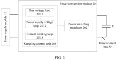
- FIG. 3 is a schematic diagram of a structure of a power conversion module according to this application.
- the power conversion module 20 shown in FIG. 2 may include a sampling control unit 201 and a power transistor 202.
- the power transistor 202 may be a bidirectional power transistor.
- the sampling control unit 201 may include a bus voltage loop 2011, a power supply voltage loop 2012, and a current limiting loop 2013.
- the power supply voltage loop 2012 is a voltage loop configured to perform maximum power point tracking (maximum power point tracking, MPPT) control on the power supply module 10.
- MPPT maximum power point tracking
- an optimal operating point of the power supply module 10 for example, the photovoltaic array
- a maximum power point for example, the photovoltaic array
- photovoltaic maximum power point tracking may be performed on the photovoltaic array by using the power supply voltage loop 2012, so that the photovoltaic array works at the maximum power point as much as possible.
- one or more functional units or hardware devices that are in the power conversion module and that have a sampling function and a control logic function may be collectively referred to as the sampling control unit.
- the sampling control unit 201 may track the maximum power point of the power supply module 10 in real time, and determine a bus reference voltage of the direct current bus 50 and a power supply reference voltage of the power supply module 10 based on the maximum power point of the power supply module 10.
- the sampling control unit 201 may determine a bus reference duty cycle based on the bus reference voltage, determine a power supply reference duty cycle based on the power supply reference voltage, and determine a current limiting reference duty cycle based on a preset current-limit value of the power conversion module 20.
- the preset current-limit value herein may be a maximum operating current value configured inside the power conversion module 20, or a maximum operating current value set by a user based on the power conversion module 20.
- the sampling control unit 201 may determine a given duty cycle of the power conversion module 20 based on the bus reference duty cycle, the power supply reference duty cycle, and the current limiting reference duty cycle, and control, based on the given duty cycle, the power transistor 202 to work, to control the direct current bus 50 to have a target bus voltage (that is, a voltage at two ends of the bus capacitor C) and enable the power conversion module 20 to run at the maximum power point.
- a target bus voltage that is, a voltage at two ends of the bus capacitor C
- an actual duty cycle used to control the power conversion module to work may be referred to as the given duty cycle.
- the target bus voltage herein may be a bus voltage value within a preset bus voltage range, to stabilize a bus voltage of the direct current bus 50.
- the power conversion module 20 can provide a stable bus voltage for the DC/AC conversion module 60, so that the DC/AC conversion module 60 provides high-quality alternating-current electrical energy for the alternating current load.
- the power supply system 1 can run at the maximum power point, so that power supply efficiency is higher and applicability is higher.
- the sampling control unit 201 may collect a current output voltage and/or a current output current of the power supply module 10 in real time based on the sampling function of the sampling control unit 201, and process the current output voltage and/or the current output current of the power supply module 10 by using a perturbation and observation method, an incremental conductance method, a current sweep method, or another manner, to obtain the maximum power point of the power supply module 10.
- the maximum power point of the power supply module 10 varies with different operating temperatures and/or illumination intensities.
- the bus reference voltage and the power supply reference voltage also vary with the maximum power point. Therefore, the bus reference voltage and the power supply reference voltage can be updated in real time by using the tracked maximum power point.
- the sampling control unit 201 may determine the bus reference voltage of the direct current bus 50 and the power supply reference voltage of the power supply module 10 based on the maximum power point of the power supply module 10 that is tracked in real time.
- the bus voltage loop 2011 may determine the bus reference duty cycle based on the bus reference voltage of the direct current bus 50.
- the bus reference duty cycle herein can be understood as a drive signal that is extracted by the bus voltage loop 2011 from the bus reference voltage and that is in direct proportion to the bus reference voltage.
- the drive signal may be a pulse width modulation (pulse width modulation, PWM) signal of a switch, and may be referred to as a PWM signal for short.
- PWM pulse width modulation
- 1 in the PWM signal may indicate turn-on of the switch, and 0 in the PWM signal may indicate turn-off of the switch.
- the bus voltage loop 2011 may be a closed-loop controller (which may also be referred to as a negative feedback controller).
- the closed-loop controller may be a proportional integral controller (proportional integral controller, which may be referred to as a PI controller for short) without a steady-state error or may be another controller.
- the PI controller herein is a linear controller.
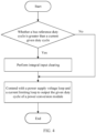
- FIG. 4 is a schematic diagram of a working procedure for a bus voltage loop according to this application. As shown in FIG. 4 , when the bus reference duty cycle is greater than the current given duty cycle of the power conversion module 20, the bus voltage loop 2011 may perform integral input clearing, so that a response speed of the system can be improved while an anti-saturation function is provided, and applicability is higher. Otherwise, when the bus reference duty cycle is less than or equal to the current given duty cycle of the power conversion module 20, the bus voltage loop 2011 may contend with the power supply voltage loop 2012 and the current limiting loop 2013 for outputting the given duty cycle of the power conversion module 20.
- the power supply voltage loop 2012 may determine the power supply reference duty cycle based on the power supply reference voltage of the power supply module 10.
- the power supply reference duty cycle herein can be understood as a drive signal that is extracted by the power supply voltage loop 2012 from the power supply reference voltage and that is in direct proportion to the power supply reference voltage.
- the drive signal is a PWM signal.
- the power supply voltage loop 2012 may be a closed-loop controller.
- the closed-loop controller is a proportional integral controller (namely, a PI controller) without a steady-state error or is another controller.
- FIG. 5 is a schematic diagram of a working procedure for a power supply voltage loop according to this application. As shown in FIG.
- the power supply voltage loop 2012 may perform integral input clearing, so that the response speed of the system can be improved while the anti-saturation function is provided, and applicability is higher. Otherwise, when the power supply reference duty cycle is less than or equal to the current given duty cycle of the power conversion module 20, the power supply voltage loop 2012 may contend with the bus voltage loop 2011 and the current limiting loop 2013 for outputting the given duty cycle of the power conversion module 20.
- the current limiting loop 2013 may determine the current limiting reference duty cycle based on the preset current-limit value of the power conversion module 20.
- the current limiting reference duty cycle herein can be understood as a drive signal that is extracted by the current limiting loop 2013 from the preset current-limit value and that is in direct proportion to the preset current-limit value.
- the drive signal is a PWM signal.
- the current limiting loop 2013 may be a closed-loop controller.
- the closed-loop controller is a proportional integral controller (namely, a PI controller) without a steady-state error or is another controller.
- FIG. 6 is a schematic diagram of a working procedure for a current limiting loop according to this application. As shown in FIG.
- the current limiting loop 2013 may perform integral input clearing, so that the response speed of the system can be improved while an anti-saturation function is provided, a current of the power conversion module is controlled to be within a safe range, and applicability is higher. Otherwise, when the current limiting reference duty cycle is less than or equal to the current given duty cycle of the power conversion module 20, the current limiting loop 2013 may contend with the bus voltage loop 2011 and the power supply voltage loop 2012 for outputting the given duty cycle of the power conversion module 20.
- the sampling control unit 201 may determine a smallest reference duty cycle from the bus reference duty cycle, the power supply reference duty cycle, and the current limiting reference duty cycle, and determine the smallest reference duty cycle as the given duty cycle of the power conversion module 20.
- the bus voltage loop 2011 outputs the given duty cycle of the power conversion module 20.
- the bus voltage loop 2011 succeeds in contention
- the power supply voltage loop 2012 and the current limiting loop 2013 fail in contention
- the sampling control unit 201 may control the power conversion module 20 to run at the maximum power point. It can be understood that, during on-grid operation or off-grid load shedding, the bus voltage loop 2011 controls the direct current bus 50. This can prevent the bus voltage of the direct current bus 50 from increasing, thereby stabilizing the bus voltage of the direct current bus 50.
- the power supply voltage loop 2012 when the smallest reference duty cycle is the power supply reference duty cycle, the power supply voltage loop 2012 outputs the given duty cycle of the power conversion module 20. In this case, the power supply voltage loop 2012 succeeds in contention, and the bus voltage loop 2011 and the current limiting loop 2013 fail in contention. It can be understood that, when the bus voltage is reduced during off-grid, the bus voltage loop 2011 fails in contention. In this case, the power supply voltage loop 2012 outputs the given duty cycle of the power conversion module 20 and continues to track the maximum power point of the power supply module 10, and a positive feedback is not formed in the bus voltage loop 2011. This stabilizes the bus voltage of the direct current bus 50 and improves system stability.
- the current limiting loop 2013 when the smallest reference duty cycle is the current limiting reference duty cycle, the current limiting loop 2013 outputs the given duty cycle of the power conversion module 20. In this case, the current limiting loop 2013 succeeds in contention, the bus voltage loop 2011 and the power supply voltage loop 2012 fail in contention, and the sampling control unit 201 may control the power conversion module 20 to run at the maximum power point. It can be understood that, in a case in which the bus reference duty cycle is greater than the current limiting reference duty cycle and the power supply reference duty cycle is greater than the current limiting reference duty cycle, to ensure that overcurrent does not occur in a system current, the sampling control unit 201 may control the current limiting loop 2013 to output the given duty cycle of the power conversion module 20, and applicability is higher.
- the sampling control unit 201 may control the power conversion module 20 to run at the maximum power point. In other words, the sampling control unit 201 may control the power conversion module 20 to run at the maximum power point when the power supply voltage loop 2012 fails in contention.
- FIG. 7 is a schematic diagram of a working procedure for a power conversion module according to this application.
- a bus voltage loop 2011 may determine a bus reference duty cycle (for example, which may be represented as D bus_ref ) based on a bus reference voltage (for example, which may be represented as U bus_ref ).
- a power supply voltage loop 2012 may determine a power supply reference duty cycle (for example, which may be represented as D pv_ref ) based on a power supply reference voltage (for example, which may be represented as U pv_ref ).
- a current limiting loop 2013 may determine a current limiting reference duty cycle (for example, which may be represented as D i_ref ) based on a preset current-limit value (for example, which may be represented as I limit ).
- a sampling control unit 201 may determine, as a given duty cycle (for example, which may be represented as D ref ) of the power conversion module 20, a smallest duty cycle among the bus reference duty cycle D bus_ref , the power supply reference duty cycle D pv_ref , and the current limiting reference duty cycle D i_ref , and control, based on the given duty cycle D ref , a power transistor 202 to work.
- the power transistor 202 may be an insulated gate bipolar transistor (insulated gate bipolar transistor, which may be referred to as IGBT for short), a metal-oxide-semiconductor field-effect transistor (metal-oxide-semiconductor field-effect transistor, which may be referred to as MOSFET for short), or a diode made of a silicon (silicon, Si) semiconductor material, a third-generation wide bandgap semiconductor material such as silicon carbide (silicon carbide, SiC), gallium nitride (gallium nitride, GaN), diamond (diamond), or zinc oxide (zinc oxide, ZnO), or made of another material.
- IGBT insulated gate bipolar transistor
- MOSFET metal-oxide-semiconductor field-effect transistor
- FIG. 8 is a schematic diagram of a circuit of a power conversion module according to this application.
- the power conversion module 20 may include a filter inductor L, a diode D, and a power transistor 202, and the power transistor 202 includes a switch S (the switch S is an IGBT).
- One end of the filter inductor L is connected to a power supply module 10, the other end of the filter inductor L is connected to one end of the diode D and a collector of the switch S, an emitter of the switch S is connected to one end of the power supply module 10 and one end of a bus capacitor C, a base of the switch S may be connected to a sampling control unit 201, and the other end of the bus capacitor C is connected to the other end of the diode D.
- the bus capacitor C herein can be understood as an output capacitor of the power conversion module 20.
- the sampling control unit 201 may control, based on the given duty cycle, the switch S to work, to stabilize a bus voltage of a direct current bus 50 and enable the power conversion module 20 to run at a maximum power point.
- the power conversion module 20 can provide a stable bus voltage for a DC/AC conversion module 60, so that the DC/AC conversion module 60 provides high-quality alternating-current electrical energy for an alternating current load.
- a power supply system 1 can run at the maximum power point, so that power supply efficiency is higher and applicability is higher.
- an off-grid mode and an on-grid mode may be unified, so that the bus voltage loop, the power supply voltage loop, and the current limiting loop are run in parallel, to reduce complex mode switching.
- loop contention may be performed to stabilize the bus voltage of the direct current bus and implement maximum power point tracking, so that system stability is improved, the response speed of the system is fast, and applicability is higher.
Landscapes
- Engineering & Computer Science (AREA)
- Power Engineering (AREA)
- Dc-Dc Converters (AREA)
- Emergency Protection Circuit Devices (AREA)
- Prostheses (AREA)
Abstract
Description
- This application claims priority to
Chinese Patent Application No. 202110200485.9, filed with the China National Intellectual Property Administration on February 23, 2021 - This application relates to the field of electric power technologies, and in particular, to a power conversion module and a power supply system.
- In a pure photovoltaic system or a photovoltaic system provided with energy storage, when the photovoltaic system runs off grid to supply power to a load, an energy storage battery or a photovoltaic unidirectional direct current (direct current, DC)/DC conversion module runs in a voltage source mode to provide a stable direct current bus voltage for the photovoltaic system. This ensures that the DC/alternating current (direct current, AC) conversion module can run normally to provide a high-quality alternating current voltage for the load. When the energy storage battery is in an offline state (for example, battery energy is insufficient, the energy storage battery is powered off or faulty, or no energy storage battery is configured), only the photovoltaic unidirectional DC/DC conversion module can provide a bus voltage. However, due to the special characteristics of a photovoltaic curve, when the system runs on a left side of a maximum power point, a bus is out of control, and consequently the system crashes and breaks down.
- During research and practice, the inventor of this application finds that in the conventional technology, current limiting may be performed on a bus voltage loop to prevent the system from running on the left side of the maximum power point. However, a current at the maximum power point cannot be accurately determined because of a change of illumination. As a result, when a current-limit value of the bus voltage loop is less than the current at the maximum power point, the system cannot run to the maximum power point, causing a waste of energy; or when a current-limit value of the bus voltage loop is greater than the current of the maximum power point, the photovoltaic system still runs on the left side of the maximum power point because of a load change, causing the bus to be out of control. In addition, in the conventional technology, it may be further determined in real time whether the photovoltaic system runs on the left side of the maximum power point, and when the system runs on the left side of the maximum power point, current limiting is performed on a maximum current of the system and the bus voltage loop is controlled again. However, this causes system power to fluctuate repeatedly, and causes low stability.
- This application provides a power conversion module and a power supply system, to stabilize a direct current bus and control the power conversion module to run at a maximum power point, so that system stability is improved and applicability is high.
- According to a first aspect, this application provides a power conversion module. The power conversion module is applicable to a power supply system, the power supply system further includes a power supply module and a direct current bus, the power supply module may be connected in parallel to the direct current bus by using the power conversion module, and the power conversion module may include a power transistor and a sampling control unit. The sampling control unit may be configured to: track a maximum power point of the power supply module, and determine a bus reference voltage of the direct current bus and a power supply reference voltage of the power supply module based on the maximum power point of the power supply module, so that the bus reference voltage and the power supply reference voltage can be updated in real time by using the tracked maximum power point. The sampling control unit is further configured to: determine a bus reference duty cycle based on the bus reference voltage, determine a power supply reference duty cycle based on the power supply reference voltage, and determine a current limiting reference duty cycle based on a preset current-limit value of the power conversion module. The sampling control unit is configured to: determine a given duty cycle of the power conversion module based on the bus reference duty cycle, the power supply reference duty cycle, and the current limiting reference duty cycle, and control, based on the given duty cycle, the power transistor to work, to control the direct current bus to have a target bus voltage and enable the power conversion module to run at the maximum power point. In this application, an off-grid mode and an on-grid mode may be unified, to reduce complex mode switching. In addition, the given duty cycle of the power conversion module may be determined based on the bus reference duty cycle, the power supply reference duty cycle, and the current limiting reference duty cycle, to stabilize a bus voltage of the direct current bus and implement maximum power point tracking, so that system stability is improved and applicability is higher.
- With reference to the first aspect, in a first possible implementation, the sampling control unit includes a bus voltage loop, a power supply voltage loop, and a current limiting loop, where the power supply voltage loop is a voltage loop configured to perform maximum power point tracking control on the power supply module. The bus voltage loop may be configured to determine the bus reference duty cycle based on the bus reference voltage of the direct current bus. The power supply voltage loop may be configured to determine the power supply reference duty cycle based on the power supply reference voltage of the power supply module. The current limiting loop is configured to determine the current limiting reference duty cycle based on the preset current-limit value of the power conversion module. In the power conversion module provided in this application, the off-grid mode and the on-grid mode may be unified, so that the bus voltage loop, the power supply voltage loop, and the current limiting loop are run in parallel, to reduce complex mode switching. In addition, the bus voltage loop, the power supply voltage loop, and the current limiting loop may directly determine the bus reference duty cycle, the power supply reference duty cycle, and the current limiting reference duty cycle, so that a response speed of the system is fast and applicability is higher.
- With reference to the first possible implementation of the first aspect, in a second possible implementation, the sampling control unit is configured to determine, as the given duty cycle of the power conversion module, a smallest reference duty cycle among the bus reference duty cycle, the power supply reference duty cycle, and the current limiting reference duty cycle. When the smallest reference duty cycle is the bus reference duty cycle, the bus voltage loop outputs the given duty cycle of the power conversion module. It can be understood that, during on-grid operation or off-grid load shedding, the bus voltage loop controls the direct current bus. This can prevent the bus voltage of the direct current bus from increasing, thereby stabilizing the bus voltage of the direct current bus. When the smallest reference duty cycle is the power supply reference duty cycle, the power supply voltage loop outputs the given duty cycle of the power conversion module. It can be understood that, when the bus voltage is reduced during off-grid, the bus voltage loop fails in contention. In this case, the power supply voltage loop outputs the given duty cycle of the power conversion module, and a positive feedback is not formed in the bus voltage loop. This stabilizes the bus voltage of the direct current bus and improves system stability. When the smallest reference duty cycle is the current limiting reference duty cycle, the current limiting loop outputs the given duty cycle of the power conversion module. In this way, that overcurrent does not occur in a system current is ensured, and applicability is higher. In the power conversion module provided in this application, the bus voltage loop, the power supply voltage loop, and the current limiting loop may perform loop contention to stabilize the bus voltage of the direct current bus and implement maximum power point tracking, so that system stability is improved and applicability is higher.
- With reference to the second possible implementation of the first aspect, in a third possible implementation, the sampling control unit is further configured to: when determining the bus reference duty cycle or the current limiting reference duty cycle as the given duty cycle of the power conversion module, control the power conversion module to run at the maximum power point. It can be understood that, when determining the bus reference duty cycle or the current limiting reference duty cycle as the given duty cycle of the power conversion module, the sampling control unit may determine that the power supply voltage loop fails in contention. In the power conversion module provided in this application, when the power supply voltage loop fails in contention, the power conversion module may be controlled to run at the maximum power point, so that the response speed of the system is fast and applicability is higher.
- With reference to any one of the first possible implementation of the first aspect to the third possible implementation of the first aspect, in a fourth possible implementation, the bus voltage loop is a closed-loop controller, and the closed-loop controller is a proportional integral controller without a steady-state error or is another controller. The bus voltage loop is further configured to perform integral input clearing when the bus reference duty cycle is greater than the current given duty cycle of the power conversion module. In other words, when the bus reference duty cycle is greater than the current given duty cycle of the power conversion module, the bus voltage loop fails in contention and performs integral input clearing, so that the response speed of the system can be improved while an anti-saturation function is provided, and applicability is higher.
- With reference to any one of the first possible implementation of the first aspect to the fourth possible implementation of the first aspect, in a fifth possible implementation, the power supply voltage loop is a closed-loop controller, and the closed-loop controller is a proportional integral controller without a steady-state error or is another controller. The power supply voltage loop is further configured to perform integral input clearing when the power supply reference duty cycle is greater than the current given duty cycle of the power conversion module. In other words, when the power supply reference duty cycle is greater than the current given duty cycle of the power conversion module, the power supply voltage loop fails in contention and performs integral input clearing, so that the response speed of the system can be improved while the anti-saturation function is provided, and applicability is higher.
- With reference to any one of the first possible implementation of the first aspect to the fifth possible implementation of the first aspect, in a sixth possible implementation, the current limiting loop is a closed-loop controller, and the closed-loop controller is a proportional integral controller without a steady-state error or is another controller. The current limiting loop is further configured to perform integral input clearing when the current limiting reference duty cycle is greater than the current given duty cycle of the power conversion module. In other words, when the current limiting reference duty cycle is greater than the current given duty cycle of the power conversion module, the current limiting loop fails in contention and performs integral input clearing, so that the response speed of the system can be improved while the anti-saturation function is provided, a current of the power conversion module is controlled to be within a safe range, and applicability is higher.
- According to a second aspect, this application provides a power supply system. The power supply system includes a power supply module, an energy storage module, a direct current DC/DC conversion module, a direct current bus, a direct current DC/alternating current AC conversion module, an on/off grid connection box, and the power conversion module provided in any one of the first aspect to the sixth possible implementation of the first aspect. The power supply module is connected in parallel to the direct current bus by using the power conversion module, the energy storage module is connected in parallel to the direct current bus by using the DC/DC conversion module, one end of the DC/AC conversion module is connected in parallel to the direct current bus, and the other end of the DC/AC conversion module is connected to an alternating current load or an alternating current power grid by using the on/off grid connection box. The power conversion module is configured to: convert electrical energy provided by the power supply module into direct-current electrical energy, and output the direct-current electrical energy to the DC/AC converter. The DC/DC conversion module is configured to convert direct-current electrical energy provided by the energy storage module into target direct-current electrical energy, and output the target direct-current electrical energy to the DC/AC conversion module. The DC/AC conversion module is configured to: convert the direct-current electrical energy that is input by the power conversion module and the target direct-current electrical energy that is input by the DC/DC conversion module into alternating-current electrical energy, and supply power to the alternating current load or the alternating current power grid by using the on/off grid connection box. In this application, after the power conversion module performs loop contention to stabilize a bus voltage of the direct current bus and implement maximum power point tracking, a stable direct current bus voltage can be provided for the DC/AC conversion module, and the power supply system runs at the maximum power point, so that power supply efficiency is higher and applicability is higher.
- With reference to the second aspect, in a first possible implementation, in a hybrid photovoltaic and energy-storage power supply scenario, the power supply module is a photovoltaic array, and the power conversion module is a DC/DC conversion module.
- With reference to the second aspect, in a second possible implementation, in a hybrid wind and energy-storage power supply scenario, the power supply module is a generator, and the power conversion module is an AC/DC conversion module.
- In this application, an off-grid mode and an on-grid mode may be unified, to reduce complex mode switching. In addition, the given duty cycle of the power conversion module may be determined based on the bus reference duty cycle, the power supply reference duty cycle, and the current limiting reference duty cycle, to stabilize the bus voltage of the direct current bus and implement maximum power point tracking, so that system stability is improved and applicability is higher.
-
-
FIG. 1 is a schematic diagram of an application scenario of a power supply system according to this application; -
FIG. 2 is a schematic diagram of a structure of a power supply system according to this application; -
FIG. 3 is a schematic diagram of a structure of a power conversion module according to this application; -
FIG. 4 is a schematic diagram of a working procedure for a bus voltage loop according to this application; -
FIG. 5 is a schematic diagram of a working procedure for a power supply voltage loop according to this application; -
FIG. 6 is a schematic diagram of a working procedure for a current limiting loop according to this application; -
FIG. 7 is a schematic diagram of a working procedure for a power conversion module according to this application; and -
FIG. 8 is a schematic diagram of a circuit of a power conversion module according to this application. - New energy (new energy, NE, also referred to as unconventional energy) has wide functions in people's life and work. One of the functions is to convert new energy into electrical energy. The new energy may include solar energy, geothermal energy, wind energy, marine energy, biomass energy, or other new energy. A power supply system provided in this application may be a hybrid power supply system based on new energy power generation and different types of energy storage modules. The new energy power generation may include solar power generation (for example, solar photovoltaic power generation or solar photothermal power generation), geothermal power generation, wind power generation, marine power generation (for example, wave power generation or tidal power generation), and biomass power generation. The new energy power generation has no moving parts, no noise, no pollution, high reliability, and other characteristics, and has excellent application prospects for communication power supply systems in remote regions. Components in different types of energy storage modules herein may include a lithium-ion battery, a lead-acid battery (or referred to as a lead-acid storage battery), a supercapacitor (or referred to as an electrochemical capacitor), and the like. Specific types of the components in the energy storage modules are not limited in this application. The power supply system provided in this application may be applicable to a plurality of types of power generation devices, such as base station equipment in a remote region with no mains supply or a poor mains supply, a photovoltaic power generation device, or a wind power generation device, or may be applicable to another electrical device (for example, a power grid, a household device, or an industrial and commercial electrical device). An application scope of the power supply system may be specifically determined based on an actual application scenario, and is not limited herein.
- The power supply system provided in this application may include a power supply module, an energy storage module, a direct current DC/DC conversion module (which may also be referred to as a DC/DC converter), a direct current bus, a direct current DC/alternating current AC conversion module (which may also be referred to as a DC/AC converter), an on/off grid connection box, and a power conversion module. The power supply module is connected in parallel to the direct current bus by using the power conversion module, the energy storage module is connected in parallel to the direct current bus by using the DC/DC conversion module, one end of the DC/AC conversion module is connected in parallel to the direct current bus, and the other end of the DC/AC conversion module is connected to an alternating current load or an alternating current power grid by using the on/off grid connection box. The energy storage module herein may include at least one battery cluster, and the battery clusters are connected in parallel. The power conversion module may convert electrical energy provided by the power supply module into direct-current electrical energy, and output the direct-current electrical energy to the DC/AC converter. The DC/DC conversion module may convert direct-current electrical energy provided by the energy storage module into target direct-current electrical energy, and output the target direct-current electrical energy to the DC/AC conversion module. The DC/AC conversion module may convert the direct-current electrical energy that is input by the power conversion module and the target direct-current electrical energy that is input by the DC/DC conversion module into alternating-current electrical energy, and supply power to the alternating current load or the alternating current power grid by using the on/off grid connection box. The following uses a hybrid photovoltaic and energy-storage power supply scenario as an example for description. Details are not described below again.
-
FIG. 1 is a schematic diagram of an application scenario of a power supply system according to this application. In a hybrid photovoltaic and energy-storage power supply scenario, a power supply module is a photovoltaic array, and the foregoing power conversion module is a DC/DC conversion module (which may also be referred to as a DC/DC converter). As shown inFIG. 1 , the power supply system (for example, a power supply system 1) may include a photovoltaic power supply device, an energy storage container, and a DC/AC converter. The photovoltaic power supply device may include a photovoltaic array and the DC/DC converter. The photovoltaic array may include a plurality of photovoltaic module strings connected in parallel. A photovoltaic module may also be referred to as a solar panel or a photovoltaic panel. The energy storage container herein may include at least one battery cluster and a DC/DC converter, the battery clusters are connected in parallel, and one battery cluster may include a plurality of battery strings connected in series. The battery string may be a battery pack, and one battery pack may include one battery unit or a plurality of battery units (a voltage of the battery unit is usually between 2.5 V and 4.2 V) connected in series and in parallel, to form a smallest energy storage and management unit. After thepower supply system 1 starts to work, in the photovoltaic power supply device, the photovoltaic array may convert solar energy into electrical energy (that is, direct-current electrical energy), and output the electrical energy to the DC/DC converter. The DC/DC converter may convert the electrical energy input by the photovoltaic array into direct-current electrical energy, and output the direct-current electrical energy to the DC/AC converter. In this way, the photovoltaic power supply device outputs the direct-current electrical energy to the DC/AC converter. In the energy storage container, each of the at least one battery cluster may output direct-current electrical energy to the DC/DC converter, and the DC/DC converter may convert the direct-current electrical energy input by each battery cluster into target direct-current electrical energy and output the target direct-current electrical energy to the DC/AC converter. In this way, the energy storage container outputs the target direct-current electrical energy to the DC/AC converter. In this case, the DC/AC converter may convert the direct-current electrical energy input by the photovoltaic power supply device and the target direct-current electrical energy input by the energy storage container into alternating-current electrical energy, and output the alternating-current electrical energy to an alternating current power grid (for example, a power grid 2) or an alternating current load (for example, a household device 3), to supply power to thepower grid 2 or the household device 3. - With reference to
FIG. 2 to FIG. 8 , the following describes the power supply system and the power conversion module that are provided in this application and working principles of the power supply system and the power conversion module by using examples. -
FIG. 2 is a schematic diagram of a structure of a power supply system according to this application. As shown inFIG. 2 , thepower supply system 1 may include apower supply module 10, apower conversion module 20, anenergy storage module 30, a DC/DC conversion module 40, a direct current bus 50, a DC/AC conversion module 60, and an on/offgrid connection box 70. Thepower supply module 10 may be connected in parallel to the direct current bus 50 by using thepower conversion module 20, theenergy storage module 30 is connected in parallel to the direct current bus 50 by using the DC/DC conversion module 40, one end of the DC/AC conversion module 60 is connected in parallel to the direct current bus 50, and the other end of the DC/AC conversion module 60 is connected to an alternating current load or an alternating current power grid by using the on/offgrid connection box 70. Thepower conversion module 20 herein may be an AC/DC conversion module or a unidirectional DC/DC conversion module, and a circuit topology of thepower conversion module 20 may be a bootstrap circuit (bootstrap circuit, which may be referred to as a BST circuit for short, or may be referred to as a boost circuit). Therefore, the power conversion module may also be referred to as a BST conversion module or a BST converter. The foregoing DC/DC conversion module 40 may be a bidirectional DC/DC conversion module. Optionally, the direct current bus 50 may include one bus capacitor or a plurality of bus capacitors connected in series. For example, as shown inFIG. 2 , the direct current bus 50 includes a bus capacitor C. - In some feasible implementations, in a hybrid photovoltaic and energy-storage power supply scenario, the
power supply module 10 may be a photovoltaic array, and thepower conversion module 20 may be a unidirectional DC/DC conversion module. The photovoltaic array may convert solar energy into electrical energy (that is, direct-current electrical energy), and output the electrical energy to the unidirectional DC/DC conversion module. The unidirectional DC/DC conversion module may convert the electrical energy input by the photovoltaic array into direct-current electrical energy, and output the direct-current electrical energy to the DC/AC conversion module 60. Theenergy storage module 30 may output direct-current electrical energy to the DC/DC conversion module 40. The DC/DC conversion module 40 may convert the direct-current electrical energy input by theenergy storage module 30 into target direct-current electrical energy, and output the target direct-current electrical energy to the DC/AC conversion module 60. Further, the DC/AC conversion module 60 may convert the direct-current electrical energy input by the unidirectional DC/DC conversion module and the target direct-current electrical energy input by the DC/DC conversion module 40 into alternating-current electrical energy, and output the alternating-current electrical energy to the alternating current power grid or the alternating current load by using the on/offgrid connection box 70, to supply power to the alternating current power grid or the alternating current load. - In some feasible implementations, in a hybrid wind and energy-storage power supply scenario, the
power supply module 10 is a generator, and thepower conversion module 20 is an AC/DC conversion module (which may also be referred to as an AC/DC converter). The generator may convert wind energy into alternating-current electrical energy, and output the alternating-current electrical energy to the AC/DC conversion module. The AC/DC conversion module may convert the alternating-current electrical energy input by the generator into direct-current electrical energy, and output the direct-current electrical energy to the DC/AC conversion module 60. Theenergy storage module 30 may output direct-current electrical energy to the DC/DC conversion module 40. The DC/DC conversion module 40 may convert the direct-current electrical energy input by theenergy storage module 30 into target direct-current electrical energy, and output the target direct-current electrical energy to the DC/AC conversion module 60. Further, the DC/AC conversion module 60 may convert the direct-current electrical energy input by the AC/DC conversion module and the target direct-current electrical energy input by the DC/DC conversion module 40 into alternating-current electrical energy, and output the alternating-current electrical energy to the alternating current power grid or the alternating current load by using the on/offgrid connection box 70, to supply power to the alternating current power grid or the alternating current load. - In some feasible implementations, when the alternating current power grid is powered off or the
power supply system 1 runs off grid to supply power to the alternating current load, the DC/AC conversion module 60 needs to provide high-quality alternating-current electrical energy for the alternating current load. In this case, thepower conversion module 20 or the DC/DC conversion module 40 runs in a voltage source mode to provide a stable bus voltage (that is, a direct current bus voltage) for the DC/AC conversion module 60. This ensures that the DC/AC conversion module 60 runs normally to provide the high-quality alternating-current electrical energy for the alternating current load. Optionally, when noenergy storage module 30 is configured in thepower supply system 1, energy of theenergy storage module 30 is insufficient, theenergy storage module 30 is powered off, or theenergy storage module 30 is faulty, it may indicate that theenergy storage module 30 is in an offline state. In this case, thepower conversion module 20 runs in a voltage source mode to provide a stable bus voltage for the DC/AC conversion module 60. In addition, to prevent thepower supply system 1 from running on a left side of a maximum power point, causing the direct current bus 50 to be out of control, thepower conversion module 20 needs to run at the maximum power point. It can be learned that, when the alternating current power grid is powered off, thepower supply system 1 runs off grid to supply power to the alternating current load, or theenergy storage module 30 is in the offline state, thepower conversion module 20 needs to run at the maximum power point and provide a stable bus voltage for the DC/AC conversion module 60. - Further, refer to
FIG. 3. FIG. 3 is a schematic diagram of a structure of a power conversion module according to this application. As shown inFIG. 3 , thepower conversion module 20 shown inFIG. 2 may include asampling control unit 201 and apower transistor 202. Thepower transistor 202 may be a bidirectional power transistor. Thesampling control unit 201 may include abus voltage loop 2011, a powersupply voltage loop 2012, and a current limitingloop 2013. The powersupply voltage loop 2012 is a voltage loop configured to perform maximum power point tracking (maximum power point tracking, MPPT) control on thepower supply module 10. In this application, an optimal operating point of the power supply module 10 (for example, the photovoltaic array) may be referred to as a maximum power point. For ease of description, the following uses the photovoltaic array as an example for description. Because the maximum power point of the photovoltaic array mainly depends on an operating temperature and an illumination intensity of the photovoltaic array, and the maximum power point of the photovoltaic array varies with different operating temperatures and illumination intensities, photovoltaic maximum power point tracking may be performed on the photovoltaic array by using the powersupply voltage loop 2012, so that the photovoltaic array works at the maximum power point as much as possible. In this application, one or more functional units or hardware devices that are in the power conversion module and that have a sampling function and a control logic function may be collectively referred to as the sampling control unit. - In some feasible implementations, the
sampling control unit 201 may track the maximum power point of thepower supply module 10 in real time, and determine a bus reference voltage of the direct current bus 50 and a power supply reference voltage of thepower supply module 10 based on the maximum power point of thepower supply module 10. Thesampling control unit 201 may determine a bus reference duty cycle based on the bus reference voltage, determine a power supply reference duty cycle based on the power supply reference voltage, and determine a current limiting reference duty cycle based on a preset current-limit value of thepower conversion module 20. The preset current-limit value herein may be a maximum operating current value configured inside thepower conversion module 20, or a maximum operating current value set by a user based on thepower conversion module 20. This may be specifically determined based on an actual application scenario, and is not limited herein. Further, thesampling control unit 201 may determine a given duty cycle of thepower conversion module 20 based on the bus reference duty cycle, the power supply reference duty cycle, and the current limiting reference duty cycle, and control, based on the given duty cycle, thepower transistor 202 to work, to control the direct current bus 50 to have a target bus voltage (that is, a voltage at two ends of the bus capacitor C) and enable thepower conversion module 20 to run at the maximum power point. In this application, an actual duty cycle used to control the power conversion module to work may be referred to as the given duty cycle. The target bus voltage herein may be a bus voltage value within a preset bus voltage range, to stabilize a bus voltage of the direct current bus 50. In this case, thepower conversion module 20 can provide a stable bus voltage for the DC/AC conversion module 60, so that the DC/AC conversion module 60 provides high-quality alternating-current electrical energy for the alternating current load. In addition, when thepower conversion module 20 runs at the maximum power point, thepower supply system 1 can run at the maximum power point, so that power supply efficiency is higher and applicability is higher. - In some feasible implementations, the
sampling control unit 201 may collect a current output voltage and/or a current output current of thepower supply module 10 in real time based on the sampling function of thesampling control unit 201, and process the current output voltage and/or the current output current of thepower supply module 10 by using a perturbation and observation method, an incremental conductance method, a current sweep method, or another manner, to obtain the maximum power point of thepower supply module 10. It can be understood that, the maximum power point of thepower supply module 10 varies with different operating temperatures and/or illumination intensities. In this case, the bus reference voltage and the power supply reference voltage also vary with the maximum power point. Therefore, the bus reference voltage and the power supply reference voltage can be updated in real time by using the tracked maximum power point. For example, when the maximum power point increases, the bus reference voltage and the power supply reference voltage also increase. Further, thesampling control unit 201 may determine the bus reference voltage of the direct current bus 50 and the power supply reference voltage of thepower supply module 10 based on the maximum power point of thepower supply module 10 that is tracked in real time. - In some feasible implementations, the
bus voltage loop 2011 may determine the bus reference duty cycle based on the bus reference voltage of the direct current bus 50. The bus reference duty cycle herein can be understood as a drive signal that is extracted by thebus voltage loop 2011 from the bus reference voltage and that is in direct proportion to the bus reference voltage. For example, the drive signal may be a pulse width modulation (pulse width modulation, PWM) signal of a switch, and may be referred to as a PWM signal for short. For example, 1 in the PWM signal may indicate turn-on of the switch, and 0 in the PWM signal may indicate turn-off of the switch. Thebus voltage loop 2011 may be a closed-loop controller (which may also be referred to as a negative feedback controller). The closed-loop controller may be a proportional integral controller (proportional integral controller, which may be referred to as a PI controller for short) without a steady-state error or may be another controller. The PI controller herein is a linear controller.FIG. 4 is a schematic diagram of a working procedure for a bus voltage loop according to this application. As shown inFIG. 4 , when the bus reference duty cycle is greater than the current given duty cycle of thepower conversion module 20, thebus voltage loop 2011 may perform integral input clearing, so that a response speed of the system can be improved while an anti-saturation function is provided, and applicability is higher. Otherwise, when the bus reference duty cycle is less than or equal to the current given duty cycle of thepower conversion module 20, thebus voltage loop 2011 may contend with the powersupply voltage loop 2012 and the current limitingloop 2013 for outputting the given duty cycle of thepower conversion module 20. - In some feasible implementations, the power
supply voltage loop 2012 may determine the power supply reference duty cycle based on the power supply reference voltage of thepower supply module 10. The power supply reference duty cycle herein can be understood as a drive signal that is extracted by the powersupply voltage loop 2012 from the power supply reference voltage and that is in direct proportion to the power supply reference voltage. For example, the drive signal is a PWM signal. The powersupply voltage loop 2012 may be a closed-loop controller. The closed-loop controller is a proportional integral controller (namely, a PI controller) without a steady-state error or is another controller.FIG. 5 is a schematic diagram of a working procedure for a power supply voltage loop according to this application. As shown inFIG. 5 , when the power supply reference duty cycle is greater than the current given duty cycle of thepower conversion module 20, the powersupply voltage loop 2012 may perform integral input clearing, so that the response speed of the system can be improved while the anti-saturation function is provided, and applicability is higher. Otherwise, when the power supply reference duty cycle is less than or equal to the current given duty cycle of thepower conversion module 20, the powersupply voltage loop 2012 may contend with thebus voltage loop 2011 and the current limitingloop 2013 for outputting the given duty cycle of thepower conversion module 20. - In some feasible implementations, the current limiting
loop 2013 may determine the current limiting reference duty cycle based on the preset current-limit value of thepower conversion module 20. The current limiting reference duty cycle herein can be understood as a drive signal that is extracted by the current limitingloop 2013 from the preset current-limit value and that is in direct proportion to the preset current-limit value. For example, the drive signal is a PWM signal. The current limitingloop 2013 may be a closed-loop controller. The closed-loop controller is a proportional integral controller (namely, a PI controller) without a steady-state error or is another controller.FIG. 6 is a schematic diagram of a working procedure for a current limiting loop according to this application. As shown inFIG. 6 , when the current limiting reference duty cycle is greater than the current given duty cycle of thepower conversion module 20, the current limitingloop 2013 may perform integral input clearing, so that the response speed of the system can be improved while an anti-saturation function is provided, a current of the power conversion module is controlled to be within a safe range, and applicability is higher. Otherwise, when the current limiting reference duty cycle is less than or equal to the current given duty cycle of thepower conversion module 20, the current limitingloop 2013 may contend with thebus voltage loop 2011 and the powersupply voltage loop 2012 for outputting the given duty cycle of thepower conversion module 20. - In some feasible implementations, the
sampling control unit 201 may determine a smallest reference duty cycle from the bus reference duty cycle, the power supply reference duty cycle, and the current limiting reference duty cycle, and determine the smallest reference duty cycle as the given duty cycle of thepower conversion module 20. When the smallest reference duty cycle is the bus reference duty cycle, thebus voltage loop 2011 outputs the given duty cycle of thepower conversion module 20. In this case, thebus voltage loop 2011 succeeds in contention, the powersupply voltage loop 2012 and the current limitingloop 2013 fail in contention, and thesampling control unit 201 may control thepower conversion module 20 to run at the maximum power point. It can be understood that, during on-grid operation or off-grid load shedding, thebus voltage loop 2011 controls the direct current bus 50. This can prevent the bus voltage of the direct current bus 50 from increasing, thereby stabilizing the bus voltage of the direct current bus 50. - In some feasible implementations, when the smallest reference duty cycle is the power supply reference duty cycle, the power
supply voltage loop 2012 outputs the given duty cycle of thepower conversion module 20. In this case, the powersupply voltage loop 2012 succeeds in contention, and thebus voltage loop 2011 and the current limitingloop 2013 fail in contention. It can be understood that, when the bus voltage is reduced during off-grid, thebus voltage loop 2011 fails in contention. In this case, the powersupply voltage loop 2012 outputs the given duty cycle of thepower conversion module 20 and continues to track the maximum power point of thepower supply module 10, and a positive feedback is not formed in thebus voltage loop 2011. This stabilizes the bus voltage of the direct current bus 50 and improves system stability. - In some feasible implementations, when the smallest reference duty cycle is the current limiting reference duty cycle, the current limiting
loop 2013 outputs the given duty cycle of thepower conversion module 20. In this case, the current limitingloop 2013 succeeds in contention, thebus voltage loop 2011 and the powersupply voltage loop 2012 fail in contention, and thesampling control unit 201 may control thepower conversion module 20 to run at the maximum power point. It can be understood that, in a case in which the bus reference duty cycle is greater than the current limiting reference duty cycle and the power supply reference duty cycle is greater than the current limiting reference duty cycle, to ensure that overcurrent does not occur in a system current, thesampling control unit 201 may control the current limitingloop 2013 to output the given duty cycle of thepower conversion module 20, and applicability is higher. It can be learned that, when determining the bus reference duty cycle or the current limiting reference duty cycle as the given duty cycle of thepower conversion module 20, thesampling control unit 201 may control thepower conversion module 20 to run at the maximum power point. In other words, thesampling control unit 201 may control thepower conversion module 20 to run at the maximum power point when the powersupply voltage loop 2012 fails in contention. -
FIG. 7 is a schematic diagram of a working procedure for a power conversion module according to this application. As shown inFIG. 7 , abus voltage loop 2011 may determine a bus reference duty cycle (for example, which may be represented as Dbus_ref ) based on a bus reference voltage (for example, which may be represented as Ubus_ref ). A powersupply voltage loop 2012 may determine a power supply reference duty cycle (for example, which may be represented as Dpv_ref ) based on a power supply reference voltage (for example, which may be represented as Upv_ref ). A current limitingloop 2013 may determine a current limiting reference duty cycle (for example, which may be represented as Di_ref ) based on a preset current-limit value (for example, which may be represented as I limit). In this case, asampling control unit 201 may determine, as a given duty cycle (for example, which may be represented as Dref ) of thepower conversion module 20, a smallest duty cycle among the bus reference duty cycle Dbus_ref , the power supply reference duty cycle Dpv_ref , and the current limiting reference duty cycle Di_ref , and control, based on the given duty cycle Dref , apower transistor 202 to work. - In some feasible implementations, the
power transistor 202 may be an insulated gate bipolar transistor (insulated gate bipolar transistor, which may be referred to as IGBT for short), a metal-oxide-semiconductor field-effect transistor (metal-oxide-semiconductor field-effect transistor, which may be referred to as MOSFET for short), or a diode made of a silicon (silicon, Si) semiconductor material, a third-generation wide bandgap semiconductor material such as silicon carbide (silicon carbide, SiC), gallium nitride (gallium nitride, GaN), diamond (diamond), or zinc oxide (zinc oxide, ZnO), or made of another material. This may be specifically determined based on an actual application scenario, and is not limited herein.FIG. 8 is a schematic diagram of a circuit of a power conversion module according to this application. As shown inFIG. 8 , thepower conversion module 20 may include a filter inductor L, a diode D, and apower transistor 202, and thepower transistor 202 includes a switch S (the switch S is an IGBT). One end of the filter inductor L is connected to apower supply module 10, the other end of the filter inductor L is connected to one end of the diode D and a collector of the switch S, an emitter of the switch S is connected to one end of thepower supply module 10 and one end of a bus capacitor C, a base of the switch S may be connected to asampling control unit 201, and the other end of the bus capacitor C is connected to the other end of the diode D. The bus capacitor C herein can be understood as an output capacitor of thepower conversion module 20. After determining a given duty cycle of thepower conversion module 20, thesampling control unit 201 may control, based on the given duty cycle, the switch S to work, to stabilize a bus voltage of a direct current bus 50 and enable thepower conversion module 20 to run at a maximum power point. In this case, thepower conversion module 20 can provide a stable bus voltage for a DC/AC conversion module 60, so that the DC/AC conversion module 60 provides high-quality alternating-current electrical energy for an alternating current load. In addition, when thepower conversion module 20 runs at the maximum power point, apower supply system 1 can run at the maximum power point, so that power supply efficiency is higher and applicability is higher. - In this application, an off-grid mode and an on-grid mode may be unified, so that the bus voltage loop, the power supply voltage loop, and the current limiting loop are run in parallel, to reduce complex mode switching. In addition, loop contention may be performed to stabilize the bus voltage of the direct current bus and implement maximum power point tracking, so that system stability is improved, the response speed of the system is fast, and applicability is higher.
- The foregoing descriptions are merely specific implementations of this application, but are not intended to limit the protection scope of the present invention. Any variation or replacement readily figured out by a person skilled in the art within the technical scope disclosed in this applicationshall fall within the protection scope of the present invention. Therefore, the protection scope of this applicationshall be subject to the protection scope of the claims.
Claims (10)
- A power conversion module, wherein the power conversion module is applicable to a power supply system, the power supply system further comprises a power supply module and a direct current bus, the power supply module is connected in parallel to the direct current bus by using the power conversion module, and the power conversion module comprises a power transistor and a sampling control unit;the sampling control unit is configured to: track a maximum power point of the power supply module, and determine a bus reference voltage of the direct current bus and a power supply reference voltage of the power supply module based on the maximum power point of the power supply module;the sampling control unit is further configured to: determine a bus reference duty cycle based on the bus reference voltage, determine a power supply reference duty cycle based on the power supply reference voltage, and determine a current limiting reference duty cycle based on a preset current-limit value of the power conversion module; andthe sampling control unit is further configured to: determine a given duty cycle of the power conversion module based on the bus reference duty cycle, the power supply reference duty cycle, and the current limiting reference duty cycle, and control, based on the given duty cycle, the power transistor to work, to control the direct current bus to have a target bus voltage and enable the power conversion module to run at the maximum power point.
- The power conversion module according to claim 1, wherein the sampling control unit comprises a bus voltage loop, a power supply voltage loop, and a current limiting loop, wherein the power supply voltage loop is a voltage loop configured to perform maximum power point tracking control on the power supply module;the bus voltage loop is configured to determine the bus reference duty cycle based on the bus reference voltage of the direct current bus;the power supply voltage loop is configured to determine the power supply reference duty cycle based on the power supply reference voltage of the power supply module; andthe current limiting loop is configured to determine the current limiting reference duty cycle based on the preset current-limit value of the power conversion module.
- The power conversion module according to claim 2, wherein the sampling control unit is configured to determine, as the given duty cycle of the power conversion module, a smallest reference duty cycle among the bus reference duty cycle, the power supply reference duty cycle, and the current limiting reference duty cycle; wherein
when the smallest reference duty cycle is the bus reference duty cycle, the bus voltage loop outputs the given duty cycle of the power conversion module; when the smallest reference duty cycle is the power supply reference duty cycle, the power supply voltage loop outputs the given duty cycle of the power conversion module; or when the smallest reference duty cycle is the current limiting reference duty cycle, the current limiting loop outputs the given duty cycle of the power conversion module. - The power conversion module according to claim 3, wherein the sampling control unit is further configured to: when determining the bus reference duty cycle or the current limiting reference duty cycle as the given duty cycle of the power conversion module, control the power conversion module to run at the maximum power point.
- The power conversion module according to any one of claims 2 to 4, wherein the bus voltage loop is a closed-loop controller, and the closed-loop controller is a proportional integral controller without a steady-state error; and
the bus voltage loop is further configured to perform integral input clearing when the bus reference duty cycle is greater than the current given duty cycle of the power conversion module. - The power conversion module according to any one of claims 2 to 5, wherein the power supply voltage loop is a closed-loop controller, and the closed-loop controller is a proportional integral controller without a steady-state error; and
the power supply voltage loop is further configured to perform integral input clearing when the power supply reference duty cycle is greater than the current given duty cycle of the power conversion module. - The power conversion module according to any one of claims 2 to 6, wherein the current limiting loop is a closed-loop controller, and the closed-loop controller is a proportional integral controller without a steady-state error; and
the current limiting loop is further configured to perform integral input clearing when the current limiting reference duty cycle is greater than the current given duty cycle of the power conversion module. - A power supply system, wherein the power supply system comprises a power supply module, an energy storage module, a direct current, DC/DC conversion module, a direct current bus, a direct current, DC/alternating current, AC conversion module, an on/off grid connection box, and the power conversion module according to claims 1 to 7, the power supply module is connected in parallel to the direct current bus by using the power conversion module, the energy storage module is connected in parallel to the direct current bus by using the DC/DC conversion module, one end of the DC/AC conversion module is connected in parallel to the direct current bus, and the other end of the DC/AC conversion module is connected to an alternating current load or an alternating current power grid by using the on/off grid connection box.
- The power supply system according to claim 8, wherein when the power supply module is a photovoltaic array, the power conversion module is a DC/DC conversion module.
- The power supply system according to claim 8, wherein when the power supply module is a generator, the power conversion module is an AC/DC conversion module.
Applications Claiming Priority (2)
| Application Number | Priority Date | Filing Date | Title |
|---|---|---|---|
| CN202110200485.9A CN114977266B (en) | 2021-02-23 | 2021-02-23 | Power conversion module and power supply system |
| PCT/CN2022/073902 WO2022179374A1 (en) | 2021-02-23 | 2022-01-26 | Power conversion module and power supply system |
Publications (2)
| Publication Number | Publication Date |
|---|---|
| EP4287438A1 true EP4287438A1 (en) | 2023-12-06 |
| EP4287438A4 EP4287438A4 (en) | 2024-09-18 |
Family
ID=82954709
Family Applications (1)
| Application Number | Title | Priority Date | Filing Date |
|---|---|---|---|
| EP22758740.9A Pending EP4287438A4 (en) | 2021-02-23 | 2022-01-26 | POWER CONVERSION MODULE AND POWER SUPPLY SYSTEM |
Country Status (5)
| Country | Link |
|---|---|
| US (1) | US12407171B2 (en) |
| EP (1) | EP4287438A4 (en) |
| CN (1) | CN114977266B (en) |
| AU (1) | AU2022225304A1 (en) |
| WO (1) | WO2022179374A1 (en) |
Families Citing this family (2)
| Publication number | Priority date | Publication date | Assignee | Title |
|---|---|---|---|---|
| CN117375381B (en) * | 2023-12-08 | 2024-02-27 | 如果新能源科技(无锡)有限公司 | DC/DC converter, control method thereof, power conversion device and energy storage system |
| CN121282836B (en) * | 2025-12-05 | 2026-04-28 | 上海交通大学 | Dual-mode parallel competition-dominated self-synchronizing voltage source photovoltaic power generation unit |
Family Cites Families (15)
| Publication number | Priority date | Publication date | Assignee | Title |
|---|---|---|---|---|
| CN101904073B (en) * | 2007-10-15 | 2014-01-08 | Ampt有限公司 | High Efficiency Solar Power System |
| KR100983035B1 (en) * | 2008-06-23 | 2010-09-17 | 삼성전기주식회사 | Power supply with maximum power tracking |
| US7880457B2 (en) * | 2008-09-30 | 2011-02-01 | Freescale Semiconductor, Inc. | Dual-loop DC-to-DC converter apparatus |
| US8773077B1 (en) * | 2010-03-05 | 2014-07-08 | University Of Central Florida Research Foundation, Inc. | Controllers for battery chargers and battery chargers therefrom |
| WO2014004575A1 (en) * | 2012-06-25 | 2014-01-03 | Arizona Board Of Regents, For And On Behalf Of Arizona State University | Circuits and methods for photovoltaic inverters |
| CN202817835U (en) * | 2012-09-19 | 2013-03-20 | 南京国臣信息自动化技术有限公司 | Intelligent micro-grid system based on photovoltaic power generation |
| CN102843035B (en) * | 2012-09-19 | 2014-10-22 | 南京国臣信息自动化技术有限公司 | Transformer control method with precise voltage and current limitation and maximum power point tracking functions |
| CN202856652U (en) * | 2012-09-28 | 2013-04-03 | 深圳市天源新能源有限公司 | Photovoltaic pumping inverter and photovoltaic pumping system |
| CN106451547B (en) | 2016-10-28 | 2019-05-31 | 阳光电源股份有限公司 | A maximum power point tracking method, controller and photovoltaic energy storage system |
| CN107147145B (en) * | 2017-06-09 | 2019-09-13 | 太原理工大学 | A wind-storage bipolar DC microgrid based on a three-level DC-DC converter and its control method |
| CN107181275B (en) * | 2017-06-13 | 2019-05-28 | 湖南大学 | A kind of photovoltaic DC microgrid control method of the system containing distributed energy storage |
| CN110391671B (en) * | 2018-04-23 | 2023-03-10 | 台达电子工业股份有限公司 | Optimizer, control method and parallel structure for photovoltaic inverter system |
| CN108958349A (en) * | 2018-07-13 | 2018-12-07 | 汉能移动能源控股集团有限公司 | Control method and device for solar power generation, storage medium and power generation system |
| CN109787289B (en) * | 2019-03-15 | 2021-08-13 | 矽力杰半导体技术(杭州)有限公司 | Power conversion system, photovoltaic optimizer and power tracking method |
| CN110829507B (en) * | 2019-11-22 | 2021-06-18 | 湖南大学 | A power supply method for island special energy router |
-
2021
- 2021-02-23 CN CN202110200485.9A patent/CN114977266B/en active Active
-
2022
- 2022-01-26 EP EP22758740.9A patent/EP4287438A4/en active Pending
- 2022-01-26 WO PCT/CN2022/073902 patent/WO2022179374A1/en not_active Ceased
- 2022-01-26 AU AU2022225304A patent/AU2022225304A1/en active Pending
-
2023
- 2023-08-22 US US18/453,678 patent/US12407171B2/en active Active
Also Published As
| Publication number | Publication date |
|---|---|
| WO2022179374A1 (en) | 2022-09-01 |
| US12407171B2 (en) | 2025-09-02 |
| US20230396068A1 (en) | 2023-12-07 |
| CN114977266B (en) | 2026-03-24 |
| AU2022225304A1 (en) | 2023-09-07 |
| CN114977266A (en) | 2022-08-30 |
| EP4287438A4 (en) | 2024-09-18 |
Similar Documents
| Publication | Publication Date | Title |
|---|---|---|
| CN102545257B (en) | Solar photovoltaic generating single-phase grid-connected inverter and control method thereof | |
| CN103915856B (en) | A kind of base station is grid-connected-charging photovoltaic micro-inverter system and control method thereof | |
| MX2014005359A (en) | SYSTEM AND METHOD FOR POWER CONVERSION FOR RENEWABLE ENERGY SOURCES. | |
| US12407171B2 (en) | Power conversion module and power supply system | |
| US20230087302A1 (en) | Three-level converter, control method thereof, and power supply system | |
| US12328002B2 (en) | Energy storage system | |
| EP4336697B1 (en) | Photovoltaic power generation system | |
| Swarnkar et al. | Comparative analysis of isolated and non-isolated bi-directional DC-DC converters for DC microgrid | |
| CN102299644A (en) | Frequency-converter stabilized power supply apparatus possessing low voltage ride-through (LVRT) capability | |
| US12580493B2 (en) | Neutral point clamped inverter and photovoltaic power supply system | |
| CN102237824B (en) | Photovoltaic (PV) inverter | |
| CN116154856A (en) | Photovoltaic DCDC control method and system startup method in photovoltaic grid-connected and off-grid systems | |
| CN103647297A (en) | Wind-solar complementary power generation distributed energy storage control circuit | |
| KR20180111159A (en) | Photovoltaic inverter | |
| Zhang et al. | An optimal grid-connected strategy for improving the DC voltage utilization rate by increasing the number of PV modules connected in series in the string | |
| CN215646208U (en) | Photovoltaic grid-connected automatic voltage stabilizing system | |
| US20250192564A1 (en) | Power converter, method for controlling power converter, and power supply system | |
| EP4322383B1 (en) | Inverter and control method thereof | |
| CN103138616B (en) | A kind of composite type DC/AC converter | |
| CN221042334U (en) | Household oil light storage circuit and system | |
| Parimalasundar et al. | Soft-Switching Three-Level Inverter for High-Efficiency Grid-Tied Photovoltaic Applications | |
| Kanna et al. | Design &Implementation of Single Switch DC-DC Resonant Converter for Hybrid Vehicle | |
| CN119109195A (en) | A power supply circuit and control method of cascaded H-bridge energy storage converter | |
| Petrova | Advancements in Power Electronics for Renewable Energy Systems | |
| CN118472989A (en) | 500KW energy storage bidirectional inverter based on high-frequency carrier modulation |
Legal Events
| Date | Code | Title | Description |
|---|---|---|---|
| STAA | Information on the status of an ep patent application or granted ep patent |
Free format text: STATUS: THE INTERNATIONAL PUBLICATION HAS BEEN MADE |
|
| PUAI | Public reference made under article 153(3) epc to a published international application that has entered the european phase |
Free format text: ORIGINAL CODE: 0009012 |
|
| STAA | Information on the status of an ep patent application or granted ep patent |
Free format text: STATUS: REQUEST FOR EXAMINATION WAS MADE |
|
| 17P | Request for examination filed |
Effective date: 20230831 |
|
| AK | Designated contracting states |
Kind code of ref document: A1 Designated state(s): AL AT BE BG CH CY CZ DE DK EE ES FI FR GB GR HR HU IE IS IT LI LT LU LV MC MK MT NL NO PL PT RO RS SE SI SK SM TR |
|
| DAV | Request for validation of the european patent (deleted) | ||
| DAX | Request for extension of the european patent (deleted) | ||
| A4 | Supplementary search report drawn up and despatched |
Effective date: 20240816 |
|
| RIC1 | Information provided on ipc code assigned before grant |
Ipc: H02J 7/35 20060101ALI20240809BHEP Ipc: H02J 3/46 20060101ALI20240809BHEP Ipc: H02J 3/32 20060101ALI20240809BHEP Ipc: H02J 3/38 20060101AFI20240809BHEP |