EP4287371A1 - Flameproof sheet, assembled battery, and battery pack - Google Patents
Flameproof sheet, assembled battery, and battery pack Download PDFInfo
- Publication number
- EP4287371A1 EP4287371A1 EP22746072.2A EP22746072A EP4287371A1 EP 4287371 A1 EP4287371 A1 EP 4287371A1 EP 22746072 A EP22746072 A EP 22746072A EP 4287371 A1 EP4287371 A1 EP 4287371A1
- Authority
- EP
- European Patent Office
- Prior art keywords
- fibers
- flameproof
- inorganic
- battery
- inorganic fibers
- Prior art date
- Legal status (The legal status is an assumption and is not a legal conclusion. Google has not performed a legal analysis and makes no representation as to the accuracy of the status listed.)
- Granted
Links
Images



Classifications
-
- H—ELECTRICITY
- H01—ELECTRIC ELEMENTS
- H01M—PROCESSES OR MEANS, e.g. BATTERIES, FOR THE DIRECT CONVERSION OF CHEMICAL ENERGY INTO ELECTRICAL ENERGY
- H01M50/00—Constructional details or processes of manufacture of the non-active parts of electrochemical cells other than fuel cells, e.g. hybrid cells
- H01M50/20—Mountings; Secondary casings or frames; Racks, modules or packs; Suspension devices; Shock absorbers; Transport or carrying devices; Holders
- H01M50/204—Racks, modules or packs for multiple batteries or multiple cells
-
- H—ELECTRICITY
- H01—ELECTRIC ELEMENTS
- H01M—PROCESSES OR MEANS, e.g. BATTERIES, FOR THE DIRECT CONVERSION OF CHEMICAL ENERGY INTO ELECTRICAL ENERGY
- H01M50/00—Constructional details or processes of manufacture of the non-active parts of electrochemical cells other than fuel cells, e.g. hybrid cells
- H01M50/20—Mountings; Secondary casings or frames; Racks, modules or packs; Suspension devices; Shock absorbers; Transport or carrying devices; Holders
- H01M50/204—Racks, modules or packs for multiple batteries or multiple cells
- H01M50/207—Racks, modules or packs for multiple batteries or multiple cells characterised by their shape
- H01M50/209—Racks, modules or packs for multiple batteries or multiple cells characterised by their shape adapted for prismatic or rectangular cells
-
- H—ELECTRICITY
- H01—ELECTRIC ELEMENTS
- H01M—PROCESSES OR MEANS, e.g. BATTERIES, FOR THE DIRECT CONVERSION OF CHEMICAL ENERGY INTO ELECTRICAL ENERGY
- H01M50/00—Constructional details or processes of manufacture of the non-active parts of electrochemical cells other than fuel cells, e.g. hybrid cells
- H01M50/20—Mountings; Secondary casings or frames; Racks, modules or packs; Suspension devices; Shock absorbers; Transport or carrying devices; Holders
- H01M50/204—Racks, modules or packs for multiple batteries or multiple cells
- H01M50/207—Racks, modules or packs for multiple batteries or multiple cells characterised by their shape
- H01M50/213—Racks, modules or packs for multiple batteries or multiple cells characterised by their shape adapted for cells having curved cross-section, e.g. round or elliptic
-
- H—ELECTRICITY
- H01—ELECTRIC ELEMENTS
- H01M—PROCESSES OR MEANS, e.g. BATTERIES, FOR THE DIRECT CONVERSION OF CHEMICAL ENERGY INTO ELECTRICAL ENERGY
- H01M50/00—Constructional details or processes of manufacture of the non-active parts of electrochemical cells other than fuel cells, e.g. hybrid cells
- H01M50/20—Mountings; Secondary casings or frames; Racks, modules or packs; Suspension devices; Shock absorbers; Transport or carrying devices; Holders
- H01M50/289—Mountings; Secondary casings or frames; Racks, modules or packs; Suspension devices; Shock absorbers; Transport or carrying devices; Holders characterised by spacing elements or positioning means within frames, racks or packs
- H01M50/291—Mountings; Secondary casings or frames; Racks, modules or packs; Suspension devices; Shock absorbers; Transport or carrying devices; Holders characterised by spacing elements or positioning means within frames, racks or packs characterised by their shape
-
- H—ELECTRICITY
- H01—ELECTRIC ELEMENTS
- H01M—PROCESSES OR MEANS, e.g. BATTERIES, FOR THE DIRECT CONVERSION OF CHEMICAL ENERGY INTO ELECTRICAL ENERGY
- H01M50/00—Constructional details or processes of manufacture of the non-active parts of electrochemical cells other than fuel cells, e.g. hybrid cells
- H01M50/20—Mountings; Secondary casings or frames; Racks, modules or packs; Suspension devices; Shock absorbers; Transport or carrying devices; Holders
- H01M50/289—Mountings; Secondary casings or frames; Racks, modules or packs; Suspension devices; Shock absorbers; Transport or carrying devices; Holders characterised by spacing elements or positioning means within frames, racks or packs
- H01M50/293—Mountings; Secondary casings or frames; Racks, modules or packs; Suspension devices; Shock absorbers; Transport or carrying devices; Holders characterised by spacing elements or positioning means within frames, racks or packs characterised by the material
-
- H—ELECTRICITY
- H01—ELECTRIC ELEMENTS
- H01M—PROCESSES OR MEANS, e.g. BATTERIES, FOR THE DIRECT CONVERSION OF CHEMICAL ENERGY INTO ELECTRICAL ENERGY
- H01M50/00—Constructional details or processes of manufacture of the non-active parts of electrochemical cells other than fuel cells, e.g. hybrid cells
- H01M50/30—Arrangements for facilitating escape of gases
- H01M50/383—Flame arresting or ignition-preventing means
-
- Y—GENERAL TAGGING OF NEW TECHNOLOGICAL DEVELOPMENTS; GENERAL TAGGING OF CROSS-SECTIONAL TECHNOLOGIES SPANNING OVER SEVERAL SECTIONS OF THE IPC; TECHNICAL SUBJECTS COVERED BY FORMER USPC CROSS-REFERENCE ART COLLECTIONS [XRACs] AND DIGESTS
- Y02—TECHNOLOGIES OR APPLICATIONS FOR MITIGATION OR ADAPTATION AGAINST CLIMATE CHANGE
- Y02E—REDUCTION OF GREENHOUSE GAS [GHG] EMISSIONS, RELATED TO ENERGY GENERATION, TRANSMISSION OR DISTRIBUTION
- Y02E60/00—Enabling technologies; Technologies with a potential or indirect contribution to GHG emissions mitigation
- Y02E60/10—Energy storage using batteries
Definitions
- the present invention relates to a flameproof sheet for use in assembled batteries to be employed in, for example, power tools and vehicles, and to an assembled battery and a battery pack which are to be mounted in power tools, vehicles, etc. and used as power sources for electric motors, etc.
- Power tools generally include ones which are used in the state of being connected to the so-called commercial power source and ones which have an assembled battery mounted therein that serves as a power source for an electric motor for driving.
- the power tools having an assembled battery mounted therein are frequently used from the point of view of the excellent handleability, etc.
- An assembled battery is a battery in which a plurality of battery cells is connected serially or in parallel.
- battery cells are enclosed in a battery case made of, for example, a polycarbonate and united therewith, and the assembled battery is housed inside a power tool.
- the electric vehicles, hybrid vehicles, and the like have assembled batteries mounted therein each including a plurality of battery cells connected serially or in parallel and serving as a power source for an electric motor for driving. Also, as such battery cells for use in vehicles, lithium-ion secondary batteries capable of having a high capacity and a high output are mainly employed. There is a possibility that these battery cells might undergo thermal runaway like the battery cells housed inside the power tools as described above.
- Patent Document 1 proposes an assembled battery in which in case where abnormal heat generation has occurred, for example, because an overcurrent has flowed into a battery cell, the burning can be prevented or inhibited from spreading to adjoining battery cells.
- the assembled battery described in Patent Document 1 is configured of a plurality of battery cells and a block for holding the battery cells, the block being made of a metallic material and composed of a plurality of small blocks. The dimensions of the gap between the block and each battery cell are regulated.
- Patent Document 1 states that in the assembled battery described therein, which has such configuration, heat can be rapidly diffused because the block holding the battery cells is made of a metallic material.
- Patent Document 2 discloses a battery pack intended to attain an improvement in the heat dissipation properties of secondary batteries and mitigation of performance deterioration.
- Patent Document 2 is one which includes a plurality of secondary batteries enclosed in a case and in which a plate-shaped rubber sheet having a heat transfer coefficient not lower than a given value and being changed in shape by pressure has been disposed between the plurality of batteries and the case.
- Patent Document 2 states that since the heat transfer coefficient of the rubber sheet is relatively high, the heat of the secondary batteries can be satisfactorily discharged via the case. Furthermore, this battery pack can be prevented from being damaged when dropped, since the rubber sheet has elasticity.
- Such a battery-cell deformation occurs slightly also in cases when battery cells which have been fabricated into an assembled battery are subjected to charge/discharge cycling (that is, "during ordinary use”). In cases when the internal pressure of battery cells repeatedly increases and decreases during charge/discharge, the battery cells repeatedly undergo pressing by the case and relaxation thereof and this is causative of a decrease in battery performance.
- the assembled battery according to Patent Document 1 is capable of rapidly diffusing heat since the block holding the battery cells is made of a metallic material, this assembled battery has no provision against the breakage of the battery case and the decrease in battery performance due to a battery-cell deformation.
- An object of the present invention which has been achieved in view of those problems, is to provide: a flameproof sheet which can inhibit heat transfer between battery cells in case of abnormality and inhibit battery-case breakage and a decrease in battery performance due to battery-cell deformations; and an assembled battery and a battery pack which are easy to design and fabricate and in which heat transfer between the battery cells can be inhibited and battery-case breakage and a decrease in battery performance can be inhibited.
- the object of the present invention is accomplished with the following configuration [1] regarding a flameproof sheet.
- Preferred embodiments of the present invention according to the flameproof sheet relate to the following [2] to [10],
- the flameproof sheet according to [5] characterized in that the inorganic particles are particles of at least one inorganic material selected from among oxide particles, carbide particles, nitride particles, and inorganic hydrate particles.
- the object of the present invention is accomplished also with the following configurations [11] and [12] regarding an assembled battery.
- Preferred embodiments of the present invention according to the assembled batteries relate to the following [13] to [16].
- the object of the present invention is accomplished also with the following configuration [17] regarding a battery pack.
- a battery pack in which the assembled battery according to any one of [11] to [16] is encased in a battery case.
- the flameproof sheet of the present invention includes a pair of flameproof materials and an elastic member disposed between the pair of flameproof materials, not only it is possible to inhibit the transfer of heat between battery cells in case of abnormality but also the elastic member can flexibly deform in accordance with deformations of the battery cells to inhibit battery-case breakage and a decrease in battery performance.
- the assembled battery of the present invention includes a flameproof material covering at least a part of the peripheral surfaces of the battery cells, it is possible to inhibit the transfer of heat between battery cells in case of abnormality. Since this assembled battery includes an elastic member covering at least a part of the peripheral surfaces of the flameproof material, the elastic member can flexibly deform in accordance with deformations of the battery cells to inhibit battery-case breakage and a decrease in battery performance. Furthermore, in cases when the elastic member is a tubular body, this elastic member has stretchability and can hence be easily attached to each battery cell, without the need of changing the designs of the elastic member and battery case in accordance with the kind of battery cells.
- the battery pack of the present invention includes the assembled battery encased, not only the transfer of heat between the battery cells can be inhibited and the propagation of thermal runaway can be prevented, but also this battery pack can be easily fabricated.
- the present inventor diligently made investigations in order to provide an assembled battery in which heat transfer between the battery cells is inhibited in case of abnormality and any deformation of battery cells does not affect the battery case or the battery performance.
- FIG. 1 is a cross-sectional view schematically illustrating an assembled battery employing a flameproof sheet according to an embodiment of the present invention.
- Each battery cell 2 has an electrode surface 2a having an electrode 3 and a peripheral surface 2b that is a surface orthogonal to the electrode surface 2a.
- the battery cells 2 have been disposed so that the peripheral surfaces 2b thereof face each other, and are connected serially or in parallel, with the electrodes 3 and a connector (not shown), etc. interposed therebetween.
- Flameproof sheets 10 have been disposed between the plurality of battery cells 2.
- the flameproof sheets 10 each include a pair of flameproof materials 4 and an elastic member 5 disposed between the pair of flameproof materials 4. That is, as FIG. 1 shows, each flameproof material 4 covers at least a part of the peripheral surface of a battery cell 2, and the elastic member 5 covers at least a part of the region covered with the flameproof material 4.
- the assembled battery 100 has been configured by encasing the plurality of battery cells 2 and the flameproof materials 4 in a battery case 30.
- the flameproof sheet 10, which has such configuration, disposed between battery cells 2 functions as follows.
- the flameproof materials 4 inhibit the transfer of the heat to the adjoining battery cell.
- the other battery cell, which adjoins said one battery cell can be inhibited from receiving the heat and the thermal runaway can be prevented from propagating.
- the flameproof sheet 10 includes an elastic member 5 disposed between the pair of flameproof materials 4, and this elastic member 5 has both the effect of inhibiting the battery cells 2 from deforming and the effect of absorbing deformations of the battery cells 2. That is, when a battery cell 2 deforms in case of abnormality, the elastic member 5 flexibly deforms in accordance with the deformation of the battery cell 2 while inhibiting the deformation of the battery cell 2. It is hence possible to inhibit a pressure from being unnecessarily applied to the battery cells 2.
- the flameproof materials 4 have been disposed so as to be in contact with a part of the peripheral surfaces of the battery cells 2, and the elastic members 5 are not in contact with the battery cells 2.
- This configuration is advantageous in that when a battery cell 2 has heated up to a high temperature in case of abnormality, the heat is less apt to reach the elastic member 5 and, hence, the elastic member 5 can be prevented from melting. Also, in cases when the battery cells 2 have changed in temperature during ordinary use, the disposition of a flameproof material 4 between each battery cell 2 and the elastic member 5 makes the elastic member 5 undergo a reduced temperature change and can prevent the elastic member 5 from deteriorating.
- a flameproof sheet configured so that the elastic member 5 is in contact with the peripheral surface 2b of a battery cell 2, that is, a flameproof material 4 has been disposed between a pair of elastic members 5.
- elastic members 5 are disposed in the positions of the flameproof materials 4 shown in FIG. 1 and a flameproof material 4 is disposed in the position of the elastic member 5 in FIG. 1 .
- the flameproof materials 4 contain inorganic particles having an extremely small particle diameter, such as nanoparticles, as will be described later
- the configuration including a flameproof material 4 disposed between a pair of elastic members 5 can prevent the inorganic particles from shedding from the flameproof material 4. It is preferred to suitably select the positional relationship between the elastic member 5 and the flameproof material 4 in such a manner while taking account of the material of the flameproof material 4, the heat resistance, elasticity, and durability of the elastic member 5, etc.
- the battery cells 2 undergo slight deformations during charge/discharge cycling, i.e., during ordinary use. That is, in cases when the gap between the plurality of battery cells 2 is small, the battery cells 2, when having expanded, each are pressed by an opposed battery cell 2 and the battery cells 2, when having contracted, are released from the pressure. Such repetitions of the pressing of the battery cells 2 and the relaxation are causative of a decrease in battery performance.
- the elastic member 5 deforms flexibly in accordance with even slight deformations of the battery cells 2 in charge/discharge cycling during ordinary use, it is possible to inhibit the battery cells 2 from decreasing in battery performance.
- the battery cells 2 may be prismatic or round.
- each flameproof sheet 10 has been disposed between a plurality of battery cells 2 in this embodiment, the flameproof sheet 10 may cover the peripheral surface 2b of a battery cell 2 along the peripheral direction.
- a flameproof sheet 10 configured so that a flameproof material 4 is wound around the peripheral surface 2b of a battery cell 2 along the peripheral direction and an elastic member 5 only is disposed between adjoining battery cells.
- Use may also be made of a flameproof sheet 10 configured so that a flameproof material 4 is wound around the peripheral surface 2b of a battery cell 2 along the peripheral direction and an elastic member 5 is disposed so as to be wound around the peripheral surface 2b of the flameproof material 4.
- FIG. 2 is a cross-sectional view schematically illustrating the battery pack according to an embodiment of the present invention.
- the battery pack 1 is one obtained by encasing an assembled battery 6, which is described in detail below, in a battery case 7 made of, for example, a resin.
- Each battery cell 2 has an electrode surface 2a having an electrode 3 and a peripheral surface 2b that is a surface orthogonal to the electrode surface 2a.
- the battery cells 2 have been disposed so that the peripheral surfaces 2b thereof face each other, and are connected serially or in parallel, with the electrodes 3 and a connector (not shown), etc. interposed therebetween.
- the peripheral surface 2b of each battery cell 2 is covered with a flameproof material 4 and the peripheral surface of the flameproof material 4 is covered with an elastic member 5, thereby configuring the assembled battery 6.
- the elastic member 5 is a tubular body which is open at both ends, and covers the peripheral surfaces of the battery cell 2 and flameproof material 4 along the peripheral direction.
- both ends of the elastic member 5 (tubular body) means one longitudinal-direction (top-bottom direction in FIG. 2 ) end of the elastic member 5 and the other end thereof, namely, the open ends of the tubular body.
- the peripheral surface 2b of each battery cell 2 is covered with the flameproof material 4. Because of this, when thermal runaway has occurred in one of the battery cells in case of abnormality, the flameproof material 4 inhibits the transfer of the heat to the periphery. Hence, the other battery cell, which adjoins said one battery cell, can be inhibited from receiving the heat and the thermal runaway can be prevented from propagating.
- the covering of the battery cell 2 with the elastic member 5 makes it possible to avoid a trouble, for example, that fragments of the battery cell 2, an organic electrolytic liquid present in the battery cell 2, etc. reach other battery cells 2 to exert an adverse influence.
- each battery cell 2 undergoes slight deformations during charge/discharge cycling, i.e., during ordinary use. That is, in cases when the gap between the battery cell 2 and the battery case 7 is small, the battery cell 2, when having expanded, is pressed by the battery case 7 and the battery cell 2, when having contracted, is released from the pressure by the battery case 7. Such repetitions of the pressing of the battery cell 2 and the relaxation are causative of a decrease in battery performance.
- the elastic member 5 deforms flexibly in accordance with even slight deformations of the battery cell 2 in charge/discharge cycling during ordinary use, it is possible to inhibit the battery cell 2 from decreasing in battery performance.
- the battery cells 2 may be prismatic or round.
- the assembled battery has preferably been configured so that, as FIG. 2 shows, each flameproof material 4 covers all of the peripheral surface of the battery cell 2 to press the battery cell 2.
- a configuration in which a part of the peripheral surface remains uncovered, as shown in FIG. 1 can be favorably used according to need so long as such configuration can inhibit the propagation of thermal runaway such as that described above.
- the elastic member 5 need not cover all of the peripheral surface of the battery cell 2 covered with the flameproof material 4, and may be one which can be expected to produce the above-described effects of the elastic member 5.
- the elastic member 5 may be one which covers a part of the peripheral surface 2b of the battery cell 2 as shown in FIG. 1 . Even with such a configuration, the effects of the elastic member 5 can be sufficiently obtained as stated above.
- the flameproof materials 4 to be used in the assembled battery 6 according to this embodiment preferably contain organic fibers and/or inorganic fibers, and more preferably further contain inorganic particles according to need.
- use can be made of these materials which have been processed into, for example, a sheet shape. Since it is important that materials for constituting the flameproof materials 4 should have heat-insulating properties, these materials are selected from among materials having high heat-insulating performance.
- the flameproof materials 4 have a heat transfer coefficient of preferably less than 1 (W/m ⁇ K), more preferably less than 0.5 (W/m ⁇ K), still more preferably less than 0.2 (W/m ⁇ K).
- the heat transfer coefficient of the flameproof materials 4 is yet still more preferably less than 0.1 (W/m ⁇ K), even still more preferably less than 0.05 (W/m ⁇ K), especially preferably less than 0.02 (W/m ⁇ K).
- the heat transfer coefficient of a flameproof material 4 can be measured in accordance with "Test Method for Heat Transfer Coefficients of Refractories" described in JIS R 2251.
- the inorganic particles are preferably ones made of one or more compounds having heat resistance. Either inorganic particles made of a single material may be used, or inorganic particles of two or more kinds differing in material may be used in combination. In cases when inorganic particles of two or more kinds differing in heat-transfer-inhibiting effect are used in combination, heat-generating objects can be cooled in multiple stages and a heat sink action can be exhibited over a wider temperature range, making it possible to improve the heat-insulating performance. In the case where inorganic particles of two or more kinds are contained, preferred materials, shapes, and particle diameters of each kind of inorganic particles are as follows.
- FIG. 3 is a cross-sectional view schematically illustrating a flameproof material 4 containing two kinds of inorganic particles.
- the flameproof material 4 shown in FIG. 3 contains, as examples, first inorganic particles 41 and second inorganic particles 12 and further contains two kinds of inorganic fibers (first inorganic fibers 31 and second inorganic fibers 32), organic fibers 43, and a binder 9, which will be described later.
- first inorganic particles 41 and the second inorganic particles 12 it is preferred to use particles of at least one inorganic material selected from among oxide particles, carbide particles, nitride particles, and inorganic hydrate particles, from the standpoint of heat-transfer-inhibiting effect. More preferred is to use oxide particles. It is also possible to use silica nanoparticles, metal oxide particles, microporous particles, inorganic balloons such as hollow silica particles, particles made of a heat-expandable inorganic material, particles made of a hydrous porous material, or the like. The inorganic particles are explained in greater detail below; in the following explanation, inorganic particles having smaller diameters are referred to as first inorganic particles 41 and inorganic particles having larger particle diameters are referred to as second inorganic particles 12.
- Oxide particles have high refractive indexes and are highly effective in irregularly reflecting light. Use of oxide particles as the inorganic particles hence makes it possible to inhibit radiational heat transfer in a high-temperature range as in, especially, abnormal heat generation.
- the oxide particles include silica (SiO 2 ), titania (TiO 2 ), mullite (Al 6 O 13 Si 2 ), zirconia (ZrO 2 ), magnesia (MgO), zircon (ZrSiO 4 ), barium titanate (BaTiO 3 ), zinc oxide (ZnO), and alumina (Al 2 O 3 ).
- the oxide particles are not limited to those examples.
- silica is an ingredient having high heat-insulating properties
- titania is an ingredient having a high refractive index as compared with other metal oxides and is highly effective in irregularly reflecting light to block radiation heat in a high-temperature range of 500°C and above. It is hence most preferred to use silica and titania as the oxide particles.
- the particle diameters of the oxide particles may affect the effect of reflecting radiation heat. Hence, by limiting the average primary-particle diameter to a given range, even higher heat-insulating properties can be obtained.
- oxide particles have an average primary-particle diameter of 0.001 ⁇ m or larger, these oxide particles are sufficiently larger than the wavelengths of light contributing to heating and irregularly reflect the light efficiently. Consequently, radiational heat transfer within the flameproof materials 4 in the high-temperature range of 500°C and above is inhibited and the heat-insulating properties can be further improved.
- the oxide particles in cases when the oxide particles have an average primary-particle diameter of 50 ⁇ m or less, the oxide particles, even when compressed, do not increase in the area or number of interparticulate contact points and are less apt to form paths for conductive heat transfer It is hence possible to reduce influences on the heat-insulating properties in an ordinary-temperature range, where conductive heat transfer is dominant.
- an average primary-particle diameter can be determined by examining the particles with a microscope and averaging the particle diameters of arbitrarily selected 10 particles while comparing the particle diameters with a standard scale.
- nanoparticles means particles which are spherical or approximately spherical and have an average primary-particle diameter less than 1 ⁇ m, on the order of nanometer. Nanoparticles have a low density and hence inhibit conductive heat transfer In cases when nanoparticles are used as the inorganic particles, voids are more finely dispersed and, hence, excellent heat-insulating properties which inhibit convectional heat transfer can be obtained. Because of this, use of nanoparticles is preferred in that when the battery is used in an ordinary temperature range, heat transfer between adjacent nanoparticles can be inhibited.
- the flameproof material 4 can be inhibited from undergoing enhanced conductive heat transfer even when the battery cell has expanded due to thermal runaway and the expansion has compressed the flameproof material 4 and heightened the density of an inner portion of the flameproof material. This seems to be because the nanoparticles are apt to show electrostatic repulsion to form fine voids between the particles and have a low bulk density and are hence packed so as to have cushioning properties.
- the material thereof is not particularly limited so long as the nanoparticles meet the definition of nanoparticles.
- silica nanoparticles are a material having high heat-insulating properties and have a feature of having small interparticulate contact points. Consequently, the quantity of heat conducted by silica nanoparticles is smaller than in the case of using silica particles having a large particle diameter.
- silica nanoparticles since generally available silica nanoparticles have bulk densities of about 0.1 (g/cm 3 ), the silica nanoparticles in a flameproof material do not increase considerably in the size (area) or number of contact points therebetween and can retain the heat-insulating properties, even when, for example, the battery cell disposed so as to adjoin the flameproof material has thermally expanded to impose high compressive stress on the flameproof material. It is therefore preferred to use silica nanoparticles as the nanoparticles. Usable as the silica nanoparticles are wet-process silica, dry-process silica, aerogel, and the like.
- the nanoparticles by regulating the nanoparticles so as to have an average primary -particle diameter of 1-100 nm, convectional heat transfer and conductive heat transfer within the flameproof materials 4 especially in a temperature range below 500°C can be inhibited and the heat-insulating properties can be further improved. Even in cases when compressive stress has been imposed, the voids remaining among the nanoparticles and contact points between many particles inhibit conductive heat transfer, enabling the flameproof materials 4 to retain the heat-insulating properties.
- the average primary-particle diameter of the nanoparticles is more preferably 2 nm or larger, still more preferably 3 nm or larger Meanwhile, the average primary -particle diameter of the nanoparticles is more preferably 50 nm or less, still more preferably 10 nm or less.
- Inorganic hydrate particles when heated to a temperature not lower than the pyrolysis initiation temperature upon reception of heat from a heat-generating object, decompose thermally to release the crystal water included in itself and lower the temperatures of the heat-generating object and periphery thereof. That is, inorganic hydrate particles perform the so-called "heat sink action". After the release of the crystal water, the particles are porous and perform heat-insulating action due to the innumerable voids.
- the inorganic hydrate examples include aluminum hydroxide (Al(OH) 3 ), magnesium hydroxide (Mg(OH) 2 ), calcium hydroxide (Ca(OH) 2 ), zinc hydroxide (Zn(OH) 2 ), iron hydroxide (Fe(OH) 2 ), manganese hydroxide (Mn(OH) 2 ), zirconium hydroxide (Zr(OH) 2 ), and gallium hydroxide (Ga(OH) 3 ).
- aluminum hydroxide has about 35% crystal water, and decomposes thermally to release the crystal water as shown by the following formula and exhibits a heat sink action. After having released the crystal water, the aluminum compound is porous alumina (Al 2 O 3 ) and functions as a flameproof material. 2Al(OH) 3 ⁇ Al 2 O 3 + 3H 2 O
- a flameproof material 4 and an elastic member 5 are favorably disposed, for example, between battery cells.
- the inorganic particles are preferably made of an inorganic hydrate having a pyrolysis initiation temperature of 200°C or higher.
- the inorganic hydrates mentioned above have the following pyrolysis initiation temperatures: aluminum hydroxide, about 200°C; magnesium hydroxide, about 330°C; calcium hydroxide, about 580°C; zinc hydroxide, about 200°C; iron hydroxide, about 350°C; manganese hydroxide, about 300°C; zirconium hydroxide about 300°C; and gallium hydroxide, about 300°C.
- These pyrolysis initiation temperatures are substantially within the temperature range over which the battery cell in which thermal runaway is occurring heats up rapidly, and are effective in efficiently inhibiting the temperature increase. Those inorganic hydrates are hence preferred.
- first inorganic particles 41 inorganic hydrate particles lying around the center of the flameproof material 4 require time to some degree before the particles can heat up to the pyrolysis initiation temperature. There are hence cases where the first inorganic particles 41 lying around the center of the flameproof material 4 are not completely pyrolyzed. Because of this, the inorganic hydrate particles have an average secondary-particle diameter of preferably 0.01-200 ⁇ m, more preferably 0.05-100 ⁇ m.
- nitride particles include boron nitride (BN).
- carbide particles include boron carbide (BaC).
- heat-expandable inorganic material examples include vermiculite, bentonite, mica, and perlite.
- hydrous porous material examples include zeolite, kaolinite, montmorillonite, acid clay, diatomaceous earth, wet-process silica, dry-process silica, aerogel, mica, and vermiculite.
- the flameproof materials 4 to be used in the present invention may contain inorganic balloons as the inorganic particles.
- inorganic balloons can inhibit convectional heat transfer and conductive heat transfer within the flameproof materials 4 in a temperature range below 500°C and can further improve the heat-insulating properties of the flameproof materials 4.
- the inorganic balloons use can be made of at least one kind selected from among shirasu balloons, silica balloons, fly ash balloons, pearlite balloons, and glass balloons.
- the content of the inorganic balloons is preferably 60 mass% or less with respect to the whole mass of the flameproof material.
- the inorganic balloons have an average particle diameter of preferably 1-100 ⁇ m.
- the second inorganic particles 12 are not particularly limited so long as the second inorganic particles 12 differ from the first inorganic particles 41 in material, particle diameter, etc.
- the second inorganic particles 12 use can be made of oxide particles, carbide particles, nitride particles, inorganic hydrate particles, silica nanoparticles, metal oxide particles, microporous particles, inorganic balloons such as hollow silica particles, particles made of a heat-expandable inorganic material, particles made of a hydrous porous material, or the like. Details of these particulate materials are as described hereinabove.
- Nanoparticles are extremely low in conductive heat transfer and enable the flameproof materials to retain excellent heat-insulating properties even under compressive stress.
- Metal oxide particles such as titania are highly effective in blocking radiation heat.
- the small-diameter inorganic particles come into interstices among the large-diameter inorganic particles, resulting in a denser structure. The heat-transfer-inhibiting effect can hence be improved.
- the first inorganic particles 51 it is preferable that particles made of a metal oxide and having a larger diameter than the first inorganic particles 41 are further incorporated as the second inorganic particles 12 into the flameproof materials 4.
- the metal oxide examples include silicon oxide, titanium oxide, aluminum oxide, barium titanate, zinc oxide, zircon, and zirconium oxide.
- titania is an ingredient having a high refractive index as compared with other metal oxides and is highly effective in irregularly reflecting light to block radiation heat in a high-temperature range of 500°C and above. It is hence most preferred to use titania.
- the second inorganic particles 12 when having an average primary-particle diameter of 1-50 ⁇ m, can efficiently inhibit radiational heat transfer in the high-temperature range of 500°C and above.
- the average primary-particle diameter of the second inorganic particles 12 is more preferably 5-30 ⁇ m, most preferably 10 ⁇ m or less.
- the first inorganic particles 41 are silica nanoparticles and the second inorganic particles 12 are a metal oxide
- the content of the first inorganic particles 41 is 60 mass% or more and 95 mass% or less with respect to the total mass of the first inorganic particles 41 and second inorganic particles 12, then it is possible to optimize both the amount of metal oxide particles necessary for inhibiting radiational heat transfer and the amount of silica nanoparticles necessary for inhibiting conductive/convectional heat transfer and for cushioning properties.
- the inorganic fibers include ceramic fibers such as silica fibers, alumina fibers, aluminosilicate fibers, zirconia fibers, carbon fibers, soluble fibers, refractory ceramic fibers, aerogel composite materials, magnesium silicate fibers, alkaline-earth silicate fibers, potassium titanate fibers, and potassium titanate whisker fibers, glass-based fibers such as glass fibers and glass wool, and mineral fibers such as rock wool, basalt fibers, and wollastonite.
- ceramic fibers such as silica fibers, alumina fibers, aluminosilicate fibers, zirconia fibers, carbon fibers, soluble fibers, refractory ceramic fibers, aerogel composite materials, magnesium silicate fibers, alkaline-earth silicate fibers, potassium titanate fibers, and potassium titanate whisker fibers
- glass-based fibers such as glass fibers and glass wool
- mineral fibers such as rock wool, basalt fibers, and wollasto
- inorganic fibers are preferred from the standpoints of heat resistance, strength, availability, etc. Especially preferred of those inorganic fibers from the standpoint of handleability are silica-alumina fibers, alumina fibers, silica fibers, rock wool, alkaline-earth silicate fibers, and glass fibers.
- the cross-sectional shape of the inorganic fibers is not particularly limited, and examples thereof include a circular cross-section, a flat cross-section, a hollow cross-section, a polygonal cross-section, and a core cross-section.
- fibers having an unusual cross-section such as a hollow, flat, or polygonal cross-section are suitable for use because such fibers slightly improve the heat-insulating properties.
- a preferred lower limit of the average fiber length of the inorganic fibers is 0.1 mm, and a more preferred lower limit thereof is 0.5 mm.
- a preferred upper limit of the average fiber length of the inorganic fibers is 50 mm, and a more preferred upper limit thereof is 10 mm.
- the inorganic fibers are less apt to be intertwined with each other and this may reduce the mechanical strength of the flameproof material 4.
- the inorganic fibers although having a reinforcing effect, cannot be tightly intertwined with each other, or the individual inorganic fibers separately become round and this is prone to form continuous voids and may hence result in a decrease in heat-insulating property.
- a preferred lower limit of the average fiber diameter of the inorganic fibers is 1 ⁇ m, a more preferred lower limit thereof is 2 ⁇ m, and a still more preferred lower limit thereof is 3 ⁇ m. Meanwhile, a preferred upper limit of the average fiber diameter of the inorganic fibers is 15 ⁇ m, and a more preferred upper limit thereof is 10 ⁇ m. In case where the average fiber diameter of the inorganic fibers is less than 1 ⁇ m, the inorganic fibers themselves are likely to have reduced mechanical strength. From the standpoint of influences on human health, the average fiber diameter of the inorganic fibers is preferably 3 ⁇ m or larger.
- the average fiber diameter of the inorganic fibers is larger than 15 ⁇ m, there is a possibility that heat transfer by the inorganic fibers as a solid medium might be enhanced to result in a decrease in heat-insulating property and that the flameproof material might be deteriorated in shapability and strength.
- the flameproof material 4 preferably includes first inorganic fibers 31 and second inorganic fibers 32 which differ from the first inorganic fibers 31 in at least one property selected from among, for example, average fiber diameter, shape, and glass transition point, as shown in FIG. 3 .
- the inclusion of inorganic fibers of two kinds differing in property can improve the mechanical strength of the flameproof material 4 and the retention of inorganic particles.
- the first inorganic fibers 31 have a larger average fiber diameter than the second inorganic fibers 32 and that the first inorganic fibers 31 are linear or acicular and the second inorganic fibers 32 are dendritic or curly.
- First inorganic fibers 31 which have a large average fiber diameter (thick) have the effect of improving the mechanical strength and shape retentivity of the flameproof material 4. That effect can be obtained by selecting two kinds of inorganic fibers so that one of the two kinds, for example, the first inorganic fibers 31, is thicker than the second inorganic fibers 32.
- the flameproof material 4 receives external impacts, and the inclusion of the first inorganic fibers 31 in the flameproof material 4 enhances the impact resistance.
- the external impacts include pressing force due to the expansion of the battery cell and wind pressure due to the firing of the battery cell.
- the first inorganic fibers 31 especially preferably are linear or acicular.
- linear or acicular fiber means a fiber having a degree of crimpiness, which will be described later, of, for example, less than 10%, preferably 5% or less.
- the average fiber diameter of the first inorganic fibers 31 is preferably 1 ⁇ m or larger, more preferably 3 ⁇ m or larger In case where the first inorganic fibers 31 are too thick, this may result in a decrease in shapability or processability into the flameproof material 4.
- the average fiber diameter of the first inorganic fibers 31 is preferably 20 ⁇ m or less, more preferably 15 ⁇ m or less.
- the fiber length thereof is hence preferably 100 mm or less. Furthermore, since too small lengths of the first inorganic fibers 31 result in decreases in shape retentivity and mechanical strength, the fiber length thereof is preferably 0.1 mm or larger.
- second inorganic fibers 32 which have a small average fiber diameter (thin) have the effects of improving the retention of other inorganic fibers, inorganic particles, etc. and enhancing the flexibility of the flameproof material 4. It is hence preferable that the second inorganic fibers 32 are thinner than the first inorganic fibers 31.
- the second inorganic fibers 32 preferably are easy to deform and have flexibility.
- the second inorganic fibers 32 which are thin have an average fiber diameter of preferably less than 1 ⁇ m, more preferably 0.1 ⁇ m or less. It is, however, noted that thin inorganic fibers which are too thin are prone to break and are causative of a decrease in the retention of other inorganic fibers, inorganic particles, etc.
- the average fiber diameter of the second inorganic fibers 32 is preferably 1 nm or larger, more preferably 10 nm or larger.
- the fiber length of the second inorganic fibers 32 is preferably 0.1 mm or less.
- the second inorganic fibers 32 preferably are dendritic or curly.
- the second inorganic fibers 32 having such a shape are intertwined with other inorganic fibers, inorganic particles, etc. in the flameproof material 4.
- the ability to retain other inorganic fibers, inorganic particles, etc. improves.
- the flameproof material 4 and the elastic member 5 receive pressing force or wind pressure, the flameproof material 4 is inhibited from sliding and moving, by the intertwining of the first inorganic fibers 31 with the second inorganic fibers 32. This improves the mechanical strength especially against external pressing force and impacts.
- dendritic means a two-dimensionally or three-dimensionally branched structure, and examples thereof are the shape of a feather, the shape of a tetrapod, a radial shape, and the shape of a three-dimensional network.
- an average fiber diameter thereof can be obtained by examining the trunk and branches thereof with an SEM to measure the diameters of several portions thereof and calculating an average of the measured values.
- curly means a structure in which the fiber is bent in various directions.
- Known as one method for quantifying a curly form is to calculate the degree of crimpiness from an electron photomicrograph thereof.
- the degree of crimpiness can be calculated using the following formula.
- Degree of crimpiness % fiber length ⁇ distance between fiber ends / fiber length ⁇ 100
- the fiber length and the distance between fiber ends are both values measured on the electron photomicrograph. That is, the fiber length is the length of the fiber projected on a two-dimensional plane, and the distance between fiber ends is the distance between the fiber ends projected on the two-dimensional plane; the measured values are smaller than the actual values.
- the degree of crimpiness of the second inorganic fibers 32 is preferably 10% or higher, more preferably 30% or higher. In case where the degree of crimpiness thereof is too low, the ability to retain other inorganic fibers, inorganic particles, etc. is prone to be insufficient and the intertwining of the second inorganic fibers 32 themselves and the intertwining of the first inorganic fibers 31 with the second inorganic fibers 32 (network) are less apt to result.
- first inorganic fibers 31 and second inorganic fibers 32 which differed from the first inorganic fibers 31 in average fiber diameter and fiber shape were used as a means for improving the mechanical strength and shape retentivity of the flameproof material 4 and the retention of inorganic particles, inorganic fibers, etc.
- the mechanical strength and shape retentivity of the flameproof material 4 and the retention of particles can be improved also by using first inorganic fibers 31 and second inorganic fibers 32 which differ from the first inorganic fibers 31 in glass transition point and average fiber diameter
- first inorganic fibers and second inorganic fibers are described below. In this description, other embodiments regarding inorganic fibers are explained using FIG. 3 for reasons of convenience.
- the flameproof material 4 includes two kinds of inorganic fibers
- the first inorganic fibers 31 are amorphous fibers and the second inorganic fibers 32 are fibers of at least one kind selected from between amorphous fibers, having a higher glass transition point than the first inorganic fibers 31, and crystalline fibers.
- first inorganic particles 41 including particles of at least one kind selected from among nanoparticles, hollow particles, and porous particles, the heat-insulating performance can be further improved.
- Crystalline inorganic fibers have melting points which are usually higher than the glass transition points of amorphous inorganic fibers. Because of this, the first inorganic fibers 31, upon exposure to high temperatures, undergo surface softening earlier than the second inorganic fibers 32 to bind other inorganic fibers, inorganic particles, etc. Hence, the mechanical strength of the heat-insulating layer can be improved by incorporating such first inorganic fibers 31 into the flameproof material 4.
- the first inorganic fibers 31 are specifically preferably inorganic fibers having a melting point lower than 700°C, and many kinds of amorphous inorganic fibers can be used. Preferred of these are fibers containing SiO 2 . More preferred are glass fibers, because glass fibers are inexpensive and easily available and are excellent in terms of handleability, etc.
- the second inorganic fibers 32 are fibers of at least one kind selected from between amorphous fibers, having a higher glass transition point than the first inorganic fibers 31, and crystalline fibers, as stated above.
- As the second inorganic fibers 32 many kinds of crystalline inorganic fibers can be used.
- the second inorganic fibers 32 are either crystalline inorganic fibers or inorganic fibers having a higher glass transition point than the first inorganic fibers 31, the second inorganic fibers 32 do not melt or soften when the flameproof material 4 is exposed to a high temperature and even when the first inorganic fibers 31 soften. Consequently, even when the battery cell is undergoing thermal runaway, the second inorganic fibers 32 can retain the shape and continue to lie between the battery cells.
- the flameproof material 4 can retain excellent heat-transfer-inhibiting performance.
- the second inorganic fibers 32 are crystalline
- the following can be used as the second inorganic fibers 32: ceramic fibers such as silica fibers, alumina fibers, aluminosilicate fibers, zirconia fibers, carbon fibers, soluble fibers, refractory ceramic fibers, aerogel composite materials, magnesium silicate fibers, alkaline-earth silicate fibers, and potassium titanate fibers, glass-based fibers such as glass fibers and glass wool, and mineral fibers such as rock wool, basalt fibers, and wollastonite.
- ceramic fibers such as silica fibers, alumina fibers, aluminosilicate fibers, zirconia fibers, carbon fibers, soluble fibers, refractory ceramic fibers, aerogel composite materials, magnesium silicate fibers, alkaline-earth silicate fibers, and potassium titanate fibers
- glass-based fibers such as glass fibers and glass wool
- mineral fibers such as rock wool, basalt fibers,
- the second inorganic fibers 32 are any of those fibrous materials mentioned above which has a melting point exceeding 1,000°C, even when the battery cell undergoes thermal runaway, the second inorganic fibers 32 can retain the shape thereof without melting or softening. Such second inorganic fibers 32 are hence suitable for use.
- the fibrous materials mentioned above as the second inorganic fibers 32 it is more preferred to use ceramic fibers such as, for example, silica fibers, alumina fibers, and aluminosilicate fibers and the mineral fibers. Still more preferred is to use, among those, a fibrous material having a melting point exceeding 1,000°C.
- amorphous fibers can be used as the second inorganic fibers 32 so long as the amorphous fibers have a higher glass transition point than the first inorganic fibers 31.
- glass fibers having a higher glass transition point than the first inorganic fibers 31 may be used as the second inorganic fibers 32.
- One of the various inorganic fibrous materials enumerated as examples may be used alone as the second inorganic fibers 32, or a mixture of two or more of these may be used as the second inorganic fibers 32.
- the first inorganic fibers 31 have a lower glass transition point than the second inorganic fibers 32 and soften first upon exposure to high temperatures, it is possible to bind other inorganic fibers, inorganic particles, etc. with the first inorganic fibers 31.
- the second inorganic fibers 32 are amorphous and have a smaller fiber diameter than the first inorganic fibers 31 and when the first inorganic fibers 31 have a glass transition point close to that of the second inorganic fibers 32, then there is a possibility that the second inorganic fibers 32 might soften first.
- the glass transition point of the second inorganic fibers 32 is higher than the glass transition point of the first inorganic fibers 31 preferably by 100°C or more, more preferably by 300°C or more.
- the first inorganic fibers 31 have a fiber length of preferably 100 mm or less and preferably 0.1 mm or longer.
- the second inorganic fibers 32 have a fiber length of preferably 0.1 mm or less. Reasons for these are as stated hereinabove.
- the flameproof material 4 includes two kinds of inorganic fibers
- the first inorganic fibers 31 are amorphous fibers
- the second inorganic fibers 32 are fibers of at least one kind selected from between amorphous fibers, having a higher glass transition point than the first inorganic fibers 31, and crystalline fibers, and that the first inorganic fibers 31 have a larger average fiber diameter than the second inorganic fibers 32.
- the first inorganic fibers 31 preferably have a larger average fiber diameter than the second inorganic fibers 32. It is also preferable that the first inorganic fibers 31 which are thick are amorphous fibers and that the second inorganic fibers 32 which are thin are fibers of at least one kind selected from between amorphous fibers, having a higher glass transition point than the first inorganic fibers 31, and crystalline fibers. In this configuration, since the first inorganic fibers 31 have a lower glass transition point and soften earlier, the flameproof material 4 becomes filmy and rigid as the temperature rises.
- the second inorganic fibers 32 which are thin are fibers of at least one kind selected from between amorphous fibers, having a higher glass transition point than the first inorganic fibers 31, and crystalline fibers, the second inorganic fibers 32 which are thin remain in the shape of fibers even when the temperature rises.
- the second inorganic fibers 32 hence can maintain the structure of the flameproof material 4 and prevent powder falling.
- the fiber length of the first inorganic fibers 31 is preferably 100 mm or less and preferably 0.1 mm or longer, and the fiber length of the second inorganic fibers 32 is preferably 0.1 mm or less.
- the flameproof material 4 may contain different inorganic fibers besides the first inorganic fibers 31 and second inorganic fibers 32.
- the content of the first inorganic fibers 31 is preferably 3 mass% or more and 30 mass% or less with respect to the whole mass of the flameproof material and the content of the second inorganic fibers 32 is preferably 3 mass% or more and 30 mass% or less with respect to the whole mass of the flameproof material.
- the content of the first inorganic fibers 31 is more preferably 5 mass% or more and 15 mass% or less with respect to the whole mass of the flameproof material
- the content of the second inorganic fibers 32 is more preferably 5 mass% or more and 15 mass% or less with respect to the whole mass of the flameproof material.
- the organic fibers 43 are not particularly limited, and use can be made of synthetic fibers, natural fibers, pulps, and the like.
- synthetic fibers fibers made of heat-curing resins and thermoplastic resins can be selected.
- synthetic fibers including modified poly(ethylene terephthalate) (PET) fibers, polyethylene (PE) fibers, polypropylene fibers, polyester fibers, nylon fibers, poly(butylene terephthalate) fibers, poly(vinyl alcohol) (PVA) fibers, polyurethane fibers, ethylene/vinyl alcohol copolymer fibers, poly(trimethylene terephthalate) fibers, polyacetal fibers, polytetrafluoroethylene fibers, polyetheretherketone fibers, poly(phenylene sulfide) fibers, polyamide fibers, poly(p-phenylphthalamide) fibers, and the like.
- PET poly(ethylene terephthalate)
- PE polyethylene
- polypropylene fibers polypropylene
- Vinylon fibers made of a long-chain synthetic polymer including at least 65 mass% vinyl alcohol units.
- Vinylal fibers made of a long-chain synthetic poly(vinyl alcohol) polymer having a different degree of acetalization.
- Poly(vinyl chloride) (chlorofiber) fibers made of a long-chain synthetic polymer including vinyl chloride units as a main component.
- Vinylidene poly(vinylidene chloride), chlorofiber
- Acrylic fibers made of a long-chain synthetic polymer including at least 85 mass% repeating units of acrylonitrile group.
- Modacrylic fibers made of a long-chain synthetic polymer including repeating units of acrylonitrile group in an amount of 35 mass% or larger but less than 85 mass%.
- Nylon polyamide: fibers made of a long-chain synthetic polymer in which 85% or more of repeating amide bonds are bonded to aliphatic or alicyclic units.
- Aramid fibers made of a long-chain synthetic polymer in which 85 mass% or more of amide or imide bonds are each directly bonded to two benzene rings and the number of imide bonds, if any, does not exceeds the number of amide bonds.
- Polyester fibers made of a long-chain synthetic polymer including at least 85 mass% units of an ester of terephthalic acid with a dihydric alcohol.
- PET Poly(ethylene terephthalate)
- Poly(trimethylene terephthalate) (PTT) fibers made of a long-chain synthetic polymer including at least 85 mass% units of an ester of terephthalic acid with 1,3-propanediol.
- PBT Poly(butylene terephthalate)
- PE Polyethylene
- Polypropylene (PP) fibers made of a long-chain synthetic polymer which is a polymer formed from a saturated aliphatic hydrocarbon and having a methyl side chain bonded to one of every two carbon atoms and which has stereoregularity and has no other substituents.
- Polyurethane fibers made of a long-chain synthetic polymer which includes 85 mass% or more polyurethane segment and which, when elongated three times the tension-free length, rapidly recovers the original length upon release from the tension.
- Preferred ranges of the average fiber length and average fiber diameter of the organic fibers 43 are the same as those of inorganic fibers.
- the flameproof materials 4 usable in this embodiment may contain ingredients, such as a binding material and a colorant, necessary for shaping into flameproof materials, besides the first inorganic particles 41 and second inorganic particles 12, the first inorganic fibers 31 and second inorganic fibers 32, and the organic fibers 43.
- ingredients such as a binding material and a colorant, necessary for shaping into flameproof materials, besides the first inorganic particles 41 and second inorganic particles 12, the first inorganic fibers 31 and second inorganic fibers 32, and the organic fibers 43.
- ingredients such as a binding material and a colorant, necessary for shaping into flameproof materials, besides the first inorganic particles 41 and second inorganic particles 12, the first inorganic fibers 31 and second inorganic fibers 32, and the organic fibers 43.
- the flameproof materials 4 of the present invention even when containing no binding material such as a binder 9, can have been formed by sintering, etc. However, especially in cases when the flameproof materials 4 contain silica nanoparticles, it is preferred to add a binding material in an appropriate amount in order to enable the flameproof materials 4 to retain the shape thereof.
- the binding material is only required to function as a binding material for holding inorganic particles, and may be in any form such as, for example, a binder involving bonding, fibers to be physically entwined with particles, or a heat-resistant resin which adheres by the tackiness thereof.
- the first inorganic fibers 31 and the second inorganic fibers 32 also function as a binding material.
- binder 9 use can be made of an organic binder, an inorganic binder, etc.
- organic binder use can be made of a polymeric coagulant, an acrylic emulsion, or the like.
- inorganic binder use can be made, for example, of a silica sol, an alumina sol, or aluminum sulfate. These bonders function as adhesives after removal of the solvent, e.g., water
- the content of the binding material is preferably 60 mass% or less, more preferably 50 mass% or less, with respect to the whole mass of the flameproof material.
- the content of the binding material is preferably 10 mass% or higher, more preferably 20 mass% or higher, with respect to the whole mass of the flameproof material.
- each flameproof material 4 to be used in the present invention is not particularly limited, but is preferably in the range of 0.1 mm or more and 30 mm or less. In cases when the thickness of the flameproof material 4 is within that range, not only sufficient heat-insulating properties and mechanical strength can be obtained but also shaping is easy.
- the elastic members 5 to be used in the assembled battery 6 according to this embodiment can be ones that have both elasticity which enables the elastic members to deform flexibly in accordance with deformations of the battery cells 2 and stretchability which enables the elastic members to absorb the expansion/contraction of the battery cells 2 and press the battery cells 2 when the flameproof sheet 10 has been disposed between adjoining battery cells 2 or when the elastic members 5 have been attached to battery cells 2 covered with the flameproof materials 4.
- a rubber of an elastomer can, for example, be used.
- the elastic members 5 shown in FIG. 2 are each a tubular body which is open at both ends and in which the outer surface and the inner surface are smooth.
- the shape of the elastic members 5 is not limited to that shown in FIG. 2 .
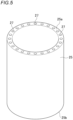
- FIG. 4 is a slant view showing a shape example of elastic members applicable to an assembled battery according to an embodiment of the present invention.
- Elastic members having the shapes shown below can all be used in place of the elastic members 5 of the assembled battery 6 shown in FIG. 2 .
- the effects, etc. of elastic members having the various shapes shown below are hence explained on the assumption that the elastic members have been applied to the assembled battery 6.
- the inner surface of the elastic member 15, which is a tubular body, has a plurality of grooves 16 formed therein which extend from one end 15a to the other end 15b of the elastic member 15.
- the terms "one end 15a” and “the other end 15b" for the elastic member 5 (tubular body) respectively mean one longitudinal-direction (top-bottom direction in FIG. 4 ) end and the other longitudinal-direction end of the elastic member 5. That is, those terms mean the open ends of the tubular body.
- An assembled battery employing elastic members 15 thus configured functions as follows like the assembled battery 6 shown in FIG. 2 .
- the flameproof material 4 inhibits the heat from being transferred and the elastic member 15 deforms in accordance with the deformation of the battery cell 2 while inhibiting the deformation of the battery cell 2. It is hence possible to inhibit the battery case 7 from being damaged and the battery cells 2 from decreasing in battery performance.
- the elastic member 15 has grooves 16 in the inner surface thereof, spaces are formed between the elastic member 15 and the flameproof material 4. Because of this, in cases when some of the heat was unable to be inhibited by the flameproof material 4 from being transferred and has been transferred to the elastic member 15 side, the gas in the spaces is heated and the high-temperature gas is discharged from the spaces to the one end 15a side and the other end 15b side of the elastic member 15. As a result, a fresh gas is introduced into the spaces and the battery cell 2 can hence be effectively cooled.
- the grooves 16 formed in the elastic member 15 are not particularly limited in the number, depth, peripheral-direction width, etc. thereof. By changing the number, depth, and peripheral-direction width of the grooves 16, the elasticity, stretchability, etc. of the elastic member 15 can be changed. It is hence possible to variously design the grooves 16 in accordance with required properties and the size of that region of the battery case 7 which is for encasing the battery cell 2 therein.
- the grooves 16 need not be always formed in a direction parallel with the longitudinal direction of the elastic member 15. However, from the standpoint of preventing the heat of the battery cell 2 from being transferred to adjoining battery cells 2, it is preferred to discharge the heated gas to the electrode surface 2a side of the battery cell 2 and to the side where the surface facing the electrode surface 2a is present. Consequently, in the case of forming grooves 16, the grooves 16 may be formed so as to extend from the one end 15a to the other end 15b of the elastic member 15.
- grooves 16 In cases when grooves 16 have been formed so as not extend in a direction parallel with the longitudinal direction of the elastic member 15 but to have a given angle with the parallel direction, it is possible to cool a wider area in the surface of the battery cell 2.
- the grooves 16 may have been formed either helically or curvedly.
- the given angle is preferably larger than 0° with respect to the parallel direction. Meanwhile, the given angle is preferably 45° or less because the heated high-temperature gas can be efficiently discharged, and is more preferably 30° or less.
- FIG. 5 is a slant view showing another shape example of elastic members applicable to the assembled battery according to an embodiment of the present invention.
- the elastic member 25, which is a tubular body is one in which the inner surface and the outer surface are smooth as in the elastic members 5 shown in FIG. 2 , but has a plurality of through holes 27 in an inner portion thereof which pierce the elastic member 25 from one end 25a to the other end 25b.
- each elastic member 25 has through holes 27 in the thickness-direction inner portion, the inside of each through hole 27 is a space. Consequently, in cases when heat generated by the battery cell 2 has reached the elastic member 25, the gas in the through holes 27 is heated and the resultant high-temperature gas is discharged from the through holes 27 to the one end 15a side and the other end 15b side of the elastic member 25. As a result, a fresh gas is introduced into the through holes 27 and the battery cell 2 can be efficiently cooled.
- the through holes 27 formed in the elastic member 25 are not particularly limited in the number, size, etc. thereof. As in the elastic member 15 shown in FIG. 4 , the through holes 27 can be variously designed in accordance with properties required of the elastic member 25 and the size of that region of the battery case 7 which is for encasing the battery cell 2 therein.
- the through holes 27 need not be always formed in a direction parallel with the longitudinal direction of the elastic member 25. In the case of forming through holes 27, the through holes 27 may be formed so as to extend from the one end 25a to the other end 25b of the elastic member 25.
- FIG. 6 is a slant view showing still another shape example of elastic members applicable to the assembled battery according to an embodiment of the present invention.
- the elastic member 35 which is a tubular body, has a shape formed by disposing a plurality of tubes side-by-side along the longitudinal direction thereof and bonding the adjoining surfaces to each other. Consequently, the elastic member 35 has a plurality of grooves 36 formed in the inner surface thereof like the elastic member 15 shown in FIG. 4 , and has a plurality of through holes 37 in a thickness-direction inner portion thereof which pierce the elastic member 35 form one end 35a to the other end 35b, like the elastic member 25 shown in FIG. 5 .
- each elastic member 35 has the grooves 36 to form spaces between the elastic member 35 and the flameproof material 4 and further has the through holes 37. Consequently, the spaces coupled with the through holes 37 enhance the effect of discharging the heated gas to the one end 35a side and the other end 35b side of the elastic member 35, making it possible to more effectively cool the battery cell 2.
- the number and size of the through holes 37 to be formed in the elastic member 35 and the depth, etc. of the grooves 36 to be formed in the elastic member 35 can be suitably designed.
- grooves 36 or through holes 37 have been formed so as to not to extend in a direction parallel with the longitudinal direction of the elastic member 35 but to have the given angle with the parallel direction, it is possible to cool a wider area in the surface of the battery cell 2.
- the grooves 36 and the through holes 37 may have been formed either helically or curvedly.
- each elastic member 5 shown in FIG. 1 may have a plurality of grooves extending from one edge surface orthogonal to the surfaces facing the flameproof materials 4 toward the other edge surface, which faces said one edge surface.
- the elastic member 5 may have a plurality of through holes piercing the elastic member 5 from one edge surface orthogonal to the surfaces facing the flameproof materials 4 to the other edge surface, which faces said one edge surface.
- the elastic member 5 may have the grooves and the through holes simultaneously.
- the flameproof sheet 10 includes the flameproof materials 4 and, for example, the elastic member 5 as described above, it is preferred to further dispose a supporting layer (not shown) between a flameproof material and the elastic member.
- the supporting layer has the effects of supporting the shape of the flameproof material and maintaining the strength of the flameproof sheet.
- the inclusion of the supporting layer in the flameproof sheet 10 is effective in preventing the pressing force due to a deformation of the battery cell from being applied to a part of the flameproof material and in inhibiting the flameproof material from breaking.
- a material for forming the supporting layer use can be made of a material having a lower modulus of elasticity and a higher hardness than the elastic member.
- a supporting layer including an organic material or an inorganic material as a main material can be used.
- the supporting layer itself is flexible and, hence, the flameproof sheet also has flexibility and can facilitate fabrication of an assembled battery.
- the supporting layer itself has heat resistance and, hence, the heat resistance of the flameproof sheet can be further improved.
- the supporting layer may have a structure obtained by laminating two or more layers differing in material.
- the supporting layer may be one in which at least one surface contains the material of the flameproof material and/or the material of the elastic member and which has been integrated with the flameproof material or the elastic member.
- the flameproof sheet has such a structure in which the supporting layer has been integrated with the flameproof material and/or the elastic member, it is possible to obtain not only the effect of improving the strength of the flameproof sheet but also the effect of inhibiting a position shift between the elastic member and the flameproof material due to sliding.
- a dusting-inhibiting effect can also be obtained.
- More preferred is a structure in which one surface of the supporting layer contains the material of the flameproof material, the other surface contains the material of the elastic member, and the flameproof material and the elastic member have been integrated with each other by the supporting layer interposed therebetween.
- This structure can further enhance the effect of inhibiting positional shifting and the effect of inhibiting dusting.
- the thickness of the supporting layer is not particularly limited.
- the supporting layer is preferably thinner than the elastic member from the standpoint of obtaining a sufficient space for disposing the elastic member and the flameproof materials.
- the thickness of the supporting layer is preferably 0.5 or more and 30% or less, more preferably 1.0% or more and 10% or less, with respect to the thickness of the elastic member. Even in the structure in which the supporting layer has been integrated with the elastic member, the relationship between the thickness of the portion that constitutes the supporting layer and the thickness of the portion that constitutes the elastic member is preferably within that range.
- the battery case 7 for encasing therein the assembled battery 6 according to this embodiment shown in FIG. 2 is not particularly limited in the material and shape thereof. Besides being a polycarbonate, the material of the battery case 7 can be PP, PET, a polyamide (PA), aluminum, stainless steel (steel use stainless; SUS), or the like. The shape of the battery case 7 can be selected at will in accordance with the device, e.g., power tool, to which the assembled battery 6 is to be applied.
- each battery cell 2 by itself has heat-insulating properties and the expansion/contraction of each battery cell 2 does not affect other regions.
- These battery cells 2 hence may not have been encased in the battery case 7.
- a plurality of battery cells 2 each covered with a flameproof material 4 and an elastic member 5 may be tied up with a band or the like to configure an assembled battery and this assembled battery as such can be mounted in a device, e.g., a power tool.
- the assembled battery according to this embodiment shown in FIG. 1 can be easily fabricated by disposing flameproof sheets 10 between battery cells 2.
- the assembled battery 6 according to this embodiment shown in FIG. 2 can be easily fabricated, as an assembled battery showing the effects described above, merely by covering each of battery cells 2 with a flameproof material 4 and putting an elastic member 5 which is, for example, a tubular body on each of the covered battery cells 2. Since a flameproof material 4 and an elastic member 5 are attached to each of the battery cells 2, a complicated design is unnecessary for the battery case 7.
- the flameproof materials 4 in cases when the flameproof materials 4 are sheet-shaped ones, the flameproof materials 4 each can be easily processed into a size suitable for covering the peripheral surface of a battery cell 2 or into a desired size regardless of the shape or size of the battery cell 2.
- the elastic members 5 in cases when the elastic members 5 are tubular, the elastic members 5 can be attached to various battery cells 2 without being affected by the shapes and sizes of the battery cells 2, since the elastic members 5 have stretchability.
- the assembled battery and battery pack according to this embodiment can be favorably used not only in power tools but in power-assisted bicycles, electric two-wheeled vehicles, electric vehicles, etc.
- the assembled battery of this embodiment is not limited to the assembled batteries shown as examples in FIG. 1 and FIG. 2 , and the flameproof sheet 10 can be disposed not only between adjoining battery cells 2 but also between a battery cell 2 and a case (e.g., a battery case 30) disposed on the outer side thereof.
- a case e.g., a battery case 30
- the flame in case where a battery cell has fired, the flame can be inhibited from spreading beyond the battery case.
- the assembled battery according to this embodiment is used in an electric vehicle (EV) or the like and may be disposed beneath the floor, under the passengers. In this case, if one of the battery cells fires, the safety of the passengers can be ensured.
- EV electric vehicle
- the safety of the passengers can be ensured.
- the flameproof sheet 10 can not only be interposed between the battery cells but also be disposed between a battery cell 2 and the battery case, there is no need of newly producing a flameproof material or the like.
- a safe assembled battery can hence be easily configured at low cost.
- the flameproof sheet 10 and the battery cell 2 may be in contact with each other or may have a gap therebetween.
- the flameproof sheet 10 when any one of the battery cells has heated up and expanded, can allow the battery cell to deform because the flameproof sheet 10 includes an elastic member 5.
Landscapes
- Chemical & Material Sciences (AREA)
- Chemical Kinetics & Catalysis (AREA)
- Electrochemistry (AREA)
- General Chemical & Material Sciences (AREA)
- Battery Mounting, Suspending (AREA)
- Secondary Cells (AREA)
Abstract
Description
- The present invention relates to a flameproof sheet for use in assembled batteries to be employed in, for example, power tools and vehicles, and to an assembled battery and a battery pack which are to be mounted in power tools, vehicles, etc. and used as power sources for electric motors, etc.
- Power tools generally include ones which are used in the state of being connected to the so-called commercial power source and ones which have an assembled battery mounted therein that serves as a power source for an electric motor for driving. The power tools having an assembled battery mounted therein are frequently used from the point of view of the excellent handleability, etc.
- An assembled battery is a battery in which a plurality of battery cells is connected serially or in parallel. For example, battery cells are enclosed in a battery case made of, for example, a polycarbonate and united therewith, and the assembled battery is housed inside a power tool.
- Mainly used as such battery cells to be mounted in power tools are lithium-ion secondary batteries, which can have higher capacities and higher outputs than lead acid batteries and nickel-hydrogen batteries. However, in case where thermal runaway has occurred in one battery cell because of internal short-circuiting, overcharge, or the like of the battery (that is, in case of " abnormality"), it is possible that heat transfer to adjoining another battery cell might occur to cause thermal runaway to the adjoining another battery cell.
- In recent years, electric vehicles driven by electric motors, hybrid vehicles, and the like are being developed enthusiastically from the standpoint of environmental protection. The electric vehicles, hybrid vehicles, and the like have assembled batteries mounted therein each including a plurality of battery cells connected serially or in parallel and serving as a power source for an electric motor for driving. Also, as such battery cells for use in vehicles, lithium-ion secondary batteries capable of having a high capacity and a high output are mainly employed. There is a possibility that these battery cells might undergo thermal runaway like the battery cells housed inside the power tools as described above.
- As a measure against the occurrence of thermal runaway described above, Patent Document 1, for example, proposes an assembled battery in which in case where abnormal heat generation has occurred, for example, because an overcurrent has flowed into a battery cell, the burning can be prevented or inhibited from spreading to adjoining battery cells. The assembled battery described in Patent Document 1 is configured of a plurality of battery cells and a block for holding the battery cells, the block being made of a metallic material and composed of a plurality of small blocks. The dimensions of the gap between the block and each battery cell are regulated.
- Patent Document 1 states that in the assembled battery described therein, which has such configuration, heat can be rapidly diffused because the block holding the battery cells is made of a metallic material.
-
Patent Document 2 discloses a battery pack intended to attain an improvement in the heat dissipation properties of secondary batteries and mitigation of performance deterioration. The battery pack described in -
Patent Document 2 is one which includes a plurality of secondary batteries enclosed in a case and in which a plate-shaped rubber sheet having a heat transfer coefficient not lower than a given value and being changed in shape by pressure has been disposed between the plurality of batteries and the case. -
Patent Document 2 states that since the heat transfer coefficient of the rubber sheet is relatively high, the heat of the secondary batteries can be satisfactorily discharged via the case. Furthermore, this battery pack can be prevented from being damaged when dropped, since the rubber sheet has elasticity. -
- Patent Document 1:
JP2014-96271A - Patent Document 2:
JP2004-146161A - Incidentally, in case where thermal runaway occurs in a battery cell, a gas is generated within this battery to elevate the internal pressure and thus cause a deformation of the battery cell. This deformation, when large, may cause breakage of the case.
- Such a battery-cell deformation occurs slightly also in cases when battery cells which have been fabricated into an assembled battery are subjected to charge/discharge cycling (that is, "during ordinary use"). In cases when the internal pressure of battery cells repeatedly increases and decreases during charge/discharge, the battery cells repeatedly undergo pressing by the case and relaxation thereof and this is causative of a decrease in battery performance.
- Although the assembled battery according to Patent Document 1 is capable of rapidly diffusing heat since the block holding the battery cells is made of a metallic material, this assembled battery has no provision against the breakage of the battery case and the decrease in battery performance due to a battery-cell deformation.
- In addition, the assembled battery described in Patent Document 1 necessitates a plurality of blocks and the blocks need to be designed in accordance with the electronic appliance, power tool, or the like in which the assembled battery is to be mounted, since the gaps between the blocks and the battery cells are varied. There is hence a problem in that the design of the blocks and fabrication of the assembled battery are complicated.
- Furthermore, in the battery pack described in
Patent Document 2, it is not considered that in the case where the thermal runaway occurs in a battery cell, the thermal runaway in an adjoining battery cell is to be inhibited. - An object of the present invention, which has been achieved in view of those problems, is to provide: a flameproof sheet which can inhibit heat transfer between battery cells in case of abnormality and inhibit battery-case breakage and a decrease in battery performance due to battery-cell deformations; and an assembled battery and a battery pack which are easy to design and fabricate and in which heat transfer between the battery cells can be inhibited and battery-case breakage and a decrease in battery performance can be inhibited.
- The object of the present invention is accomplished with the following configuration [1] regarding a flameproof sheet.
-
- [1] A flameproof sheet for use in an assembled battery in which a plurality of battery cells is connected serially or in parallel, the battery cells each having an electrode surface having an electrode and a peripheral surface orthogonal to the electrode surface and being disposed such that the peripheral surfaces face each other,
the flameproof sheet including a pair of flameproof materials and an elastic member disposed between the pair of flameproof materials. - Preferred embodiments of the present invention according to the flameproof sheet relate to the following [2] to [10],
- [2] The flameproof sheet according to [1] wherein the elastic member has a plurality of grooves extending from one edge surface thereof orthogonal to surfaces thereof facing the flameproof materials to the other edge surface.
- [3] The flameproof sheet according to [1] or [2] wherein the elastic member has a plurality of through holes piercing the elastic member from one edge surface thereof orthogonal to surfaces thereof facing the flameproof materials to the other edge surface.
- [4] The flameproof sheet according to any one of [1] to [3] wherein the elastic member is made of a rubber or an elastomer.
- [5] The flameproof sheet according to any one of [1] to [4] wherein the flameproof materials contain at least one kind of inorganic particles, organic fibers, or inorganic fibers.
- [6] The flameproof sheet according to [5] characterized in that the inorganic particles are particles of at least one inorganic material selected from among oxide particles, carbide particles, nitride particles, and inorganic hydrate particles.
- [7] The flameproof sheet according to any one of [1] to [6] characterized in that the flameproof materials include first inorganic fibers and second inorganic fibers, the first inorganic fibers and the second inorganic fibers differing from each other in at least one property selected from among average fiber diameter, shape, and glass transition point.
- [8] The flameproof sheet according to [7] characterized in that
- the first inorganic fibers have a larger average fiber diameter than the second inorganic fibers, and
- the first inorganic fibers are linear or acicular and the second inorganic fibers are dendritic or curly.
- [9] The flameproof sheet according to [7] characterized in that
- the first inorganic fibers are amorphous fibers,
- the second inorganic fibers are fibers of at least one kind selected from between amorphous fibers, having a higher glass transition point than the first inorganic fibers, and crystalline fibers, and
- the first inorganic fibers have a larger average fiber diameter than the second inorganic fibers.
- [10] The flameproof sheet according to [7] wherein the flameproof materials contain inorganic particles, the inorganic particles comprising particles of at least one kind selected from among nanoparticles, hollow particles, and porous particles,
- the first inorganic fibers are amorphous fibers, and
- the second inorganic fibers are inorganic fibers of at least one kind selected from between amorphous fibers, having a higher glass transition point than the first inorganic fibers, and crystalline fibers.
- The object of the present invention is accomplished also with the following configurations [11] and [12] regarding an assembled battery.
- [11] An assembled battery including a plurality of battery cells and the flameproof sheet according to any one of [1] to [10], wherein the plurality of battery cells are connected directly or in parallel.
- [12] An assembled battery in which a plurality of battery cells that each have an electrode surface having an electrode and a peripheral surface orthogonal to the electrode surface and that are disposed such that the peripheral surfaces face each other are connected serially or in parallel,
- the assembled battery including
- the battery cells,
- a flameproof material covering at least a part of the peripheral surfaces of the battery cells, and
- an elastic member covering at least a part of a region of the peripheral surfaces of the battery cells which is covered with the flameproof material.
- Preferred embodiments of the present invention according to the assembled batteries relate to the following [13] to [16].
- [13] The assembled battery according to [12] wherein the elastic member covers the flameproof-material-covered region along a peripheral direction of the battery cells to press the battery cells.
- [14] The assembled battery according to [13] wherein the elastic member is a tubular body which is open at both ends.
- [15] The assembled battery according to [14] wherein the elastic member has a plurality of grooves extending in an inner surface of the tubular body from one end to the other end of the tubular body.
- [16] The assembled battery according to [14] or [15] wherein the elastic member has a plurality of through holes piercing the tubular body from one end to the other end thereof.
- The object of the present invention is accomplished also with the following configuration [17] regarding a battery pack.
- [17] A battery pack in which the assembled battery according to any one of [11] to [16] is encased in a battery case.
- Since the flameproof sheet of the present invention includes a pair of flameproof materials and an elastic member disposed between the pair of flameproof materials, not only it is possible to inhibit the transfer of heat between battery cells in case of abnormality but also the elastic member can flexibly deform in accordance with deformations of the battery cells to inhibit battery-case breakage and a decrease in battery performance.
- Since the assembled battery of the present invention includes a flameproof material covering at least a part of the peripheral surfaces of the battery cells, it is possible to inhibit the transfer of heat between battery cells in case of abnormality. Since this assembled battery includes an elastic member covering at least a part of the peripheral surfaces of the flameproof material, the elastic member can flexibly deform in accordance with deformations of the battery cells to inhibit battery-case breakage and a decrease in battery performance. Furthermore, in cases when the elastic member is a tubular body, this elastic member has stretchability and can hence be easily attached to each battery cell, without the need of changing the designs of the elastic member and battery case in accordance with the kind of battery cells.
- Since the battery pack of the present invention includes the assembled battery encased, not only the transfer of heat between the battery cells can be inhibited and the propagation of thermal runaway can be prevented, but also this battery pack can be easily fabricated.
-
-
FIG. 1 is a cross-sectional view schematically illustrating an assembled battery employing a flameproof sheet according to an embodiment of the present invention. -
FIG. 2 is a cross-sectional view schematically illustrating a battery pack according to an embodiment of the present invention. -
FIG. 3 is a cross-sectional view schematically illustrating a flameproof material containing two kinds of inorganic particles. -
FIG. 4 is a slant view showing a shape example of elastic members applicable to an assembled battery according to an embodiment of the present invention. -
FIG. 5 is a slant view showing another shape example of elastic members applicable to the assembled battery according to an embodiment of the present invention. -
FIG. 6 is a slant view showing still another shape example of elastic members applicable to the assembled battery according to an embodiment of the present invention. - The present inventor diligently made investigations in order to provide an assembled battery in which heat transfer between the battery cells is inhibited in case of abnormality and any deformation of battery cells does not affect the battery case or the battery performance.
- As a result, the inventor has discovered that the problems described above can be eliminated by covering at least a part of the peripheral surface of each battery cell with a flameproof material and covering at least a part of the flameproof-material-covered region with an elastic member.
- Embodiments of the present invention are described in detail below while referring to the drawings. The present invention is not limited to the following embodiments, and can be modified at will so long as the modifications do not depart from the spirit of the invention.
-
FIG. 1 is a cross-sectional view schematically illustrating an assembled battery employing a flameproof sheet according to an embodiment of the present invention. - Each
battery cell 2 has anelectrode surface 2a having anelectrode 3 and aperipheral surface 2b that is a surface orthogonal to theelectrode surface 2a. Thebattery cells 2 have been disposed so that theperipheral surfaces 2b thereof face each other, and are connected serially or in parallel, with theelectrodes 3 and a connector (not shown), etc. interposed therebetween. -
Flameproof sheets 10 have been disposed between the plurality ofbattery cells 2. Theflameproof sheets 10 each include a pair offlameproof materials 4 and anelastic member 5 disposed between the pair offlameproof materials 4. That is, asFIG. 1 shows, eachflameproof material 4 covers at least a part of the peripheral surface of abattery cell 2, and theelastic member 5 covers at least a part of the region covered with theflameproof material 4. The assembledbattery 100 has been configured by encasing the plurality ofbattery cells 2 and theflameproof materials 4 in abattery case 30. - The
flameproof sheet 10, which has such configuration, disposed betweenbattery cells 2 functions as follows. When thermal runaway has occurred in one of the battery cells in case of abnormality, theflameproof materials 4 inhibit the transfer of the heat to the adjoining battery cell. Hence, the other battery cell, which adjoins said one battery cell, can be inhibited from receiving the heat and the thermal runaway can be prevented from propagating. - The
flameproof sheet 10 includes anelastic member 5 disposed between the pair offlameproof materials 4, and thiselastic member 5 has both the effect of inhibiting thebattery cells 2 from deforming and the effect of absorbing deformations of thebattery cells 2. That is, when abattery cell 2 deforms in case of abnormality, theelastic member 5 flexibly deforms in accordance with the deformation of thebattery cell 2 while inhibiting the deformation of thebattery cell 2. It is hence possible to inhibit a pressure from being unnecessarily applied to thebattery cells 2. - In this embodiment, the
flameproof materials 4 have been disposed so as to be in contact with a part of the peripheral surfaces of thebattery cells 2, and theelastic members 5 are not in contact with thebattery cells 2. This configuration is advantageous in that when abattery cell 2 has heated up to a high temperature in case of abnormality, the heat is less apt to reach theelastic member 5 and, hence, theelastic member 5 can be prevented from melting. Also, in cases when thebattery cells 2 have changed in temperature during ordinary use, the disposition of aflameproof material 4 between eachbattery cell 2 and theelastic member 5 makes theelastic member 5 undergo a reduced temperature change and can prevent theelastic member 5 from deteriorating. - It is, however, possible, depending on the material of the
elastic member 5, to employ a flameproof sheet configured so that theelastic member 5 is in contact with theperipheral surface 2b of abattery cell 2, that is, aflameproof material 4 has been disposed between a pair ofelastic members 5. Specifically,elastic members 5 are disposed in the positions of theflameproof materials 4 shown inFIG. 1 and aflameproof material 4 is disposed in the position of theelastic member 5 inFIG. 1 . Since there are cases where theflameproof materials 4 contain inorganic particles having an extremely small particle diameter, such as nanoparticles, as will be described later, the configuration including aflameproof material 4 disposed between a pair ofelastic members 5 can prevent the inorganic particles from shedding from theflameproof material 4. It is preferred to suitably select the positional relationship between theelastic member 5 and theflameproof material 4 in such a manner while taking account of the material of theflameproof material 4, the heat resistance, elasticity, and durability of theelastic member 5, etc. - Incidentally, the
battery cells 2 undergo slight deformations during charge/discharge cycling, i.e., during ordinary use. That is, in cases when the gap between the plurality ofbattery cells 2 is small, thebattery cells 2, when having expanded, each are pressed by an opposedbattery cell 2 and thebattery cells 2, when having contracted, are released from the pressure. Such repetitions of the pressing of thebattery cells 2 and the relaxation are causative of a decrease in battery performance. - In this embodiment, since the
elastic member 5 deforms flexibly in accordance with even slight deformations of thebattery cells 2 in charge/discharge cycling during ordinary use, it is possible to inhibit thebattery cells 2 from decreasing in battery performance. - In this embodiment, the
battery cells 2 may be prismatic or round. - Although each
flameproof sheet 10 has been disposed between a plurality ofbattery cells 2 in this embodiment, theflameproof sheet 10 may cover theperipheral surface 2b of abattery cell 2 along the peripheral direction. For example, use can be made of aflameproof sheet 10 configured so that aflameproof material 4 is wound around theperipheral surface 2b of abattery cell 2 along the peripheral direction and anelastic member 5 only is disposed between adjoining battery cells. Use may also be made of aflameproof sheet 10 configured so that aflameproof material 4 is wound around theperipheral surface 2b of abattery cell 2 along the peripheral direction and anelastic member 5 is disposed so as to be wound around theperipheral surface 2b of theflameproof material 4. - Examples of an assembled battery in which a
flameproof material 4 and anelastic member 5 have been disposed so as to cover theperipheral surface 2b of abattery cell 2 along the peripheral direction and of a battery pack including this assembled battery are explained in detail below. -
FIG. 2 is a cross-sectional view schematically illustrating the battery pack according to an embodiment of the present invention. - The battery pack 1 is one obtained by encasing an assembled
battery 6, which is described in detail below, in abattery case 7 made of, for example, a resin. - Each
battery cell 2 has anelectrode surface 2a having anelectrode 3 and aperipheral surface 2b that is a surface orthogonal to theelectrode surface 2a. Thebattery cells 2 have been disposed so that theperipheral surfaces 2b thereof face each other, and are connected serially or in parallel, with theelectrodes 3 and a connector (not shown), etc. interposed therebetween. - The
peripheral surface 2b of eachbattery cell 2 is covered with aflameproof material 4 and the peripheral surface of theflameproof material 4 is covered with anelastic member 5, thereby configuring the assembledbattery 6. Theelastic member 5 is a tubular body which is open at both ends, and covers the peripheral surfaces of thebattery cell 2 andflameproof material 4 along the peripheral direction. In this embodiment, the expression "both ends of the elastic member 5 (tubular body)" means one longitudinal-direction (top-bottom direction inFIG. 2 ) end of theelastic member 5 and the other end thereof, namely, the open ends of the tubular body. - In the assembled
battery 6 having such configuration, theperipheral surface 2b of eachbattery cell 2 is covered with theflameproof material 4. Because of this, when thermal runaway has occurred in one of the battery cells in case of abnormality, theflameproof material 4 inhibits the transfer of the heat to the periphery. Hence, the other battery cell, which adjoins said one battery cell, can be inhibited from receiving the heat and the thermal runaway can be prevented from propagating. - The
elastic member 5, which covers the peripheral surfaces of thebattery cell 2 andflameproof material 4 to press thebattery cell 2, has both the effect of inhibiting thebattery cell 2 from deforming and the effect of absorbing any deformation of thebattery cell 2. That is, when thebattery cell 2 deforms in case of abnormality, theelastic member 5 deforms flexibly in accordance with the deformation of thebattery cell 2 while inhibiting the deformation of thebattery cell 2. It is hence possible to inhibit thebattery case 7 from breaking. - Furthermore, even when the
battery cell 2 has heated up to a high temperature in case of abnormality and exploded due to an increase in internal pressure, the covering of thebattery cell 2 with theelastic member 5 makes it possible to avoid a trouble, for example, that fragments of thebattery cell 2, an organic electrolytic liquid present in thebattery cell 2, etc. reachother battery cells 2 to exert an adverse influence. - Incidentally, each
battery cell 2 undergoes slight deformations during charge/discharge cycling, i.e., during ordinary use. That is, in cases when the gap between thebattery cell 2 and thebattery case 7 is small, thebattery cell 2, when having expanded, is pressed by thebattery case 7 and thebattery cell 2, when having contracted, is released from the pressure by thebattery case 7. Such repetitions of the pressing of thebattery cell 2 and the relaxation are causative of a decrease in battery performance. - In this embodiment, since the
elastic member 5 deforms flexibly in accordance with even slight deformations of thebattery cell 2 in charge/discharge cycling during ordinary use, it is possible to inhibit thebattery cell 2 from decreasing in battery performance. - In this embodiment, the
battery cells 2 may be prismatic or round. - The assembled battery has preferably been configured so that, as
FIG. 2 shows, eachflameproof material 4 covers all of the peripheral surface of thebattery cell 2 to press thebattery cell 2. However, a configuration in which a part of the peripheral surface remains uncovered, as shown inFIG. 1 can be favorably used according to need so long as such configuration can inhibit the propagation of thermal runaway such as that described above. - The
elastic member 5 need not cover all of the peripheral surface of thebattery cell 2 covered with theflameproof material 4, and may be one which can be expected to produce the above-described effects of theelastic member 5. For example, theelastic member 5 may be one which covers a part of theperipheral surface 2b of thebattery cell 2 as shown inFIG. 1 . Even with such a configuration, the effects of theelastic member 5 can be sufficiently obtained as stated above. - Next, the
flameproof materials 4 andelastic members 5 which are components of the assembled battery according to this embodiment are described in detail. - The
flameproof materials 4 to be used in the assembledbattery 6 according to this embodiment preferably contain organic fibers and/or inorganic fibers, and more preferably further contain inorganic particles according to need. In this embodiment, use can be made of these materials which have been processed into, for example, a sheet shape. Since it is important that materials for constituting theflameproof materials 4 should have heat-insulating properties, these materials are selected from among materials having high heat-insulating performance. - Examples indexes to heat-insulating performance include heat transfer coefficient. In this embodiment, the
flameproof materials 4 have a heat transfer coefficient of preferably less than 1 (W/m·K), more preferably less than 0.5 (W/m·K), still more preferably less than 0.2 (W/m·K). The heat transfer coefficient of theflameproof materials 4 is yet still more preferably less than 0.1 (W/m·K), even still more preferably less than 0.05 (W/m·K), especially preferably less than 0.02 (W/m·K). - The heat transfer coefficient of a
flameproof material 4 can be measured in accordance with "Test Method for Heat Transfer Coefficients of Refractories" described in JIS R 2251. - The inorganic particles are preferably ones made of one or more compounds having heat resistance. Either inorganic particles made of a single material may be used, or inorganic particles of two or more kinds differing in material may be used in combination. In cases when inorganic particles of two or more kinds differing in heat-transfer-inhibiting effect are used in combination, heat-generating objects can be cooled in multiple stages and a heat sink action can be exhibited over a wider temperature range, making it possible to improve the heat-insulating performance. In the case where inorganic particles of two or more kinds are contained, preferred materials, shapes, and particle diameters of each kind of inorganic particles are as follows.
-
FIG. 3 is a cross-sectional view schematically illustrating aflameproof material 4 containing two kinds of inorganic particles. Theflameproof material 4 shown inFIG. 3 contains, as examples, firstinorganic particles 41 and secondinorganic particles 12 and further contains two kinds of inorganic fibers (firstinorganic fibers 31 and second inorganic fibers 32),organic fibers 43, and abinder 9, which will be described later. - As the first
inorganic particles 41 and the secondinorganic particles 12, it is preferred to use particles of at least one inorganic material selected from among oxide particles, carbide particles, nitride particles, and inorganic hydrate particles, from the standpoint of heat-transfer-inhibiting effect. More preferred is to use oxide particles. It is also possible to use silica nanoparticles, metal oxide particles, microporous particles, inorganic balloons such as hollow silica particles, particles made of a heat-expandable inorganic material, particles made of a hydrous porous material, or the like. The inorganic particles are explained in greater detail below; in the following explanation, inorganic particles having smaller diameters are referred to as firstinorganic particles 41 and inorganic particles having larger particle diameters are referred to as secondinorganic particles 12. - Oxide particles have high refractive indexes and are highly effective in irregularly reflecting light. Use of oxide particles as the inorganic particles hence makes it possible to inhibit radiational heat transfer in a high-temperature range as in, especially, abnormal heat generation. Examples of the oxide particles include silica (SiO2), titania (TiO2), mullite (Al6O13Si2), zirconia (ZrO2), magnesia (MgO), zircon (ZrSiO4), barium titanate (BaTiO3), zinc oxide (ZnO), and alumina (Al2O3). However, the oxide particles are not limited to those examples. That is, only one kind selected from among those particulate oxide materials usable as the inorganic particles may be used, or two or more kinds of oxide particles may be used. In particular, silica is an ingredient having high heat-insulating properties, and titania is an ingredient having a high refractive index as compared with other metal oxides and is highly effective in irregularly reflecting light to block radiation heat in a high-temperature range of 500°C and above. It is hence most preferred to use silica and titania as the oxide particles.
- The particle diameters of the oxide particles may affect the effect of reflecting radiation heat. Hence, by limiting the average primary-particle diameter to a given range, even higher heat-insulating properties can be obtained.
- Specifically, in cases when the oxide particles have an average primary-particle diameter of 0.001 µm or larger, these oxide particles are sufficiently larger than the wavelengths of light contributing to heating and irregularly reflect the light efficiently. Consequently, radiational heat transfer within the
flameproof materials 4 in the high-temperature range of 500°C and above is inhibited and the heat-insulating properties can be further improved. - Meanwhile, in cases when the oxide particles have an average primary-particle diameter of 50 µm or less, the oxide particles, even when compressed, do not increase in the area or number of interparticulate contact points and are less apt to form paths for conductive heat transfer It is hence possible to reduce influences on the heat-insulating properties in an ordinary-temperature range, where conductive heat transfer is dominant.
- In the present invention, an average primary-particle diameter can be determined by examining the particles with a microscope and averaging the particle diameters of arbitrarily selected 10 particles while comparing the particle diameters with a standard scale.
- In the present invention, the term "nanoparticles" means particles which are spherical or approximately spherical and have an average primary-particle diameter less than 1 µm, on the order of nanometer. Nanoparticles have a low density and hence inhibit conductive heat transfer In cases when nanoparticles are used as the inorganic particles, voids are more finely dispersed and, hence, excellent heat-insulating properties which inhibit convectional heat transfer can be obtained. Because of this, use of nanoparticles is preferred in that when the battery is used in an ordinary temperature range, heat transfer between adjacent nanoparticles can be inhibited.
- Furthermore, in cases when nanoparticles, which have a small average primary-particle diameter, are used as the oxide particles, the
flameproof material 4 can be inhibited from undergoing enhanced conductive heat transfer even when the battery cell has expanded due to thermal runaway and the expansion has compressed theflameproof material 4 and heightened the density of an inner portion of the flameproof material. This seems to be because the nanoparticles are apt to show electrostatic repulsion to form fine voids between the particles and have a low bulk density and are hence packed so as to have cushioning properties. - In the case of using nanoparticles as the inorganic particles in the present invention, the material thereof is not particularly limited so long as the nanoparticles meet the definition of nanoparticles. For example, silica nanoparticles are a material having high heat-insulating properties and have a feature of having small interparticulate contact points. Consequently, the quantity of heat conducted by silica nanoparticles is smaller than in the case of using silica particles having a large particle diameter. In addition, since generally available silica nanoparticles have bulk densities of about 0.1 (g/cm3), the silica nanoparticles in a flameproof material do not increase considerably in the size (area) or number of contact points therebetween and can retain the heat-insulating properties, even when, for example, the battery cell disposed so as to adjoin the flameproof material has thermally expanded to impose high compressive stress on the flameproof material. It is therefore preferred to use silica nanoparticles as the nanoparticles. Usable as the silica nanoparticles are wet-process silica, dry-process silica, aerogel, and the like.
- By limiting the average primary-particle diameter of the nanoparticles to a given range, even higher heat-insulating properties can be obtained.
- Specifically, by regulating the nanoparticles so as to have an average primary -particle diameter of 1-100 nm, convectional heat transfer and conductive heat transfer within the
flameproof materials 4 especially in a temperature range below 500°C can be inhibited and the heat-insulating properties can be further improved. Even in cases when compressive stress has been imposed, the voids remaining among the nanoparticles and contact points between many particles inhibit conductive heat transfer, enabling theflameproof materials 4 to retain the heat-insulating properties. - The average primary-particle diameter of the nanoparticles is more preferably 2 nm or larger, still more preferably 3 nm or larger Meanwhile, the average primary -particle diameter of the nanoparticles is more preferably 50 nm or less, still more preferably 10 nm or less.
- Inorganic hydrate particles, when heated to a temperature not lower than the pyrolysis initiation temperature upon reception of heat from a heat-generating object, decompose thermally to release the crystal water included in itself and lower the temperatures of the heat-generating object and periphery thereof. That is, inorganic hydrate particles perform the so-called "heat sink action". After the release of the crystal water, the particles are porous and perform heat-insulating action due to the innumerable voids.
- Specific examples of the inorganic hydrate include aluminum hydroxide (Al(OH)3), magnesium hydroxide (Mg(OH)2), calcium hydroxide (Ca(OH)2), zinc hydroxide (Zn(OH)2), iron hydroxide (Fe(OH)2), manganese hydroxide (Mn(OH)2), zirconium hydroxide (Zr(OH)2), and gallium hydroxide (Ga(OH)3).
- For example, aluminum hydroxide has about 35% crystal water, and decomposes thermally to release the crystal water as shown by the following formula and exhibits a heat sink action. After having released the crystal water, the aluminum compound is porous alumina (Al2O3) and functions as a flameproof material.
2Al(OH)3 → Al2O3 + 3H2O
- As will be described later, a
flameproof material 4 and anelastic member 5 according to this embodiment are favorably disposed, for example, between battery cells. However, since a battery cell which is undergoing thermal runaway heats up rapidly to a temperature exceeding 200°C and continues to heat up to around 700°C, the inorganic particles are preferably made of an inorganic hydrate having a pyrolysis initiation temperature of 200°C or higher. - The inorganic hydrates mentioned above have the following pyrolysis initiation temperatures: aluminum hydroxide, about 200°C; magnesium hydroxide, about 330°C; calcium hydroxide, about 580°C; zinc hydroxide, about 200°C; iron hydroxide, about 350°C; manganese hydroxide, about 300°C; zirconium hydroxide about 300°C; and gallium hydroxide, about 300°C. These pyrolysis initiation temperatures are substantially within the temperature range over which the battery cell in which thermal runaway is occurring heats up rapidly, and are effective in efficiently inhibiting the temperature increase. Those inorganic hydrates are hence preferred.
- In the case of using inorganic hydrate particles as the first
inorganic particles 41, if the inorganic hydrate particles have too large an average particle diameter, then first inorganic particles 41 (inorganic hydrate) lying around the center of theflameproof material 4 require time to some degree before the particles can heat up to the pyrolysis initiation temperature. There are hence cases where the firstinorganic particles 41 lying around the center of theflameproof material 4 are not completely pyrolyzed. Because of this, the inorganic hydrate particles have an average secondary-particle diameter of preferably 0.01-200 µm, more preferably 0.05-100 µm. - Preferred examples of the nitride particles include boron nitride (BN).
- Preferred examples of the carbide particles include boron carbide (BaC).
- Examples of the heat-expandable inorganic material include vermiculite, bentonite, mica, and perlite.
- Specific examples of the hydrous porous material include zeolite, kaolinite, montmorillonite, acid clay, diatomaceous earth, wet-process silica, dry-process silica, aerogel, mica, and vermiculite.
- The
flameproof materials 4 to be used in the present invention may contain inorganic balloons as the inorganic particles. - The inclusion of inorganic balloons can inhibit convectional heat transfer and conductive heat transfer within the
flameproof materials 4 in a temperature range below 500°C and can further improve the heat-insulating properties of theflameproof materials 4. - As the inorganic balloons, use can be made of at least one kind selected from among shirasu balloons, silica balloons, fly ash balloons, pearlite balloons, and glass balloons.
- The content of the inorganic balloons is preferably 60 mass% or less with respect to the whole mass of the flameproof material.
- The inorganic balloons have an average particle diameter of preferably 1-100 µm.
- In the case where the
flameproof materials 4 contain two kinds of inorganic particles, the secondinorganic particles 12 are not particularly limited so long as the secondinorganic particles 12 differ from the firstinorganic particles 41 in material, particle diameter, etc. As the secondinorganic particles 12, use can be made of oxide particles, carbide particles, nitride particles, inorganic hydrate particles, silica nanoparticles, metal oxide particles, microporous particles, inorganic balloons such as hollow silica particles, particles made of a heat-expandable inorganic material, particles made of a hydrous porous material, or the like. Details of these particulate materials are as described hereinabove. - Nanoparticles are extremely low in conductive heat transfer and enable the flameproof materials to retain excellent heat-insulating properties even under compressive stress. Metal oxide particles such as titania are highly effective in blocking radiation heat. In cases when inorganic particles having a large diameter and inorganic particles having a small diameter are used, the small-diameter inorganic particles come into interstices among the large-diameter inorganic particles, resulting in a denser structure. The heat-transfer-inhibiting effect can hence be improved. Consequently, in the case where nanoparticles are used as the first inorganic particles 51, it is preferable that particles made of a metal oxide and having a larger diameter than the first
inorganic particles 41 are further incorporated as the secondinorganic particles 12 into theflameproof materials 4. - Examples of the metal oxide include silicon oxide, titanium oxide, aluminum oxide, barium titanate, zinc oxide, zircon, and zirconium oxide. In particular, titania is an ingredient having a high refractive index as compared with other metal oxides and is highly effective in irregularly reflecting light to block radiation heat in a high-temperature range of 500°C and above. It is hence most preferred to use titania.
- In the case where second
inorganic particles 12 made of a metal oxide are contained in theflameproof materials 4, the secondinorganic particles 12, when having an average primary-particle diameter of 1-50 µm, can efficiently inhibit radiational heat transfer in the high-temperature range of 500°C and above. The average primary-particle diameter of the secondinorganic particles 12 is more preferably 5-30 µm, most preferably 10 µm or less. - In the case where the first
inorganic particles 41 are silica nanoparticles and the secondinorganic particles 12 are a metal oxide, when the content of the firstinorganic particles 41 is 60 mass% or more and 95 mass% or less with respect to the total mass of the firstinorganic particles 41 and secondinorganic particles 12, then it is possible to optimize both the amount of metal oxide particles necessary for inhibiting radiational heat transfer and the amount of silica nanoparticles necessary for inhibiting conductive/convectional heat transfer and for cushioning properties. - It is thought that, as a result, high heat-insulating properties are obtained with a satisfactory balance over a wide temperature range from temperatures during ordinary use of the battery to high temperatures of 500°C and above, even when compressive force is imposed externally.
- Examples of the inorganic fibers include ceramic fibers such as silica fibers, alumina fibers, aluminosilicate fibers, zirconia fibers, carbon fibers, soluble fibers, refractory ceramic fibers, aerogel composite materials, magnesium silicate fibers, alkaline-earth silicate fibers, potassium titanate fibers, and potassium titanate whisker fibers, glass-based fibers such as glass fibers and glass wool, and mineral fibers such as rock wool, basalt fibers, and wollastonite.
- These inorganic fibers are preferred from the standpoints of heat resistance, strength, availability, etc. Especially preferred of those inorganic fibers from the standpoint of handleability are silica-alumina fibers, alumina fibers, silica fibers, rock wool, alkaline-earth silicate fibers, and glass fibers.
- The cross-sectional shape of the inorganic fibers is not particularly limited, and examples thereof include a circular cross-section, a flat cross-section, a hollow cross-section, a polygonal cross-section, and a core cross-section. Of these, fibers having an unusual cross-section such as a hollow, flat, or polygonal cross-section are suitable for use because such fibers slightly improve the heat-insulating properties.
- Unless the inorganic fibers have the special properties which will be described later, a preferred lower limit of the average fiber length of the inorganic fibers is 0.1 mm, and a more preferred lower limit thereof is 0.5 mm. Meanwhile, a preferred upper limit of the average fiber length of the inorganic fibers is 50 mm, and a more preferred upper limit thereof is 10 mm. In case where the average fiber length of the inorganic fibers is less than 0.1 mm, the inorganic fibers are less apt to be intertwined with each other and this may reduce the mechanical strength of the
flameproof material 4. Meanwhile, in case where the average fiber length thereof exceeds 50 mm, the inorganic fibers, although having a reinforcing effect, cannot be tightly intertwined with each other, or the individual inorganic fibers separately become round and this is prone to form continuous voids and may hence result in a decrease in heat-insulating property. - Unless the inorganic fibers have the special properties which will be described later, a preferred lower limit of the average fiber diameter of the inorganic fibers is 1 µm, a more preferred lower limit thereof is 2 µm, and a still more preferred lower limit thereof is 3 µm. Meanwhile, a preferred upper limit of the average fiber diameter of the inorganic fibers is 15 µm, and a more preferred upper limit thereof is 10 µm. In case where the average fiber diameter of the inorganic fibers is less than 1 µm, the inorganic fibers themselves are likely to have reduced mechanical strength. From the standpoint of influences on human health, the average fiber diameter of the inorganic fibers is preferably 3 µm or larger. Meanwhile, in case where the average fiber diameter of the inorganic fibers is larger than 15 µm, there is a possibility that heat transfer by the inorganic fibers as a solid medium might be enhanced to result in a decrease in heat-insulating property and that the flameproof material might be deteriorated in shapability and strength.
- Inorganic fibers of one kind may be used alone, or two or more kinds of inorganic fibers may be used in combination. The
flameproof material 4 preferably includes firstinorganic fibers 31 and secondinorganic fibers 32 which differ from the firstinorganic fibers 31 in at least one property selected from among, for example, average fiber diameter, shape, and glass transition point, as shown inFIG. 3 . The inclusion of inorganic fibers of two kinds differing in property can improve the mechanical strength of theflameproof material 4 and the retention of inorganic particles. - In the case where the
flameproof material 4 includes two kinds of inorganic fibers, it is preferable that the firstinorganic fibers 31 have a larger average fiber diameter than the secondinorganic fibers 32 and that the firstinorganic fibers 31 are linear or acicular and the secondinorganic fibers 32 are dendritic or curly. Firstinorganic fibers 31 which have a large average fiber diameter (thick) have the effect of improving the mechanical strength and shape retentivity of theflameproof material 4. That effect can be obtained by selecting two kinds of inorganic fibers so that one of the two kinds, for example, the firstinorganic fibers 31, is thicker than the secondinorganic fibers 32. There are cases where theflameproof material 4 receives external impacts, and the inclusion of the firstinorganic fibers 31 in theflameproof material 4 enhances the impact resistance. Examples of the external impacts include pressing force due to the expansion of the battery cell and wind pressure due to the firing of the battery cell. - From the standpoint of improving the mechanical strength and shape retentivity of the
flameproof material 4, the firstinorganic fibers 31 especially preferably are linear or acicular. The term "liner or acicular fiber" means a fiber having a degree of crimpiness, which will be described later, of, for example, less than 10%, preferably 5% or less. - More specifically, from the standpoint of improving the mechanical strength and shape retentivity of the
flameproof material 4, the average fiber diameter of the firstinorganic fibers 31 is preferably 1 µm or larger, more preferably 3 µm or larger In case where the firstinorganic fibers 31 are too thick, this may result in a decrease in shapability or processability into theflameproof material 4. Hence, the average fiber diameter of the firstinorganic fibers 31 is preferably 20 µm or less, more preferably 15 µm or less. - Incidentally, too large lengths of the first
inorganic fibers 31 may result in a decrease in shapability or processability. The fiber length thereof is hence preferably 100 mm or less. Furthermore, since too small lengths of the firstinorganic fibers 31 result in decreases in shape retentivity and mechanical strength, the fiber length thereof is preferably 0.1 mm or larger. - Meanwhile, second
inorganic fibers 32 which have a small average fiber diameter (thin) have the effects of improving the retention of other inorganic fibers, inorganic particles, etc. and enhancing the flexibility of theflameproof material 4. It is hence preferable that the secondinorganic fibers 32 are thinner than the firstinorganic fibers 31. - More specifically, from the standpoint of improving the retention of other inorganic fibers, inorganic particles, etc., the second
inorganic fibers 32 preferably are easy to deform and have flexibility. Hence, the secondinorganic fibers 32 which are thin have an average fiber diameter of preferably less than 1 µm, more preferably 0.1 µm or less. It is, however, noted that thin inorganic fibers which are too thin are prone to break and are causative of a decrease in the retention of other inorganic fibers, inorganic particles, etc. In addition, a larger proportion of such too thin inorganic fibers are present in a mere intertwined state, without retaining other inorganic fibers, inorganic particles, etc., in theflameproof material 4, resulting not only in a decrease in the ability to retain other inorganic fibers, inorganic particles, etc. but also in poor shapability and poor shape retentivity. Because of this, the average fiber diameter of the secondinorganic fibers 32 is preferably 1 nm or larger, more preferably 10 nm or larger. - In case where the second
inorganic fibers 32 are too long, this results in decreases in shapability and shape retentivity. Hence, the fiber length of the secondinorganic fibers 32 is preferably 0.1 mm or less. - The second
inorganic fibers 32 preferably are dendritic or curly. The secondinorganic fibers 32 having such a shape are intertwined with other inorganic fibers, inorganic particles, etc. in theflameproof material 4. Hence, the ability to retain other inorganic fibers, inorganic particles, etc. improves. Moreover, in cases when theflameproof material 4 and theelastic member 5 receive pressing force or wind pressure, theflameproof material 4 is inhibited from sliding and moving, by the intertwining of the firstinorganic fibers 31 with the secondinorganic fibers 32. This improves the mechanical strength especially against external pressing force and impacts. - The term "dendritic" means a two-dimensionally or three-dimensionally branched structure, and examples thereof are the shape of a feather, the shape of a tetrapod, a radial shape, and the shape of a three-dimensional network.
- In the case where the second
inorganic fibers 32 are dendritic, an average fiber diameter thereof can be obtained by examining the trunk and branches thereof with an SEM to measure the diameters of several portions thereof and calculating an average of the measured values. - The term "curly" means a structure in which the fiber is bent in various directions. Known as one method for quantifying a curly form is to calculate the degree of crimpiness from an electron photomicrograph thereof. For example, the degree of crimpiness can be calculated using the following formula.

- Here, the fiber length and the distance between fiber ends are both values measured on the electron photomicrograph. That is, the fiber length is the length of the fiber projected on a two-dimensional plane, and the distance between fiber ends is the distance between the fiber ends projected on the two-dimensional plane; the measured values are smaller than the actual values. The degree of crimpiness of the second
inorganic fibers 32, determined on the basis of that formula, is preferably 10% or higher, more preferably 30% or higher. In case where the degree of crimpiness thereof is too low, the ability to retain other inorganic fibers, inorganic particles, etc. is prone to be insufficient and the intertwining of the secondinorganic fibers 32 themselves and the intertwining of the firstinorganic fibers 31 with the second inorganic fibers 32 (network) are less apt to result. - In the embodiment described above, first
inorganic fibers 31 and secondinorganic fibers 32 which differed from the firstinorganic fibers 31 in average fiber diameter and fiber shape were used as a means for improving the mechanical strength and shape retentivity of theflameproof material 4 and the retention of inorganic particles, inorganic fibers, etc. However, the mechanical strength and shape retentivity of theflameproof material 4 and the retention of particles can be improved also by using firstinorganic fibers 31 and secondinorganic fibers 32 which differ from the firstinorganic fibers 31 in glass transition point and average fiber diameter - As described above, it is preferred in this embodiment to use various combinations of inorganic fibers in order to improve the mechanical strength and shape retentivity of the
flameproof material 4 and the retention of particles. Combinations of first inorganic fibers and second inorganic fibers, the combinations being different from that in the embodiment shown inFIG. 3 , are described below. In this description, other embodiments regarding inorganic fibers are explained usingFIG. 3 for reasons of convenience. - In the case where the
flameproof material 4 includes two kinds of inorganic fibers, it is preferable that the firstinorganic fibers 31 are amorphous fibers and the secondinorganic fibers 32 are fibers of at least one kind selected from between amorphous fibers, having a higher glass transition point than the firstinorganic fibers 31, and crystalline fibers. In cases when those two kinds of inorganic fibers are used together with firstinorganic particles 41 including particles of at least one kind selected from among nanoparticles, hollow particles, and porous particles, the heat-insulating performance can be further improved. - Crystalline inorganic fibers have melting points which are usually higher than the glass transition points of amorphous inorganic fibers. Because of this, the first
inorganic fibers 31, upon exposure to high temperatures, undergo surface softening earlier than the secondinorganic fibers 32 to bind other inorganic fibers, inorganic particles, etc. Hence, the mechanical strength of the heat-insulating layer can be improved by incorporating such firstinorganic fibers 31 into theflameproof material 4. - The first
inorganic fibers 31 are specifically preferably inorganic fibers having a melting point lower than 700°C, and many kinds of amorphous inorganic fibers can be used. Preferred of these are fibers containing SiO2. More preferred are glass fibers, because glass fibers are inexpensive and easily available and are excellent in terms of handleability, etc. - The second
inorganic fibers 32 are fibers of at least one kind selected from between amorphous fibers, having a higher glass transition point than the firstinorganic fibers 31, and crystalline fibers, as stated above. As the secondinorganic fibers 32, many kinds of crystalline inorganic fibers can be used. - In cases when the second
inorganic fibers 32 are either crystalline inorganic fibers or inorganic fibers having a higher glass transition point than the firstinorganic fibers 31, the secondinorganic fibers 32 do not melt or soften when theflameproof material 4 is exposed to a high temperature and even when the firstinorganic fibers 31 soften. Consequently, even when the battery cell is undergoing thermal runaway, the secondinorganic fibers 32 can retain the shape and continue to lie between the battery cells. - Furthermore, since the second
inorganic fibers 32 do not melt or soften, the interstices among particles contained in theflameproof material 4, interstices between the particles and fibers, and fine spaces between the fibers are maintained and, hence, the heat-insulating effect of air is exhibited. Thus, theflameproof material 4 can retain excellent heat-transfer-inhibiting performance. - In the case where the second
inorganic fibers 32 are crystalline, the following can be used as the second inorganic fibers 32: ceramic fibers such as silica fibers, alumina fibers, aluminosilicate fibers, zirconia fibers, carbon fibers, soluble fibers, refractory ceramic fibers, aerogel composite materials, magnesium silicate fibers, alkaline-earth silicate fibers, and potassium titanate fibers, glass-based fibers such as glass fibers and glass wool, and mineral fibers such as rock wool, basalt fibers, and wollastonite. - In cases when the second
inorganic fibers 32 are any of those fibrous materials mentioned above which has a melting point exceeding 1,000°C, even when the battery cell undergoes thermal runaway, the secondinorganic fibers 32 can retain the shape thereof without melting or softening. Such secondinorganic fibers 32 are hence suitable for use. - Of the fibrous materials mentioned above as the second
inorganic fibers 32, it is more preferred to use ceramic fibers such as, for example, silica fibers, alumina fibers, and aluminosilicate fibers and the mineral fibers. Still more preferred is to use, among those, a fibrous material having a melting point exceeding 1,000°C. - Even amorphous fibers can be used as the second
inorganic fibers 32 so long as the amorphous fibers have a higher glass transition point than the firstinorganic fibers 31. For example, glass fibers having a higher glass transition point than the firstinorganic fibers 31 may be used as the secondinorganic fibers 32. - One of the various inorganic fibrous materials enumerated as examples may be used alone as the second
inorganic fibers 32, or a mixture of two or more of these may be used as the secondinorganic fibers 32. - As stated above, since the first
inorganic fibers 31 have a lower glass transition point than the secondinorganic fibers 32 and soften first upon exposure to high temperatures, it is possible to bind other inorganic fibers, inorganic particles, etc. with the firstinorganic fibers 31. However, in cases when, for example, the secondinorganic fibers 32 are amorphous and have a smaller fiber diameter than the firstinorganic fibers 31 and when the firstinorganic fibers 31 have a glass transition point close to that of the secondinorganic fibers 32, then there is a possibility that the secondinorganic fibers 32 might soften first. - Consequently, in the case where the second
inorganic fibers 32 are amorphous fibers, the glass transition point of the secondinorganic fibers 32 is higher than the glass transition point of the firstinorganic fibers 31 preferably by 100°C or more, more preferably by 300°C or more. - The first
inorganic fibers 31 have a fiber length of preferably 100 mm or less and preferably 0.1 mm or longer. The secondinorganic fibers 32 have a fiber length of preferably 0.1 mm or less. Reasons for these are as stated hereinabove. - In the case where the
flameproof material 4 includes two kinds of inorganic fibers, it is preferable that the firstinorganic fibers 31 are amorphous fibers, that the secondinorganic fibers 32 are fibers of at least one kind selected from between amorphous fibers, having a higher glass transition point than the firstinorganic fibers 31, and crystalline fibers, and that the firstinorganic fibers 31 have a larger average fiber diameter than the secondinorganic fibers 32. - As stated above, in the case where the
flameproof material 4 according to this embodiment includes two kinds of inorganic fibers, the firstinorganic fibers 31 preferably have a larger average fiber diameter than the secondinorganic fibers 32. It is also preferable that the firstinorganic fibers 31 which are thick are amorphous fibers and that the secondinorganic fibers 32 which are thin are fibers of at least one kind selected from between amorphous fibers, having a higher glass transition point than the firstinorganic fibers 31, and crystalline fibers. In this configuration, since the firstinorganic fibers 31 have a lower glass transition point and soften earlier, theflameproof material 4 becomes filmy and rigid as the temperature rises. Meanwhile, since the secondinorganic fibers 32 which are thin are fibers of at least one kind selected from between amorphous fibers, having a higher glass transition point than the firstinorganic fibers 31, and crystalline fibers, the secondinorganic fibers 32 which are thin remain in the shape of fibers even when the temperature rises. The secondinorganic fibers 32 hence can maintain the structure of theflameproof material 4 and prevent powder falling. - In this case also, the fiber length of the first
inorganic fibers 31 is preferably 100 mm or less and preferably 0.1 mm or longer, and the fiber length of the secondinorganic fibers 32 is preferably 0.1 mm or less. Reasons for these are as stated hereinabove. - The
flameproof material 4 may contain different inorganic fibers besides the firstinorganic fibers 31 and secondinorganic fibers 32. - In the case where the
flameproof material 4 includes two kinds of inorganic fibers, the content of the firstinorganic fibers 31 is preferably 3 mass% or more and 30 mass% or less with respect to the whole mass of the flameproof material and the content of the secondinorganic fibers 32 is preferably 3 mass% or more and 30 mass% or less with respect to the whole mass of the flameproof material. - The content of the first
inorganic fibers 31 is more preferably 5 mass% or more and 15 mass% or less with respect to the whole mass of the flameproof material, and the content of the secondinorganic fibers 32 is more preferably 5 mass% or more and 15 mass% or less with respect to the whole mass of the flameproof material. By thus regulating the contents, the shape retentivity, resistance to pressing force, and resistance to wind pressure due to the firstinorganic fibers 31 and the ability to retain inorganic particles due to the secondinorganic fibers 32 are exhibited with a satisfactory balance. - The
organic fibers 43 are not particularly limited, and use can be made of synthetic fibers, natural fibers, pulps, and the like. As the synthetic fibers, fibers made of heat-curing resins and thermoplastic resins can be selected. For example, use can be made of synthetic fibers including modified poly(ethylene terephthalate) (PET) fibers, polyethylene (PE) fibers, polypropylene fibers, polyester fibers, nylon fibers, poly(butylene terephthalate) fibers, poly(vinyl alcohol) (PVA) fibers, polyurethane fibers, ethylene/vinyl alcohol copolymer fibers, poly(trimethylene terephthalate) fibers, polyacetal fibers, polytetrafluoroethylene fibers, polyetheretherketone fibers, poly(phenylene sulfide) fibers, polyamide fibers, poly(p-phenylphthalamide) fibers, and the like. - The kinds, structures, etc. of synthetic fibers usable in this embodiment are explained in greater detail below.
- Vinylon: fibers made of a long-chain synthetic polymer including at least 65 mass% vinyl alcohol units.
- Vinylal: fibers made of a long-chain synthetic poly(vinyl alcohol) polymer having a different degree of acetalization.
- Poly(vinyl chloride) (chlorofiber): fibers made of a long-chain synthetic polymer including vinyl chloride units as a main component.
- Vinylidene (poly(vinylidene chloride), chlorofiber): fibers made of a long-chain synthetic polymer including vinylidene chloride units (-CH2-CCl2-) as a main component.
- Acrylic: fibers made of a long-chain synthetic polymer including at least 85 mass% repeating units of acrylonitrile group.
- Modacrylic: fibers made of a long-chain synthetic polymer including repeating units of acrylonitrile group in an amount of 35 mass% or larger but less than 85 mass%.
- Nylon (polyamide): fibers made of a long-chain synthetic polymer in which 85% or more of repeating amide bonds are bonded to aliphatic or alicyclic units.
- Aramid: fibers made of a long-chain synthetic polymer in which 85 mass% or more of amide or imide bonds are each directly bonded to two benzene rings and the number of imide bonds, if any, does not exceeds the number of amide bonds.
- Polyester: fibers made of a long-chain synthetic polymer including at least 85 mass% units of an ester of terephthalic acid with a dihydric alcohol.
- Poly(ethylene terephthalate) (PET): fibers made of a long-chain synthetic polymer including at least 85 mass% units of an ester of terephthalic acid with ethylene glycol.
- Poly(trimethylene terephthalate) (PTT): fibers made of a long-chain synthetic polymer including at least 85 mass% units of an ester of terephthalic acid with 1,3-propanediol.
- Poly(butylene terephthalate) (PBT): fibers made of a long-chain synthetic polymer including at least 85 mass% units of an ester of terephthalic acid with 1,4-butanediol.
- Polyethylene (PE): fibers made of a long-chain synthetic polymer formed from a saturated aliphatic hydrocarbon and having no substituents.
- Polypropylene (PP): fibers made of a long-chain synthetic polymer which is a polymer formed from a saturated aliphatic hydrocarbon and having a methyl side chain bonded to one of every two carbon atoms and which has stereoregularity and has no other substituents.
- Polyurethane (elastane): fibers made of a long-chain synthetic polymer which includes 85 mass% or more polyurethane segment and which, when elongated three times the tension-free length, rapidly recovers the original length upon release from the tension.
- Poly (lactic acid) (polylactide): fibers made of a long-chain synthetic polymer including lactic ester units in an amount of 50 mass% or larger
- Preferred ranges of the average fiber length and average fiber diameter of the
organic fibers 43 are the same as those of inorganic fibers. - The
flameproof materials 4 usable in this embodiment may contain ingredients, such as a binding material and a colorant, necessary for shaping into flameproof materials, besides the firstinorganic particles 41 and secondinorganic particles 12, the firstinorganic fibers 31 and secondinorganic fibers 32, and theorganic fibers 43. Such other ingredients are described in detail below. - The
flameproof materials 4 of the present invention, even when containing no binding material such as abinder 9, can have been formed by sintering, etc. However, especially in cases when theflameproof materials 4 contain silica nanoparticles, it is preferred to add a binding material in an appropriate amount in order to enable theflameproof materials 4 to retain the shape thereof. In the present invention, the binding material is only required to function as a binding material for holding inorganic particles, and may be in any form such as, for example, a binder involving bonding, fibers to be physically entwined with particles, or a heat-resistant resin which adheres by the tackiness thereof. The firstinorganic fibers 31 and the secondinorganic fibers 32 also function as a binding material. - As the
binder 9, use can be made of an organic binder, an inorganic binder, etc. In the present invention, there are no particular limitations on the kinds of such binders. As the organic binder, use can be made of a polymeric coagulant, an acrylic emulsion, or the like. As the inorganic binder, use can be made, for example, of a silica sol, an alumina sol, or aluminum sulfate. These bonders function as adhesives after removal of the solvent, e.g., water - In each
flameproof material 4 to be used in the present invention, the content of the binding material is preferably 60 mass% or less, more preferably 50 mass% or less, with respect to the whole mass of the flameproof material. In theflameproof material 4 to be used in the present invention, the content of the binding material is preferably 10 mass% or higher, more preferably 20 mass% or higher, with respect to the whole mass of the flameproof material. - The thickness of each
flameproof material 4 to be used in the present invention is not particularly limited, but is preferably in the range of 0.1 mm or more and 30 mm or less. In cases when the thickness of theflameproof material 4 is within that range, not only sufficient heat-insulating properties and mechanical strength can be obtained but also shaping is easy. - The
elastic members 5 to be used in the assembledbattery 6 according to this embodiment can be ones that have both elasticity which enables the elastic members to deform flexibly in accordance with deformations of thebattery cells 2 and stretchability which enables the elastic members to absorb the expansion/contraction of thebattery cells 2 and press thebattery cells 2 when theflameproof sheet 10 has been disposed between adjoiningbattery cells 2 or when theelastic members 5 have been attached tobattery cells 2 covered with theflameproof materials 4. As suchelastic members 5, a rubber of an elastomer can, for example, be used. - The
elastic members 5 shown inFIG. 2 are each a tubular body which is open at both ends and in which the outer surface and the inner surface are smooth. However, the shape of theelastic members 5 is not limited to that shown inFIG. 2 . -
FIG. 4 is a slant view showing a shape example of elastic members applicable to an assembled battery according to an embodiment of the present invention. Elastic members having the shapes shown below can all be used in place of theelastic members 5 of the assembledbattery 6 shown inFIG. 2 . The effects, etc. of elastic members having the various shapes shown below are hence explained on the assumption that the elastic members have been applied to the assembledbattery 6. - As
FIG. 4 shows, the inner surface of theelastic member 15, which is a tubular body, has a plurality ofgrooves 16 formed therein which extend from oneend 15a to theother end 15b of theelastic member 15. In this embodiment, the terms "oneend 15a" and "theother end 15b" for the elastic member 5 (tubular body) respectively mean one longitudinal-direction (top-bottom direction inFIG. 4 ) end and the other longitudinal-direction end of theelastic member 5. That is, those terms mean the open ends of the tubular body. - An assembled battery employing
elastic members 15 thus configured functions as follows like the assembledbattery 6 shown inFIG. 2 . In case where abattery cell 2 has heated up to a high temperature, theflameproof material 4 inhibits the heat from being transferred and theelastic member 15 deforms in accordance with the deformation of thebattery cell 2 while inhibiting the deformation of thebattery cell 2. It is hence possible to inhibit thebattery case 7 from being damaged and thebattery cells 2 from decreasing in battery performance. - Furthermore, since the
elastic member 15 hasgrooves 16 in the inner surface thereof, spaces are formed between theelastic member 15 and theflameproof material 4. Because of this, in cases when some of the heat was unable to be inhibited by theflameproof material 4 from being transferred and has been transferred to theelastic member 15 side, the gas in the spaces is heated and the high-temperature gas is discharged from the spaces to the oneend 15a side and theother end 15b side of theelastic member 15. As a result, a fresh gas is introduced into the spaces and thebattery cell 2 can hence be effectively cooled. - The
grooves 16 formed in theelastic member 15 are not particularly limited in the number, depth, peripheral-direction width, etc. thereof. By changing the number, depth, and peripheral-direction width of thegrooves 16, the elasticity, stretchability, etc. of theelastic member 15 can be changed. It is hence possible to variously design thegrooves 16 in accordance with required properties and the size of that region of thebattery case 7 which is for encasing thebattery cell 2 therein. - The
grooves 16 need not be always formed in a direction parallel with the longitudinal direction of theelastic member 15. However, from the standpoint of preventing the heat of thebattery cell 2 from being transferred to adjoiningbattery cells 2, it is preferred to discharge the heated gas to theelectrode surface 2a side of thebattery cell 2 and to the side where the surface facing theelectrode surface 2a is present. Consequently, in the case of forminggrooves 16, thegrooves 16 may be formed so as to extend from the oneend 15a to theother end 15b of theelastic member 15. - In cases when
grooves 16 have been formed so as not extend in a direction parallel with the longitudinal direction of theelastic member 15 but to have a given angle with the parallel direction, it is possible to cool a wider area in the surface of thebattery cell 2. Thegrooves 16 may have been formed either helically or curvedly. - The given angle is preferably larger than 0° with respect to the parallel direction. Meanwhile, the given angle is preferably 45° or less because the heated high-temperature gas can be efficiently discharged, and is more preferably 30° or less.
-
FIG. 5 is a slant view showing another shape example of elastic members applicable to the assembled battery according to an embodiment of the present invention. AsFIG. 5 shows, theelastic member 25, which is a tubular body, is one in which the inner surface and the outer surface are smooth as in theelastic members 5 shown inFIG. 2 , but has a plurality of throughholes 27 in an inner portion thereof which pierce theelastic member 25 from oneend 25a to theother end 25b. - Also, in an assembled battery employing
elastic members 25 thus configured, it is possible to obtain the same effects as in the case where theelastic members 5 and theelastic members 15 are used. Since eachelastic member 25 has throughholes 27 in the thickness-direction inner portion, the inside of each throughhole 27 is a space. Consequently, in cases when heat generated by thebattery cell 2 has reached theelastic member 25, the gas in the throughholes 27 is heated and the resultant high-temperature gas is discharged from the throughholes 27 to the oneend 15a side and theother end 15b side of theelastic member 25. As a result, a fresh gas is introduced into the throughholes 27 and thebattery cell 2 can be efficiently cooled. - The through holes 27 formed in the
elastic member 25 are not particularly limited in the number, size, etc. thereof. As in theelastic member 15 shown inFIG. 4 , the throughholes 27 can be variously designed in accordance with properties required of theelastic member 25 and the size of that region of thebattery case 7 which is for encasing thebattery cell 2 therein. - The through holes 27 need not be always formed in a direction parallel with the longitudinal direction of the
elastic member 25. In the case of forming throughholes 27, the throughholes 27 may be formed so as to extend from the oneend 25a to theother end 25b of theelastic member 25. - In cases when through
holes 27 have been formed so as not to extend in a direction parallel with the longitudinal direction of theelastic member 25 but to have the given angle with the parallel direction, it is possible to cool a wider area in the surface of thebattery cell 2. Note that the throughholes 27 may have been formed either helically or curvedly. -
FIG. 6 is a slant view showing still another shape example of elastic members applicable to the assembled battery according to an embodiment of the present invention. AsFIG. 6 shows, theelastic member 35, which is a tubular body, has a shape formed by disposing a plurality of tubes side-by-side along the longitudinal direction thereof and bonding the adjoining surfaces to each other. Consequently, theelastic member 35 has a plurality ofgrooves 36 formed in the inner surface thereof like theelastic member 15 shown inFIG. 4 , and has a plurality of throughholes 37 in a thickness-direction inner portion thereof which pierce theelastic member 35 form oneend 35a to theother end 35b, like theelastic member 25 shown inFIG. 5 . - Also, in an assembled battery employing
elastic members 35 thus configured, it is possible to obtain the same effects as in the case where theelastic members elastic member 35 has thegrooves 36 to form spaces between theelastic member 35 and theflameproof material 4 and further has the through holes 37. Consequently, the spaces coupled with the throughholes 37 enhance the effect of discharging the heated gas to the oneend 35a side and theother end 35b side of theelastic member 35, making it possible to more effectively cool thebattery cell 2. - The number and size of the through
holes 37 to be formed in theelastic member 35 and the depth, etc. of thegrooves 36 to be formed in theelastic member 35 can be suitably designed. - As in the case of the
elastic member 15 and theelastic member 25, in cases whengrooves 36 or throughholes 37 have been formed so as to not to extend in a direction parallel with the longitudinal direction of theelastic member 35 but to have the given angle with the parallel direction, it is possible to cool a wider area in the surface of thebattery cell 2. Thegrooves 36 and the throughholes 37 may have been formed either helically or curvedly. - The elastic members shown in
FIG. 4 to FIG. 6 all have a tubular shape. However, in the case of application to theflameproof sheet 10 shown inFIG. 1 , theelastic members 5 need not be tubular bodies. That is, use can be made of materials obtained by opening the elastic members shown inFIG. 4 to FIG. 6 into a sheet form. Specifically, eachelastic member 5 shown inFIG. 1 may have a plurality of grooves extending from one edge surface orthogonal to the surfaces facing theflameproof materials 4 toward the other edge surface, which faces said one edge surface. - The
elastic member 5 may have a plurality of through holes piercing theelastic member 5 from one edge surface orthogonal to the surfaces facing theflameproof materials 4 to the other edge surface, which faces said one edge surface. - Furthermore, the
elastic member 5 may have the grooves and the through holes simultaneously. - In the case of using sheet-shaped
elastic members 5, it is preferred to dispose theelastic members 5 so that the grooves or through holes extend in a direction along which heat is desired to be dissipated. - Although the
flameproof sheet 10 according to this embodiment includes theflameproof materials 4 and, for example, theelastic member 5 as described above, it is preferred to further dispose a supporting layer (not shown) between a flameproof material and the elastic member. The supporting layer has the effects of supporting the shape of the flameproof material and maintaining the strength of the flameproof sheet. The inclusion of the supporting layer in theflameproof sheet 10 is effective in preventing the pressing force due to a deformation of the battery cell from being applied to a part of the flameproof material and in inhibiting the flameproof material from breaking. - As a material for forming the supporting layer, use can be made of a material having a lower modulus of elasticity and a higher hardness than the elastic member. For example, a supporting layer including an organic material or an inorganic material as a main material can be used. In cases when an organic material was used as a main material for supporting-layer formation, the supporting layer itself is flexible and, hence, the flameproof sheet also has flexibility and can facilitate fabrication of an assembled battery. Meanwhile, in cases when an inorganic material was used as a main material for supporting-layer formation, the supporting layer itself has heat resistance and, hence, the heat resistance of the flameproof sheet can be further improved.
- The supporting layer may have a structure obtained by laminating two or more layers differing in material. Meanwhile, the supporting layer may be one in which at least one surface contains the material of the flameproof material and/or the material of the elastic member and which has been integrated with the flameproof material or the elastic member. In cases when the flameproof sheet has such a structure in which the supporting layer has been integrated with the flameproof material and/or the elastic member, it is possible to obtain not only the effect of improving the strength of the flameproof sheet but also the effect of inhibiting a position shift between the elastic member and the flameproof material due to sliding. In addition, a dusting-inhibiting effect can also be obtained. More preferred is a structure in which one surface of the supporting layer contains the material of the flameproof material, the other surface contains the material of the elastic member, and the flameproof material and the elastic member have been integrated with each other by the supporting layer interposed therebetween. This structure can further enhance the effect of inhibiting positional shifting and the effect of inhibiting dusting.
- The thickness of the supporting layer is not particularly limited. However, the supporting layer is preferably thinner than the elastic member from the standpoint of obtaining a sufficient space for disposing the elastic member and the flameproof materials. Hence, the thickness of the supporting layer is preferably 0.5 or more and 30% or less, more preferably 1.0% or more and 10% or less, with respect to the thickness of the elastic member. Even in the structure in which the supporting layer has been integrated with the elastic member, the relationship between the thickness of the portion that constitutes the supporting layer and the thickness of the portion that constitutes the elastic member is preferably within that range.
- The
battery case 7 for encasing therein the assembledbattery 6 according to this embodiment shown inFIG. 2 is not particularly limited in the material and shape thereof. Besides being a polycarbonate, the material of thebattery case 7 can be PP, PET, a polyamide (PA), aluminum, stainless steel (steel use stainless; SUS), or the like. The shape of thebattery case 7 can be selected at will in accordance with the device, e.g., power tool, to which the assembledbattery 6 is to be applied. - Incidentally, in the assembled
battery 6 according to this embodiment shown inFIG. 2 , eachbattery cell 2 by itself has heat-insulating properties and the expansion/contraction of eachbattery cell 2 does not affect other regions. Thesebattery cells 2 hence may not have been encased in thebattery case 7. For example, a plurality ofbattery cells 2 each covered with aflameproof material 4 and anelastic member 5 may be tied up with a band or the like to configure an assembled battery and this assembled battery as such can be mounted in a device, e.g., a power tool. In such cases when a plurality ofbattery cells 2 each covered with aflameproof material 4 and anelastic member 5 are disposed so as to adjoin each other, without using abattery case 7, the part lying between adjoiningbattery cells 2 has the same configuration as theflameproof sheet 10 shown inFIG. 1 . - The assembled battery according to this embodiment shown in
FIG. 1 can be easily fabricated by disposingflameproof sheets 10 betweenbattery cells 2. The assembledbattery 6 according to this embodiment shown inFIG. 2 can be easily fabricated, as an assembled battery showing the effects described above, merely by covering each ofbattery cells 2 with aflameproof material 4 and putting anelastic member 5 which is, for example, a tubular body on each of the coveredbattery cells 2. Since aflameproof material 4 and anelastic member 5 are attached to each of thebattery cells 2, a complicated design is unnecessary for thebattery case 7. - In this embodiment, in cases when the
flameproof materials 4 are sheet-shaped ones, theflameproof materials 4 each can be easily processed into a size suitable for covering the peripheral surface of abattery cell 2 or into a desired size regardless of the shape or size of thebattery cell 2. In cases when theelastic members 5 are tubular, theelastic members 5 can be attached tovarious battery cells 2 without being affected by the shapes and sizes of thebattery cells 2, since theelastic members 5 have stretchability. - The assembled battery and battery pack according to this embodiment can be favorably used not only in power tools but in power-assisted bicycles, electric two-wheeled vehicles, electric vehicles, etc.
- The assembled battery of this embodiment is not limited to the assembled batteries shown as examples in
FIG. 1 andFIG. 2 , and theflameproof sheet 10 can be disposed not only between adjoiningbattery cells 2 but also between abattery cell 2 and a case (e.g., a battery case 30) disposed on the outer side thereof. - In the assembled battery thus configured, in case where a battery cell has fired, the flame can be inhibited from spreading beyond the battery case.
- For example, the assembled battery according to this embodiment is used in an electric vehicle (EV) or the like and may be disposed beneath the floor, under the passengers. In this case, if one of the battery cells fires, the safety of the passengers can be ensured.
- Furthermore, since the
flameproof sheet 10 can not only be interposed between the battery cells but also be disposed between abattery cell 2 and the battery case, there is no need of newly producing a flameproof material or the like. A safe assembled battery can hence be easily configured at low cost. - In the assembled battery of this embodiment, in cases when the
flameproof sheet 10 has been disposed between abattery cell 2 and the battery case, theflameproof sheet 10 and thebattery cell 2 may be in contact with each other or may have a gap therebetween. However, even in the case where theflameproof sheet 10 and thebattery cell 2 have no gap therebetween, theflameproof sheet 10, when any one of the battery cells has heated up and expanded, can allow the battery cell to deform because theflameproof sheet 10 includes anelastic member 5. - Various embodiments were explained above while referring to the drawings, but it is a matter of course that the present invention is not limited to those examples. It is apparent that a person skilled in the art can conceive of variously modified or changed examples within the scope of the claims, and these examples are, of course, considered to be within the the technical range of the present invention. The various constituent elements in the embodiments described above may be combined at will so long as the combinations do not depart from the spirit of the invention.
- This application is based on a
Japanese patent application filed on February 1, 2021 (Patent Application No. 2021-014631 Japanese patent application filed on December 23, 2021 (Patent Application No. 2021-209898 -
- 1: Battery pack
- 2: Battery cell
- 2a: Electrode surface
- 3: Electrode
- 4: Flameproof material
- 5, 15, 25, 35: Elastic member
- 6: Assembled battery
- 7: Battery case
- 9: Resin binder
- 10: Flameproof sheet
- 12: Second inorganic particle
- 16, 36: Groove
- 27, 37: Through hole
- 31: First inorganic fiber
- 32: Second inorganic fiber
- 41: First inorganic particle
- 43: Organic fiber
Claims (17)
- A flameproof sheet for use in an assembled battery in which a plurality of battery cells is connected serially or in parallel, the battery cells each having an electrode surface having an electrode and a peripheral surface orthogonal to the electrode surface and being disposed such that the peripheral surfaces face each other,
the flameproof sheet comprising a pair of flameproof materials and an elastic member disposed between the pair of flameproof materials. - The flameproof sheet according to claim 1, wherein the elastic member has a plurality of grooves extending from one edge surface thereof orthogonal to surfaces thereof facing the flameproof materials to the other edge surface.
- The flameproof sheet according to claim 1 or 2, wherein the elastic member has a plurality of through holes piercing the elastic member from one edge surface thereof orthogonal to surfaces thereof facing the flameproof materials to the other edge surface.
- The flameproof sheet according to any one of claims 1 to 3, wherein the elastic member is made of a rubber or an elastomer.
- The flameproof sheet according to any one of claims 1 to 4, wherein the flameproof materials contain at least one kind of inorganic particles, organic fibers, or inorganic fibers.
- The flameproof sheet according to claim 5, wherein the inorganic particles are particles of at least one inorganic material selected from among oxide particles, carbide particles, nitride particles, and inorganic hydrate particles.
- The flameproof sheet according to any one of claims 1 to 6, wherein the flameproof materials include first inorganic fibers and second inorganic fibers, the first inorganic fibers and the second inorganic fibers differing from each other in at least one property selected from among average fiber diameter, shape, and glass transition point.
- The flameproof sheet according to claim 7, whereinthe first inorganic fibers have a larger average fiber diameter than the second inorganic fibers, andthe first inorganic fibers are linear or acicular and the second inorganic fibers are dendritic or curly.
- The flameproof sheet according to claim 7, whereinthe first inorganic fibers are amorphous fibers,the second inorganic fibers are fibers of at least one kind selected from between amorphous fibers, having a higher glass transition point than the first inorganic fibers, and crystalline fibers, andthe first inorganic fibers have a larger average fiber diameter than the second inorganic fibers.
- The flameproof sheet according to claim 7, wherein the flameproof materials contain inorganic particles, the inorganic particles comprising particles of at least one kind selected from among nanoparticles, hollow particles, and porous particles,the first inorganic fibers are amorphous fibers, andthe second inorganic fibers are inorganic fibers of at least one kind selected from between amorphous fibers, having a higher glass transition point than the first inorganic fibers, and crystalline fibers.
- An assembled battery comprising a plurality of battery cells and the flameproof sheet according to any one of claims 1 to 10, wherein the plurality of battery cells is connected directly or in parallel.
- An assembled battery in which a plurality of battery cells is connected serially or in parallel, the battery cells each having an electrode surface having an electrode and a peripheral surface orthogonal to the electrode surface and being disposed such that the peripheral surfaces face each other,the assembled battery comprisingthe battery cells,a flameproof material covering at least a part of the peripheral surfaces of the battery cells, andan elastic member covering at least a part of a region of the peripheral surfaces of the battery cells which is covered with the flameproof material.
- The assembled battery according to claim 12, wherein the elastic member covers the flameproof-material-covered region along a peripheral direction of the battery cells to press the battery cells.
- The assembled battery according to claim 13, wherein the elastic member is a tubular body which is open at both ends.
- The assembled battery according to claim 14, wherein the elastic member has a plurality of grooves extending in an inner surface of the tubular body from one end to the other end of the tubular body.
- The assembled battery according to claim 14 or 15, wherein the elastic member has a plurality of through holes piercing the tubular body from one end to the other end thereof.
- A battery pack in which the assembled battery according to any one of claims 11 to 16 is encased in a battery case.
Applications Claiming Priority (3)
| Application Number | Priority Date | Filing Date | Title |
|---|---|---|---|
| JP2021014631 | 2021-02-01 | ||
| JP2021209898A JP7132417B2 (en) | 2021-02-01 | 2021-12-23 | Flame-retardant sheets, assembled batteries and battery packs |
| PCT/JP2022/003680 WO2022163853A1 (en) | 2021-02-01 | 2022-01-31 | Flameproof sheet, assembled battery, and battery pack |
Publications (3)
| Publication Number | Publication Date |
|---|---|
| EP4287371A1 true EP4287371A1 (en) | 2023-12-06 |
| EP4287371A4 EP4287371A4 (en) | 2025-01-15 |
| EP4287371B1 EP4287371B1 (en) | 2025-12-03 |
Family
ID=82654663
Family Applications (1)
| Application Number | Title | Priority Date | Filing Date |
|---|---|---|---|
| EP22746072.2A Active EP4287371B1 (en) | 2021-02-01 | 2022-01-31 | Flameproof sheet, assembled battery, and battery pack |
Country Status (4)
| Country | Link |
|---|---|
| US (1) | US20240313345A1 (en) |
| EP (1) | EP4287371B1 (en) |
| JP (2) | JP7111928B1 (en) |
| WO (1) | WO2022163853A1 (en) |
Families Citing this family (6)
| Publication number | Priority date | Publication date | Assignee | Title |
|---|---|---|---|---|
| WO2023120545A1 (en) * | 2021-12-21 | 2023-06-29 | イビデン株式会社 | Insulating sheet and battery pack |
| JP7495468B2 (en) * | 2022-11-11 | 2024-06-04 | イビデン株式会社 | Heat transfer suppression sheet and battery pack |
| EP4462553A4 (en) * | 2022-12-23 | 2025-08-13 | Lg Energy Solution Ltd | BATTERY PACK AND VEHICLE WITH IT |
| CN116454483A (en) * | 2023-03-29 | 2023-07-18 | 江苏阿诗特能源科技股份有限公司 | Thermal runaway inhibition thin material and lithium battery module |
| WO2025126726A1 (en) * | 2023-12-13 | 2025-06-19 | 日産自動車株式会社 | Elastic member |
| DE102024133899A1 (en) | 2024-11-19 | 2026-05-21 | Volkswagen Aktiengesellschaft | Barrier to protect a battery system |
Family Cites Families (10)
| Publication number | Priority date | Publication date | Assignee | Title |
|---|---|---|---|---|
| JP2004146161A (en) | 2002-10-23 | 2004-05-20 | Sony Corp | battery pack |
| JP2014096271A (en) | 2012-11-09 | 2014-05-22 | Panasonic Corp | Battery pack |
| TWI628831B (en) * | 2013-08-30 | 2018-07-01 | 睿能創意公司 | Portable electrical energy storage device with thermal runaway mitigation |
| JP6885791B2 (en) * | 2017-06-05 | 2021-06-16 | 積水化学工業株式会社 | Thermal runaway prevention sheet |
| JP2018206604A (en) * | 2017-06-05 | 2018-12-27 | 積水化学工業株式会社 | Cell, battery module, battery pack, and battery |
| US11476532B2 (en) * | 2018-02-27 | 2022-10-18 | Panasonic Intellectual Property Management Co., Ltd. | Battery module |
| WO2020203684A1 (en) * | 2019-03-29 | 2020-10-08 | 三井化学株式会社 | Lithium ion battery stack |
| KR102748983B1 (en) * | 2019-07-03 | 2024-12-30 | 주식회사 엘지에너지솔루션 | Battery Module Including Flame Retardant Plate, Battery Rack and Power Storage Device Including the Same |
| JP7330000B2 (en) | 2019-07-16 | 2023-08-21 | 東京応化工業株式会社 | SURFACE TREATMENT AGENT, SURFACE TREATMENT METHOD, AND METHOD FOR SELECTIVE FILM FORMATION ON SUBSTRATE SURFACE |
| WO2021166346A1 (en) * | 2020-02-19 | 2021-08-26 | 信越ポリマー株式会社 | Multilayer sheet and cell unit provided with same |
-
2022
- 2022-01-31 EP EP22746072.2A patent/EP4287371B1/en active Active
- 2022-01-31 US US18/274,553 patent/US20240313345A1/en active Pending
- 2022-01-31 WO PCT/JP2022/003680 patent/WO2022163853A1/en not_active Ceased
- 2022-04-08 JP JP2022064737A patent/JP7111928B1/en active Active
- 2022-04-08 JP JP2022064736A patent/JP7132451B2/en active Active
Also Published As
| Publication number | Publication date |
|---|---|
| EP4287371A4 (en) | 2025-01-15 |
| WO2022163853A1 (en) | 2022-08-04 |
| JP2022117983A (en) | 2022-08-12 |
| JP2022117982A (en) | 2022-08-12 |
| US20240313345A1 (en) | 2024-09-19 |
| JP7132451B2 (en) | 2022-09-06 |
| JP7111928B1 (en) | 2022-08-02 |
| EP4287371B1 (en) | 2025-12-03 |
Similar Documents
| Publication | Publication Date | Title |
|---|---|---|
| EP4287371B1 (en) | Flameproof sheet, assembled battery, and battery pack | |
| JP7273237B2 (en) | Flame-retardant sheets, assembled batteries and battery packs | |
| JP2019083150A (en) | Heat insulating sheet for battery pack and battery pack | |
| CN220553505U (en) | Heat transfer suppressing sheet and battery pack | |
| US20250140987A1 (en) | Heat insulation sheet and battery pack | |
| EP4535513A1 (en) | Heat transfer suppression sheet and battery pack | |
| JP2023146554A (en) | Heat transfer suppression sheet and assembled battery | |
| US20250239691A1 (en) | Flameproof sheet, manufacturing method therefor, and battery pack | |
| EP4287373A1 (en) | Battery assembly, and battery pack | |
| EP4287372A1 (en) | Assembled battery and battery pack | |
| WO2024143391A1 (en) | Heat transfer suppression sheet and battery pack | |
| EP4617549A1 (en) | Heat transfer suppression sheet and battery pack | |
| JP2023056745A (en) | Heat transfer suppression sheet and assembled battery | |
| CN221928289U (en) | Heat transfer suppression sheet and battery pack | |
| EP4535515A1 (en) | Heat transfer suppression sheet and battery pack | |
| CN116830365A (en) | Fireproof sheets, battery packs and battery packs | |
| JP2026014638A (en) | Heat transfer suppression sheet and assembled battery | |
| JP2026044484A (en) | Heat transfer suppression sheet, method for manufacturing the same, and battery pack | |
| JP2023056746A (en) | Heat transfer suppression sheet and battery pack |
Legal Events
| Date | Code | Title | Description |
|---|---|---|---|
| STAA | Information on the status of an ep patent application or granted ep patent |
Free format text: STATUS: THE INTERNATIONAL PUBLICATION HAS BEEN MADE |
|
| PUAI | Public reference made under article 153(3) epc to a published international application that has entered the european phase |
Free format text: ORIGINAL CODE: 0009012 |
|
| STAA | Information on the status of an ep patent application or granted ep patent |
Free format text: STATUS: REQUEST FOR EXAMINATION WAS MADE |
|
| 17P | Request for examination filed |
Effective date: 20230831 |
|
| AK | Designated contracting states |
Kind code of ref document: A1 Designated state(s): AL AT BE BG CH CY CZ DE DK EE ES FI FR GB GR HR HU IE IS IT LI LT LU LV MC MK MT NL NO PL PT RO RS SE SI SK SM TR |
|
| DAV | Request for validation of the european patent (deleted) | ||
| DAX | Request for extension of the european patent (deleted) | ||
| A4 | Supplementary search report drawn up and despatched |
Effective date: 20241213 |
|
| RIC1 | Information provided on ipc code assigned before grant |
Ipc: H01M 50/293 20210101ALI20241209BHEP Ipc: H01M 50/383 20210101ALI20241209BHEP Ipc: H01M 50/291 20210101ALI20241209BHEP Ipc: H01M 50/204 20210101AFI20241209BHEP |
|
| GRAP | Despatch of communication of intention to grant a patent |
Free format text: ORIGINAL CODE: EPIDOSNIGR1 |
|
| STAA | Information on the status of an ep patent application or granted ep patent |
Free format text: STATUS: GRANT OF PATENT IS INTENDED |
|
| INTG | Intention to grant announced |
Effective date: 20250826 |
|
| GRAS | Grant fee paid |
Free format text: ORIGINAL CODE: EPIDOSNIGR3 |
|
| GRAA | (expected) grant |
Free format text: ORIGINAL CODE: 0009210 |
|
| STAA | Information on the status of an ep patent application or granted ep patent |
Free format text: STATUS: THE PATENT HAS BEEN GRANTED |
|
| P01 | Opt-out of the competence of the unified patent court (upc) registered |
Free format text: CASE NUMBER: UPC_APP_9370_4287371/2025 Effective date: 20251008 |
|
| AK | Designated contracting states |
Kind code of ref document: B1 Designated state(s): AL AT BE BG CH CY CZ DE DK EE ES FI FR GB GR HR HU IE IS IT LI LT LU LV MC MK MT NL NO PL PT RO RS SE SI SK SM TR |
|
| REG | Reference to a national code |
Ref country code: CH Ref legal event code: F10 Free format text: ST27 STATUS EVENT CODE: U-0-0-F10-F00 (AS PROVIDED BY THE NATIONAL OFFICE) Effective date: 20251203 Ref country code: GB Ref legal event code: FG4D |
|
| REG | Reference to a national code |
Ref country code: DE Ref legal event code: R096 Ref document number: 602022026151 Country of ref document: DE |
|
| REG | Reference to a national code |
Ref country code: IE Ref legal event code: FG4D |
|
| REG | Reference to a national code |
Ref country code: NL Ref legal event code: MP Effective date: 20251203 |
|
| PG25 | Lapsed in a contracting state [announced via postgrant information from national office to epo] |
Ref country code: ES Free format text: LAPSE BECAUSE OF FAILURE TO SUBMIT A TRANSLATION OF THE DESCRIPTION OR TO PAY THE FEE WITHIN THE PRESCRIBED TIME-LIMIT Effective date: 20251203 |
|
| REG | Reference to a national code |
Ref country code: LT Ref legal event code: MG9D |
|
| PG25 | Lapsed in a contracting state [announced via postgrant information from national office to epo] |
Ref country code: NO Free format text: LAPSE BECAUSE OF FAILURE TO SUBMIT A TRANSLATION OF THE DESCRIPTION OR TO PAY THE FEE WITHIN THE PRESCRIBED TIME-LIMIT Effective date: 20260303 |
|
| PGFP | Annual fee paid to national office [announced via postgrant information from national office to epo] |
Ref country code: DE Payment date: 20260121 Year of fee payment: 5 |
|
| PG25 | Lapsed in a contracting state [announced via postgrant information from national office to epo] |
Ref country code: FI Free format text: LAPSE BECAUSE OF FAILURE TO SUBMIT A TRANSLATION OF THE DESCRIPTION OR TO PAY THE FEE WITHIN THE PRESCRIBED TIME-LIMIT Effective date: 20251203 Ref country code: HR Free format text: LAPSE BECAUSE OF FAILURE TO SUBMIT A TRANSLATION OF THE DESCRIPTION OR TO PAY THE FEE WITHIN THE PRESCRIBED TIME-LIMIT Effective date: 20251203 |
|
| PG25 | Lapsed in a contracting state [announced via postgrant information from national office to epo] |
Ref country code: RS Free format text: LAPSE BECAUSE OF FAILURE TO SUBMIT A TRANSLATION OF THE DESCRIPTION OR TO PAY THE FEE WITHIN THE PRESCRIBED TIME-LIMIT Effective date: 20260303 |
|
| PG25 | Lapsed in a contracting state [announced via postgrant information from national office to epo] |
Ref country code: PL Free format text: LAPSE BECAUSE OF FAILURE TO SUBMIT A TRANSLATION OF THE DESCRIPTION OR TO PAY THE FEE WITHIN THE PRESCRIBED TIME-LIMIT Effective date: 20251203 |
|
| PG25 | Lapsed in a contracting state [announced via postgrant information from national office to epo] |
Ref country code: LV Free format text: LAPSE BECAUSE OF FAILURE TO SUBMIT A TRANSLATION OF THE DESCRIPTION OR TO PAY THE FEE WITHIN THE PRESCRIBED TIME-LIMIT Effective date: 20251203 |
|
| PG25 | Lapsed in a contracting state [announced via postgrant information from national office to epo] |
Ref country code: BG Free format text: LAPSE BECAUSE OF FAILURE TO SUBMIT A TRANSLATION OF THE DESCRIPTION OR TO PAY THE FEE WITHIN THE PRESCRIBED TIME-LIMIT Effective date: 20251203 |