EP4287349A1 - Method and apparatus with battery parameters determination - Google Patents
Method and apparatus with battery parameters determination Download PDFInfo
- Publication number
- EP4287349A1 EP4287349A1 EP23172035.0A EP23172035A EP4287349A1 EP 4287349 A1 EP4287349 A1 EP 4287349A1 EP 23172035 A EP23172035 A EP 23172035A EP 4287349 A1 EP4287349 A1 EP 4287349A1
- Authority
- EP
- European Patent Office
- Prior art keywords
- battery
- intercalation material
- electrode
- concentration
- processor
- Prior art date
- Legal status (The legal status is an assumption and is not a legal conclusion. Google has not performed a legal analysis and makes no representation as to the accuracy of the status listed.)
- Pending
Links
Images







Classifications
-
- G—PHYSICS
- G01—MEASURING; TESTING
- G01R—MEASURING ELECTRIC VARIABLES; MEASURING MAGNETIC VARIABLES
- G01R31/00—Arrangements for testing electric properties; Arrangements for locating electric faults; Arrangements for electrical testing characterised by what is being tested not provided for elsewhere
- G01R31/36—Arrangements for testing, measuring or monitoring the electrical condition of accumulators or electric batteries, e.g. capacity or state of charge [SoC]
- G01R31/367—Software therefor, e.g. for battery testing using modelling or look-up tables
-
- H—ELECTRICITY
- H01—ELECTRIC ELEMENTS
- H01M—PROCESSES OR MEANS, e.g. BATTERIES, FOR THE DIRECT CONVERSION OF CHEMICAL ENERGY INTO ELECTRICAL ENERGY
- H01M10/00—Secondary cells; Manufacture thereof
- H01M10/42—Methods or arrangements for servicing or maintenance of secondary cells or secondary half-cells
- H01M10/4285—Testing apparatus
-
- G—PHYSICS
- G01—MEASURING; TESTING
- G01R—MEASURING ELECTRIC VARIABLES; MEASURING MAGNETIC VARIABLES
- G01R31/00—Arrangements for testing electric properties; Arrangements for locating electric faults; Arrangements for electrical testing characterised by what is being tested not provided for elsewhere
- G01R31/36—Arrangements for testing, measuring or monitoring the electrical condition of accumulators or electric batteries, e.g. capacity or state of charge [SoC]
- G01R31/3644—Constructional arrangements
- G01R31/3648—Constructional arrangements comprising digital calculation means, e.g. for performing an algorithm
-
- G—PHYSICS
- G01—MEASURING; TESTING
- G01R—MEASURING ELECTRIC VARIABLES; MEASURING MAGNETIC VARIABLES
- G01R31/00—Arrangements for testing electric properties; Arrangements for locating electric faults; Arrangements for electrical testing characterised by what is being tested not provided for elsewhere
- G01R31/36—Arrangements for testing, measuring or monitoring the electrical condition of accumulators or electric batteries, e.g. capacity or state of charge [SoC]
- G01R31/382—Arrangements for monitoring battery or accumulator variables, e.g. SoC
-
- G—PHYSICS
- G01—MEASURING; TESTING
- G01R—MEASURING ELECTRIC VARIABLES; MEASURING MAGNETIC VARIABLES
- G01R31/00—Arrangements for testing electric properties; Arrangements for locating electric faults; Arrangements for electrical testing characterised by what is being tested not provided for elsewhere
- G01R31/36—Arrangements for testing, measuring or monitoring the electrical condition of accumulators or electric batteries, e.g. capacity or state of charge [SoC]
- G01R31/385—Arrangements for measuring battery or accumulator variables
- G01R31/387—Determining ampere-hour charge capacity or SoC
- G01R31/388—Determining ampere-hour charge capacity or SoC involving voltage measurements
-
- G—PHYSICS
- G01—MEASURING; TESTING
- G01R—MEASURING ELECTRIC VARIABLES; MEASURING MAGNETIC VARIABLES
- G01R31/00—Arrangements for testing electric properties; Arrangements for locating electric faults; Arrangements for electrical testing characterised by what is being tested not provided for elsewhere
- G01R31/36—Arrangements for testing, measuring or monitoring the electrical condition of accumulators or electric batteries, e.g. capacity or state of charge [SoC]
- G01R31/392—Determining battery ageing or deterioration, e.g. state of health
-
- G—PHYSICS
- G01—MEASURING; TESTING
- G01R—MEASURING ELECTRIC VARIABLES; MEASURING MAGNETIC VARIABLES
- G01R31/00—Arrangements for testing electric properties; Arrangements for locating electric faults; Arrangements for electrical testing characterised by what is being tested not provided for elsewhere
- G01R31/36—Arrangements for testing, measuring or monitoring the electrical condition of accumulators or electric batteries, e.g. capacity or state of charge [SoC]
- G01R31/396—Acquisition or processing of data for testing or for monitoring individual cells or groups of cells within a battery
-
- G—PHYSICS
- G01—MEASURING; TESTING
- G01R—MEASURING ELECTRIC VARIABLES; MEASURING MAGNETIC VARIABLES
- G01R31/00—Arrangements for testing electric properties; Arrangements for locating electric faults; Arrangements for electrical testing characterised by what is being tested not provided for elsewhere
- G01R31/50—Testing of electric apparatus, lines, cables or components for short-circuits, continuity, leakage current or incorrect line connections
- G01R31/52—Testing for short-circuits, leakage current or ground faults
-
- H—ELECTRICITY
- H01—ELECTRIC ELEMENTS
- H01M—PROCESSES OR MEANS, e.g. BATTERIES, FOR THE DIRECT CONVERSION OF CHEMICAL ENERGY INTO ELECTRICAL ENERGY
- H01M10/00—Secondary cells; Manufacture thereof
-
- H—ELECTRICITY
- H01—ELECTRIC ELEMENTS
- H01M—PROCESSES OR MEANS, e.g. BATTERIES, FOR THE DIRECT CONVERSION OF CHEMICAL ENERGY INTO ELECTRICAL ENERGY
- H01M10/00—Secondary cells; Manufacture thereof
- H01M10/05—Accumulators with non-aqueous electrolyte
- H01M10/052—Li-accumulators
- H01M10/0525—Rocking-chair batteries, i.e. batteries with lithium insertion or intercalation in both electrodes; Lithium-ion batteries
-
- Y—GENERAL TAGGING OF NEW TECHNOLOGICAL DEVELOPMENTS; GENERAL TAGGING OF CROSS-SECTIONAL TECHNOLOGIES SPANNING OVER SEVERAL SECTIONS OF THE IPC; TECHNICAL SUBJECTS COVERED BY FORMER USPC CROSS-REFERENCE ART COLLECTIONS [XRACs] AND DIGESTS
- Y02—TECHNOLOGIES OR APPLICATIONS FOR MITIGATION OR ADAPTATION AGAINST CLIMATE CHANGE
- Y02E—REDUCTION OF GREENHOUSE GAS [GHG] EMISSIONS, RELATED TO ENERGY GENERATION, TRANSMISSION OR DISTRIBUTION
- Y02E60/00—Enabling technologies; Technologies with a potential or indirect contribution to GHG emissions mitigation
- Y02E60/10—Energy storage using batteries
Definitions
- the present disclosure relates to a method and an electronic device for estimating battery parameters.
- a rechargeable battery e.g., a lithium (Li) ion battery
- Electric vehicles are also operated using electrical energy stored in the rechargeable battery.
- the battery degrades due to usage and the passage of time, which leads to losses.
- SOC state of charge
- SPM Single Particle Models
- a method of estimating battery parameters performed by a processor, the method including determining whether a diffusion length of an intercalation material in an electrode of a battery is lesser than a threshold, calculating a concentration of the intercalation material in the electrode based on a result of the determination, and estimating at least one battery parameter of the battery parameters based on the concentration of the intercalation material.
- the determining of whether the diffusion length of the intercalation material is lesser than the threshold may include determining whether the diffusion length is lesser than the threshold based on a diffusivity of the intercalation material in the electrode, a value of a time variable, and a radius of the electrode.
- the determining of whether the diffusion length of the intercalation material is lesser than the threshold may include determining that the diffusion length is lesser than the threshold in response to a square root of a product of a diffusivity of the intercalation material and a value of a time variable being lesser than a product of a radius of the electrode and a coefficient less than 1.
- the calculating of the concentration of the intercalation material may include calculating parameters comprising an equilibrium concentration of the intercalation material, a scaled concentration of the intercalation material, a reaction flux, a diffusivity of the intercalation material in the electrode, and a value of a time variable, in response to the diffusion length of the intercalation material being lesser than the threshold, and calculating a concentration of the intercalation material based on the parameters.
- the calculating of the concentration of the intercalation material may include calculating a scaled concentration of the intercalation material based on a similarity variable.
- the calculating of the scaled concentration may include calculating the similarity variable based on a thickness of a boundary of the electrode, a diffusivity of the intercalation material in the electrode, and a value of a time variable.
- the estimating of the at least one battery parameter may include estimating at least one of a state of health of the battery, a state of charge of the battery, electrochemical parameters of the battery, or a state of short of the battery.
- the estimating of the at least one battery parameter may include estimating at least one of a state of charge of the battery or electrochemical parameters of the battery based on an open circuit voltage and electrode time constant dependent logarithmic voltage profiles.
- the estimating of the at least one battery parameter may include estimating electrochemical parameters of the battery, and estimating at least one of a state of health of the battery or a state of short of the battery based on the electrochemical parameters.
- an electronic device for estimating battery parameters including a processor configured to determine whether a diffusion length of an intercalation material in an electrode of a battery is less than a threshold, calculate a concentration of the intercalation material in the electrode based on a result of the determination, and estimate at least one battery parameter of the battery parameters based on the concentration of the intercalation material.
- the processor may be configured to determine whether the diffusion length is lesser than the threshold based on a diffusivity of the intercalation material in the electrode, a value of a time variable, and a radius of the electrode.
- the processor may be configured to determine that the diffusion length is lesser than the threshold in response to a square root of a product of a diffusivity of the intercalation material and a value of a time variable being lesser than a product of a radius of the electrode and a coefficient less than 1.
- the processor may be configured to calculate parameters comprising an equilibrium concentration of the intercalation material, a scaled concentration of the intercalation material, a reaction flux, a diffusivity of the intercalation material in the electrode, and a value of a time variable, in response to the diffusion length of the intercalation material being lesser than a predetermined threshold, and calculate a concentration of the intercalation material based on the parameters.
- the processor may be configured to calculate a scaled concentration of the intercalation material based on a similarity variable.
- the processor may be configured to calculate the similarity variable based on a thickness of a boundary of the electrode, a diffusivity of the intercalation material, and a value of a time variable.
- the processor may be configured to estimate at least one of a state of health of the battery, a state of charge of the battery, electrochemical parameters of the battery, or a state of short of the battery.
- the processor may be configured to estimate at least one of a state of charge of the battery or electrochemical parameters of the battery based on an open circuit voltage and electrode time constant dependent logarithmic voltage profiles.
- the processor may be configured to estimate electrochemical parameters of the battery, and estimate at least one of a state of health of the battery or a state of short of the battery based on the electrochemical parameters.
- the processor may be configured to calculate the concentration of the intercalation material in the electrode, in response to a diffusion length of a positive electrode and a negative electrode of the battery being lesser than the threshold.
- first,” “second,” and “third”, or A, B, (a), (b), and the like may be used herein to describe various members, components, regions, layers, portions, or sections, these members, components, regions, layers, portions, or sections are not to be limited by these terms.
- Each of these terminologies is not used to define an essence, order, or sequence of corresponding members, components, regions, layers, portions, or sections, for example, but used merely to distinguish the corresponding members, components, regions, layers, portions, or sections from other members, components, regions, layers, portions, or sections.
- a first member, component, region, layer, portions, or section referred to in the examples described herein may also be referred to as a second member, component, region, layer, portions, or section without departing from the teachings of the examples.
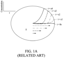
- FIG. 1A illustrates an example of a boundary level evolution with time of concentration of intercalation material in the electrode according to a related art.
- ⁇ from the center or R-y
- FIG. 1A rate of penetration may decrease over time (over time, penetration may take longer).
- RT room temperature
- LT low temperature
- FIG. 1C illustrates an example of a graph representing a comparison between actual and estimated voltage of a battery according to a related art.
- the accumulated SOC errors may lead to a substantial discrepancy between actual and calculated parameters like cell capacity.
- the voltage as calculated by existing ROM is less than or equal to 14% more than the voltage calculate by P2D.
- P2D refers to an actual profile of the battery
- ROM refers to an estimated profile of the battery (according to existing techniques).
- the LT attribute of an exponential decay in voltage at initial times is not captured in ROM.
- the boundary layer exists for a time t of 900 seconds or less, due to the very low diffusivity. This boundary layer is not addressed by present SPM formulations like ROM and the errors are magnified at lower temperatures.
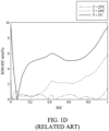
- FIG. 1D illustrates an example of a graph representing particle level SOC profiles as predicted by ROM according to a related art.
- the particle level SOC profiles as predicted by ROM and P2D, as shown in FIG. 1D show that ROM fails at low diffusion lengths.
- FIG. 1E illustrates an example of a graph representing comparison between actual and estimated SOC in anode and cathode according to a related art.
- the concentration profile inside the anode and cathode particles at initial times of 1C discharge for ROM and P2D are shown in FIG. 1E .
- cathode particles e.g., cathode particles of a size of 12 ⁇
- anode e.g., anode particles of a size of 7 ⁇
- the following describes a method and system for accurate estimation of SOC in low diffusivity.
- FIG. 2 illustrates an example of an electronic device (e.g., an electronic device 200) for detecting (predicting) short circuits in a battery.
- Examples of the electronic device 200 may include, but are not limited to, a computing device and a vehicle.
- the vehicle refers to any mode of transportation, delivery, or communication such as, for example, for example, an automobile, a truck, a tractor, a scooter, a motorcycle, a cycle, an amphibious vehicle, a snowmobile, a boat, a public transit vehicle, a bus, a monorail, a train, a tram, an autonomous vehicle, an unmanned aerial vehicle, a bicycle, a walking assist device (WAD), a robot, a drone, and a flying object such as an airplane.
- WAD walking assist device
- the vehicle may be, for example, an autonomous vehicle, a smart mobility, an electric vehicle, an intelligent vehicle, an electric vehicle (EV), a plug-in hybrid EV (PHEV), a hybrid EV (HEV), or a hybrid vehicle, an intelligent vehicle equipped with an advanced driver assistance system (ADAS) and/or an autonomous driving (AD) system.
- a smart mobility an electric vehicle, an intelligent vehicle, an electric vehicle (EV), a plug-in hybrid EV (PHEV), a hybrid EV (HEV), or a hybrid vehicle, an intelligent vehicle equipped with an advanced driver assistance system (ADAS) and/or an autonomous driving (AD) system.
- EV electric vehicle
- PHEV plug-in hybrid EV
- HEV hybrid EV
- ADAS advanced driver assistance system
- AD autonomous driving
- the electronic device 200 may also include, but is not limited to, a device, an apparatus or a system for estimating battery parameters in a rest period of an electric vehicle or a battery parameters estimation device for electric vehicles, or the like.
- the computing device may be implemented as, or in, various types of devices, such as, for example, a personal computer (PC), a data server, or a portable device.
- the portable device may be implemented as a laptop computer, a mobile phone, a smart phone, a tablet PC, a mobile internet device (MID), a personal digital assistant (PDA), an enterprise digital assistant (EDA), a digital still camera, a digital video camera, a portable multimedia player (PMP), a personal navigation device or portable navigation device (PND), or a smart device.
- the computing devices may be a wearable device, such as, for example, a smart watch and an apparatus for providing augmented reality (AR) (hereinafter simply referred to as an AR provision device) such as AR glasses, a head mounted display (HMD), various Internet of Things (IoT) devices that are controlled through a network, and other consumer electronics/information technology (CE/IT) devices.
- AR augmented reality
- HMD head mounted display
- IoT Internet of Things
- CE/IT consumer electronics/information technology
- the electronic device 200 may include a communicator 210, a memory 220, a processor 230, a battery management system (BMS) 240, and the battery 250.
- BMS battery management system
- the communicator 210 may be configured for communicating internally between the components of the electronic device 200 and external devices such as, for example, other wireless devices, computing devices, vehicles, printers, fax machines, and the like, via one or more networks.
- the memory 220 may store instructions to be executed by the processor 230.
- the memory 220 may store information used to determine the parameters.
- the memory 220 may store the sensing data, diffusion length of an intercalation material, threshold values, and the determined parameters.
- the memory 220 may store a program (or an application, or software) in the form of instructions.
- the stored program may be a set of syntaxes that are coded and executable by the processor 230 to operate the electronic device 200.
- the memory 220 may include a volatile memory or a non-volatile memory.
- the volatile memory may be implemented as a dynamic random-access memory (DRAM), a static random-access memory (SRAM), a thyristor RAM (T-RAM), a zero capacitor RAM (Z-RAM), or a twin transistor RAM (TTRAM).
- DRAM dynamic random-access memory
- SRAM static random-access memory
- T-RAM thyristor RAM
- Z-RAM zero capacitor RAM
- TTRAM twin transistor RAM
- the non-volatile memory may be implemented as an electrically erasable programmable read-only memory (EEPROM), a flash memory, a magnetic RAM (MRAM), a spin-transfer torque (STT)-MRAM, a conductive bridging RAM(CBRAM), a ferroelectric RAM (FeRAM), a phase change RAM (PRAM), a resistive RAM (RRAM), a nanotube RRAM, a polymer RAM (PoRAM), a nano floating gate Memory (NFGM), a holographic memory, a molecular electronic memory device), or an insulator resistance change memory. Further details regarding the memory 220 are provided below.
- EEPROM electrically erasable programmable read-only memory
- MRAM magnetic RAM
- STT spin-transfer torque
- CBRAM conductive bridging RAM
- FeRAM ferroelectric RAM
- PRAM phase change RAM
- RRAM resistive RAM
- NFGM nano floating gate Memory
- holographic memory a holographic memory
- the processor 230 may be configured to execute instructions stored in the memory 220 and to perform various operations.
- the processor 230 may control at least one other component of the electronic device 200 and perform processing of various pieces of data or computations.
- the processor 230 may control an overall operation of the electronic device 200 and may execute corresponding processor-readable instructions for performing operations of the electronic device 200.
- the processor 230 may execute, for example, software stored in the memory 220 to control one or more hardware components, such as, battery management system 240 of the electronic device 200 connected to the processor 230 and may perform various data processing or operations, and control of such components.
- the processor 230 may determine one or more parameters diffusion length of an intercalation material, compare the diffusion length to the threshold values, and calculate a concentration of the intercalation material in the electrode. In some examples, the processor 230 may determine whether the diffusion length is less than the threshold based on diffusivity of the intercalation material in the electrode, a value of a time variable, and a radius of the electrode. In some examples, the processor 230 may calculate the concentration of the intercalation material based on the calculated parameters. However, the operation of the processor 230 is not limited thereto, and the processor 230 may perform at least one of the operations described with reference to FIGS. 2 to 6 in parallel or in a time series.
- the processor 230 may be a single processing unit or several units, all of which could include multiple computing units.
- the processor 230 may be implemented as one or more microprocessors, microcomputers, microcontrollers, digital signal processors, central processing units, state machines, logic circuitries, and/or any devices that manipulate signals based on operational instructions.
- the processor 230 is configured to fetch and execute computer-readable instructions and data stored in the memory 220.
- the processor 230 may be a hardware-implemented data processing device.
- the hardware-implemented data processing device 230 may include, for example, a main processor (e.g., a central processing unit (CPU), a field-programmable gate array (FPGA), or an application processor (AP)) or an auxiliary processor (e.g., a GPU, a neural processing unit (NPU), an image signal processor (ISP), a sensor hub processor, or a communication processor (CP)) that is operable independently of, or in conjunction with the main processor. Further details regarding the processor 230 are provided below.
- a main processor e.g., a central processing unit (CPU), a field-programmable gate array (FPGA), or an application processor (AP)
- auxiliary processor e.g., a GPU, a neural processing unit (NPU), an image signal processor (ISP), a sensor hub processor, or a communication processor (CP)
- the memory 220 may be configured to store larger amounts of information than a memory 220.
- a non-transitory storage medium may store data that may, over time, change (e.g., in random access memory (RAM) or cache).
- the BMS 240 is coupled to the memory 220, the processor 230 and the battery 250.
- the BMS 240 may be an electronic system which manages the battery 250, for example, a rechargeable battery (a cell or the battery pack).
- the BMS 240 is configured to manage the charging and discharging of the battery 250, to provide notifications on a status of the battery 250 and also to provide critical safeguards to protect the battery 250 from damage, such as detection of a short circuit.
- the battery 250 may be the rechargeable battery.
- An example of the rechargeable battery may be a Lithium Ion battery (LIB).
- LIB Lithium Ion battery
- FIG. 2 illustrates hardware elements of the electronic device 200, it is to be understood that other embodiments are not limited thereto. In other embodiments, the electronic device 200 may include a smaller or greater number of elements. Further, the labels or names of the elements are used only for illustrative purposes and do not limit the scope of the present disclosure.
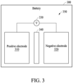
- FIG. 3 illustrates an example of a battery 300 of an electronic device.
- the battery 300 may include any battery that has a membrane (e.g., a separator) separating positive and negative electrodes (e.g., a lithium-ion battery, a lithium-polymer battery, etc.).
- the battery 300 may have a variety of shapes and sizes, depending on the shape and size of electronic device 200, the amount of power required by electronic device 200, etc.
- the battery 300 may include a positive electrode 310, a negative electrode 320, a voltage source 330, a separator 340, and/or an electrolyte 350.
- the battery 300 may provide power to components of the electronic device 200.
- positive electrode 310 may include an electrode through which positive electric current flows into a polarized electrical device.
- the positive electrode 310 may be made of a variety of shapes and sizes, depending on the shape and size of the battery 300, and may be made from a variety of materials.
- the negative electrode 320 may include an electrode through which positive electric current flows out of a polarized electrical device.
- the negative electrode 320 may be made of a variety of shapes and sizes, depending on the shape and size of the battery 300, and may be made from a variety of materials.
- the voltage source 330 may be used to charge the battery 300.
- the separator 340 may separate positive electrode 310 and negative electrode 320, and may include a membrane (e.g., a microporous membrane).
- the separator 340 may be made of a variety of shapes and sizes, depending on the shape and size of the battery 300.
- the electrolyte 350 may include any liquid substance which acts as a medium to conduct electricity between the positive electrode 310 and the negative electrode 320, and to store energy on the positive electrode 310 and the negative electrode 320.
- the electrolyte 350 may depend on the type and purpose of the battery 300.
- the battery 300 may be a lithium-ion battery.
- FIG. 3 shows exemplary components of the battery 300, in other implementations, the battery 300 may contain fewer, different, or additional components than depicted in FIG. 3 .
- an accurate SOC may be estimated for a low diffusivity condition in the battery 300.
- FIG. 4 illustrates an example of a method 400 for estimating battery parameters.
- the operations of FIG. 4 may be performed in the sequence and manner as shown. However, the order of some operations may be changed, or some of the operations may be omitted, without departing from the scope of the shown example. Additionally, operations illustrated in FIG. 4 may be performed in parallel or simultaneously.
- One or more blocks of FIG. 4 , and combinations of the blocks, can be implemented by special purpose hardware-based computer that perform the specified functions, or combinations of special purpose hardware and instructions, e.g., computer or processor instructions.
- operations 401 through 405 may be performed by a computing apparatus (e.g., processor 502 or the system 500 of FIG. 5 ).
- FIGS. 2-3 are also applicable to FIG. 4 and are incorporated herein.
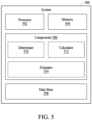
- FIG. 5 illustrates an example of a diagram of a system 500 for estimating battery parameters in a rest period.
- FIGS. 4 and 5 are explained in conjunction with each other.
- the system 500 may be a part of the BMS 240. In another example, the system 500 may be a part of the electronic device 200 and may be connected to the BMS 240.
- the system 500 may include, but is not limited to, a processor 502, memory 505, components 506, and data store 508. The components 506 and the memory 505 may be coupled to the processor 502.
- memory 220 and the processor 230 of FIG. 2 is also applicable to the processor 502 and the memory 504 of FIG. 5 , respectively, and are incorporated herein.
- the components 506 include routines, programs, objects, components, data structures, and the like, which perform particular tasks or implement data types.
- the components 506 may also be implemented as signal processor(s), state machine(s), logic circuitries, and/or any other device or component that manipulate signals based on operational instructions.
- the components 506 may be implemented in hardware, instructions executed by a processing unit, or by a combination thereof.
- the processing unit may include a computer, a processor, such as the processor 502, a state machine, a logic array, or any other suitable devices capable of processing instructions.
- the processing unit may be a general-purpose processor which executes instructions to cause the general-purpose processor to perform the required tasks or, the processing unit may be dedicated to performing the required functions.
- the components 506 may be machine-readable instructions (e.g., software) which, when executed by a processor or processing unit, perform any of the described functionalities.
- the components 506 may include a determiner 510, a calculator 512, and an estimator 514.
- the various components 510 to 514 may be in communication with each other.
- the various components 510 to 514 may be a part of the processor 502.
- the processor 502 may be configured to perform the functions of the components 510 to 514.
- the data store 508 serves, amongst other things, as a repository for storing data processed, received, and generated by one or more of the components 506.
- the processor 230 and memory 220 of the electronic device 200 may be coupled to the BMS 240 and may perform the functions of the processor 502 and memory 505 of the system 500.
- FIG. 4 illustrates an example of a method 400 for estimating battery parameters, in accordance with an example of the present disclosure.
- the parameters are estimated in initial times and/or low diffusivity and low temperature.
- Initial times and/or low diffusivity and low temperature refer to when ⁇ ( Dt ) « R , where D may denote low diffusivity, t may denote an initial time, and R may denote a radius of an electrode particle.
- method 400 may determine whether a diffusion length of an intercalation material in an electrode of a battery is less than a threshold.
- the threshold may be a measure of length that is used to determine the adequacy, or lack thereof, of the diffusion length of the intercalation material in the electrode of the battery.
- the threshold may be preset or set in advance.
- the diffusion length of the intercalation material is determined based on the diffusivity D of the intercalation material in the electrode, the value of the time variable t, and/or a radius R of the electrode.
- Whether the diffusion length of the intercalation material is less than the threshold may be determined based on the diffusivity D of the intercalation material in the electrode, the value of the time variable t, and/or the radius R of the electrode. For example, the determiner 510 may determine that the diffusion length is less than the threshold when a square root of a product of the diffusivity of the intercalation material and the value of the time variable is less than a product of the radius of the electrode and a coefficient less than 1.
- FIG. 6 illustrates an example of a diagram representing low diffusivity conditions.
- the diffusion length may be less than the threshold if the following condition is satisfied. ⁇ Dt ⁇ R
- the diffusion length may be less than the threshold if the following condition for both the electrodes, i.e., positive and negative electrodes, is satisfied. t ⁇ 0.04 R 2 / D
- the method 400 may include calculating a concentration C of the intercalation material in the electrode of the battery based on a result of the determination.
- the result of the determination may indicate that the diffusion length is less than the threshold.
- the parameters may include at least one of an equilibrium concentration C 0 of the intercalation material, a scaled concentration C* of the intercalation material, a reaction flux j, diffusivity D of the intercalation material in the electrode, or a value of a time variable t.
- the calculator 512 may calculate the parameters including the equilibrium concentration of the intercalation material, the scaled concentration of the intercalation material, the reaction flux, the diffusivity of the intercalation material in the electrode, and the value of the time variable when it is determined that the diffusion length is less than the threshold.
- the calculator 512 may calculate the concentration of the intercalation material based on the calculated parameters.
- the calculator 512 calculates the concentration C of the intercalation material in response to the determination that a diffusion length of each of the positive electrode 310 and the negative electrode 320 of the battery 300 is less than the threshold. Then, the calculator 512 may calculate the concentration C of the intercalation material using the below equation.
- C * C ⁇ C 0 j t D
- the calculator 512 may calculate a scaled concentration C* of the intercalation material based on a similarity variable ⁇ , using the below equation.
- C * ⁇ ⁇ + 2 ⁇ e ⁇ 2 4 + ⁇ erf ⁇ 2
- the calculator 512 may calculate the similarity variable ⁇ based on a thickness y of a boundary of the electrode, the diffusivity D of the intercalation material in the electrode, and/or the value of the time variable t.
- the calculator 512 may calculate the concentration C of the intercalation material using existing techniques.
- the method 400 includes estimating at least one battery parameter of the battery parameters based on the calculated concentration C of the intercalation material in the electrode.
- the battery parameters may include a state of health (SOH) of the battery 300, an SOC of the battery 300, electrochemical parameters of the battery 300, and a state of short (SOS) of the battery 300.
- the estimator 514 may estimate the SOC of the battery 300 using the open circuit voltage V and electrode time constant dependent logarithmic voltage profiles.
- the estimator 514 may estimate the electrochemical parameters (such as solid state diffusion, cell resistance, etc.) using the open circuit voltage V and electrode time constant dependent logarithmic voltage profiles.
- the estimator 514 may estimate at least one of the SOH or SOS of the battery 300 based on the estimated electrochemical parameters. For example, the estimator 514 may update the existing electrochemical parameter with the estimated electrochemical parameter to accurately estimate the SOH and/or SOS of battery 300.
- FIGS. 7A and 7B illustrate an example of a graph representing comparison between actual and estimated concentration profile of a battery.
- comparison between the estimated concentration profile of the positive electrode, i.e., anode, at different times is similar to an actual concentration profile of the positive electrode.
- the solid line curves show an actual concentration profile of the positive electrode, and the dotted curves show an estimated concentration profile of the positive electrode using the disclosed techniques.
- the concentration profile predicted by the disclosed technique is similar to the concentration profile of the positive electrode.
- FIG. 7B comparison between the estimated concentration profile of the negative electrode, i.e., cathode, at different times is similar to an actual concentration profile of the negative electrode.
- the solid line curves show the actual concentration profile of the negative electrode, and the dotted curves show the estimated concentration profile of the negative electrode using the disclosed techniques.
- the concentration profile predicted by the disclosed technique is similar to the concentration profile of the negative electrode.
- the computing apparatuses, the electronic devices, the processors, the memories, and other components described herein with respect to FIGS. 1-6 are implemented by or representative of hardware components.
- hardware components that may be used to perform the operations described in this application where appropriate include controllers, sensors, generators, drivers, memories, comparators, arithmetic logic units, adders, subtractors, multipliers, dividers, integrators, and any other electronic components configured to perform the operations described in this application.
- one or more of the hardware components that perform the operations described in this application are implemented by computing hardware, for example, by one or more processors or computers.
- a processor or computer may be implemented by one or more processing elements, such as an array of logic gates, a controller and an arithmetic logic unit, a digital signal processor, a microcomputer, a programmable logic controller, a field-programmable gate array, a programmable logic array, a microprocessor, or any other device or combination of devices that is configured to respond to and execute instructions in a defined manner to achieve a desired result.
- a processor or computer includes, or is connected to, one or more memories storing instructions or software that are executed by the processor or computer.
- Hardware components implemented by a processor or computer may execute instructions or software, such as an operating system (OS) and one or more software applications that run on the OS, to perform the operations described in this application.
- OS operating system
- the hardware components may also access, manipulate, process, create, and store data in response to execution of the instructions or software.
- processor or “computer” may be used in the description of the examples described in this application, but in other examples multiple processors or computers may be used, or a processor or computer may include multiple processing elements, or multiple types of processing elements, or both.
- a single hardware component or two or more hardware components may be implemented by a single processor, or two or more processors, or a processor and a controller.
- One or more hardware components may be implemented by one or more processors, or a processor and a controller, and one or more other hardware components may be implemented by one or more other processors, or another processor and another controller.
- One or more processors may implement a single hardware component, or two or more hardware components.
- a hardware component may have any one or more of different processing configurations, examples of which include a single processor, independent processors, parallel processors, single-instruction single-data (SISD) multiprocessing, single-instruction multiple-data (SIMD) multiprocessing, multiple-instruction single-data (MISD) multiprocessing, and multiple-instruction multiple-data (MIMD) multiprocessing.
- SISD single-instruction single-data
- SIMD single-instruction multiple-data
- MIMD multiple-instruction multiple-data
- a single operation or two or more operations may be performed by a single processor, or two or more processors, or a processor and a controller.
- One or more operations may be performed by one or more processors, or a processor and a controller, and one or more other operations may be performed by one or more other processors, or another processor and another controller.
- One or more processors, or a processor and a controller may perform a single operation, or two or more operations.
- Instructions or software to control computing hardware may be written as computer programs, code segments, instructions or any combination thereof, for individually or collectively instructing or configuring the one or more processors or computers to operate as a machine or special-purpose computer to perform the operations that are performed by the hardware components and the methods as described above.
- the instructions or software include machine code that is directly executed by the one or more processors or computers, such as machine code produced by a compiler.
- the instructions or software includes higher-level code that is executed by the one or more processors or computer using an interpreter.
- the instructions or software may be written using any programming language based on the block diagrams and the flow charts illustrated in the drawings and the corresponding descriptions herein, which disclose algorithms for performing the operations that are performed by the hardware components and the methods as described above.
- the instructions or software to control computing hardware for example, one or more processors or computers, to implement the hardware components and perform the methods as described above, and any associated data, data files, and data structures, may be recorded, stored, or fixed in or on one or more non-transitory computer-readable storage media.
- Examples of a non-transitory computer-readable storage medium include read-only memory (ROM), random-access programmable read only memory (PROM), electrically erasable programmable read-only memory (EEPROM), random-access memory (RAM), dynamic random access memory (DRAM), static random access memory (SRAM), flash memory, non-volatile memory, CD-ROMs, CD-Rs, CD+Rs, CD-RWs, CD+RWs, DVD-ROMs, DVD- Rs, DVD+Rs, DVD-RWs, DVD+RWs, DVD-RAMs, BD-ROMs, BD-Rs, BD-R LTHs, BD-Res, blue-ray or optical disk storage, hard disk drive (HDD), solid state drive (SSD), flash memory, a card type memory such as multimedia card micro or a card (for example, secure digital (SD) or extreme digital (XD)), magnetic tapes, floppy disks, magneto-optical data storage devices, optical data storage devices, hard disks, solid
- the instructions or software and any associated data, data files, and data structures are distributed over network-coupled computer systems so that the instructions and software and any associated data, data files, and data structures are stored, accessed, and executed in a distributed fashion by the one or more processors or computers.
Landscapes
- Physics & Mathematics (AREA)
- General Physics & Mathematics (AREA)
- Engineering & Computer Science (AREA)
- Chemical & Material Sciences (AREA)
- Manufacturing & Machinery (AREA)
- Chemical Kinetics & Catalysis (AREA)
- Electrochemistry (AREA)
- General Chemical & Material Sciences (AREA)
- Materials Engineering (AREA)
- Secondary Cells (AREA)
Abstract
Description
- The present disclosure relates to a method and an electronic device for estimating battery parameters.
- Generally, there are many consumers for wireless devices such as mobile phones, laptops, tablets, smart watches, and the like. Usually, a rechargeable battery (e.g., a lithium (Li) ion battery) provides portable electricity and power to such wireless devices. Electric vehicles are also operated using electrical energy stored in the rechargeable battery. However, the battery degrades due to usage and the passage of time, which leads to losses. Thus, the useful, extractable power of the battery decreases over a period of time. Hence, precise state of charge (SOC) estimation facilitates an effective battery management system (BMS).
- Single Particle Models (SPM) are popularly used for state estimation due to their accuracy, speed, and computational efficiency. But the accuracy of the SOC estimated by an SPM generally suffers under low characteristic diffusivity length conditions as the profile approximations used fail and are invalid. For example, existing SPM under Low diffusion lengths (like low temperatures/initial times) conditions have an accumulated SOC error that may be greater than 20% for a single discharge. Such erroneous SOC estimates may lead to problems like over discharge, accelerated ageing, short circuits, and the like.
- This Summary is provided to introduce a selection of concepts in a simplified form that are further described below in the Detailed Description. This Summary is not intended to identify key features or essential features of the claimed subject matter, nor is it intended to be used as an aid in determining the scope of the claimed subject matter.
- The invention is claimed in the independent claims. Preferred embodiments are specified in the dependent claims.
- In one general aspect, there is provided a method of estimating battery parameters performed by a processor, the method including determining whether a diffusion length of an intercalation material in an electrode of a battery is lesser than a threshold, calculating a concentration of the intercalation material in the electrode based on a result of the determination, and estimating at least one battery parameter of the battery parameters based on the concentration of the intercalation material.
- The determining of whether the diffusion length of the intercalation material is lesser than the threshold may include determining whether the diffusion length is lesser than the threshold based on a diffusivity of the intercalation material in the electrode, a value of a time variable, and a radius of the electrode.
- The determining of whether the diffusion length of the intercalation material is lesser than the threshold may include determining that the diffusion length is lesser than the threshold in response to a square root of a product of a diffusivity of the intercalation material and a value of a time variable being lesser than a product of a radius of the electrode and a coefficient less than 1.
- The calculating of the concentration of the intercalation material may include calculating parameters comprising an equilibrium concentration of the intercalation material, a scaled concentration of the intercalation material, a reaction flux, a diffusivity of the intercalation material in the electrode, and a value of a time variable, in response to the diffusion length of the intercalation material being lesser than the threshold, and calculating a concentration of the intercalation material based on the parameters.
- The calculating of the concentration of the intercalation material may include calculating a scaled concentration of the intercalation material based on a similarity variable.
- The calculating of the scaled concentration may include calculating the similarity variable based on a thickness of a boundary of the electrode, a diffusivity of the intercalation material in the electrode, and a value of a time variable.
- The estimating of the at least one battery parameter may include estimating at least one of a state of health of the battery, a state of charge of the battery, electrochemical parameters of the battery, or a state of short of the battery.
- The estimating of the at least one battery parameter may include estimating at least one of a state of charge of the battery or electrochemical parameters of the battery based on an open circuit voltage and electrode time constant dependent logarithmic voltage profiles.
- The estimating of the at least one battery parameter may include estimating electrochemical parameters of the battery, and estimating at least one of a state of health of the battery or a state of short of the battery based on the electrochemical parameters.
- In another general aspect, there is provided an electronic device for estimating battery parameters, the electronic device including a processor configured to determine whether a diffusion length of an intercalation material in an electrode of a battery is less than a threshold, calculate a concentration of the intercalation material in the electrode based on a result of the determination, and estimate at least one battery parameter of the battery parameters based on the concentration of the intercalation material.
- The processor may be configured to determine whether the diffusion length is lesser than the threshold based on a diffusivity of the intercalation material in the electrode, a value of a time variable, and a radius of the electrode.
- The processor may be configured to determine that the diffusion length is lesser than the threshold in response to a square root of a product of a diffusivity of the intercalation material and a value of a time variable being lesser than a product of a radius of the electrode and a coefficient less than 1.
- The processor may be configured to calculate parameters comprising an equilibrium concentration of the intercalation material, a scaled concentration of the intercalation material, a reaction flux, a diffusivity of the intercalation material in the electrode, and a value of a time variable, in response to the diffusion length of the intercalation material being lesser than a predetermined threshold, and calculate a concentration of the intercalation material based on the parameters.
- The processor may be configured to calculate a scaled concentration of the intercalation material based on a similarity variable.
- The processor may be configured to calculate the similarity variable based on a thickness of a boundary of the electrode, a diffusivity of the intercalation material, and a value of a time variable.
- The processor may be configured to estimate at least one of a state of health of the battery, a state of charge of the battery, electrochemical parameters of the battery, or a state of short of the battery.
- The processor may be configured to estimate at least one of a state of charge of the battery or electrochemical parameters of the battery based on an open circuit voltage and electrode time constant dependent logarithmic voltage profiles.
- The processor may be configured to estimate electrochemical parameters of the battery, and estimate at least one of a state of health of the battery or a state of short of the battery based on the electrochemical parameters.
- The processor may be configured to calculate the concentration of the intercalation material in the electrode, in response to a diffusion length of a positive electrode and a negative electrode of the battery being lesser than the threshold.
- Other features and aspects will be apparent from the following detailed description, the drawings, and the claims.
-
-
FIG. 1A illustrates an example of a boundary level evolution with time of concentration of intercalation material in the electrode according to a related art. -
FIG. 1B illustrates an example of a graph representing change in diffusivity with respect to temperature according to a related art. -
FIG. 1C illustrates an example of a graph representing comparison between actual and estimated voltage of a battery according to a related art. -
FIG. 1D illustrates an example of a graph representing particle level SOC profiles as predicted by reduced order model (ROM) according to a related art. -
FIG. 1E illustrates an example of a graph representing comparison between actual and estimated state of charge (SOC) in anode and cathode according to a related art. -
FIG. 2 illustrates an example of a wireless device for estimating battery parameters. -
FIG. 3 illustrates an example of a battery of a wireless device. -
FIG. 4 illustrates an example of a method estimating battery parameters. -
FIG. 5 illustrates an example of a system for estimating battery parameters. -
FIG. 6 illustrates an example of a diagram representing low diffusivity condition. -
FIGS. 7A and7B illustrate an example of a graph representing comparison between actual and estimated concentration profiles of a battery. - Throughout the drawings and the detailed description, unless otherwise described or provided, it shall be understood that the same or like drawing reference numerals refer to the same or like elements, features, and structures. The drawings may not be to scale, and the relative size, proportions, and depiction of elements in the drawings may be exaggerated for clarity, illustration, and convenience.
- The following detailed description is provided to assist the reader in gaining a comprehensive understanding of the methods, apparatuses, and/or systems described herein. However, various changes, modifications, and equivalents of the methods, apparatuses, and/or systems described herein will be apparent after an understanding of the disclosure of this application. For example, the sequences of operations described herein are merely examples, and are not limited to those set forth herein, but may be changed as will be apparent after an understanding of the disclosure of this application, with the exception of operations necessarily occurring in a certain order. Also, descriptions of features that are known after an understanding of the disclosure of this application may be omitted for increased clarity and conciseness.
- The features described herein may be embodied in different forms and are not to be construed as being limited to the examples described herein. Rather, the examples described herein have been provided merely to illustrate some of the many possible ways of implementing the methods, apparatuses, and/or systems described herein that will be apparent after an understanding of the disclosure of this application.
- Although terms such as "first," "second," and "third", or A, B, (a), (b), and the like may be used herein to describe various members, components, regions, layers, portions, or sections, these members, components, regions, layers, portions, or sections are not to be limited by these terms. Each of these terminologies is not used to define an essence, order, or sequence of corresponding members, components, regions, layers, portions, or sections, for example, but used merely to distinguish the corresponding members, components, regions, layers, portions, or sections from other members, components, regions, layers, portions, or sections. Thus, a first member, component, region, layer, portions, or section referred to in the examples described herein may also be referred to as a second member, component, region, layer, portions, or section without departing from the teachings of the examples.
- Throughout the specification, when a component or element is described as being "connected to," "coupled to," or "joined to" another component or element, it may be directly "connected to," "coupled to," or "joined to" the other component or element, or there may reasonably be one or more other components or elements intervening therebetween. When a component or element is described as being "directly connected to," "directly coupled to," or "directly joined to" another component or element, there can be no other elements intervening therebetween. Likewise, expressions, for example, "between" and "immediately between" and "adjacent to" and "immediately adjacent to" may also be construed as described in the foregoing. As used herein, the term "and/or" includes any and all combinations of one or more of the associated listed items. For example, "A and/or B" may be interpreted as "A," "B," or "A and B."
- The terminology used herein is for the purpose of describing particular examples only and is not to be limiting of the examples. The singular forms "a," "an," and "the" are intended to include the plural forms as well, unless the context clearly indicates otherwise. It will be further understood that the terms "comprises/comprising" and/or "includes/including" when used herein, specify the presence of stated features, integers, steps, operations, elements, and/or components, but do not preclude the presence or addition of one or more other features, integers, steps, operations, elements, components and/or groups thereof.
-
FIG. 1A illustrates an example of a boundary level evolution with time of concentration of intercalation material in the electrode according to a related art. When a flux is applied at surface of the electrode, the concentration penetrates to a distance but does not reach the center. This distance that the concentration penetrates is called boundary layer, δ (from the center or R-y) and evolves with time as shown inFIG. 1A . As can be seen inFIG. 1A , rate of penetration may decrease over time (over time, penetration may take longer). -
FIG. 1B illustrates an example of a graph representing change in diffusivity with respect to temperature according to a related art. As shown inFIG. 1B , this distance is plotted as a fraction of the total radius for different diffusivities (diffusivities respectively corresponding to high, room, and low temperatures, from left to right) with time. As may be seen fromFIG. 1B , it takes easily 40 to 60 seconds at room temperature (RT), for example, when the temperature is between 10°C and 35°C, and 1000 seconds or less at low temperature (LT), for example, when the temperature is less than 10°C, for the flux to reach the particle center (e.g., when δ = 0 or y =R). Only after this are normal conservation equations and profile approximations likely to be valid. Thus, when √( Dt )« R, an alternate approach is needed, else leading to erroneous SOC profiles for times up to 1000 seconds at less than or equal to 5°C, where D denotes low diffusivities, T denotes an initial time, R denotes a radius of an electrode particle, and y denotes a boundary layer thickness. -
FIG. 1C illustrates an example of a graph representing a comparison between actual and estimated voltage of a battery according to a related art. The accumulated SOC errors may lead to a substantial discrepancy between actual and calculated parameters like cell capacity. The full order pseudo-two-dimensional (P2D) and reduced order model (ROM) 1C discharge capacities for the same cell parameters at a Ds = 10-13 m2/s (T= 25°C) and 10-14 (T=5°C) is shown inFIG. 1C . As may be seen fromFIG. 1C , the voltage as calculated by existing ROM is less than or equal to 14% more than the voltage calculate by P2D. In an example, P2D refers to an actual profile of the battery and ROM refers to an estimated profile of the battery (according to existing techniques). Also, the LT attribute of an exponential decay in voltage at initial times is not captured in ROM. - At RT (room temperature) or temperature of 25°C, the boundary layer exists for only t=60 seconds after which the flux reaches the center and profile approximations work. In another example, at a temperature of -5°C, the boundary layer exists for a time t of 900 seconds or less, due to the very low diffusivity. This boundary layer is not addressed by present SPM formulations like ROM and the errors are magnified at lower temperatures.
-
FIG. 1D illustrates an example of a graph representing particle level SOC profiles as predicted by ROM according to a related art. The particle level SOC profiles as predicted by ROM and P2D, as shown inFIG. 1D , during the existence of the boundary layer show that ROM fails at low diffusion lengths. -
FIG. 1E illustrates an example of a graph representing comparison between actual and estimated SOC in anode and cathode according to a related art. Even though the discharge capacity at RT seems to match between ROM and P2D, on close inspection of particle level SOC and concentration profiles, it may be observed that there are major issues with ROM predictions and its assumptions. The concentration profile inside the anode and cathode particles at initial times of 1C discharge for ROM and P2D are shown inFIG. 1E . The ROM profiles deviate considerably from the corresponding P2D profiles for t < 20 seconds for anode and t < 60 seconds for cathode. This corresponds to exactly t=(0.01R^2)/D. As cathode particles (e.g., cathode particles of a size of 12 µ) are larger than anode (e.g., anode particles of a size of 7 µ), it takes longer for the flux to reach the particle center in the cathode than the particle center in the anode. This takes up to 1000 seconds at low diffusivities (e.g., diffusivity of 10-14.5). Not only are the profiles not matching, but the ROM profiles greatly differ at times. For example: the cathode profile at t=7 seconds and t=15 seconds in ROM, implies that there is another source of flux inside the particle causing the reversal of profile shape inside the particle (e.g., a decrease and increase) to happen. - Thus, for initial times and/or low temperatures, i.e., √( Dt )« R, the ROM formulations, profile approximations, and SOC calculations are incorrect leading to serious lapses like erroneous capacity calculations, over charge (over discharge), unexpected shut down ultimately leading to health and safety issues like aging and shorting, and the like.
- Hence, there is a need for accurate estimation of SOC in low diffusivity. Accordingly, the following describes provides a method and system for accurate estimation of SOC in low diffusivity.
-
FIG. 2 illustrates an example of an electronic device (e.g., an electronic device 200) for detecting (predicting) short circuits in a battery. Examples of theelectronic device 200 may include, but are not limited to, a computing device and a vehicle. - In some examples, the vehicle refers to any mode of transportation, delivery, or communication such as, for example, for example, an automobile, a truck, a tractor, a scooter, a motorcycle, a cycle, an amphibious vehicle, a snowmobile, a boat, a public transit vehicle, a bus, a monorail, a train, a tram, an autonomous vehicle, an unmanned aerial vehicle, a bicycle, a walking assist device (WAD), a robot, a drone, and a flying object such as an airplane. In some examples, the vehicle may be, for example, an autonomous vehicle, a smart mobility, an electric vehicle, an intelligent vehicle, an electric vehicle (EV), a plug-in hybrid EV (PHEV), a hybrid EV (HEV), or a hybrid vehicle, an intelligent vehicle equipped with an advanced driver assistance system (ADAS) and/or an autonomous driving (AD) system.
- The
electronic device 200 may also include, but is not limited to, a device, an apparatus or a system for estimating battery parameters in a rest period of an electric vehicle or a battery parameters estimation device for electric vehicles, or the like. - In some examples, the computing device may be implemented as, or in, various types of devices, such as, for example, a personal computer (PC), a data server, or a portable device. In an example, the portable device may be implemented as a laptop computer, a mobile phone, a smart phone, a tablet PC, a mobile internet device (MID), a personal digital assistant (PDA), an enterprise digital assistant (EDA), a digital still camera, a digital video camera, a portable multimedia player (PMP), a personal navigation device or portable navigation device (PND), or a smart device. In an example, the computing devices may be a wearable device, such as, for example, a smart watch and an apparatus for providing augmented reality (AR) (hereinafter simply referred to as an AR provision device) such as AR glasses, a head mounted display (HMD), various Internet of Things (IoT) devices that are controlled through a network, and other consumer electronics/information technology (CE/IT) devices.
- Referring to
FIG. 2 , theelectronic device 200 may include acommunicator 210, amemory 220, aprocessor 230, a battery management system (BMS) 240, and thebattery 250. - The
communicator 210 may be configured for communicating internally between the components of theelectronic device 200 and external devices such as, for example, other wireless devices, computing devices, vehicles, printers, fax machines, and the like, via one or more networks. Thememory 220 may store instructions to be executed by theprocessor 230. - The
memory 220 may store information used to determine the parameters. For example, thememory 220 may store the sensing data, diffusion length of an intercalation material, threshold values, and the determined parameters. However, this is only an example, and the information stored in thememory 220 is not limited thereto. In an example, thememory 220 may store a program (or an application, or software) in the form of instructions. The stored program may be a set of syntaxes that are coded and executable by theprocessor 230 to operate theelectronic device 200. Thememory 220 may include a volatile memory or a non-volatile memory. - The volatile memory may be implemented as a dynamic random-access memory (DRAM), a static random-access memory (SRAM), a thyristor RAM (T-RAM), a zero capacitor RAM (Z-RAM), or a twin transistor RAM (TTRAM).
- The non-volatile memory may be implemented as an electrically erasable programmable read-only memory (EEPROM), a flash memory, a magnetic RAM (MRAM), a spin-transfer torque (STT)-MRAM, a conductive bridging RAM(CBRAM), a ferroelectric RAM (FeRAM), a phase change RAM (PRAM), a resistive RAM (RRAM), a nanotube RRAM, a polymer RAM (PoRAM), a nano floating gate Memory (NFGM), a holographic memory, a molecular electronic memory device), or an insulator resistance change memory. Further details regarding the
memory 220 are provided below. - The
processor 230 may be configured to execute instructions stored in thememory 220 and to perform various operations. Theprocessor 230 may control at least one other component of theelectronic device 200 and perform processing of various pieces of data or computations. Theprocessor 230 may control an overall operation of theelectronic device 200 and may execute corresponding processor-readable instructions for performing operations of theelectronic device 200. Theprocessor 230 may execute, for example, software stored in thememory 220 to control one or more hardware components, such as, battery management system 240 of theelectronic device 200 connected to theprocessor 230 and may perform various data processing or operations, and control of such components. - The
processor 230 may determine one or more parameters diffusion length of an intercalation material, compare the diffusion length to the threshold values, and calculate a concentration of the intercalation material in the electrode. In some examples, theprocessor 230 may determine whether the diffusion length is less than the threshold based on diffusivity of the intercalation material in the electrode, a value of a time variable, and a radius of the electrode. In some examples, theprocessor 230 may calculate the concentration of the intercalation material based on the calculated parameters. However, the operation of theprocessor 230 is not limited thereto, and theprocessor 230 may perform at least one of the operations described with reference toFIGS. 2 to 6 in parallel or in a time series. - The
processor 230 may be a single processing unit or several units, all of which could include multiple computing units. Theprocessor 230 may be implemented as one or more microprocessors, microcomputers, microcontrollers, digital signal processors, central processing units, state machines, logic circuitries, and/or any devices that manipulate signals based on operational instructions. Among other capabilities, theprocessor 230 is configured to fetch and execute computer-readable instructions and data stored in thememory 220. - The
processor 230 may be a hardware-implemented data processing device. The hardware-implementeddata processing device 230 may include, for example, a main processor (e.g., a central processing unit (CPU), a field-programmable gate array (FPGA), or an application processor (AP)) or an auxiliary processor (e.g., a GPU, a neural processing unit (NPU), an image signal processor (ISP), a sensor hub processor, or a communication processor (CP)) that is operable independently of, or in conjunction with the main processor. Further details regarding theprocessor 230 are provided below. - In some examples, the
memory 220 may be configured to store larger amounts of information than amemory 220. In certain examples, a non-transitory storage medium may store data that may, over time, change (e.g., in random access memory (RAM) or cache). - The BMS 240 is coupled to the
memory 220, theprocessor 230 and thebattery 250. The BMS 240 may be an electronic system which manages thebattery 250, for example, a rechargeable battery (a cell or the battery pack). The BMS 240 is configured to manage the charging and discharging of thebattery 250, to provide notifications on a status of thebattery 250 and also to provide critical safeguards to protect thebattery 250 from damage, such as detection of a short circuit. Thebattery 250 may be the rechargeable battery. An example of the rechargeable battery may be a Lithium Ion battery (LIB). - Although,
FIG. 2 illustrates hardware elements of theelectronic device 200, it is to be understood that other embodiments are not limited thereto. In other embodiments, theelectronic device 200 may include a smaller or greater number of elements. Further, the labels or names of the elements are used only for illustrative purposes and do not limit the scope of the present disclosure. -
FIG. 3 illustrates an example of abattery 300 of an electronic device. Thebattery 300 may include any battery that has a membrane (e.g., a separator) separating positive and negative electrodes (e.g., a lithium-ion battery, a lithium-polymer battery, etc.). Thebattery 300 may have a variety of shapes and sizes, depending on the shape and size ofelectronic device 200, the amount of power required byelectronic device 200, etc. As illustrated inFIG. 2 , thebattery 300 may include apositive electrode 310, anegative electrode 320, avoltage source 330, aseparator 340, and/or anelectrolyte 350. In some examples, thebattery 300 may provide power to components of theelectronic device 200. - In some examples,
positive electrode 310 may include an electrode through which positive electric current flows into a polarized electrical device. Thepositive electrode 310 may be made of a variety of shapes and sizes, depending on the shape and size of thebattery 300, and may be made from a variety of materials. - The
negative electrode 320 may include an electrode through which positive electric current flows out of a polarized electrical device. Thenegative electrode 320 may be made of a variety of shapes and sizes, depending on the shape and size of thebattery 300, and may be made from a variety of materials. - The
voltage source 330 may be used to charge thebattery 300. - The
separator 340 may separatepositive electrode 310 andnegative electrode 320, and may include a membrane (e.g., a microporous membrane). Theseparator 340 may be made of a variety of shapes and sizes, depending on the shape and size of thebattery 300. - The
electrolyte 350 may include any liquid substance which acts as a medium to conduct electricity between thepositive electrode 310 and thenegative electrode 320, and to store energy on thepositive electrode 310 and thenegative electrode 320. Theelectrolyte 350 may depend on the type and purpose of thebattery 300. - In some examples, the
battery 300 may be a lithium-ion battery. AlthoughFIG. 3 shows exemplary components of thebattery 300, in other implementations, thebattery 300 may contain fewer, different, or additional components than depicted inFIG. 3 . - In order to prevent any health and safety issues associated with short circuits of the
battery 300, in some examples described below in connection withFIGS. 4 to 7B , an accurate SOC may be estimated for a low diffusivity condition in thebattery 300. -
FIG. 4 illustrates an example of amethod 400 for estimating battery parameters. The operations ofFIG. 4 may be performed in the sequence and manner as shown. However, the order of some operations may be changed, or some of the operations may be omitted, without departing from the scope of the shown example. Additionally, operations illustrated inFIG. 4 may be performed in parallel or simultaneously. One or more blocks ofFIG. 4 , and combinations of the blocks, can be implemented by special purpose hardware-based computer that perform the specified functions, or combinations of special purpose hardware and instructions, e.g., computer or processor instructions. For example,operations 401 through 405 may be performed by a computing apparatus (e.g.,processor 502 or thesystem 500 ofFIG. 5 ). In addition to the description ofFIG. 4 below, the descriptions ofFIGS. 2-3 are also applicable toFIG. 4 and are incorporated herein. -
FIG. 5 illustrates an example of a diagram of asystem 500 for estimating battery parameters in a rest period. For the sake of brevity, the descriptions of theFIGS. 4 and5 are explained in conjunction with each other. - In some examples, the
system 500 may be a part of the BMS 240. In another example, thesystem 500 may be a part of theelectronic device 200 and may be connected to the BMS 240. Thesystem 500 may include, but is not limited to, aprocessor 502, memory 505,components 506, anddata store 508. Thecomponents 506 and the memory 505 may be coupled to theprocessor 502. - The description of
memory 220 and theprocessor 230 ofFIG. 2 is also applicable to theprocessor 502 and thememory 504 ofFIG. 5 , respectively, and are incorporated herein. - The
components 506, amongst other things, include routines, programs, objects, components, data structures, and the like, which perform particular tasks or implement data types. Thecomponents 506 may also be implemented as signal processor(s), state machine(s), logic circuitries, and/or any other device or component that manipulate signals based on operational instructions. - Furthermore, the
components 506 may be implemented in hardware, instructions executed by a processing unit, or by a combination thereof. The processing unit may include a computer, a processor, such as theprocessor 502, a state machine, a logic array, or any other suitable devices capable of processing instructions. The processing unit may be a general-purpose processor which executes instructions to cause the general-purpose processor to perform the required tasks or, the processing unit may be dedicated to performing the required functions. In another example of the present disclosure, thecomponents 506 may be machine-readable instructions (e.g., software) which, when executed by a processor or processing unit, perform any of the described functionalities. - In an example, the
components 506 may include adeterminer 510, acalculator 512, and anestimator 514. - The
various components 510 to 514 may be in communication with each other. In an example, thevarious components 510 to 514 may be a part of theprocessor 502. In another example, theprocessor 502 may be configured to perform the functions of thecomponents 510 to 514. Thedata store 508 serves, amongst other things, as a repository for storing data processed, received, and generated by one or more of thecomponents 506. - In an example, the
processor 230 andmemory 220 of theelectronic device 200 may be coupled to the BMS 240 and may perform the functions of theprocessor 502 and memory 505 of thesystem 500. -
FIG. 4 illustrates an example of amethod 400 for estimating battery parameters, in accordance with an example of the present disclosure. In an example, the parameters are estimated in initial times and/or low diffusivity and low temperature. Initial times and/or low diffusivity and low temperature refer to when √( Dt )« R , where D may denote low diffusivity, t may denote an initial time, and R may denote a radius of an electrode particle. - Referring back to
FIG. 4 , inoperation 401,method 400 may determine whether a diffusion length of an intercalation material in an electrode of a battery is less than a threshold. In an example, the threshold may be a measure of length that is used to determine the adequacy, or lack thereof, of the diffusion length of the intercalation material in the electrode of the battery. In an example, the threshold may be preset or set in advance. In an example, the diffusion length of the intercalation material is determined based on the diffusivity D of the intercalation material in the electrode, the value of the time variable t, and/or a radius R of the electrode. Whether the diffusion length of the intercalation material is less than the threshold may be determined based on the diffusivity D of the intercalation material in the electrode, the value of the time variable t, and/or the radius R of the electrode. For example, thedeterminer 510 may determine that the diffusion length is less than the threshold when a square root of a product of the diffusivity of the intercalation material and the value of the time variable is less than a product of the radius of the electrode and a coefficient less than 1. -
FIG. 6 illustrates an example of a diagram representing low diffusivity conditions. For example, the diffusion length may be less than the threshold if the following condition is satisfied.
- When the condition that √Dt«R is satisfied, the concentration gradient due to the surface flux is confined to a boundary layer, y (=R-r), as shown in
FIG. 6 . Variable "r" is the radial distance from the center of the particle. Accordingly, the spherical coordinate mass conservation equations and boundary conditions are modified to reflect the presence and solve for the concentration profile inside this boundary layer. Due to the center of the particle being quite distant from the surface during this phase, a similarity solution is disclosed leading to a concentration profile in the spatial and temporal dimensions. - For example, in another example, the diffusion length may be less than the threshold if the following condition for both the electrodes, i.e., positive and negative electrodes, is satisfied.

- In
Equation 2, t is the value of the time variable, R is the radius of an electrode, and D is the diffusivity of the intercalation material in the electrode. Thereafter, inoperation 403, themethod 400 may include calculating a concentration C of the intercalation material in the electrode of the battery based on a result of the determination. In an example, the result of the determination may indicate that the diffusion length is less than the threshold. In an example, the parameters may include at least one of an equilibrium concentration C0 of the intercalation material, a scaled concentration C* of the intercalation material, a reaction flux j, diffusivity D of the intercalation material in the electrode, or a value of a time variable t. For example, thecalculator 512 may calculate the parameters including the equilibrium concentration of the intercalation material, the scaled concentration of the intercalation material, the reaction flux, the diffusivity of the intercalation material in the electrode, and the value of the time variable when it is determined that the diffusion length is less than the threshold. Thecalculator 512 may calculate the concentration of the intercalation material based on the calculated parameters. In some examples, thecalculator 512 calculates the concentration C of the intercalation material in response to the determination that a diffusion length of each of thepositive electrode 310 and thenegative electrode 320 of thebattery 300 is less than the threshold. Then, thecalculator 512 may calculate the concentration C of the intercalation material using the below equation.
- In
equation 3, scaled concentration C* of the intercalation material, c is the concentration of the intercalation material, Co is the equilibrium concentration of the intercalation material, D is the diffusivity of the intercalation material in the electrode, j is the reaction flux, and t is the value of the time variable. Further, thecalculator 512 may calculate a scaled concentration C* of the intercalation material based on a similarity variable ξ, using the below equation.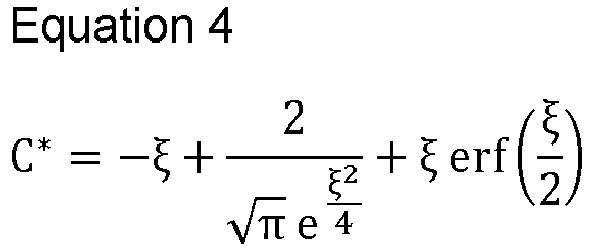
- In an example, the
calculator 512 may calculate the similarity variable ξ based on a thickness y of a boundary of the electrode, the diffusivity D of the intercalation material in the electrode, and/or the value of the time variable t. Thecalculator 512 may calculate the similarity variable ξ using the below equation.
- Referring back to
operation 401, if thedeterminer 510 determines that the intercalation flux J of thebattery 300 does not satisfy the preset condition, then thecalculator 512 may calculate the concentration C of the intercalation material using existing techniques. - Referring to
FIG. 4 , inoperation 405, themethod 400 includes estimating at least one battery parameter of the battery parameters based on the calculated concentration C of the intercalation material in the electrode. In an example, the battery parameters may include a state of health (SOH) of thebattery 300, an SOC of thebattery 300, electrochemical parameters of thebattery 300, and a state of short (SOS) of thebattery 300. In some examples, theestimator 514 may estimate the SOC of thebattery 300 using the open circuit voltage V and electrode time constant dependent logarithmic voltage profiles. Similarly, theestimator 514 may estimate the electrochemical parameters (such as solid state diffusion, cell resistance, etc.) using the open circuit voltage V and electrode time constant dependent logarithmic voltage profiles. In addition, theestimator 514 may estimate at least one of the SOH or SOS of thebattery 300 based on the estimated electrochemical parameters. For example, theestimator 514 may update the existing electrochemical parameter with the estimated electrochemical parameter to accurately estimate the SOH and/or SOS ofbattery 300. -
FIGS. 7A and7B illustrate an example of a graph representing comparison between actual and estimated concentration profile of a battery. InFIG. 7A , comparison between the estimated concentration profile of the positive electrode, i.e., anode, at different times is similar to an actual concentration profile of the positive electrode. The solid line curves show an actual concentration profile of the positive electrode, and the dotted curves show an estimated concentration profile of the positive electrode using the disclosed techniques. As clearly shown inFIG. 7A , the concentration profile predicted by the disclosed technique is similar to the concentration profile of the positive electrode. - Similarly, in
FIG. 7B , comparison between the estimated concentration profile of the negative electrode, i.e., cathode, at different times is similar to an actual concentration profile of the negative electrode. The solid line curves show the actual concentration profile of the negative electrode, and the dotted curves show the estimated concentration profile of the negative electrode using the disclosed techniques. As clearly shown inFIG. 7B , the concentration profile predicted by the disclosed technique is similar to the concentration profile of the negative electrode. - Thus, the disclosed techniques provide one or more of the following advantages:
- 1) more accurate estimation of SOC of a battery in low diffusivity;
- 2) more accurate estimation of SOC of a battery at low temperature;
- 3) more accurate estimation of SOC of a battery with a large particle radius;
- 4) more accurate estimation of SOH of the battery; and
- 5) safer batteries by avoiding over-charge/over-discharge to avoid short circuits.
- The drawings and the forgoing description give examples of embodiments. Those skilled in the art will appreciate that one or more of the described elements may well be combined into a single functional element. In another example, certain elements may be split into multiple functional elements. Elements from one embodiment may be added to another embodiment. For example, orders of processes described herein may be changed and are not limited to the manner described herein.
- The scope of the embodiments is by no means limited by these specific examples. Numerous variations, whether explicitly given in the specification or not, such as differences in structure, dimension, and use of material, are possible. The scope of embodiments is at least as broad as is given by the following claims.
- Disclosed above are quick and accurate SOC estimation methods and apparatuses for addressing low characteristic diffusivity lengths for BMS.
- The computing apparatuses, the electronic devices, the processors, the memories, and other components described herein with respect to
FIGS. 1-6 are implemented by or representative of hardware components. Examples of hardware components that may be used to perform the operations described in this application where appropriate include controllers, sensors, generators, drivers, memories, comparators, arithmetic logic units, adders, subtractors, multipliers, dividers, integrators, and any other electronic components configured to perform the operations described in this application. In other examples, one or more of the hardware components that perform the operations described in this application are implemented by computing hardware, for example, by one or more processors or computers. A processor or computer may be implemented by one or more processing elements, such as an array of logic gates, a controller and an arithmetic logic unit, a digital signal processor, a microcomputer, a programmable logic controller, a field-programmable gate array, a programmable logic array, a microprocessor, or any other device or combination of devices that is configured to respond to and execute instructions in a defined manner to achieve a desired result. In one example, a processor or computer includes, or is connected to, one or more memories storing instructions or software that are executed by the processor or computer. Hardware components implemented by a processor or computer may execute instructions or software, such as an operating system (OS) and one or more software applications that run on the OS, to perform the operations described in this application. The hardware components may also access, manipulate, process, create, and store data in response to execution of the instructions or software. For simplicity, the singular term "processor" or "computer" may be used in the description of the examples described in this application, but in other examples multiple processors or computers may be used, or a processor or computer may include multiple processing elements, or multiple types of processing elements, or both. For example, a single hardware component or two or more hardware components may be implemented by a single processor, or two or more processors, or a processor and a controller. One or more hardware components may be implemented by one or more processors, or a processor and a controller, and one or more other hardware components may be implemented by one or more other processors, or another processor and another controller. One or more processors, or a processor and a controller, may implement a single hardware component, or two or more hardware components. A hardware component may have any one or more of different processing configurations, examples of which include a single processor, independent processors, parallel processors, single-instruction single-data (SISD) multiprocessing, single-instruction multiple-data (SIMD) multiprocessing, multiple-instruction single-data (MISD) multiprocessing, and multiple-instruction multiple-data (MIMD) multiprocessing. - The methods illustrated in the figures that perform the operations described in this application are performed by computing hardware, for example, by one or more processors or computers, implemented as described above implementing instructions or software to perform the operations described in this application that are performed by the methods. For example, a single operation or two or more operations may be performed by a single processor, or two or more processors, or a processor and a controller. One or more operations may be performed by one or more processors, or a processor and a controller, and one or more other operations may be performed by one or more other processors, or another processor and another controller. One or more processors, or a processor and a controller, may perform a single operation, or two or more operations.
- Instructions or software to control computing hardware, for example, one or more processors or computers, to implement the hardware components and perform the methods as described above may be written as computer programs, code segments, instructions or any combination thereof, for individually or collectively instructing or configuring the one or more processors or computers to operate as a machine or special-purpose computer to perform the operations that are performed by the hardware components and the methods as described above. In one example, the instructions or software include machine code that is directly executed by the one or more processors or computers, such as machine code produced by a compiler. In another example, the instructions or software includes higher-level code that is executed by the one or more processors or computer using an interpreter. The instructions or software may be written using any programming language based on the block diagrams and the flow charts illustrated in the drawings and the corresponding descriptions herein, which disclose algorithms for performing the operations that are performed by the hardware components and the methods as described above.
- The instructions or software to control computing hardware, for example, one or more processors or computers, to implement the hardware components and perform the methods as described above, and any associated data, data files, and data structures, may be recorded, stored, or fixed in or on one or more non-transitory computer-readable storage media. Examples of a non-transitory computer-readable storage medium include read-only memory (ROM), random-access programmable read only memory (PROM), electrically erasable programmable read-only memory (EEPROM), random-access memory (RAM), dynamic random access memory (DRAM), static random access memory (SRAM), flash memory, non-volatile memory, CD-ROMs, CD-Rs, CD+Rs, CD-RWs, CD+RWs, DVD-ROMs, DVD- Rs, DVD+Rs, DVD-RWs, DVD+RWs, DVD-RAMs, BD-ROMs, BD-Rs, BD-R LTHs, BD-Res, blue-ray or optical disk storage, hard disk drive (HDD), solid state drive (SSD), flash memory, a card type memory such as multimedia card micro or a card (for example, secure digital (SD) or extreme digital (XD)), magnetic tapes, floppy disks, magneto-optical data storage devices, optical data storage devices, hard disks, solid-state disks, and any other device that is configured to store the instructions or software and any associated data, data files, and data structures in a non-transitory manner and provide the instructions or software and any associated data, data files, and data structures to one or more processors or computers so that the one or more processors or computers can execute the instructions. In one example, the instructions or software and any associated data, data files, and data structures are distributed over network-coupled computer systems so that the instructions and software and any associated data, data files, and data structures are stored, accessed, and executed in a distributed fashion by the one or more processors or computers.
- While this disclosure includes specific examples, it will be apparent after an understanding of the disclosure of this application that various changes in form and details may be made in these examples without departing from the scope of the claims. The examples described herein are to be considered in a descriptive sense only, and not for purposes of limitation. Descriptions of features or aspects in each example are to be considered as being applicable to similar features or aspects in other examples. Suitable results may be achieved if the described techniques are performed in a different order, and/or if components in a described system, architecture, device, or circuit are combined in a different manner, and/or replaced or supplemented by other components or their equivalents. Therefore, the scope of the disclosure is defined not by the detailed description, but by the claims.
Claims (15)
- A method of estimating battery parameters performed by a processor, the method comprising:determining whether a diffusion length of an intercalation material in an electrode of a battery is lesser than a threshold;calculating a concentration of the intercalation material in the electrode based on a result of the determination; andestimating at least one battery parameter of the battery parameters based on the concentration of the intercalation material.
- The method of claim 1, wherein the determining of whether the diffusion length of the intercalation material is lesser than the threshold comprises determining whether the diffusion length is lesser than the threshold based on a diffusivity of the intercalation material in the electrode, a value of a time variable, and a radius of the electrode.
- The method of claim 1 or 2, wherein the determining of whether the diffusion length of the intercalation material is lesser than the threshold comprises determining that the diffusion length is lesser than the threshold in response to a square root of a product of a diffusivity of the intercalation material and a value of a time variable being lesser than a product of a radius of the electrode and a coefficient less than 1.
- The method of one of claims 1 to 3, wherein the calculating of the concentration of the intercalation material comprises:calculating parameters comprising an equilibrium concentration of the intercalation material, a scaled concentration of the intercalation material, a reaction flux, a diffusivity of the intercalation material in the electrode, and a value of a time variable, in response to the diffusion length of the intercalation material being lesser than the threshold; andcalculating a concentration of the intercalation material based on the parameters.
- The method of one of claims 1 to 4, wherein the calculating of the concentration of the intercalation material comprises calculating a scaled concentration of the intercalation material based on a similarity variable.
- The method of claim 5, wherein the calculating of the scaled concentration comprises calculating the similarity variable based on a thickness of a boundary of the electrode, a diffusivity of the intercalation material in the electrode, and a value of a time variable.
- The method of one of claims 1 to 6, wherein the estimating of the at least one battery parameter comprises estimating at least one of a state of health of the battery, a state of charge of the battery, electrochemical parameters of the battery, or a state of short of the battery.
- The method of one of claims 1 to 7, wherein the estimating of the at least one battery parameter comprises estimating at least one of a state of charge of the battery or electrochemical parameters of the battery based on an open circuit voltage and electrode time constant dependent logarithmic voltage profiles.
- The method of one of claims 1 to 8, wherein the estimating of the at least one battery parameter comprises:estimating electrochemical parameters of the battery; andestimating at least one of a state of health of the battery or a state of short of the battery based on the electrochemical parameters.
- A non-transitory computer-readable storage medium storing instructions that, when executed by a processor, cause the processor to perform the method of one of claims 1 to 9.
- An electronic device for estimating battery parameters, the electronic device comprising:
a processor configured to:determine whether a diffusion length of an intercalation material in an electrode of a battery is less than a threshold,calculate a concentration of the intercalation material in the electrode based on a result of the determination, andestimate at least one battery parameter of the battery parameters based on the concentration of the intercalation material. - The electronic device of claim 11, wherein the processor is further configured to determine whether the diffusion length is lesser than the threshold based on a diffusivity of the intercalation material in the electrode, a value of a time variable, and a radius of the electrode, or
wherein the processor is further configured to determine that the diffusion length is lesser than the threshold in response to a square root of a product of a diffusivity of the intercalation material and a value of a time variable being lesser than a product of a radius of the electrode and a coefficient less than 1. - The electronic device of claim 11 or 12, wherein the processor is further configured to:calculate parameters comprising an equilibrium concentration of the intercalation material, a scaled concentration of the intercalation material, a reaction flux, a diffusivity of the intercalation material in the electrode, and a value of a time variable, in response to the diffusion length of the intercalation material being lesser than the threshold; andcalculate a concentration of the intercalation material based on the parameters.
- The electronic device of one of claims 11 to 13, wherein the processor is further configured to perform one or more of the following:calculating a scaled concentration of the intercalation material based on a similarity variable, and calculating the similarity variable based on a thickness of a boundary of the electrode, a diffusivity of the intercalation material, and a value of a time variable,estimating at least one of a state of health of the battery, a state of charge of the battery, electrochemical parameters of the battery, or a state of short of the battery,estimating at least one of a state of charge of the battery or electrochemical parameters of the battery based on an open circuit voltage and electrode time constant dependent logarithmic voltage profiles, andestimating electrochemical parameters of the battery, and estimating at least one of a state of health of the battery or a state of short of the battery based on the electrochemical parameters.
- The electronic device of one of claims 11 to 14, wherein the processor is further configured to calculate the concentration of the intercalation material in the electrode, in response to a diffusion length of a positive electrode and a negative electrode of the battery being lesser than the threshold.
Applications Claiming Priority (2)
| Application Number | Priority Date | Filing Date | Title |
|---|---|---|---|
| IN202241030074 | 2022-05-25 | ||
| KR1020230000886A KR20230164554A (en) | 2022-05-25 | 2023-01-03 | Method and electronic device for estimating a plurality of battery parameters |
Publications (1)
| Publication Number | Publication Date |
|---|---|
| EP4287349A1 true EP4287349A1 (en) | 2023-12-06 |
Family
ID=86330672
Family Applications (1)
| Application Number | Title | Priority Date | Filing Date |
|---|---|---|---|
| EP23172035.0A Pending EP4287349A1 (en) | 2022-05-25 | 2023-05-08 | Method and apparatus with battery parameters determination |
Country Status (3)
| Country | Link |
|---|---|
| US (1) | US20230384382A1 (en) |
| EP (1) | EP4287349A1 (en) |
| KR (1) | KR20230164554A (en) |
Citations (4)
| Publication number | Priority date | Publication date | Assignee | Title |
|---|---|---|---|---|
| KR20180082936A (en) * | 2017-01-11 | 2018-07-19 | 삼성전자주식회사 | Method and apparatus for estimating battery state |
| US20190162791A1 (en) * | 2016-06-28 | 2019-05-30 | Bayerische Motoren Werke Aktiengesellschaf | Method and device for estimating a voltage of a battery |
| US10566811B2 (en) * | 2017-01-11 | 2020-02-18 | Samsung Electronics Co., Ltd. | Method and apparatus estimating and controlling battery state |
| US20220013813A1 (en) * | 2020-07-09 | 2022-01-13 | Lg Energy Solution, Ltd. | Apparatus for mining battery characteristic data having sensitivity to volume fraction of active material of battery electrode and method thereof |
-
2023
- 2023-01-03 KR KR1020230000886A patent/KR20230164554A/en active Pending
- 2023-05-08 EP EP23172035.0A patent/EP4287349A1/en active Pending
- 2023-05-17 US US18/319,116 patent/US20230384382A1/en active Pending
Patent Citations (4)
| Publication number | Priority date | Publication date | Assignee | Title |
|---|---|---|---|---|
| US20190162791A1 (en) * | 2016-06-28 | 2019-05-30 | Bayerische Motoren Werke Aktiengesellschaf | Method and device for estimating a voltage of a battery |
| KR20180082936A (en) * | 2017-01-11 | 2018-07-19 | 삼성전자주식회사 | Method and apparatus for estimating battery state |
| US10566811B2 (en) * | 2017-01-11 | 2020-02-18 | Samsung Electronics Co., Ltd. | Method and apparatus estimating and controlling battery state |
| US20220013813A1 (en) * | 2020-07-09 | 2022-01-13 | Lg Energy Solution, Ltd. | Apparatus for mining battery characteristic data having sensitivity to volume fraction of active material of battery electrode and method thereof |
Also Published As
| Publication number | Publication date |
|---|---|
| US20230384382A1 (en) | 2023-11-30 |
| KR20230164554A (en) | 2023-12-04 |
Similar Documents
| Publication | Publication Date | Title |
|---|---|---|
| EP4148443B1 (en) | Electronic device and method for estimating battery state | |
| US12301040B2 (en) | Method of charging plurality of battery cells and controller for performing the method | |
| EP3961232B1 (en) | Method and apparatus for battery state estimation | |
| US12388277B2 (en) | Method and apparatus for charging battery | |
| KR102881285B1 (en) | Title of the invention methods and battery management system for managing a battery | |
| US11644508B2 (en) | Method and apparatus for measuring state of battery | |
| US11959968B2 (en) | Method and system with battery management | |
| US20170052228A1 (en) | Method and battery system predicting state of charge of a battery | |
| US20190165432A1 (en) | Method and apparatus for estimating state of battery | |
| EP4198534B1 (en) | Method and apparatus for detecting internal short circuit in battery | |
| EP4016100B1 (en) | Method and apparatus for optimizing battery | |
| US12253569B2 (en) | Methods and systems for safety assessment of a battery | |
| US20230160965A1 (en) | Electronic device for estimating battery state and operating method thereof | |
| EP4019993B1 (en) | Method and apparatus for battery short circuit detection | |
| US20250138095A1 (en) | Method and apparatus for generating charging path for battery | |
| US20210325470A1 (en) | Battery management system and method for determining active material content in electrode of battery | |
| US20170222274A1 (en) | Apparatus and method for managing battery | |
| US20240230768A9 (en) | Method and apparatus for adjusting value of current of battery | |
| US20230400525A1 (en) | Method and system with battery parameter estimation for rest period | |
| EP3499257B1 (en) | Method and apparatus for estimating state of battery | |
| EP4287349A1 (en) | Method and apparatus with battery parameters determination | |
| CN117129889A (en) | Method and electronic device for estimating battery parameters | |
| US12591017B2 (en) | Method and device with battery short circuit detection |
Legal Events
| Date | Code | Title | Description |
|---|---|---|---|
| PUAI | Public reference made under article 153(3) epc to a published international application that has entered the european phase |
Free format text: ORIGINAL CODE: 0009012 |
|
| STAA | Information on the status of an ep patent application or granted ep patent |
Free format text: STATUS: THE APPLICATION HAS BEEN PUBLISHED |
|
| AK | Designated contracting states |
Kind code of ref document: A1 Designated state(s): AL AT BE BG CH CY CZ DE DK EE ES FI FR GB GR HR HU IE IS IT LI LT LU LV MC ME MK MT NL NO PL PT RO RS SE SI SK SM TR |
|
| STAA | Information on the status of an ep patent application or granted ep patent |
Free format text: STATUS: REQUEST FOR EXAMINATION WAS MADE |
|
| 17P | Request for examination filed |
Effective date: 20240528 |
|
| P01 | Opt-out of the competence of the unified patent court (upc) registered |
Effective date: 20240530 |
|
| RBV | Designated contracting states (corrected) |
Designated state(s): AL AT BE BG CH CY CZ DE DK EE ES FI FR GB GR HR HU IE IS IT LI LT LU LV MC ME MK MT NL NO PL PT RO RS SE SI SK SM TR |