EP4287219A1 - Automatic flag closing tool - Google Patents
Automatic flag closing tool Download PDFInfo
- Publication number
- EP4287219A1 EP4287219A1 EP22176675.1A EP22176675A EP4287219A1 EP 4287219 A1 EP4287219 A1 EP 4287219A1 EP 22176675 A EP22176675 A EP 22176675A EP 4287219 A1 EP4287219 A1 EP 4287219A1
- Authority
- EP
- European Patent Office
- Prior art keywords
- auxiliary tool
- coupling
- receptacle
- strand
- tool according
- Prior art date
- Legal status (The legal status is an assumption and is not a legal conclusion. Google has not performed a legal analysis and makes no representation as to the accuracy of the status listed.)
- Granted
Links
Images

Classifications
-
- B—PERFORMING OPERATIONS; TRANSPORTING
- B65—CONVEYING; PACKING; STORING; HANDLING THIN OR FILAMENTARY MATERIAL
- B65H—HANDLING THIN OR FILAMENTARY MATERIAL, e.g. SHEETS, WEBS, CABLES
- B65H35/00—Delivering articles from cutting or line-perforating machines; Article or web delivery apparatus incorporating cutting or line-perforating devices, e.g. adhesive tape dispensers
- B65H35/04—Delivering articles from cutting or line-perforating machines; Article or web delivery apparatus incorporating cutting or line-perforating devices, e.g. adhesive tape dispensers from or with transverse cutters or perforators
- B65H35/06—Delivering articles from cutting or line-perforating machines; Article or web delivery apparatus incorporating cutting or line-perforating devices, e.g. adhesive tape dispensers from or with transverse cutters or perforators from or with blade, e.g. shear-blade, cutters or perforators
-
- B—PERFORMING OPERATIONS; TRANSPORTING
- B29—WORKING OF PLASTICS; WORKING OF SUBSTANCES IN A PLASTIC STATE IN GENERAL
- B29C—SHAPING OR JOINING OF PLASTICS; SHAPING OF MATERIAL IN A PLASTIC STATE, NOT OTHERWISE PROVIDED FOR; AFTER-TREATMENT OF THE SHAPED PRODUCTS, e.g. REPAIRING
- B29C66/00—General aspects of processes or apparatus for joining preformed parts
- B29C66/01—General aspects dealing with the joint area or with the area to be joined
- B29C66/03—After-treatments in the joint area
- B29C66/032—Mechanical after-treatments
- B29C66/0322—Post-pressing without reshaping, i.e. keeping the joint under pressure after joining
-
- H—ELECTRICITY
- H01—ELECTRIC ELEMENTS
- H01B—CABLES; CONDUCTORS; INSULATORS; SELECTION OF MATERIALS FOR THEIR CONDUCTIVE, INSULATING OR DIELECTRIC PROPERTIES
- H01B13/00—Apparatus or processes specially adapted for manufacturing conductors or cables
- H01B13/012—Apparatus or processes specially adapted for manufacturing conductors or cables for manufacturing wire harnesses
- H01B13/01263—Tying, wrapping, binding, lacing, strapping or sheathing harnesses
-
- B—PERFORMING OPERATIONS; TRANSPORTING
- B29—WORKING OF PLASTICS; WORKING OF SUBSTANCES IN A PLASTIC STATE IN GENERAL
- B29C—SHAPING OR JOINING OF PLASTICS; SHAPING OF MATERIAL IN A PLASTIC STATE, NOT OTHERWISE PROVIDED FOR; AFTER-TREATMENT OF THE SHAPED PRODUCTS, e.g. REPAIRING
- B29C65/00—Joining or sealing of preformed parts, e.g. welding of plastics materials; Apparatus therefor
- B29C65/48—Joining or sealing of preformed parts, e.g. welding of plastics materials; Apparatus therefor using adhesives, i.e. using supplementary joining material; solvent bonding
- B29C65/50—Joining or sealing of preformed parts, e.g. welding of plastics materials; Apparatus therefor using adhesives, i.e. using supplementary joining material; solvent bonding using adhesive tape, e.g. thermoplastic tape; using threads or the like
- B29C65/5092—Joining or sealing of preformed parts, e.g. welding of plastics materials; Apparatus therefor using adhesives, i.e. using supplementary joining material; solvent bonding using adhesive tape, e.g. thermoplastic tape; using threads or the like characterised by the tape handling mechanisms, e.g. using vacuum
-
- B—PERFORMING OPERATIONS; TRANSPORTING
- B65—CONVEYING; PACKING; STORING; HANDLING THIN OR FILAMENTARY MATERIAL
- B65B—MACHINES, APPARATUS OR DEVICES FOR, OR METHODS OF, PACKAGING ARTICLES OR MATERIALS; UNPACKING
- B65B13/00—Bundling articles
- B65B13/02—Applying and securing binding material around articles or groups of articles, e.g. using strings, wires, strips, bands or tapes
- B65B13/04—Applying and securing binding material around articles or groups of articles, e.g. using strings, wires, strips, bands or tapes with means for guiding the binding material around the articles prior to severing from supply
-
- B—PERFORMING OPERATIONS; TRANSPORTING
- B65—CONVEYING; PACKING; STORING; HANDLING THIN OR FILAMENTARY MATERIAL
- B65B—MACHINES, APPARATUS OR DEVICES FOR, OR METHODS OF, PACKAGING ARTICLES OR MATERIALS; UNPACKING
- B65B13/00—Bundling articles
- B65B13/18—Details of, or auxiliary devices used in, bundling machines or bundling tools
Definitions
- the present disclosure relates to an auxiliary tool for fixing a free end of an adhesive tape wrapped around a strand.
- Taping heads for taping a strand or a wire harness with a protective and/or adhesive tape are generally known. Such taping heads are used to manually or automatically wrap a tape around a bundle of wires. In industrial applications there is a need to automatically apply the tape to different wire harnesses or to different sections of a wire harness which requires that a tape which is supplied from a tape roll is cut and positioned.
- the process is initialized by adhering the free end of the tape on the strand, wrapping the tape around the branch and cutting the tape at a desired length. Thereafter, due to the cutting process a free end of the adhesive tape may not adhere to the strand. This (loose) free end is also called a flag.
- a flag that is not closed (fixed on the strand) will require manual work and could result in quality issues.
- the present disclosure provides an auxiliary tool for fixing a free end of an adhesive tape that has been wrapped around a strand, wherein the tool comprises a base plate with a mouth for receiving the wrapped strand and a rotatable ring with a mouth adapted to rotate about an axis extending through the centre of the mouths. Further, a spring-loaded receptacle is provided for accommodating the strand wherein the receptacle is mounted to the rotatable ring. An opening of the receptacle can be aligned with the mouths for receiving the strand. If the ring is rotated, the receptacle is rotated about the strand by virtue of the ring being rotated.
- the auxiliary tool further has a coupling for connecting the auxiliary tool to a rotatable fixture or a manipulator such as a robot arm.
- the flag of an adhesive tape wrapped around a strand can be closed by rotating the receptacle around the strand such that also the free end of the tape adheres to the strand thereby closing the flag.
- the coupling allows for a connection of the auxiliary tool to a robot. Therefore, the auxiliary tool can be manipulated automatically after a taping head has completed the wrapping process and has been removed. Since the present disclosure provides a distinct tool for fixing the flag of an adhesive tape, it is not necessary to re-design automatic taping heads to provide the desired functionality which would raise the complexity and the overall volume of such taping head.
- the mouths of the rotatable ring and the base plate can be placed over the strand and the tool can be further fed against the strand without significantly deforming it. This allows for a good positioning of the strand in the centre of the mouths and in the receptacle.
- the receptacle will move against a spring force. Thereby, a central axis of the strand can be aligned with the centre of the mouths. Thereafter, the rotatable ring can be rotated and the receptacle will be rotated around the strand thereby closing the flag.
- the auxiliary tool may not comprise a tape roll, a cutting device or a tape roll holder. This means that such an auxiliary tool is exclusively dedicated for closing a flag and not for wrapping a tape around a strand.
- the receptacle may comprise a single continuous pressing surface. Such surface without any intermediate gaps or slits results in a smooth pressing of the flag against the strand when the rotatable ring is rotated.
- the pressing surface may be concavely curved and extend at least 90°, at least 120° or at least 180° about a centre of curvature.
- the receptacle may have a generally semi-circular cross-section. Thereby, a strand is well received in the receptacle and a flag can be smoothly applied to the strand.
- the receptacle is shiftably mounted on two parallel guide rods to achieve a smooth and linear movement of the receptacle when the auxiliary tool is pressed against the strand.
- the coupling of the auxiliary tool is configured as a simple adapter plate that can be mounted to a robot arm.
- the coupling is configured as a quick mount coupling that allows a quick release of the auxiliary tool from the robot arm for maintenance or replacement.
- the coupling may comprise a male and a female component and a locking element for interlocking the components, such as a screw, a bolt or the like.
- the coupling may comprise a first component that is shiftably inserted into a second component.
- both components may be interlocked by means of a form-lock. To fix or release the tool at or from the robot arm it is then merely necessary to apply or remove a locking element that interconnects both components.
- the first component may have a protrusion that is V-shaped in a top view and that has a dove-tailed cross-section.
- a protrusion that is V-shaped in a top view and that has a dove-tailed cross-section.
- Such design provides a form-lock and a firm connection between the first and the second component.
- the protrusion may have a curved circumferential wall. This is advantageous if the coupling has the general shape of a disc.
- a system comprising an auxiliary tool as disclosed above and a taping head, both mounted to a rotatable fixture that has an axis of rotation, wherein a longitudinal axis of the taping head and a longitudinal axis of the auxiliary tool are oriented at the same angle with regard to the axis of rotation.
- the longitudinal axis of the taping head and the longitudinal axis of the auxiliary tool are oriented at an angle of 120° as seen along the axis of rotation of the rotatable fixture. This serves to reduce the time required for changing the fools.
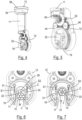
- Figs. 1 to 4 depict an auxiliary tool 10 for fixing a free end F of an adhesive tape 17 ( Figs. 6 and 7 ) to a strand W, e.g. a wire harness, according to an embodiment of the present disclosure.
- the auxiliary tool 10 comprises a base plate 12 with a mouth 14 for receiving the wire harness W.
- the mouth 14 has the shape of a broad slit which extends to an outer edge of the base plate 12 along a longitudinal axis A3 ( Fig. 1 ) with a dead end of the slit having a semi-circular shape.
- a rotatable ring 16 is adapted to rotate about a centre C ( Fig. 6 ) of the mouth 14.
- the rotatable ring 16 which also comprises a mouth 15 having the shape of the mouth 14 of the base plate 12, is rotated around the centre C by means of a motor 11 ( Fig. 4 ) that rotates a beveled drive gear 40 that meshes with further gears 42, 44 and 46 to rotate the rotatable ring 16 that has a teethed outer circumference.
- a one-piece and spring-loaded receptacle 30 may be provided having an opening at its circumference for receiving the strand W.
- the opening of the receptacle 30 is aligned with the mouth 15 of the rotatable ring 16.
- the receptacle 30 can be linearly shifted along respective rods 31 and 33 mounted on the rotatable ring 16 adjacent two opposing sides of the mouth 15.
- the rods 31 and 33 are arranged in parallel to each other and the receptacle 30 is spring-loaded by means of two springs S1 and S2 surrounding the rods 31 and 33. Accordingly, if the auxiliary tool 10 is positioned over the wire harness W ( Fig. 6 ) and urged against the wire harness ( Fig. 7 ), the receptacle 30 will be pushed against the force of the springs S1 and S2 until the centre of the wire harness W is located at the centre C of the mouths 14 and 15.
- the receptacle 30 comprises a single and continuous pressing surface 32 having no gaps or slits.
- the pressing surface 32 is concavely curved and has a generally semi-circular cross-section. Accordingly, the pressing surface 32 extends generally 180° about its centre of curvature.
- Fig. 5 shows that the corners of the receptacle 30 are rounded such that the receptacle 30 will not damage the tape already wrapped around the harness W.
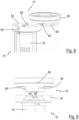
- the auxiliary tool 10 For mounting the auxiliary tool 10 to a manipulator, such as a robot 52 ( Fig. 1 ), the auxiliary tool 10 is provided at its upper end with a coupling 13 that may be generally disc-shaped and that is shown in more detail in Figs. 8 and 9 .
- the coupling of the disclosed embodiment is configured as a quick-mount coupling and comprises a male component 56 and a female component 54 that are generally disc-shaped and have a similar diameter.
- the female component 54 is fixed to the auxiliary tool 10 by means of screws or bolts and the male component 56 of the coupling 13 can be fixed to the robot 52 ( Fig. 1 ) or a rotatable fixture 50 by means of screws or bolts.
- the male component 56 comprises a protrusion 58 that is V-shaped in a top view and that has a dove-tailed cross-section (see Fig. 9 ).
- An outer circumferential wall 59 of the protrusion 58 is curved and the protrusion 58 can be slidably inserted into a complementary receiving grove 60 in the female component 54.
- a fixing screw (not shown) can be inserted into a radial bore 62 in the female component 54 and can be screwed into a thread 64 ( Fig. 8 ) in the protrusion 58 of the male component 56.
- the coupling 13 has a general outer contour of a disc (see Figs. 2 - 4 ).
- Fig. 1 depicts a system that comprises the auxiliary tool 10 mounted to the rotatable fixture 50 having an axis of rotation A1 by means of the coupling 13. Further, a taping head 60 is mounted to the rotatable fixture 50, wherein a longitudinal axis A2 of the taping head 60 and a longitudinal axis A3 of the auxiliary tool 10 may be oriented at the same angle with regard to the axis of rotation A1. As seen along the axis of rotation A1, the longitudinal axis A2 of the taping head 60 and the longitudinal axis A3 of the auxiliary tool 10 may be oriented at an angle of 120°.
- a coupling 13' that connects the taping head 60 with the rotatable fixture 50 may be similar or identical to the coupling 13 described above.
- the auxiliary tool 10 and the taping head 60 are mounted to the rotatable fixture 50 via the couplings 13 and 13', and the rotatable fixture 50 is configured to be rotated by the robot 52.
- the rotatable fixture 50 will be rotated e.g. about 120° around the axis A1. This has the effect that the mouths 14 and 15 of the auxiliary tool 10 will move to the previous position of the taping head 60.
- the robot 52 will then move the auxiliary tool 10 towards the harness W to place the mouths 14 and 15 over the harness W or in other words to introduce the harness W into the mouths 14 and 15 ( Fig. 6 ).
- the wire harness W wrapped with tape 17 but leaving a flag F will contact the receptacle 30.
- the movement of the auxiliary tool 10 is continued until the centres of the mouths 14 and 15 coincide with the centre of the wire harness ( Fig. 7 ).
- the motor 11 will be activated to rotate the gears 40 - 46 in order to rotate the rotatable ring 16 (in Fig. 7 in a clockwise direction).
- the flag F is pressed against the wire harness W by means of the rotating receptacle 30. Thereby, the flag is closed and the auxiliary tool 10 may be removed from the wire harness.
- an auxiliary tool 10 is compact and has a generally cylindrical shape.
- the elements of the auxiliary tool 10 are accommodated in the housing having an openable lid 19.
Landscapes
- Engineering & Computer Science (AREA)
- Mechanical Engineering (AREA)
- Manufacturing & Machinery (AREA)
- Basic Packing Technique (AREA)
Abstract
Description
- The present disclosure relates to an auxiliary tool for fixing a free end of an adhesive tape wrapped around a strand.
- Taping heads for taping a strand or a wire harness with a protective and/or adhesive tape are generally known. Such taping heads are used to manually or automatically wrap a tape around a bundle of wires. In industrial applications there is a need to automatically apply the tape to different wire harnesses or to different sections of a wire harness which requires that a tape which is supplied from a tape roll is cut and positioned.
- When applying a tape to a strand, the process is initialized by adhering the free end of the tape on the strand, wrapping the tape around the branch and cutting the tape at a desired length. Thereafter, due to the cutting process a free end of the adhesive tape may not adhere to the strand. This (loose) free end is also called a flag.
- A flag that is not closed (fixed on the strand) will require manual work and could result in quality issues.
- Accordingly, there is a need to provide an auxiliary tool for fixing a free end of an adhesive tape that has been wrapped around a strand.
- The present disclosure provides an auxiliary tool for fixing a free end of an adhesive tape that has been wrapped around a strand, wherein the tool comprises a base plate with a mouth for receiving the wrapped strand and a rotatable ring with a mouth adapted to rotate about an axis extending through the centre of the mouths. Further, a spring-loaded receptacle is provided for accommodating the strand wherein the receptacle is mounted to the rotatable ring. An opening of the receptacle can be aligned with the mouths for receiving the strand. If the ring is rotated, the receptacle is rotated about the strand by virtue of the ring being rotated. The auxiliary tool further has a coupling for connecting the auxiliary tool to a rotatable fixture or a manipulator such as a robot arm.
- With the above auxiliary tool, the flag of an adhesive tape wrapped around a strand can be closed by rotating the receptacle around the strand such that also the free end of the tape adheres to the strand thereby closing the flag. The coupling allows for a connection of the auxiliary tool to a robot. Therefore, the auxiliary tool can be manipulated automatically after a taping head has completed the wrapping process and has been removed. Since the present disclosure provides a distinct tool for fixing the flag of an adhesive tape, it is not necessary to re-design automatic taping heads to provide the desired functionality which would raise the complexity and the overall volume of such taping head.
- When positioning the auxiliary tool on a strand, the mouths of the rotatable ring and the base plate can be placed over the strand and the tool can be further fed against the strand without significantly deforming it. This allows for a good positioning of the strand in the centre of the mouths and in the receptacle. When the auxiliary tool is further urged against the strand, the receptacle will move against a spring force. Thereby, a central axis of the strand can be aligned with the centre of the mouths. Thereafter, the rotatable ring can be rotated and the receptacle will be rotated around the strand thereby closing the flag.
- According to an embodiment, the auxiliary tool may not comprise a tape roll, a cutting device or a tape roll holder. This means that such an auxiliary tool is exclusively dedicated for closing a flag and not for wrapping a tape around a strand.
- According to a further embodiment, the receptacle may comprise a single continuous pressing surface. Such surface without any intermediate gaps or slits results in a smooth pressing of the flag against the strand when the rotatable ring is rotated.
- According to a further embodiment, the pressing surface may be concavely curved and extend at least 90°, at least 120° or at least 180° about a centre of curvature. The receptacle may have a generally semi-circular cross-section. Thereby, a strand is well received in the receptacle and a flag can be smoothly applied to the strand.
- According to a further embodiment the receptacle is shiftably mounted on two parallel guide rods to achieve a smooth and linear movement of the receptacle when the auxiliary tool is pressed against the strand.
- According to a further embodiment, the coupling of the auxiliary tool is configured as a simple adapter plate that can be mounted to a robot arm. According to a further embodiment, the coupling is configured as a quick mount coupling that allows a quick release of the auxiliary tool from the robot arm for maintenance or replacement.
- According to a further embodiment the coupling may comprise a male and a female component and a locking element for interlocking the components, such as a screw, a bolt or the like.
- According to a further embodiment, the coupling may comprise a first component that is shiftably inserted into a second component. In this embodiment both components may be interlocked by means of a form-lock. To fix or release the tool at or from the robot arm it is then merely necessary to apply or remove a locking element that interconnects both components.
- According to a further embodiment, the first component may have a protrusion that is V-shaped in a top view and that has a dove-tailed cross-section. Such design provides a form-lock and a firm connection between the first and the second component. By means of the V-shape of the protrusion an alignment of both components is achieved when the protrusion is completely inserted in a complementary counterpart.
- According to a further embodiment, the protrusion may have a curved circumferential wall. This is advantageous if the coupling has the general shape of a disc.
- According to a further aspect of the present disclosure, a system is provided that comprises an auxiliary tool as disclosed above and a taping head, both mounted to a rotatable fixture that has an axis of rotation, wherein a longitudinal axis of the taping head and a longitudinal axis of the auxiliary tool are oriented at the same angle with regard to the axis of rotation. When such system is mounted to a robot arm, the taping head on the one hand and the auxiliary tool on the other hand can be brought in an operating position by merely turning the rotatable fixture. Thereby, a very fast change of the tools can be provided.
- According to a further embodiment, the longitudinal axis of the taping head and the longitudinal axis of the auxiliary tool are oriented at an angle of 120° as seen along the axis of rotation of the rotatable fixture. This serves to reduce the time required for changing the fools.
- Exemplary embodiments and functions of the present disclosure are described herein in conjunction with the following drawings, showing schematically:
- Fig. 1
- a side view of a system comprising an auxiliary tool and a taping head mounted to a rotatable fixture, according to an embodiment of the present disclosure;
- Fig. 2 and Fig. 3
- perspective views of an auxiliary tool according to an embodiment of the present disclosure;
- Fig. 4
- the perspective view of
Fig. 2 with a housing of the auxiliary tool being opened; - Fig. 5
- an enlarged illustration of
Fig. 4 ; - Fig. 6
- a plan view of
Fig. 5 ; - Fig. 7
- the illustration of
Fig. 6 with a strand being received in the receptacle; - Fig. 8
- a perspective view of two components of a coupling; and
- Fig. 9
- a side view of
Fig. 8 . -
Figs. 1 to 4 depict anauxiliary tool 10 for fixing a free end F of an adhesive tape 17 (Figs. 6 and 7 ) to a strand W, e.g. a wire harness, according to an embodiment of the present disclosure. Theauxiliary tool 10 comprises abase plate 12 with amouth 14 for receiving the wire harness W. Themouth 14 has the shape of a broad slit which extends to an outer edge of thebase plate 12 along a longitudinal axis A3 (Fig. 1 ) with a dead end of the slit having a semi-circular shape. Arotatable ring 16 is adapted to rotate about a centre C (Fig. 6 ) of themouth 14. Therotatable ring 16, which also comprises amouth 15 having the shape of themouth 14 of thebase plate 12, is rotated around the centre C by means of a motor 11 (Fig. 4 ) that rotates abeveled drive gear 40 that meshes withfurther gears rotatable ring 16 that has a teethed outer circumference. - For supporting and accommodating the wrapped wire harness W in the
mouths receptacle 30 may be provided having an opening at its circumference for receiving the strand W. The opening of thereceptacle 30 is aligned with themouth 15 of therotatable ring 16. Thereceptacle 30 can be linearly shifted alongrespective rods rotatable ring 16 adjacent two opposing sides of themouth 15. Therods receptacle 30 is spring-loaded by means of two springs S1 and S2 surrounding therods auxiliary tool 10 is positioned over the wire harness W (Fig. 6 ) and urged against the wire harness (Fig. 7 ), thereceptacle 30 will be pushed against the force of the springs S1 and S2 until the centre of the wire harness W is located at the centre C of themouths - As shown in the drawings, the
receptacle 30 comprises a single and continuouspressing surface 32 having no gaps or slits. In the disclosed embodiment thepressing surface 32 is concavely curved and has a generally semi-circular cross-section. Accordingly, thepressing surface 32 extends generally 180° about its centre of curvature.Fig. 5 shows that the corners of thereceptacle 30 are rounded such that thereceptacle 30 will not damage the tape already wrapped around the harness W. - For mounting the
auxiliary tool 10 to a manipulator, such as a robot 52 (Fig. 1 ), theauxiliary tool 10 is provided at its upper end with acoupling 13 that may be generally disc-shaped and that is shown in more detail inFigs. 8 and 9 . The coupling of the disclosed embodiment is configured as a quick-mount coupling and comprises amale component 56 and afemale component 54 that are generally disc-shaped and have a similar diameter. Thefemale component 54 is fixed to theauxiliary tool 10 by means of screws or bolts and themale component 56 of thecoupling 13 can be fixed to the robot 52 (Fig. 1 ) or arotatable fixture 50 by means of screws or bolts. - For connecting both
components male component 56 comprises aprotrusion 58 that is V-shaped in a top view and that has a dove-tailed cross-section (seeFig. 9 ). An outercircumferential wall 59 of theprotrusion 58 is curved and theprotrusion 58 can be slidably inserted into a complementary receivinggrove 60 in thefemale component 54. - When the
protrusion 58 of themale component 56 is completely inserted into thegrove 60 of thefemale component 54, a fixing screw (not shown) can be inserted into a radial bore 62 in thefemale component 54 and can be screwed into a thread 64 (Fig. 8 ) in theprotrusion 58 of themale component 56. When bothcomponents coupling 13 has a general outer contour of a disc (seeFigs. 2 - 4 ). -
Fig. 1 depicts a system that comprises theauxiliary tool 10 mounted to therotatable fixture 50 having an axis of rotation A1 by means of thecoupling 13. Further, a tapinghead 60 is mounted to therotatable fixture 50, wherein a longitudinal axis A2 of the tapinghead 60 and a longitudinal axis A3 of theauxiliary tool 10 may be oriented at the same angle with regard to the axis of rotation A1. As seen along the axis of rotation A1, the longitudinal axis A2 of the tapinghead 60 and the longitudinal axis A3 of theauxiliary tool 10 may be oriented at an angle of 120°. Advantageously, a coupling 13' that connects the tapinghead 60 with therotatable fixture 50 may be similar or identical to thecoupling 13 described above. In the embodiment ofFig. 1 , theauxiliary tool 10 and the tapinghead 60 are mounted to therotatable fixture 50 via thecouplings 13 and 13', and therotatable fixture 50 is configured to be rotated by therobot 52. - After an
adhesive tape 17 has been wrapped around the harness W by means of the tapinghead 60, therotatable fixture 50 will be rotated e.g. about 120° around the axis A1. This has the effect that themouths auxiliary tool 10 will move to the previous position of the tapinghead 60. Therobot 52 will then move theauxiliary tool 10 towards the harness W to place themouths mouths 14 and 15 (Fig. 6 ). At a certain point in time the wire harness W wrapped withtape 17 but leaving a flag F will contact thereceptacle 30. The movement of theauxiliary tool 10 is continued until the centres of themouths Fig. 7 ). - Thereafter, the
motor 11 will be activated to rotate the gears 40 - 46 in order to rotate the rotatable ring 16 (inFig. 7 in a clockwise direction). As a result, the flag F is pressed against the wire harness W by means of therotating receptacle 30. Thereby, the flag is closed and theauxiliary tool 10 may be removed from the wire harness. - As shown in the drawings, the disclosed embodiment of an
auxiliary tool 10 is compact and has a generally cylindrical shape. The elements of theauxiliary tool 10 are accommodated in the housing having anopenable lid 19.
Claims (14)
- Auxiliary tool (10) for fixing a free end of an adhesive tape wrapped around a strand (W), said tool (10) comprising- a base plate (12) with a mouth (14) for receiving the wrapped strand,- a rotatable ring (16) with a mouth (15) adapted to rotate about an axis extending through the centre (C) of the mouths (14, 15), and- a spring-loaded receptacle (30) for accommodating the strand (W), wherein the receptacle (30) is mounted to the rotatable ring (16), and- a coupling (13) for connecting the tool (10) to a rotatable fixture (50).
- Auxiliary tool according to claim 1, having no tape roll and no cutting device.
- Auxiliary tool any one of the preceding claims, wherein the receptacle (30) comprises a single continuous pressing surface (32).
- Auxiliary tool according to claim 3, wherein the pressing surface (32) is concavely curved and extends at least 90°, at least 120° or at least 180° about a centre of curvature.
- Auxiliary tool according to any one of the preceding claims, wherein the receptacle (32) has a generally semi-circular cross-section.
- Auxiliary tool according to any one of the preceding claims, wherein the receptacle (32) is shiftably mounted on two parallel guide rods (31, 33).
- Auxiliary tool according to any one of the preceding claims, wherein the coupling (13) is configured as a quick mount coupling.
- Auxiliary tool according to any one of the preceding claims, wherein the coupling (13) comprises a male component (56) and a female component (54) and a locking element for interlocking the components.
- Auxiliary tool according to any one of the preceding claims, wherein the coupling (13) comprises a first component (56) that is shiftably inserted into a second component (54).
- Auxiliary tool according to the preceding claim, wherein the first component (56) has a protrusion (58) that is V-shaped in a top view and that has a dove-tailed cross-section.
- Auxiliary tool according to the preceding claim, wherein the protrusion (58) has a curved circumferential wall (59).
- A system comprising the auxiliary tool (10) according to any one of the preceding claims and a taping head (60), both mounted to a rotatable fixture (50) having an axis of rotation (A1), wherein a longitudinal axis (A2) of the taping head (60) and a longitudinal axis (A3) of the auxiliary tool (10) are oriented at the same angle with regard to the axis of rotation (A1).
- A system according to the preceding claim, wherein as seen along the axis of rotation (A1) the longitudinal axis (A2) of the taping head (60) and the longitudinal axis (A3) of the auxiliary tool (10) are oriented at an angle of 120°.
- A system according to claim 12 or 13, wherein the taping head (60) and/or the auxiliary tool (10) is/are provided with a coupling that is configured as a quick mount coupling.
Priority Applications (4)
| Application Number | Priority Date | Filing Date | Title |
|---|---|---|---|
| EP22176675.1A EP4287219B1 (en) | 2022-06-01 | 2022-06-01 | Automatic flag closing tool |
| EP26164993.3A EP4734131A2 (en) | 2022-06-01 | 2022-06-01 | Automatic flag closing tool |
| US18/144,402 US12319009B2 (en) | 2022-06-01 | 2023-05-08 | Auxiliary tool |
| CN202310644421.7A CN117142227B (en) | 2022-06-01 | 2023-06-01 | auxiliary tools |
Applications Claiming Priority (1)
| Application Number | Priority Date | Filing Date | Title |
|---|---|---|---|
| EP22176675.1A EP4287219B1 (en) | 2022-06-01 | 2022-06-01 | Automatic flag closing tool |
Related Child Applications (2)
| Application Number | Title | Priority Date | Filing Date |
|---|---|---|---|
| EP26164993.3A Division EP4734131A2 (en) | 2022-06-01 | 2022-06-01 | Automatic flag closing tool |
| EP26164993.3A Division-Into EP4734131A2 (en) | 2022-06-01 | 2022-06-01 | Automatic flag closing tool |
Publications (2)
| Publication Number | Publication Date |
|---|---|
| EP4287219A1 true EP4287219A1 (en) | 2023-12-06 |
| EP4287219B1 EP4287219B1 (en) | 2026-04-22 |
Family
ID=82258318
Family Applications (2)
| Application Number | Title | Priority Date | Filing Date |
|---|---|---|---|
| EP22176675.1A Active EP4287219B1 (en) | 2022-06-01 | 2022-06-01 | Automatic flag closing tool |
| EP26164993.3A Pending EP4734131A2 (en) | 2022-06-01 | 2022-06-01 | Automatic flag closing tool |
Family Applications After (1)
| Application Number | Title | Priority Date | Filing Date |
|---|---|---|---|
| EP26164993.3A Pending EP4734131A2 (en) | 2022-06-01 | 2022-06-01 | Automatic flag closing tool |
Country Status (3)
| Country | Link |
|---|---|
| US (1) | US12319009B2 (en) |
| EP (2) | EP4287219B1 (en) |
| CN (1) | CN117142227B (en) |
Citations (3)
| Publication number | Priority date | Publication date | Assignee | Title |
|---|---|---|---|---|
| US20130019565A1 (en) * | 2011-07-19 | 2013-01-24 | Adam Witkiewicz | Wrapper assembly |
| EP3716295A1 (en) * | 2019-03-25 | 2020-09-30 | The Boeing Company | An adaptive bundle gripping end effector |
| US20220123534A1 (en) * | 2019-02-27 | 2022-04-21 | Daewon Electric Co.,Ltd. | Automatic opening and closing stripping device for indirect live wire having wire stripping and taping functions, and methods for stripping and taping indirect live wire using same |
Family Cites Families (6)
| Publication number | Priority date | Publication date | Assignee | Title |
|---|---|---|---|---|
| DE202008004087U1 (en) * | 2008-03-22 | 2008-05-21 | Gack, Josef | Device for setting and insulating electrical conductors and / or bundles of electrical conductors |
| DE202016002622U1 (en) * | 2016-04-22 | 2016-05-30 | Kabatec GmbH & Co. KG | Device for wrapping an elongate bundle material with an adhesive tape |
| US11052930B2 (en) * | 2017-06-16 | 2021-07-06 | Verb Surgical Inc. | Robotic arm cart having locking swivel joints and other position adjustment features and uses therefor |
| US12071761B2 (en) | 2017-11-21 | 2024-08-27 | Nitto Denko Corporation | Sound reducing system |
| DE102017130895B4 (en) * | 2017-12-21 | 2023-06-29 | Lisa Dräxlmaier GmbH | Winding device and method for fully automated wrapping of a bundle of wires with an adhesive tape |
| DE102020123771A1 (en) * | 2020-09-11 | 2022-03-17 | Kabatec GmbH & Co. KG | Winding device for wrapping an elongate bundle and method for wrapping a bundle with an adhesive tape |
-
2022
- 2022-06-01 EP EP22176675.1A patent/EP4287219B1/en active Active
- 2022-06-01 EP EP26164993.3A patent/EP4734131A2/en active Pending
-
2023
- 2023-05-08 US US18/144,402 patent/US12319009B2/en active Active
- 2023-06-01 CN CN202310644421.7A patent/CN117142227B/en active Active
Patent Citations (3)
| Publication number | Priority date | Publication date | Assignee | Title |
|---|---|---|---|---|
| US20130019565A1 (en) * | 2011-07-19 | 2013-01-24 | Adam Witkiewicz | Wrapper assembly |
| US20220123534A1 (en) * | 2019-02-27 | 2022-04-21 | Daewon Electric Co.,Ltd. | Automatic opening and closing stripping device for indirect live wire having wire stripping and taping functions, and methods for stripping and taping indirect live wire using same |
| EP3716295A1 (en) * | 2019-03-25 | 2020-09-30 | The Boeing Company | An adaptive bundle gripping end effector |
Also Published As
| Publication number | Publication date |
|---|---|
| US20230391019A1 (en) | 2023-12-07 |
| EP4734131A2 (en) | 2026-04-29 |
| EP4287219B1 (en) | 2026-04-22 |
| CN117142227B (en) | 2026-02-06 |
| US12319009B2 (en) | 2025-06-03 |
| CN117142227A (en) | 2023-12-01 |
Similar Documents
| Publication | Publication Date | Title |
|---|---|---|
| KR102020921B1 (en) | Insulation coating stripping device for wire | |
| US4869135A (en) | Apparatus for step stripping wire means | |
| CN111740340B (en) | Adaptive beam clamping end effector | |
| EP3841856B1 (en) | Wiring robot and method of wiring | |
| US11187350B2 (en) | Subsea flange tool | |
| EP2176928B1 (en) | Tool for powered pressing of cable connectors | |
| EP4287219B1 (en) | Automatic flag closing tool | |
| WO2015055753A1 (en) | Assembly station and also method for fitting clips to a line bundle in an automated manner, and clip delivery unit | |
| US20230126924A1 (en) | Valve insertion tool | |
| EP3037190A1 (en) | Gripping device for mechanical fasteners | |
| CN100474012C (en) | Device for installing an optical fibre in a splice connector | |
| US11407131B2 (en) | Low profile universal cable tie cutting tool for wire damage prevention | |
| DE10006226A1 (en) | Tool adapter on a robot interface | |
| US20040181947A1 (en) | Cutting Device for Workpieces Such as Rods, Bolts and the Like, Especially for Threaded Rods | |
| KR20210083130A (en) | Indirect automatic taping device for insulated wire | |
| US20100115775A1 (en) | Extension cable and pipe processing device adapted thereto | |
| JPH0270213A (en) | Device for peeling off shield of cable | |
| US20040187645A1 (en) | Tool for securing clamp to object | |
| JP7105122B2 (en) | Wire coating stripping device | |
| TWI915448B (en) | Wire holding device and method for separating live wires | |
| CN209929873U (en) | Foil layer stripping device | |
| FR2537908A1 (en) | Gripping device, particularly for industrial robot | |
| US5628178A (en) | Sprocket chain master link | |
| JPH03270615A (en) | Wire peeler | |
| WO2018110227A1 (en) | Tape winding device |
Legal Events
| Date | Code | Title | Description |
|---|---|---|---|
| PUAI | Public reference made under article 153(3) epc to a published international application that has entered the european phase |
Free format text: ORIGINAL CODE: 0009012 |
|
| STAA | Information on the status of an ep patent application or granted ep patent |
Free format text: STATUS: THE APPLICATION HAS BEEN PUBLISHED |
|
| AK | Designated contracting states |
Kind code of ref document: A1 Designated state(s): AL AT BE BG CH CY CZ DE DK EE ES FI FR GB GR HR HU IE IS IT LI LT LU LV MC MK MT NL NO PL PT RO RS SE SI SK SM TR |
|
| RAP1 | Party data changed (applicant data changed or rights of an application transferred) |
Owner name: APTIV TECHNOLOGIES AG |
|
| STAA | Information on the status of an ep patent application or granted ep patent |
Free format text: STATUS: REQUEST FOR EXAMINATION WAS MADE |
|
| 17P | Request for examination filed |
Effective date: 20240513 |
|
| RBV | Designated contracting states (corrected) |
Designated state(s): AL AT BE BG CH CY CZ DE DK EE ES FI FR GB GR HR HU IE IS IT LI LT LU LV MC MK MT NL NO PL PT RO RS SE SI SK SM TR |
|
| RAP3 | Party data changed (applicant data changed or rights of an application transferred) |
Owner name: APTIV TECHNOLOGIES AG |
|
| GRAP | Despatch of communication of intention to grant a patent |
Free format text: ORIGINAL CODE: EPIDOSNIGR1 |
|
| STAA | Information on the status of an ep patent application or granted ep patent |
Free format text: STATUS: GRANT OF PATENT IS INTENDED |
|
| INTG | Intention to grant announced |
Effective date: 20251120 |
|
| GRAS | Grant fee paid |
Free format text: ORIGINAL CODE: EPIDOSNIGR3 |
|
| GRAA | (expected) grant |
Free format text: ORIGINAL CODE: 0009210 |
|
| STAA | Information on the status of an ep patent application or granted ep patent |
Free format text: STATUS: THE PATENT HAS BEEN GRANTED |
|
| P01 | Opt-out of the competence of the unified patent court (upc) registered |
Free format text: CASE NUMBER: UPC_APP_0008716_4287219/2026 Effective date: 20260304 |
|
| AK | Designated contracting states |
Kind code of ref document: B1 Designated state(s): AL AT BE BG CH CY CZ DE DK EE ES FI FR GB GR HR HU IE IS IT LI LT LU LV MC MK MT NL NO PL PT RO RS SE SI SK SM TR |
|
| REG | Reference to a national code |
Ref country code: CH Ref legal event code: F10 Free format text: ST27 STATUS EVENT CODE: U-0-0-F10-F00 (AS PROVIDED BY THE NATIONAL OFFICE) Effective date: 20260422 Ref country code: GB Ref legal event code: FG4D |