EP4287169A1 - Wristband - Google Patents
Wristband Download PDFInfo
- Publication number
- EP4287169A1 EP4287169A1 EP21923256.8A EP21923256A EP4287169A1 EP 4287169 A1 EP4287169 A1 EP 4287169A1 EP 21923256 A EP21923256 A EP 21923256A EP 4287169 A1 EP4287169 A1 EP 4287169A1
- Authority
- EP
- European Patent Office
- Prior art keywords
- wristband
- slit
- breaking
- slits
- band portion
- Prior art date
- Legal status (The legal status is an assumption and is not a legal conclusion. Google has not performed a legal analysis and makes no representation as to the accuracy of the status listed.)
- Pending
Links
Images



Classifications
-
- G—PHYSICS
- G09—EDUCATION; CRYPTOGRAPHY; DISPLAY; ADVERTISING; SEALS
- G09F—DISPLAYING; ADVERTISING; SIGNS; LABELS OR NAME-PLATES; SEALS
- G09F3/00—Labels, tag tickets, or similar identification or indication means; Seals; Postage or like stamps
- G09F3/005—Identification bracelets, e.g. secured to the arm of a person
-
- G—PHYSICS
- G09—EDUCATION; CRYPTOGRAPHY; DISPLAY; ADVERTISING; SEALS
- G09F—DISPLAYING; ADVERTISING; SIGNS; LABELS OR NAME-PLATES; SEALS
- G09F3/00—Labels, tag tickets, or similar identification or indication means; Seals; Postage or like stamps
- G09F3/02—Forms or constructions
- G09F3/03—Forms or constructions of security seals
- G09F3/0305—Forms or constructions of security seals characterised by the type of seal used
- G09F3/0341—Forms or constructions of security seals characterised by the type of seal used having label sealing means
-
- A—HUMAN NECESSITIES
- A44—HABERDASHERY; JEWELLERY
- A44C—PERSONAL ADORNMENTS, e.g. JEWELLERY; COINS
- A44C5/00—Bracelets; Wrist-watch straps; Fastenings for bracelets or wrist-watch straps
- A44C5/0007—Bracelets specially adapted for other functions or with means for attaching other articles
- A44C5/0015—Bracelets specially adapted for other functions or with means for attaching other articles providing information, e.g. bracelets with calendars
-
- G—PHYSICS
- G09—EDUCATION; CRYPTOGRAPHY; DISPLAY; ADVERTISING; SEALS
- G09F—DISPLAYING; ADVERTISING; SIGNS; LABELS OR NAME-PLATES; SEALS
- G09F3/00—Labels, tag tickets, or similar identification or indication means; Seals; Postage or like stamps
- G09F3/02—Forms or constructions
- G09F2003/0225—Carrier web
- G09F2003/0227—Carrier strip
-
- G—PHYSICS
- G09—EDUCATION; CRYPTOGRAPHY; DISPLAY; ADVERTISING; SEALS
- G09F—DISPLAYING; ADVERTISING; SIGNS; LABELS OR NAME-PLATES; SEALS
- G09F3/00—Labels, tag tickets, or similar identification or indication means; Seals; Postage or like stamps
- G09F3/02—Forms or constructions
- G09F2003/0264—Shapes or borders
- G09F2003/0267—Shapes or borders die cut
-
- G—PHYSICS
- G09—EDUCATION; CRYPTOGRAPHY; DISPLAY; ADVERTISING; SEALS
- G09F—DISPLAYING; ADVERTISING; SIGNS; LABELS OR NAME-PLATES; SEALS
- G09F3/00—Labels, tag tickets, or similar identification or indication means; Seals; Postage or like stamps
- G09F3/02—Forms or constructions
- G09F2003/0276—Safety features, e.g. colour, prominent part, logo
- G09F2003/0277—Tamper resistant
Definitions
- the present invention relates to a wristband.
- JP 2020-38386 A discloses a wristband used for identifying a patient or an examinee in a medical institution or the like.
- a breaking slit is formed such that a band portion is broken when an attached portion is about to be peeled off in order to prevent unauthorized use between users.
- an object of the present invention is to provide a wristband that is formed in a ring shape by attaching an end, which is an attached portion, of the wristband to a part of a band portion. When the end is peeled off from the band portion, the end is reliably broken and cannot be used again as the wristband.
- a wristband including a belt-shaped band portion and an adhesive portion formed by laminating an adhesive on one end of the band portion, the wristband being formed in a ring shape by attaching the adhesive portion to a part of the band portion.
- a plurality of first breaking slits are formed in a radial shape at the end, and each of the first breaking slits includes two parallel first line segments and a second line segment that connects one end of each of the first line segments and is longer than each of the first line segments, and is formed such that an opening formed by the first line segments and the second line segment is directed toward a radial center.
- the first breaking slits are formed in a radial shape at the end of the belt-shaped band portion, each of the first breaking slits including two parallel first line segments and a second line segment that connects one end of each of the first line segments and is longer than each of the first line segments, and being formed such that an opening formed by the first line segments and the second line segment is directed toward a radial center. Therefore, when the end is peeled off from the band portion from the outer edge side toward the inner side of the end, the end cleaves along the second line segment of the first breaking slit, the tear spreads along a pair of first line segments, and the end is broken first from end portions of the first line segments.
- the first breaking slits are formed in a radial shape, and thus the end cannot maintain a state before being attached and cannot be formed in a ring shape again when the end of the wristband is about to be peeled off from the band portion.
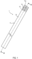
- FIG. 1 is a plan view of a wristband 1 according to an embodiment of the present invention as viewed from a front surface side.
- FIG. 2 is a plan view of the wristband 1 as viewed from a back surface side.
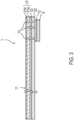
- FIG. 3 is a cross-sectional view taken along a line III-III of FIG. 1 .
- a front surface of the wristband 1 is a surface on which predetermined designs and characters are printed in advance.
- a back surface of the wristband 1 is a surface opposite to the front surface and in contact with human skin.
- the wristband 1 includes a belt-shaped band portion 11 and an adhesive portion 12 formed on the back surface of one end 11a of the band portion 11.
- a thermal substrate 21 and a back surface substrate 22 are laminated on a laminate layer 23.
- a separator S is temporarily attached to the adhesive portion 12 formed on the back surface of the end 11a.
- the separator S is not shown in FIG. 1 .
- the thermal substrate 21 is provided with a thermosensitive coloring layer 21b on a surface substrate 21a. Therefore, the thermal substrate 21 on which the thermosensitive coloring layer 21b is arranged constitutes the front surface of the wristband 1.
- a single resin film such as polyvinyl chloride, polyethylene terephthalate, polypropylene, polyethylene, or polyethylene naphthalate, or a multilayer film obtained by laminating a plurality of these resin films may be used.
- a paper substrate such as cardboard, high-quality paper, medium-quality paper, or coated paper obtained by appropriately forming a coating layer on the paper can be used.
- a thickness of the surface substrate 21a may be 10 pm or more and 300 pm or less.
- the paper having a thickness of 50 pm or more and 260 pm or less can be used, and the thickness is preferably 80 pm in general.
- thermosensitive coloring layer 21b is made of a material that develops color by thermal scanning of a thermal head of a printer (not shown).
- the back surface substrate 22 constitutes the back surface of the wristband 1.
- the back surface substrate 22 is embossed. Accordingly, it is possible to ensure air permeability between the wristband and the human skin.
- the embossing imparts a cushioning property to the back surface substrate 22 and makes the wristband soft to touch the skin.
- the laminate layer 23 is a polyethylene resin.
- the thermal substrate 21 and the back surface substrate 22 are heat-sealed with a molten polyethylene resin.
- any material that is generally used as an adhesive for lamination can be appropriately used.
- an adhesive or a bonding agent of acrylic system, urethane system, silicone system, rubber system, or the like can be used.
- Examples of an adhesive for forming the adhesive portion 12 include an adhesive or a bonding agent of acrylic system, urethane system, silicone system, rubber system, or the like.
- a breaking slit 13 is formed at the end 11a of the band portion 11 at which the adhesive portion 12 is formed.
- the breaking slit 13 is a slit that penetrates the band portion 11, and is formed at a position of the adhesive portion 12 arranged at the end 11a.
- FIG. 4 is a perspective view of the wristband 1 according to the embodiment.
- the wristband 1 is used in a ring shape by being wound around a wrist and attaching the adhesive portion 12 formed on the back surface of the end 11a to a part of the front surface of the band portion 11. Since the adhesive portion 12 can be attached to any position on the front surface of the band portion 11, a ring diameter is adjustable.
- An arrow P shown in FIG. 4 is for explaining a direction in which the end 11a is peeled off.
- a direction of the arrow P shown in FIG. 4 corresponds to a direction of an arrow P shown in FIG. 6 to be described later.
- FIG. 5 shows one slit element 30 of the breaking slit 13.
- the slit element 30 is formed by connecting two parallel first line segments 31 and 32 and a second line segment 33.
- the second line segment 33 connects one end 31a and one end 32a of the first line segments 31 and 32, and the second line segment 33 is longer than the first line segments 31 and 32.
- ends 31b and 32b opposite to the ends 31a and 32a connected by the second line segment 33 are bent toward an inside of an opening 34 to form bent portions 35 and 36.
- connecting portions between the bent portions 35 and 36 and the first line segments 31 and 32 and the second line segment 33 are formed by curved lines. Therefore, tear of the slit element 30 is likely to expand for the peeling of the end 11a.
- the slit element 30 has a shape of an alphabet "C" of an Agency-FB font.
- a plurality of the slit elements 30 are formed in a radial shape at the end 11a.
- the slit element 30 is formed such that the opening 34 formed by the first line segments 31 and 32 and the second line segment 33 is directed toward a radial center.
- FIG. 6 shows a plurality of breaking slits 13 formed at the end 11a.
- the breaking slit 13 includes a plurality of first breaking slits 131 (hereinafter referred to as first slits 131), a plurality of second breaking slits 133 (hereinafter referred to as second slits 133), and a plurality of third breaking slits 135 (hereinafter referred to as third slits 135).
- first slits 131 a plurality of first breaking slits 131
- second slits 133 hereinafter referred to as second slits 133
- third breaking slits 135 hereinafter referred to as third slits 135.
- the first slits 131, the second slits 133, and the third slits 135 correspond to the slit elements 30.
- first slits 131a, 131b, 131c, and 131d there are first slits 131a, 131b, 131c, and 131d. Further, there are second slits 133a, 133b, 133c, and 133d. Further, there are third slits 135a, 135b, 135c, and 135d.
- the first slits 131a to 131d are referred to as the first slits 131 without using alphabetic branch numbers. The same applies to the following description of a configuration including the second slit to be described later.
- the first slits 131a, 131b, 131c, and 131d are arranged radially, respectively.
- the adjacent first slits 131 are formed discontinuously to each other.
- the second slits 133 each being discontinuous with a corresponding one of the first slits 131 and each having the same shape as the first slit 131 are formed outside the first slit 131 in a radial direction.
- the second slit 133a is formed outside the first slit 131a in the radial direction.
- the second slit 133b is formed outside the first slit 131b in the radial direction.
- the second slit 133c is formed outside the first slit 131c in the radial direction.
- the second slit 133d is formed outside the first slit 131d in the radial direction.
- the third slits 135 each being discontinuous with a corresponding one of the first slits 131 and a corresponding one of the second slits 133 are formed outside discontinuous portions 132 between adjacent ones of the first slits 131 in the radial direction.
- the third slit 135a is formed outside a discontinuous portion 132a in the radial direction.
- the third slit 135b is formed outside a discontinuous portion 132b in the radial direction.
- the third slit 135c is formed outside a discontinuous portion 132c in the radial direction.
- the third slit 135d is formed outside a discontinuous portion 132d in the radial direction.
- a central slit 136 is formed at the radial center of the breaking slit 13.
- An opening direction of the central slit 136 is any direction.
- the opening direction of the central slit 136 may be the same as an opening direction of any of the first slit 131, the second slit 133, and the third slit 135, or may not coincide with the opening direction of any of the slits.
- the wristband 1 has a ring shape in a state in which the breaking slit 13 is formed at the end 11a, and has a mechanism in which the breaking slit 13 cleaves and the end 11a breaks when the end 11a attached to a part of the front surface of the band portion 11 is peeled off from the band portion 11.
- the second slit 133a cleaves along the radial direction, and a periphery of a region A defined by the second slit 133a is peeled off while the region A remains on the front surface of the band portion 11.
- the bent portions 35 and 36 are formed in the first slit 131 and the second slit 133 (slit elements 30). Therefore, since a width of a portion remaining on the front surface of the band portion 11 is narrowed, the wristband is likely to break at the bent portions 35 and 36.
- the tear expands along the first slit 131a, and thus a periphery of a region B defined by the first slit 131a is peeled off while the region B remains on the front surface of the band portion 11. Accordingly, the breakage of the end 11a in the discontinuous portion expands.
- the wristband 1 As described above, in the wristband 1 according to the embodiment, at this time, the history of peeling off the end 11a of the band portion 11 formed in a ring shape becomes visually clear. After being peeled off, the end 11a is not in a state before being attached to the band portion 11, and thus the ring shape cannot be formed again. Therefore, the wristband 1 cannot be reused.
- the wristband 1 according to the embodiment can be suitably used instead of an admission ticket in an event site or a concert.
- FIG. 7 is a perspective view for explaining a continuous body of the wristband 1 according to the embodiment.
- the wristband 1 is provided in a form of a roll-shaped continuous body R as an example.
- tear-off perforation 40 is performed on a boundary between the wristband 1 and a wristband 2.
- the continuous body R is set in a printer (not shown), and printing is performed on the thermal substrate 21 of the band portion 11 while the continuous body R is fed out in a direction of an arrow F of FIG. 7 .
- the continuous body R is formed such that the breaking slit 13 is located on the rear side in the feeding direction F of the continuous body R, that is, upstream in a conveying direction.
- the continuous body R is fed out while sliding with a thermal head during printing.
- the first slit 131, the second slit 133, and the third slit 135 are formed to have curved portions, and thus when the thermal head slides and moves on the front surface of the band portion 11, the thermal head and the breaking slit 13 are hardly caught, and the periphery of the breaking slit 13 is not rolled up during printing.
- the four corners of the band portion 11 may be formed in an arc shape. This case can be realized by forming perforations for cutting out the four corners of the wristband 1 in an arc shape. Since the four corners of the wristband 1 are arc-shaped, it is possible to reduce stimulation when the wristband 1 touches the human skin.
- the wristband 1 may be compatible with RFID. That is, the wristband 1 may include an RFID inlay in which an IC chip with RFID specifications is connected to an antenna pattern.
- the RFID inlay may be laminated between the band substrate and the surface substrate of the wristband 1 or may be laminated outside the surface substrate.
- the wristband 1 in which the thermal substrate 21 and the back surface substrate 22 are laminated as the band portion 11 is described, but a substrate for heat transfer printing or a substrate for inkjet may be used instead of the thermal substrate 21.
- the band portion 11 may be a laminate of a plurality of substrates, or may be a single substrate.
- FIG. 8 is a plan view of a label 100 to which the breaking slit 13 according to the embodiment is applied.
- the breaking slit described in the embodiment and the modification can also be applied to a label that is used by being attached to an adherend.
Landscapes
- Engineering & Computer Science (AREA)
- Physics & Mathematics (AREA)
- General Physics & Mathematics (AREA)
- Theoretical Computer Science (AREA)
- Computer Security & Cryptography (AREA)
- Professional, Industrial, Or Sporting Protective Garments (AREA)
Abstract
Description
- The present invention relates to a wristband.
- A wristband is used instead of an admission ticket at an event site or a concert.
JP 2020-38386 A - In the wristband described in
JP 2020-38386 A - However, with the breaking slit of the related art, depending on a peeling direction, the attached portion can be peeled off without breaking, and there is room for improvement.
- Therefore, an object of the present invention is to provide a wristband that is formed in a ring shape by attaching an end, which is an attached portion, of the wristband to a part of a band portion. When the end is peeled off from the band portion, the end is reliably broken and cannot be used again as the wristband.
- According to an aspect of the present invention, there is provided a wristband including a belt-shaped band portion and an adhesive portion formed by laminating an adhesive on one end of the band portion, the wristband being formed in a ring shape by attaching the adhesive portion to a part of the band portion. A plurality of first breaking slits are formed in a radial shape at the end, and each of the first breaking slits includes two parallel first line segments and a second line segment that connects one end of each of the first line segments and is longer than each of the first line segments, and is formed such that an opening formed by the first line segments and the second line segment is directed toward a radial center.
- According to the above aspect of the present invention, the first breaking slits are formed in a radial shape at the end of the belt-shaped band portion, each of the first breaking slits including two parallel first line segments and a second line segment that connects one end of each of the first line segments and is longer than each of the first line segments, and being formed such that an opening formed by the first line segments and the second line segment is directed toward a radial center. Therefore, when the end is peeled off from the band portion from the outer edge side toward the inner side of the end, the end cleaves along the second line segment of the first breaking slit, the tear spreads along a pair of first line segments, and the end is broken first from end portions of the first line segments. The first breaking slits are formed in a radial shape, and thus the end cannot maintain a state before being attached and cannot be formed in a ring shape again when the end of the wristband is about to be peeled off from the band portion.
-
- [
FIG. 1] FIG. 1 is a plan view of a wristband according to an embodiment of the present invention as viewed from a front surface side. - [
FIG. 2] FIG. 2 is a plan view of the wristband according to the embodiment as viewed from a back surface side. - [
FIG. 3] FIG. 3 is a cross-sectional view taken along a line III-III ofFIG. 1 . - [
FIG. 4] FIG. 4 is a perspective view for explaining the wristband according to the embodiment. - [
FIG. 5] FIG. 5 shows a shape of a slit element of a breaking slit. - [
FIG. 6] FIG. 6 shows a plurality of breaking slits formed at an end. - [
FIG. 7] FIG. 7 is a perspective view for explaining a continuous body of the wristband according to the embodiment. - [
FIG. 8] FIG. 8 is a plan view of a label to which the breaking slit according to the embodiment is applied. -
FIG. 1 is a plan view of awristband 1 according to an embodiment of the present invention as viewed from a front surface side.FIG. 2 is a plan view of thewristband 1 as viewed from a back surface side.FIG. 3 is a cross-sectional view taken along a line III-III ofFIG. 1 . - In the embodiment, a front surface of the
wristband 1 is a surface on which predetermined designs and characters are printed in advance. A back surface of thewristband 1 is a surface opposite to the front surface and in contact with human skin. - The
wristband 1 includes a belt-shaped band portion 11 and anadhesive portion 12 formed on the back surface of oneend 11a of theband portion 11. - As shown in
FIG. 3 , in theband portion 11, athermal substrate 21 and aback surface substrate 22 are laminated on a laminate layer 23. A separator S is temporarily attached to theadhesive portion 12 formed on the back surface of theend 11a. For the sake of clarity of the drawings, the separator S is not shown inFIG. 1 . - As shown in
FIG. 3 , thethermal substrate 21 is provided with athermosensitive coloring layer 21b on asurface substrate 21a. Therefore, thethermal substrate 21 on which thethermosensitive coloring layer 21b is arranged constitutes the front surface of thewristband 1. - As a material applicable to the
surface substrate 21a, a single resin film such as polyvinyl chloride, polyethylene terephthalate, polypropylene, polyethylene, or polyethylene naphthalate, or a multilayer film obtained by laminating a plurality of these resin films may be used. - In addition to the resin film substrate, a paper substrate such as cardboard, high-quality paper, medium-quality paper, or coated paper obtained by appropriately forming a coating layer on the paper can be used.
- In the embodiment, a thickness of the
surface substrate 21a may be 10 pm or more and 300 pm or less. When paper is used as thesurface substrate 21a, in the above range, the paper having a thickness of 50 pm or more and 260 pm or less can be used, and the thickness is preferably 80 pm in general. - When a resin film is used as the
surface substrate 21a, in the above range, a resin film having a thickness of 25 pm or more and 200 pm or less, particularly 10 pm or more and 200 pm or less, preferably may be use. These can be appropriately selected depending on the intended use. - The
thermosensitive coloring layer 21b is made of a material that develops color by thermal scanning of a thermal head of a printer (not shown). - The
back surface substrate 22 constitutes the back surface of thewristband 1. Theback surface substrate 22 is embossed. Accordingly, it is possible to ensure air permeability between the wristband and the human skin. The embossing imparts a cushioning property to theback surface substrate 22 and makes the wristband soft to touch the skin. - In the embodiment, the laminate layer 23 is a polyethylene resin. The
thermal substrate 21 and theback surface substrate 22 are heat-sealed with a molten polyethylene resin. In the laminate layer 23, any material that is generally used as an adhesive for lamination can be appropriately used. As an example, an adhesive or a bonding agent of acrylic system, urethane system, silicone system, rubber system, or the like can be used. - Examples of an adhesive for forming the
adhesive portion 12 include an adhesive or a bonding agent of acrylic system, urethane system, silicone system, rubber system, or the like. - As shown in
FIGS. 1 and2 , in thewristband 1, abreaking slit 13 is formed at theend 11a of theband portion 11 at which theadhesive portion 12 is formed. - As shown in
FIG. 3 , the breakingslit 13 is a slit that penetrates theband portion 11, and is formed at a position of theadhesive portion 12 arranged at theend 11a. -
FIG. 4 is a perspective view of thewristband 1 according to the embodiment. Thewristband 1 is used in a ring shape by being wound around a wrist and attaching theadhesive portion 12 formed on the back surface of theend 11a to a part of the front surface of theband portion 11. Since theadhesive portion 12 can be attached to any position on the front surface of theband portion 11, a ring diameter is adjustable. - An arrow P shown in
FIG. 4 is for explaining a direction in which theend 11a is peeled off. A direction of the arrow P shown inFIG. 4 corresponds to a direction of an arrow P shown inFIG. 6 to be described later. - Subsequently, the breaking
slit 13 will be described.FIG. 5 shows oneslit element 30 of the breakingslit 13. - The
slit element 30 is formed by connecting two parallelfirst line segments second line segment 33. Thesecond line segment 33 connects oneend 31a and oneend 32a of thefirst line segments second line segment 33 is longer than thefirst line segments - In the
first line segments ends ends second line segment 33 are bent toward an inside of an opening 34 to formbent portions - In the embodiment, connecting portions between the
bent portions first line segments second line segment 33 are formed by curved lines. Therefore, tear of theslit element 30 is likely to expand for the peeling of theend 11a. - In the embodiment, the
slit element 30 has a shape of an alphabet "C" of an Agency-FB font. - In the embodiment, a plurality of the
slit elements 30 are formed in a radial shape at theend 11a. Theslit element 30 is formed such that theopening 34 formed by thefirst line segments second line segment 33 is directed toward a radial center. -
FIG. 6 shows a plurality of breakingslits 13 formed at theend 11a. - The breaking slit 13 includes a plurality of first breaking slits 131 (hereinafter referred to as first slits 131), a plurality of second breaking slits 133 (hereinafter referred to as second slits 133), and a plurality of third breaking slits 135 (hereinafter referred to as third slits 135). In the embodiment, the first slits 131, the second slits 133, and the third slits 135 correspond to the
slit elements 30. - In the embodiment, there are
first slits second slits third slits - When the
first slits 131a to 131d are not distinguished from each other, thefirst slits 131a to 131d are referred to as the first slits 131 without using alphabetic branch numbers. The same applies to the following description of a configuration including the second slit to be described later. - The
first slits - That is, the
second slit 133a is formed outside thefirst slit 131a in the radial direction. Thesecond slit 133b is formed outside thefirst slit 131b in the radial direction. Thesecond slit 133c is formed outside thefirst slit 131c in the radial direction. Thesecond slit 133d is formed outside thefirst slit 131d in the radial direction. - The third slits 135 each being discontinuous with a corresponding one of the first slits 131 and a corresponding one of the second slits 133 are formed outside discontinuous portions 132 between adjacent ones of the first slits 131 in the radial direction.
- That is, the
third slit 135a is formed outside adiscontinuous portion 132a in the radial direction. Thethird slit 135b is formed outside adiscontinuous portion 132b in the radial direction. Thethird slit 135c is formed outside adiscontinuous portion 132c in the radial direction. Thethird slit 135d is formed outside adiscontinuous portion 132d in the radial direction. - In the embodiment, a
central slit 136 is formed at the radial center of the breaking slit 13. An opening direction of thecentral slit 136 is any direction. The opening direction of thecentral slit 136 may be the same as an opening direction of any of the first slit 131, the second slit 133, and the third slit 135, or may not coincide with the opening direction of any of the slits. - The
wristband 1 according to the embodiment has a ring shape in a state in which the breaking slit 13 is formed at theend 11a, and has a mechanism in which the breaking slit 13 cleaves and theend 11a breaks when theend 11a attached to a part of the front surface of theband portion 11 is peeled off from theband portion 11. - As an example, a case of peeling off the
end 11a along the direction of the arrow P shown inFIGS. 4 and6 will be described. - In this case, the
second slit 133a cleaves along the radial direction, and a periphery of a region A defined by thesecond slit 133a is peeled off while the region A remains on the front surface of theband portion 11. - In the embodiment, as shown in
FIG. 5 , thebent portions band portion 11 is narrowed, the wristband is likely to break at thebent portions - After the tear of the
second slit 133a reaches end portions (bent portions 35 and 36) of thesecond slit 133a, when thesecond slit 133a is further peeled off, the peeling stress concentrates on the discontinuous portion between thefirst slit 131a and thesecond slit 133a, and the discontinuous portion is broken. - Along with the breakage of the discontinuous portion, the tear expands along the
first slit 131a, and thus a periphery of a region B defined by thefirst slit 131a is peeled off while the region B remains on the front surface of theband portion 11. Accordingly, the breakage of theend 11a in the discontinuous portion expands. - As described above, in the
wristband 1 according to the embodiment, at this time, the history of peeling off theend 11a of theband portion 11 formed in a ring shape becomes visually clear. After being peeled off, theend 11a is not in a state before being attached to theband portion 11, and thus the ring shape cannot be formed again. Therefore, thewristband 1 cannot be reused. - Therefore, the
wristband 1 according to the embodiment can be suitably used instead of an admission ticket in an event site or a concert. -
FIG. 7 is a perspective view for explaining a continuous body of thewristband 1 according to the embodiment. Thewristband 1 is provided in a form of a roll-shaped continuous body R as an example. In the continuous body R, tear-off perforation 40 is performed on a boundary between thewristband 1 and awristband 2. - The continuous body R is set in a printer (not shown), and printing is performed on the
thermal substrate 21 of theband portion 11 while the continuous body R is fed out in a direction of an arrow F ofFIG. 7 . - In the embodiment, the continuous body R is formed such that the breaking slit 13 is located on the rear side in the feeding direction F of the continuous body R, that is, upstream in a conveying direction.
- For example, when a thermal printer is used, the continuous body R is fed out while sliding with a thermal head during printing. In the embodiment, the first slit 131, the second slit 133, and the third slit 135 are formed to have curved portions, and thus when the thermal head slides and moves on the front surface of the
band portion 11, the thermal head and the breaking slit 13 are hardly caught, and the periphery of the breaking slit 13 is not rolled up during printing. - Although the embodiment of the present invention has been described above, the above embodiment is merely a part of application examples of the present invention, and is not intended to limit the technical scope of the present invention to the specific configurations of the above embodiment.
- In the embodiment, since the
wristband 1 shown inFIG. 1 is described as being torn off from the roll-shaped continuous body R as shown inFIG. 7 , four corners of theband portion 11 are shown as substantially right angles. - In contrast, the four corners of the
band portion 11 may be formed in an arc shape. This case can be realized by forming perforations for cutting out the four corners of thewristband 1 in an arc shape. Since the four corners of thewristband 1 are arc-shaped, it is possible to reduce stimulation when thewristband 1 touches the human skin. - The
wristband 1 according to the embodiment may be compatible with RFID. That is, thewristband 1 may include an RFID inlay in which an IC chip with RFID specifications is connected to an antenna pattern. The RFID inlay may be laminated between the band substrate and the surface substrate of thewristband 1 or may be laminated outside the surface substrate. - In the embodiment, the
wristband 1 in which thethermal substrate 21 and theback surface substrate 22 are laminated as theband portion 11 is described, but a substrate for heat transfer printing or a substrate for inkjet may be used instead of thethermal substrate 21. Theband portion 11 may be a laminate of a plurality of substrates, or may be a single substrate. -
FIG. 8 is a plan view of alabel 100 to which the breaking slit 13 according to the embodiment is applied. The breaking slit described in the embodiment and the modification can also be applied to a label that is used by being attached to an adherend. - The present application claims priority under
Japanese Patent Application No. 2021-013387 filed to the Japan Patent Office on January 29, 2021
Claims (7)
- A wristband including a belt-shaped band portion and an adhesive portion formed by laminating an adhesive on one end of the band portion, the wristband being formed in a ring shape by attaching the adhesive portion to a part of the band portion, whereina plurality of first breaking slits are formed in a radial shape at the end, andeach of the first breaking slits includes two parallel first line segments and a second line segment that connects one ends of the first line segments and is longer than each of the first line segments, and is formed such that an opening formed by the first line segments and the second line segment is directed toward a radial center.
- The wristband according to claim 1, wherein
second breaking slits each being discontinuous with a corresponding one of the first breaking slits and each having the same shape as the first breaking slit are formed outside the first breaking slits in a radial direction. - The wristband according to claim 2, wherein
adjacent ones of the first breaking slits are discontinuous to each other, and third breaking slits each being discontinuous to a corresponding one of the first breaking slits and a corresponding one of the second breaking slits and each having the same shape as the first breaking slit are formed outside discontinuous portions in the radial direction. - The wristband according to any one of claims 1 to 3, wherein
ends of the first line segments opposite to the ends connected by the second line segment are bent toward an inside of the opening. - The wristband according to any one of claims 1 to 4, wherein
a surface of the band portion on which the adhesive portion is formed is embossed. - The wristband according to any one of claims 1 to 5, wherein
a thermosensitive coloring layer is formed on a surface of the band portion opposite to a surface of the band portion on which the adhesive portion is formed. - The wristband according to any one of claims 1 to 6, wherein
the first breaking slit has a shape of an alphabet C of an Agency-FB font.
Applications Claiming Priority (2)
| Application Number | Priority Date | Filing Date | Title |
|---|---|---|---|
| JP2021013387A JP7629738B2 (en) | 2021-01-29 | 2021-01-29 | Wristbands |
| PCT/JP2021/048056 WO2022163253A1 (en) | 2021-01-29 | 2021-12-23 | Wristband |
Publications (2)
| Publication Number | Publication Date |
|---|---|
| EP4287169A1 true EP4287169A1 (en) | 2023-12-06 |
| EP4287169A4 EP4287169A4 (en) | 2024-07-10 |
Family
ID=82654456
Family Applications (1)
| Application Number | Title | Priority Date | Filing Date |
|---|---|---|---|
| EP21923256.8A Pending EP4287169A4 (en) | 2021-01-29 | 2021-12-23 | BRACELET |
Country Status (3)
| Country | Link |
|---|---|
| EP (1) | EP4287169A4 (en) |
| JP (1) | JP7629738B2 (en) |
| WO (1) | WO2022163253A1 (en) |
Family Cites Families (12)
| Publication number | Priority date | Publication date | Assignee | Title |
|---|---|---|---|---|
| US5884425A (en) * | 1997-05-23 | 1999-03-23 | Avery Dennison Corporation | Anti-tamper tag with theft protection |
| JP3496747B2 (en) * | 1998-02-18 | 2004-02-16 | 日産ディーゼル工業株式会社 | Label reuse prevention structure |
| JP2004085614A (en) * | 2002-08-22 | 2004-03-18 | Sato Corp | Sealing seal, sealing method using the same, and container sealed with the sealing seal |
| JP2005234497A (en) * | 2004-02-23 | 2005-09-02 | Unoshi Kk | Band for identification and method for manufacturing the same |
| JP2006039209A (en) * | 2004-07-27 | 2006-02-09 | Sato Corp | Wristband |
| JP5061819B2 (en) * | 2007-09-26 | 2012-10-31 | 凸版印刷株式会社 | Seal and seal |
| ES1070620Y (en) * | 2009-05-29 | 2010-05-18 | Veridentia S L | HOSPITAL IDENTIFICATION BRACELET |
| JP6280527B2 (en) | 2010-10-21 | 2018-02-14 | サトーホールディングス株式会社 | Wristband and wristband winding method |
| WO2013014936A1 (en) * | 2011-07-28 | 2013-01-31 | サトーホールディングス株式会社 | Backless wristband, backless wristband continuous body, and printing method for backless wristband continuous body |
| WO2016193147A1 (en) | 2015-05-29 | 2016-12-08 | Philip Morris Products S.A. | Method of making tobacco cut filler |
| WO2017145343A1 (en) * | 2016-02-25 | 2017-08-31 | テンパール工業株式会社 | Seal sticker |
| USD851357S1 (en) * | 2017-11-15 | 2019-06-18 | Precision Dynamics Corporation | Wristband with tab |
-
2021
- 2021-01-29 JP JP2021013387A patent/JP7629738B2/en active Active
- 2021-12-23 WO PCT/JP2021/048056 patent/WO2022163253A1/en not_active Ceased
- 2021-12-23 EP EP21923256.8A patent/EP4287169A4/en active Pending
Also Published As
| Publication number | Publication date |
|---|---|
| WO2022163253A1 (en) | 2022-08-04 |
| EP4287169A4 (en) | 2024-07-10 |
| JP2022116954A (en) | 2022-08-10 |
| JP7629738B2 (en) | 2025-02-14 |
Similar Documents
| Publication | Publication Date | Title |
|---|---|---|
| US6594933B2 (en) | Partial fold printable tab product | |
| EP1276089B1 (en) | Label for labelling of preferably cylindrical containers | |
| EP2614745B1 (en) | Wristband | |
| WO2007135829A1 (en) | Print tape and print-use cassette | |
| US7765728B1 (en) | Wristband form including a wristband and an extension therefor | |
| JP2008250005A (en) | Information label | |
| US20050238836A1 (en) | Adhesive label liner sheet modifications for retaining unneeded label sections on liner | |
| JP6182782B2 (en) | Labeled container | |
| CN103650017B (en) | label assembly | |
| JP7629738B2 (en) | Wristbands | |
| US11557228B1 (en) | Wristband and label form | |
| JP2016153857A (en) | Label sheet | |
| JP3123670U (en) | Half-fold tape with inlet | |
| JP2019185032A (en) | label | |
| JP2003005648A (en) | Laminated label | |
| JP5791888B2 (en) | Brittle labels for printers | |
| EP1796898B1 (en) | Self-adhesive labels and a method of manufacture thereof | |
| JP2013114216A (en) | Series wristband and wristband | |
| JP5734678B2 (en) | Concealment laminate | |
| JP2022116953A (en) | Wristband | |
| JP3965164B2 (en) | Label paper and laminate label manufacturing method | |
| JP2004298443A (en) | Wristband manufacturing method and wristband | |
| JP2007199140A (en) | Continuous label sheet | |
| JP6929709B2 (en) | Wristband laminate | |
| JP7859195B2 (en) | Information concealment sheet |
Legal Events
| Date | Code | Title | Description |
|---|---|---|---|
| STAA | Information on the status of an ep patent application or granted ep patent |
Free format text: STATUS: THE INTERNATIONAL PUBLICATION HAS BEEN MADE |
|
| PUAI | Public reference made under article 153(3) epc to a published international application that has entered the european phase |
Free format text: ORIGINAL CODE: 0009012 |
|
| STAA | Information on the status of an ep patent application or granted ep patent |
Free format text: STATUS: REQUEST FOR EXAMINATION WAS MADE |
|
| 17P | Request for examination filed |
Effective date: 20230728 |
|
| AK | Designated contracting states |
Kind code of ref document: A1 Designated state(s): AL AT BE BG CH CY CZ DE DK EE ES FI FR GB GR HR HU IE IS IT LI LT LU LV MC MK MT NL NO PL PT RO RS SE SI SK SM TR |
|
| DAV | Request for validation of the european patent (deleted) | ||
| DAX | Request for extension of the european patent (deleted) | ||
| A4 | Supplementary search report drawn up and despatched |
Effective date: 20240607 |
|
| RIC1 | Information provided on ipc code assigned before grant |
Ipc: A41D 20/00 20060101ALI20240603BHEP Ipc: G09F 3/10 20060101ALI20240603BHEP Ipc: G09F 3/03 20060101AFI20240603BHEP |
|
| RAP3 | Party data changed (applicant data changed or rights of an application transferred) |
Owner name: SATO CORPORATION |
|
| GRAP | Despatch of communication of intention to grant a patent |
Free format text: ORIGINAL CODE: EPIDOSNIGR1 |
|
| STAA | Information on the status of an ep patent application or granted ep patent |
Free format text: STATUS: GRANT OF PATENT IS INTENDED |
|
| INTG | Intention to grant announced |
Effective date: 20260220 |