EP4287021A1 - Request processing method and apparatus, computing device and storage medium - Google Patents
Request processing method and apparatus, computing device and storage medium Download PDFInfo
- Publication number
- EP4287021A1 EP4287021A1 EP22862978.8A EP22862978A EP4287021A1 EP 4287021 A1 EP4287021 A1 EP 4287021A1 EP 22862978 A EP22862978 A EP 22862978A EP 4287021 A1 EP4287021 A1 EP 4287021A1
- Authority
- EP
- European Patent Office
- Prior art keywords
- lock
- locking
- request
- computing device
- synchronization mode
- Prior art date
- Legal status (The legal status is an assumption and is not a legal conclusion. Google has not performed a legal analysis and makes no representation as to the accuracy of the status listed.)
- Pending
Links
Images





Classifications
-
- G—PHYSICS
- G06—COMPUTING OR CALCULATING; COUNTING
- G06F—ELECTRIC DIGITAL DATA PROCESSING
- G06F16/00—Information retrieval; Database structures therefor; File system structures therefor
- G06F16/20—Information retrieval; Database structures therefor; File system structures therefor of structured data, e.g. relational data
- G06F16/23—Updating
- G06F16/2308—Concurrency control
- G06F16/2336—Pessimistic concurrency control approaches, e.g. locking or multiple versions without time stamps
- G06F16/2343—Locking methods, e.g. distributed locking or locking implementation details
-
- G—PHYSICS
- G06—COMPUTING OR CALCULATING; COUNTING
- G06F—ELECTRIC DIGITAL DATA PROCESSING
- G06F9/00—Arrangements for program control, e.g. control units
- G06F9/06—Arrangements for program control, e.g. control units using stored programs, i.e. using an internal store of processing equipment to receive or retain programs
- G06F9/46—Multiprogramming arrangements
- G06F9/468—Specific access rights for resources, e.g. using capability register
-
- G—PHYSICS
- G06—COMPUTING OR CALCULATING; COUNTING
- G06F—ELECTRIC DIGITAL DATA PROCESSING
- G06F9/00—Arrangements for program control, e.g. control units
- G06F9/06—Arrangements for program control, e.g. control units using stored programs, i.e. using an internal store of processing equipment to receive or retain programs
- G06F9/46—Multiprogramming arrangements
- G06F9/48—Program initiating; Program switching, e.g. by interrupt
- G06F9/4806—Task transfer initiation or dispatching
- G06F9/4843—Task transfer initiation or dispatching by program, e.g. task dispatcher, supervisor, operating system
- G06F9/4881—Scheduling strategies for dispatcher, e.g. round robin, multi-level priority queues
-
- G—PHYSICS
- G06—COMPUTING OR CALCULATING; COUNTING
- G06F—ELECTRIC DIGITAL DATA PROCESSING
- G06F16/00—Information retrieval; Database structures therefor; File system structures therefor
- G06F16/20—Information retrieval; Database structures therefor; File system structures therefor of structured data, e.g. relational data
- G06F16/25—Integrating or interfacing systems involving database management systems
-
- G—PHYSICS
- G06—COMPUTING OR CALCULATING; COUNTING
- G06F—ELECTRIC DIGITAL DATA PROCESSING
- G06F16/00—Information retrieval; Database structures therefor; File system structures therefor
- G06F16/20—Information retrieval; Database structures therefor; File system structures therefor of structured data, e.g. relational data
- G06F16/27—Replication, distribution or synchronisation of data between databases or within a distributed database system; Distributed database system architectures therefor
-
- G—PHYSICS
- G06—COMPUTING OR CALCULATING; COUNTING
- G06F—ELECTRIC DIGITAL DATA PROCESSING
- G06F9/00—Arrangements for program control, e.g. control units
- G06F9/06—Arrangements for program control, e.g. control units using stored programs, i.e. using an internal store of processing equipment to receive or retain programs
- G06F9/46—Multiprogramming arrangements
- G06F9/50—Allocation of resources, e.g. of the central processing unit [CPU]
- G06F9/5005—Allocation of resources, e.g. of the central processing unit [CPU] to service a request
- G06F9/5011—Allocation of resources, e.g. of the central processing unit [CPU] to service a request the resources being hardware resources other than CPUs, Servers and Terminals
- G06F9/5022—Mechanisms to release resources
-
- G—PHYSICS
- G06—COMPUTING OR CALCULATING; COUNTING
- G06F—ELECTRIC DIGITAL DATA PROCESSING
- G06F9/00—Arrangements for program control, e.g. control units
- G06F9/06—Arrangements for program control, e.g. control units using stored programs, i.e. using an internal store of processing equipment to receive or retain programs
- G06F9/46—Multiprogramming arrangements
- G06F9/50—Allocation of resources, e.g. of the central processing unit [CPU]
- G06F9/5005—Allocation of resources, e.g. of the central processing unit [CPU] to service a request
- G06F9/5027—Allocation of resources, e.g. of the central processing unit [CPU] to service a request the resource being a machine, e.g. CPUs, Servers, Terminals
-
- Y—GENERAL TAGGING OF NEW TECHNOLOGICAL DEVELOPMENTS; GENERAL TAGGING OF CROSS-SECTIONAL TECHNOLOGIES SPANNING OVER SEVERAL SECTIONS OF THE IPC; TECHNICAL SUBJECTS COVERED BY FORMER USPC CROSS-REFERENCE ART COLLECTIONS [XRACs] AND DIGESTS
- Y02—TECHNOLOGIES OR APPLICATIONS FOR MITIGATION OR ADAPTATION AGAINST CLIMATE CHANGE
- Y02D—CLIMATE CHANGE MITIGATION TECHNOLOGIES IN INFORMATION AND COMMUNICATION TECHNOLOGIES [ICT], I.E. INFORMATION AND COMMUNICATION TECHNOLOGIES AIMING AT THE REDUCTION OF THEIR OWN ENERGY USE
- Y02D10/00—Energy efficient computing, e.g. low power processors, power management or thermal management
Definitions
- This application relates to the technical field of databases, and in particular to a request processing technology.
- the stand-alone database such as MySQL and PostgreSQL and the clustered database such as IBM and Oracle both adopt a concurrency control method based on a strong synchronization locking mechanism, and the strong synchronization locking mechanism refers to that application for locks is succeed only when locks of corresponding levels are obtained in all computing devices in a cluster in the process of applying for locks; otherwise, the application process needs to wait. This process of applying for locks will fail as long as any one of the computing devices in the cluster fails to apply a lock or the waiting is timeout.
- the strong synchronization locking mechanism requires all the computing devices in the cluster to obtain the locks of the corresponding levels.
- the cost of applying for locks increases significantly, which leads to a low processing capability of a clustered database system. Therefore, there is an urgent need for a method that can improve the processing capability of the clustered database system.
- a request processing method is provided, which is performed by a first computing device in a clustered database and includes:
- a request processing method is provided, which is performed by a second computing device in a clustered database and includes:
- a request processing apparatus which includes:
- a request processing apparatus which includes:
- a computing device which includes one or more processors and one or more memories, the one or more memories storing at least one computer program which is loaded and executed by the one or more processors to implement the request processing method of any one of the above possible implementations.
- a storage medium which stores at least one computer program, the computer program being loaded and executed by a processor to implement the request processing method of any one of the above possible implementations.
- a computer program product or a computer program including one or more program codes which are stored in a computer-readable storage medium.
- One or more processors of a computing device can read the one or more program codes from a computer-readable storage medium, the one or more processors executing the one or more program codes to enable the computing device to implement the request processing method of any one of the above possible implementations.
- a weak lock synchronization mode a data resource for a data request is directly locked, and the data request is executed, which can ensure that the data request is advanced preferentially, without waiting for a response of a second computing device.
- a non-weak lock synchronization mode locking feedback information of various second computing devices is obtained. In a case that the obtained locking feedback information meets a target condition, the data resource is locked, and the data request is executed.
- Different lock synchronization modes can be selected in different service scenarios, thereby ensuring that a clustered database can meet processing requirements of different service scenarios, which improves the processing capability of a clustered database system.
- first”, “second”, and the like are used herein to distinguish the same or similar items that perform substantially the same function, and it is to be understood that the terms “first”, “second”, and “nth” do not have a logical or chronological dependency on each other or limit the number and order of execution.
- a plurality of first positions mean two or more first positions.
- Cloud Technology refers to a hosting technology that unifies series resources such as hardware, software, and networks in a wide area network or a local area network to achieve computation, storage, processing, and sharing of data.
- the cloud technology is a general name of a network technology, an information technology, an integration technology, a management platform technology, an application technology, and the like applied on the basis of a cloud computing service mode, which can form a resource pool for on-demand use, and is flexible and convenient.
- a cloud computing technology is an important support in the field of the cloud technology. Background services of a technical network system require a large amount of computing and storage resources, such as video websites, image websites, and more portal websites.
- each article may have an own identification mark which needs to be transmitted to a background system for logic processing.
- Data of different levels will be processed separately, and various kinds of industry data need a strong system backing support, which can be achieved through cloud computing.
- a distributed cloud storage system refers to a storage system which integrates a large number of different types of storage devices (storage devices are also referred to as storage nodes) in a network through functions of a cluster application, a grid technology, and a distributed storage file system to work together through application software or application interfaces, to provide data storage and service access functions together.
- Database may be regarded as an electronic file cabinet, namely, a place for storing electronic documents, and users may perform operations on data such as addition, query, update, and deletion.
- the so-called “database” is a data set that is stored together in a manner and can be shared with many users, has a redundancy as little as possible, and is independent of application programs.
- Computing device a computing node, which refers to a node device in a database (which is usually referred to as a clustered database.
- a stand-alone device itself is a computing device), which is used for processing a user-specific computing request and is mainly configured to execute a user request.
- the computing device may also be referred to as an SQL engine. SQL is short for Structured Query Language.
- the clustered database can be divided into a central clustered database and a distributed clustered database.
- the central clustered database refers to a clustered database having a centralized control module
- the distributed clustered database refers to a decentralized clustered database.
- Strong synchronization locking mechanism refers to that application for locks will be succeed only when locks of corresponding levels are obtained in all computing devices in a cluster in process of applying for locks; otherwise, the application process needs to wait. This process will fail in applying for locks as long as any one of the computing devices in the cluster fails to apply for a lock.
- the strong synchronization locking mechanism has an extremely high requirement for inter-node (namely, inter-computing device) communication performance.
- inter-node namely, inter-computing device
- executions of other computing devices in a cluster are easily blocked by a single computing device because of no response or fault of this computing device, so that it is seen from the outside that the service processing capability of the whole cluster obviously decreases. For example, the service processing of the whole cluster is hung.
- the strong synchronization locking mechanism is mainly used in a scenario of a stand-alone database and a central clustered database.
- Weak synchronization locking mechanism refers to that during execution of some processes or threads (for example, a process or thread of a DDL request), if a certain type of data resource needs to be locked, locking is directly performed without applying locks from other computing devices.
- the correctness of the operation can be guaranteed by a specific mechanism, namely, Writing Fence.
- Writing fence Under the guarantee of the Writing Fence mechanism, the process or thread of the DDL request can be directly executed without applying for a lock, and the writing fence is advanced, so that when other service processes or threads operate data, it is necessary to compare whether the version of the writing fence for this operation is consistent with the version of a writing fence of latest data storage. If the two versions are inconsistent, service transactions corresponding to the service process or thread needs to be rolled back, to ensure the correctness and consistency of data processing.
- the weak synchronization locking mechanism is in a sense to guarantee that a DDL request take precedence, because once the writing fence is advanced, a data manipulate language (DML) request of a corresponding operation may be rolled back, that is, the weak synchronization locking mechanism is very unfriendly to DML requests.
- the above weak synchronization locking mechanism may be regarded as a certain type of process or thread (such as a process of a DDL request) being executed preferentially. This kind of weak lock synchronization mode needs to use auxiliary means (such as a writing fence or a lease mechanism) to ensure the correctness of advancing of the whole mechanism.
- this kind of weak lock synchronization mode is suitable for a distributed clustered database scenario, there is a situation that a performance behavior of a user is inconsistent with an execution behavior of a traditional database, and the weak lock synchronization mode is not friendly to DML requests.
- the weak lock synchronization mode since a DDL process or thread in the weak lock synchronization mode has obtained a lock by default, this can cause a large number of transactions executed by other types of DML processes or threads to be rolled back.
- Semi-strong synchronization locking mechanism is a compromise between the above two locking mechanisms (the strong synchronization locking mechanism and the weak synchronization locking mechanism). Since each of the above two locking mechanisms has obvious advantages and disadvantages, the performances of the two mechanisms used in a distributed clustered database will be very challenging, so the concept of a semi-strong synchronization locking mechanism is very necessary for high-performance processing of user services in a large-scale distributed cluster. That is, when a process or thread needs to apply for a lock for a certain data resource, a method for transmitting a lock application to all computing devices is also used. Time counting is started at the same time. Within a period of waiting time, whether the lock application is successful is determined according to feedbacks (such as locking feedback information) of a specified target number of computing devices.
- feedbacks such as locking feedback information
- This semi-strong lock synchronization mode will neither cause a significant decrease or invalidation to the processing capability of the whole cluster due to no response of some computing devices, nor cause unfair treatment that other DML (which are usually user service transactions and are important indicators for evaluating the quality and performance of data services supplied by databases) requests are rolled back because of an assumption that a process or thread inherently owns a lock.
- DML which are usually user service transactions and are important indicators for evaluating the quality and performance of data services supplied by databases
- Data Definition Language (DDL) request is a DDL statement operation used for modifying a data object (for example: a database, a data table, a data column, and a data index) in a database.
- DDL Data Definition Language
- DML request is a DML statement operation, referring to an operational statement used for modifying user data stored in a database and usually corresponding to a user service transaction. That is, a DML request is usually a service request, and is usually a user service transaction, which is an important indicator used for evaluating the quality and performance of data services supplied by a database.
- Embodiments of this application are applied to a clustered database (namely, a clustered database system).
- the clustered database includes a central clustered database and a distributed clustered database.
- the central clustered database refers to a clustered database having a centralized control module, and a center node is configured in a cluster to deploy a global transaction manager and a global lock management module.
- the distributed clustered database refers to a decentralized clustered database, and there is no center node in a cluster to deploy a global transaction manager and a global lock management module. Implementation of a global transaction and a global lock is achieved by all computing nodes in the cluster by using a certain algorithm.
- the distributed clustered database is, for example, a distributed database system, a distributed big data processing system, and a distributed database management system using a similar architecture.
- a clustered database may include at least one computing device (namely, a computing node), and a database of each computing device may store multiple data tables. Each data table may be used for storing one or more data rows (records). Each data row is composed of a group of field sets, namely, data field columns, arranged according to specific position indexes.
- the database of the computing device may be any type of clustered database, and may include at least one of a relational database or a non-relational database, such as a Structured Query Language (SQL) database, MySQL, NoSQL, and NewSQL (generally referring to various new extensible/high-performance databases).
- SQL Structured Query Language
- MySQL NoSQL
- NewSQL generally referring to various new extensible/high-performance databases.
- the type of the database is not specifically limited in the embodiments of this application.
- the embodiments of this application can also be applied to a blockchain technology-based database system (hereinafter referred to as a "blockchain system"), and the above blockchain system is a decentralized distributed database system in nature.
- a consensus algorithm is used to keep ledger data recorded in different computing devices on a blockchain consistent.
- a cryptographic algorithm is used to ensure encrypted transmission and non-tampering of the ledger data between different computing devices.
- a script system is used to expand a ledger function. Interconnection between different computing devices is performed by using network routing.
- a blockchain system may include one or more blockchains.
- a blockchain is a string of associated data blocks generated using a cryptographic method. Each data block includes information of a batch of network transactions to verify the validity (anti-counterfeiting performance) of the information and generate a next block.
- a Peer to Peer (P2P) network can be formed between the computing devices in the blockchain system.
- a P2P protocol is an application layer protocol run on a Transmission Control Protocol (TCP).
- TCP Transmission Control Protocol
- any computing device may have the following functions: 1) routing, which is a basic function of the computing device and is used for supporting communications between the computing devices; 2) application, being deployed to the blockchain, realizing a specific service according to an actual service requirement; recording data related to the specific service to form ledger data which carries a digital signature to represent a data resource, and transmitting the ledger data to other computing devices in the blockchain system, so that other computing devices add the ledger data to a temporary block when verification of the source and integrity of the ledger data succeeds, services realized by the application including a wallet, a shared ledger, an intelligent contract, and the like; and 3) a blockchain, including a series of blocks successively in a chronological order. A new block is no longer removed once it is added to the blockchain, and the blocks record ledger data submitted by the computing
- each block may include a hash value (a hash value of this block) of a transaction record stored in this block and a hash value of a previous block.
- Each block is connected via the hash value to form a blockchain.
- the block may further include information such as a time stamp when the block is generated.
- FIG. 1 is a schematic diagram of an implementation environment of a request processing method according to an embodiment of this application.
- a distributed clustered database is taken as an example.
- a distributed clustered database system includes an application client 101, a gateway server 102, and a distributed storage cluster 103.
- the distributed storage cluster 103 includes one or more computing devices.
- the application client 101 refers to a client that is installed and run on a terminal of a user side and can initiate a data request.
- the data request may be a DDL request, a DML request, or the like, which is not specifically limited in this embodiment of this application.
- types of the application client 101 include, but are not limited to: a payment application, a social application, an audio and video application, a livestreaming application, a shopping application, a take-out application, a taxi application, or the like, where the type of the application client 101 is not specifically limited in this embodiment of this application.
- the terminal of the user side is also referred to as a user equipment, a terminal device, a user terminal, a mobile terminal, a smart terminal, a communication device, and the like.
- device types of the terminal include, but are not limited to: a smart phone, a tablet computer, a notebook computer, a desktop computer, a smart loudspeaker box, a smart watch, a vehicle-mounted terminal, a smart home appliance, a smart voice interaction device, and the like.
- the application client 101 and the gateway server 102 may be directly or indirectly connected with each other in a wired or wireless communication manner, which is not limited in this application.
- the gateway server 102 is configured to receive a data request from the outside, and distribute a read-write transaction for the data request to the distributed storage cluster 103.
- a user logs in the application client 101 on a terminal, and triggers the application client 101 to generate a DDL request.
- the DDL request is to modify a table name of a data table A, and then the application client 101 invokes an Application Programming Interface (API) provided by the distributed clustered database system to transmit the DDL request to the gateway server 102.
- the API may be a MySQL API (an API provided by a relational database system).
- a request for adding parking lots is a DDL request
- a request for querying existing parking lots is a DML request.
- the gateway server 102 may be combined with any one of the computing devices in the distributed storage cluster 103 on the same physical machine, that is, a computing device in the distributed storage cluster 103 serves as the gateway server 102.
- the distributed storage cluster 103 includes one or more computing devices. For some data requests, such as a DDL request, a global lock needs to be added to the DDL request when the DDL request is executed, to ensure the correctness of an operation of a DDL transaction for the DDL request.
- a computing device that processes the DDL request is referred to as a first computing device, and other computing devices except the first computing device are referred to as second computing devices.
- the division of the first computing device and the second computing devices is for different DDL requests, and the number of the second computing devices may be one or more, where the number of computing devices in the distributed storage cluster 103 is not limited in this embodiment of this application.
- the number of computing devices is m, and m is an integer greater than or equal to 1.
- each computing device adopts a main/standby structure (namely, a cluster with one main unit and multiple standby units).
- a computing device being a one-main-unit two-standby-unit cluster is taken as an example.
- Each computing device includes one main unit and two standby units.
- each main unit or standby unit is configured with an agent device which may be physically independent from the main unit or standby unit.
- the agent device may also serve as an agent module on the main unit or standby unit.
- a computing device 1 is taken as an example.
- the computing device 1 includes a main database and an agent device (main database + agent, referred to as main DB + agent), and further includes two standby databases and an agent device (standby database + agent, referred to as standby DB + agent).
- a database instance set of the main unit or standby unit corresponding to each computing device is referred to as an SET.
- the SET of the computing device is only a database instance of the stand-alone device, and if a computing device is a one-main-unit two-standby-unit cluster, the SET of the computing device is a set of a database instance of the main unit and database instances of the two standby units.
- the distributed clustered database system formed by the above gateway server 102 and the distributed storage cluster 103 may be considered as a server for providing a data service to a user terminal.
- the server may be an independent physical server, or may be a server cluster or a distributed system formed by multiple physical servers, or may be a cloud server that provides basic cloud computing services such as cloud services, cloud databases, cloud computing, cloud functions, cloud storage CDN services, cloud communication, middleware services, domain name services, security services, Content Delivery Networks (CDNs), big data, and artificial intelligence platforms.
- FIG. 2 is a schematic diagram of a principle of a lock synchronization mechanism model according to an embodiment of this application.
- the distributed clustered database includes a first computing device and three second computing devices A, B, and C. It is assumed that the first computing device receives a DDL request at a certain moment. The DDL request needs to be locked in the distributed clustered database to ensure the correctness of operations.
- a strong lock synchronization mode is taken as an example. In the strong lock synchronization mode, locks for a data resource for the DDL request need to be applied on all of the first computing device and the second computing devices A, B, and C.
- a processing logic of the DDL request is executed, namely, corresponding DDL transactions are completed.
- the first computing device releases the lock of the current DDL request, and notifies the second computing devices A, B, and C to also release the locks of the current DDL request.
- the overall lock synchronization process is described in detail in the following steps I to VI below.
- Step I the first computing device starts to process the DDL request.
- Step II the first computing device performs DDL preparation.
- local lock application is completed for local data resources that need to be locked.
- Step III the first computing device transmits a locking application to the second computing devices A, B, and C via a locking module or a locking function, and the second computing devices A, B, and C separately process the locking application and return locking feedback information to the first computing device.
- Step IV the first computing device executes a DDL processing logic, for example, executing a DDL transaction for the DDL request.
- Step V the first computing device transmits a lock release application to the second computing devices A, B, and C via a lock release module or a lock release function, and the second computing devices A, B, and C separately process the lock release application and return lock release feedback information to the first computing device.
- Step VI the first computing device ends the process of processing the DDL request (referred to as a DDL process).
- each second computing device after receiving a locking request, each second computing device leads to apply for a lock locally, and returns locking feedback information to a remote node (namely, the first computing device) that applies for the lock.
- a lock owner namely, the first computing device that initiates the locking request
- each second computing device releases the corresponding lock locally, and returns lock release feedback information to the remote node (namely, the first computing device).
- FIG. 3 is a flowchart of a request processing method according to an embodiment of this application. Referring to FIG. 3 , this embodiment is performed by a first computing device in a clustered database. This embodiment includes the following steps 301 to 303.
- step 301 the first computing device determines a lock synchronization mode of the clustered database in response to a data request.
- the clustered database may be applied to the request processing method no matter the clustered database is a centralized clustered database or a distributed clustered database, and this embodiment of this application only takes the distributed clustered database as an example.
- the clustered database includes a first computing device and second computing devices.
- the first computing device refers to a computing device configured to process the data request, and all computing devices in a cluster except the first computing device are referred to as the second computing devices.
- a user may log in to an application client on a terminal, and triggers the application client to generate the data request.
- the data request is a DDL request, or the data request is a DML request.
- a DDL request serving as the data request is taken as an example.
- the DDL request is to modify a table name of a data table A.
- the application client may invoke, after generating the data request, an API to transmit the data request to the first computing device.
- the first computing device receives the data request, parses a header field of the data request, and determines a lock synchronization mode of the clustered database when the header field indicates that the data request is a specified type of request, such as a DDL request.
- the lock synchronization mode may be indicated by a lock synchronization mode parameter lock_level_mode configured by the database system (or a database engine).
- the lock synchronization mode parameter lock_level_mode indicates a lock synchronization mode in which the clustered database is currently located.
- the lock synchronization mode includes but is not limited to: a strong lock synchronization mode (Strong), a semi-strong lock synchronization mode (Middle), and a weak lock synchronization mode (Feak).
- the first computing device may query a value of the lock synchronization mode parameter lock_level_mode from a configuration file, determine, if the lock synchronization mode parameter lock_level_mode indicates Strong, that the lock synchronization mode is a strong lock synchronization mode, determine, if the lock synchronization mode parameter lock_level_mode indicates Middle, that the lock synchronization mode is a semi-strong lock synchronization mode, and determine, if the lock synchronization mode parameter lock_level_mode indicates Feak, that the lock synchronization mode is a weak lock synchronization mode.
- the lock synchronization mode parameter lock_level_mode as described above is added to the configuration file, the configuration file will be loaded by the database engine of each computing device in the cluster upon startup of the clustered database.
- the lock synchronization mode parameter lock_level_mode may also be randomly modified by a computing device when the whole cluster is running. After completing the modification of the lock synchronization mode parameter lock_level_mode, the computing device may automatically synchronize the modified lock synchronization mode parameter lock_level_mode to all the computing devices in the cluster.
- step 302 if the first computing device determines that the lock synchronization mode is the weak lock synchronization mode, following step 302 is performed. If the first computing device determines that the lock synchronization mode is the strong lock synchronization mode or the semi-strong lock synchronization mode, following steps 303-304 are performed.
- the first computing device after locally completing the local lock application from the data resource that needs to be locked, the first computing device enters the locking process, and determines whether the lock synchronization mode is the weak lock synchronization mode. If the lock synchronization mode is the weak lock synchronization mode, following step 302 is performed. If the lock synchronization mode is not the weak lock synchronization mode, following steps 303-304 are performed.
- step 302 in a case that the lock synchronization mode is a weak lock synchronization mode, the first computing device locks a data resource for the data request, and executes the data request.
- the lock synchronization mode is the weak lock synchronization mode, it means that the first computing device can directly advance the current data request, such as the DDL request, without applying for locks from the other second computing devices.
- the correctness of operations may be guaranteed by a specific mechanism, namely, Writing Fence. By using the above mechanism, it can be guaranteed that only one thread can enter a critical region code at a certain time point in a multi-core multi-thread environment, so as to guarantee the consistency of operation data in a critical section.
- lock involved in this embodiment of this application may be understood as an internal memory state parameter in an internal memory.
- the internal memory state parameter may be an integer number.
- the internal memory state parameter is associated with the data resource and indicates whether to lock the associated data resource.
- the internal memory state parameter has two states: an idle state and a locked state. During locking, whether a lock is idle is determined. If the lock is idle, the state is modified to the locked state; and the first computing device itself turns into a lock owner, and returns a successful lock application. If it is already locked, the first computing device returns a failed lock application. During unlocking, the locked state is modified to the idle state.
- the internal memory state parameter may have more than two states: an idle state, read lock (namely, shared lock, S lock), write lock (namely, exclusive lock, X lock), and update lock.
- the read lock, the write lock, and the update lock are used for distinguishing operations that other DML requests can perform on the locked data resource in the locked state. For example, a certain DDL request locks a user table T1 with T1_lock. If T1_lock is the read lock, other DML requests can still normally read data items in the user table T1 although a writing operation cannot be performed on the user table T1.
- the first computing device may directly consider that a lock has been obtained, that is, the first computing device turns into the lock owner, which does not need to transmit a locking application to the various other second computing devices, and determine that the data resource for the data request is locked successfully.
- the locking process ends, and the first computing device executes a database transaction for the data request.
- a DDL transaction for the DDL request is executed by using a DDL thread.
- the first computing device obtains locking feedback information of the data resource by at least one second computing device in the clustered database in a case that the lock synchronization mode is not the weak lock synchronization mode, the locking feedback information indicating whether the second computing device successfully locks the data resource.
- the lock synchronization mode may be a strong synchronization mode or a semi-strong lock synchronization mode.
- the first computing device needs to apply for a lock from various remote second computing devices, and target conditions of the two modes for determining a successful lock application are different.
- a global application for the lock of the data resource succeeds when all the second computing devices apply for a lock successfully.
- the semi-strong lock synchronization mode the global application for the lock of the data resource succeeds if a target number or larger number of second computing devices apply for the lock successfully.
- the first computing device applies for a lock from the various second computing devices, to obtain the locking feedback information of the various second computing devices.
- the locking feedback information includes: a successful locking and a failed locking. There are usually various reasons for a failed locking: waiting timeout, deadlock, and the like.
- the above process of applying for a lock from the various second computing devices includes: the first computing device transmits a locking request associated with the data request to the at least one second computing device; and the first computing device receives the locking feedback information returned by the at least one second computing device based on the locking request.
- a message processing thread may be created in a background.
- the message processing thread may be specially used for processing various messages related to a locking mechanism, for example, monitoring locking requests, lock release requests, locking feedback information, lock release feedback information, and the like, of other computing devices, to timely receive and transmit the various messages related to the locking mechanism and ensure the communication performance between the computing devices.
- the first computing device when transmitting the locking request, may transmit the locking request to a message processing thread on the at least one second computing device via a message processing thread on the first computing device. Similarly, when receiving the locking feedback information, the first computing device may receive, via the message processing thread on the first computing device, the locking feedback information returned by the message processing thread on each of the at least one second computing device.
- the lock application process of the second computing device will be described in detail in the next embodiment and will not be described here.
- the first computing device may transmit the locking request to each second computing device in the cluster, and the time at which the locking feedback information of each second computing device is returned to the first computing device may be different.
- a processing process such as a DDL process
- the first computing device should timely instruct, according to the received locking feedback information, the second computing device that succeeds in locking to release the corresponding lock, to avoid blocking other DML processes on the data resource to optimize the processing performance of the clustered database.
- the first computing device may transmit, in response to receiving the locking feedback information of any second computing device, the locking feedback information to a lock application thread of the data request via the message processing thread in a case that the data request is in an active state; and the first computing device transmits a lock release request to the second computing device in a case that the data request is not in an active state and that the locking feedback information indicates a successful locking, the lock release request is used for instructing the second computing device to release the data resource for the data request.
- the first computing device determines whether the local data request is active.
- a DDL request is taken as an example, and it may be determined whether a DDL process for the DDL request exists. Since there may be a case where multiple DDL requests multiplex the same DDL process, resulting in that the DDL process may still exist in a case that the current DDL request has failed (for example, a target condition is not met, and the DDL transaction is rolled back), there may be a certain misjudgment in determining whether the DDL request is active with regard to the DDL process. In some embodiments, it may also be directly determined whether the DDL transaction for the DDL request is in an active state, which can effectively reduce the above misjudgment and improve the determination accuracy.
- the first computing device may transmit the lock release request to the message processing thread of the second computing device via the message processing thread of the first computing device, to instruct the second computing device to release the data resource for the data request, for example, to modify the internal memory state parameter of the lock corresponding to the data resource to the idle state.
- no processing is required if the locking feedback information indicates a failed locking, which means that the remote side does not need to release the data resource in time.
- the locking feedback information may be transmitted to the lock application thread of the data request via the message processing thread, so that the lock application thread records the locking feedback information received this time, and determines, based on the following step 304, whether the locking feedback information meets a target condition, thereby facilitating the lock application thread to timely count whether the received locking feedback information meets a target condition in the current lock synchronization mode.
- the first computing device may also start time counting after transmitting the locking request to the various second computing devices. This time counting operation counts a waiting duration for each piece of locking feedback information, and a first waiting threshold in the strong lock synchronization mode and a second waiting threshold in the semi-strong lock synchronization mode may be configured in the configuration file.
- the first waiting threshold indicates a maximum waiting duration for the locking feedback information of a computing device in the strong lock synchronization mode. If the waiting duration in the strong lock synchronization mode exceeds the first waiting threshold, it may be directly determined that this locking fails, and a lock release request is transmitted to the various second computing devices that succeed in lock application, to instruct the second computing devices to release the data resource for the data request, and then the locking process ends.
- the first waiting threshold is any value greater than 0, for example, the first waiting threshold is 15 s.
- the second waiting threshold indicates a maximum waiting duration for the locking feedback information of a computing device in the semi-strong lock synchronization mode. If the waiting duration in the semi-strong lock synchronization mode exceeds the second waiting threshold, it may be directly determined that this locking fails, and a lock release request is transmitted to the various second computing devices that succeed in lock application, to instruct the second computing devices to release the data resource for the data request, and then the locking process ends.
- the second waiting threshold is any value greater than 0, for example, the second waiting threshold is 10 s.
- the first waiting threshold and the second waiting threshold may be the same or different, which is not limited in this embodiment of this application.
- the first computing device will not wait for locking feedback information of other second computing devices for a long time, for example, packet loss in the transmission of the locking feedback information can be avoided.
- the waiting duration of the first computing device in the strong lock synchronization mode reaches the first waiting threshold at most, and the waiting duration in the semi-strong lock synchronization mode reaches the second waiting threshold at most, so that processing other subsequent data requests can be advanced, improving the performance of the clustered database.
- step 304 in a case that the obtained locking feedback information meets a target condition in the lock synchronization mode, the first computing device locks the data resource for the data request, and executes the data request.
- the target condition in the lock synchronization mode is a condition used for evaluating, according to the obtained locking feedback information, whether to lock the data resource for the data request.
- a target condition in a strong lock synchronization mode has a higher requirement than a target condition in a semi-strong lock synchronization mode.
- the target condition is that the locking feedback information of the at least one second computing device indicates a successful locking.
- the target condition is that the locking feedback information of a target number or more second computing devices among the at least one second computing device indicates a successful locking.
- a timeout mechanism is configured in the clustered database, in addition to the above basic conditions being met, it also needs to ensure that the waiting duration in the strong lock synchronization mode does not exceed the first waiting threshold and the waiting duration in the semi-strong lock synchronization mode does not exceed the second waiting threshold, that is, in a case that the lock synchronization mode is the strong lock synchronization mode, the target condition is that the waiting duration does not exceed the first waiting threshold, and the locking feedback information of the at least one second computing device indicates a successful locking.
- the target condition is that the waiting duration does not exceed the second waiting threshold and the locking feedback information of a target number or more second computing devices among the at least one second computing device indicates a successful locking.
- the first waiting threshold and the second waiting threshold are both greater than 0, and the first waiting threshold and the second waiting threshold may both be added to the configuration file, and are loaded by the database engine of each computing device when the clustered database is started.
- the target number may be indicated by a successful locking probability parameter lock_succ_node_num configured by the database engine, and the successful locking probability parameter lock_succ_node_num indicates how many computing devices in total in the clustered database are required to apply for a lock successfully in the semi-strong lock synchronization mode for a global lock application success.
- the successful locking probability parameter lock_succ_node_num is equal to the target number plus one. The target number indicates a total desired number of the second computing devices that achieves a lock application success, and the target number plus the first computing device is equal to a total desired number of computing devices in the cluster that achieves a lock application success.
- a valid range of the successful locking probability parameter lock_succ_node_num is greater than or equal to 1, and less than or equal to the number of all the computing devices in the cluster. If the successful locking probability parameter lock_succ_node_num is less than 1 or greater than the number of all the computing devices in the cluster, it indicates that at this moment, the successful locking probability parameter lock_succ_node_num of the cluster is not within the valid range, and it may be determined that the strong lock synchronization mode or the weak lock synchronization mode is used (set by an administrator), to ensure that the cluster can be run normally in a case that the successful locking probability parameter lock_succ_node_num is invalid. For example, the strong lock synchronization mode is used.
- the successful locking probability parameter lock_succ_node_num may also be added in the configuration file that is loaded the database engine of each computing device in the cluster upon startup of the clustered database.
- the successful locking probability parameter lock_succ_node_num may also be randomly modified by a computing device during the running of the whole cluster. After completing the modification of the successful locking probability parameter lock_succ_node_num, the computing device may automatically synchronize the modified successful locking probability parameter lock_succ_node_num to all the computing devices in the cluster.
- the first computing device obtains the target number in a case that the lock synchronization mode is the semi-strong lock synchronization mode.
- the lock synchronization mode is switched to the strong lock synchronization mode in a case that the target number is less than one or greater than the number of all the second computing devices in the clustered database.
- the first computing device may query the value of the successful locking probability parameter lock_succ_node_num from the configuration file, and determine the target number by subtracting one from the value of the successful locking probability parameter lock_succ_node_num. Further, whether the target number is valid is determined. That is, if the target number is greater than or equal to 1, and is less than or equal to the number of all the second computing devices in the clustered database, it indicates that the target number is valid, and the target condition is determined according to the semi-strong lock synchronization mode.
- the lock synchronization mode can be forced to be switched to the strong lock synchronization mode.
- the lock synchronization mode may also be forced to be switched to the weak lock synchronization mode, which is not limited in this embodiment of this application.
- the first computing device determines whether the value of the successful locking probability parameter lock_succ_node_num is valid. If the successful locking probability parameter lock_succ_node_num is valid (namely, if the value is greater than or equal to 1 and less than or equal to the number of all the computing devices in the cluster), it indicates that the target number is valid.
- the successful locking probability parameter lock_succ_node_num is invalid (namely, if the value is less than 1, or is greater than the number of all the computing devices in the cluster), it indicates that the target number is invalid, and the lock synchronization mode needs to be forced to be switched to the strong lock synchronization mode or the weak lock synchronization mode.
- switching the lock synchronization mode to the strong lock synchronization mode is illustrated as an example only.
- the lock synchronization mode parameter lock_level_mode if the lock synchronization mode parameter lock_level_mode does not indicate Feak, it indicates that the lock synchronization mode is not the weak lock synchronization mode. In this case, a locking application is transmitted to the various second computing devices via a message processing thread, and time counting is started. Locking feedback information returned by the various second computing devices is received via the message processing thread. In some embodiments, if the lock synchronization mode parameter lock_level_mode indicates Strong, which determines that the lock synchronization mode is the strong lock synchronization mode, whether the locking feedback information of all the second computing devices indicates a successful locking is determined.
- description may be made by using three cases: 1) If waiting timeout does not occur, namely, if the waiting duration does not exceed the first waiting threshold, and the received locking feedback information of all the second computing devices indicates a successful locking, the target condition is met, which means a global successful locking. 2) If the received locking feedback information of any second computing device indicates a failed locking, the target condition is not met, which means a global failed locking. 3) If there is a second computing device that does not return the locking feedback information at the waiting duration that exceeds the first waiting threshold, it indicates that waiting timeout occurs, and the target condition is not met, which means a failed global locking.
- the lock synchronization mode parameter lock_level_mode indicates Middle, which determines that the lock synchronization mode is the semi-strong lock synchronization mode
- the successful locking probability parameter lock_succ_node_num is read from the configuration file, and whether the successful locking probability parameter lock_succ_node_num is valid is determined.
- successful locking probability parameter lock_succ_node_num is greater than or equal to 1 and less than or equal to the number of all the computing devices in the cluster, namely, if the successful locking probability parameter lock_succ_node_num is valid, processing continues according to the semi-strong lock synchronization mode; and if the successful locking probability parameter lock_succ_node_num is less than 1, or is greater than the number of all the computing devices in the cluster, processing continues according to the strong lock synchronization mode.
- the semi-strong lock synchronization mode description may be made by using in three cases: A) If waiting timeout does not occur, namely, if the waiting duration does not exceed the second waiting threshold, and the received locking feedback information indicates that the number of second computing devices that succeeds in locking is greater than or equal to the target number, the target condition is met, which means a successful global locking. In another possible implementation, if the received locking feedback information indicates that the number of second computing devices that succeeds in locking plus one is greater than or equal to the successful locking probability parameter lock_succ_node_num, it is determined that the target condition is met, which means a global successful locking.
- the target condition is not met, which means a global failed locking.
- the received locking feedback information indicates that a value obtained by adding the number of second computing devices that fails in locking with one is greater than a value obtained by subtracting the successful locking probability parameter lock_succ_node_num from the number of all the computing devices in the cluster, it is also determined that the target condition is not met, which means a global failed locking.
- step 302 if it is determined that the obtained locking feedback information meets the target condition, an operation similar to step 302 described above is performed. That is, the data resource for the data request is locked, and the data request is executed, which will not be described in detail here.
- a lock release request is transmitted to the at least one second computing device.
- the lock release request is used for instructing the second computing device to release the data resource for the data request.
- the first computing device needs to transmit the lock release request to the various second computing devices with the locking feedback information indicating a successful locking, thereby releasing the locks of the corresponding data resources in time.
- the lock release request may also be directly broadcast to all the second computing devices, and the second computing devices that succeed in locking will release the locks of the corresponding data resources, but the second computing devices that fail in locking will not perform any processing.
- the first computing device does not need to wait for the various second computing devices to return lock release feedback information, which is guaranteed by a keepalive detection mechanism in the following embodiments, to improve the request processing efficiency of the system.
- the first computing device may also wait for the various second computing devices to return the lock release feedback information before completing the locking process, and timely detect whether some second computing devices fail to receive the lock release request due to network packet loss, which is not limited in this embodiment of this application.
- the first computing device if the obtained locking feedback information meets the target condition, after the first computing device performs the successful global locking and completes the execution of the data request, such as the DDL request, the first computing device also needs to notify other second computing devices to release the locks of the corresponding data resources in time.
- the transmission manner of the lock release request is similar to the above-mentioned case, and will not be described in detail here.
- a weak lock synchronization mode by setting multiple flexible levels for lock synchronization modes, in a weak lock synchronization mode, a data resource for a data request is directly locked, and the data request is executed, which can ensure that the data request is advanced preferentially, without waiting for a response of a second computing device.
- a non-weak lock synchronization mode locking feedback information of various second computing devices is obtained. In a case that the obtained locking feedback information meets a target condition, the data resource is locked, and the data request is executed.
- Different lock synchronization modes may be selected in different service scenarios, thereby ensuring that a clustered database can meet processing requirements of different service scenarios, improving the processing capability of a clustered database system.
- a first computing device initiates a locking request in a request processing process and determines, based on locking feedback information, whether a target condition is met during a request processing process is described.
- message interaction between the first computing device and a second computing device during locking and respective local locking logics are described in detail.
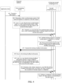
- FIG. 4 is a flowchart of interaction of interaction of a request processing method according to an embodiment of this application. As shown in FIG. 4 , this embodiment is applied to the clustered database which includes a first computing device and at least one second computing device.
- the first computing device refers to a computing device configured to process a data request, and all computing devices in a cluster except the first computing device are referred to as second computing devices.
- This embodiment includes the following steps 401 to 411.
- step 401 an application client transmits a data request to the first computing device in the clustered database.
- the clustered database may be applied to the request processing method no matter it is a centralized clustered database or a distributed clustered database, and this embodiment of this application only takes the distributed clustered database as an example.
- a user logs in to the application client on a terminal, and triggers the application client to generate the data request.
- the data request is a DDL request, or the data request is a DML request.
- a DDL request serving as the data request is taken as an example.
- the DDL request is to modify a table name of a data table A.
- the application client may invoke, after generating the data request, an API to transmit the data request to the first computing device.
- step 402 the first computing device determines a lock synchronization mode of the clustered database in response to the data request.
- step 402 is similar to the step 301, and will not be described in detail here.
- step 403 the first computing device locks, in a case that the lock synchronization mode is a weak lock synchronization mode, a data resource for the data request, and executes the data request.
- the lock synchronization mode is a weak lock synchronization mode
- step 403 is similar to the step 302, and will not be described in detail here.
- step 404 the first computing device transmits, in a case that the lock synchronization mode is not a weak lock synchronization mode, a locking request associated with the data request to the at least one second computing device in the clustered database.
- the lock synchronization mode may be a strong lock synchronization mode or a semi-strong lock synchronization mode.
- the first computing device needs to apply for a lock from all the remote second computing devices, and only target conditions of the two modes for determining a lock application success are different.
- a global application for the lock of the data resource succeeds only when all the second computing devices are required to apply for a lock successfully.
- the semi-strong lock synchronization mode the global application for the lock of the data resource succeeds if a target number or larger number of second computing devices apply for the lock successfully.
- the first computing device applies for a lock from the various second computing devices, to obtain the locking feedback information of the various second computing devices.
- the locking feedback information includes: a successful locking and a failed locking. There are usually various reasons for a failed locking: waiting timeout, deadlock, and the like.
- a message processing thread may be created in a background.
- the message processing thread may be specially used for processing various messages related to a locking mechanism, for example, monitoring locking requests, lock release requests, locking feedback information, lock release feedback information, and the like, of other computing devices, to timely receive and transmit the various messages related to the locking mechanism and ensure the communication performance between the computing devices.
- the first computing device may transmit the locking request to the message processing thread on the at least one second computing device via the message processing thread on the first computing device.
- any second computing device adds the locking request to a locking waiting queue in response to a locking request associated with the data request.
- the locking request is transmitted by the first computing device in the clustered database in a case that the lock synchronization mode is not the weak lock synchronization mode.
- the second computing device receives the locking request via the message processing thread; starts a lock agent thread for the locking request via the message processing thread; and adds the locking request to the locking waiting queue via the lock agent thread.
- each locking request corresponds to one lock agent thread, to reduce a waiting delay of each locking request.
- multiple locking requests may multiplex the same lock agent thread. In this case, locking requests arriving later need to be stored in the locking waiting queue. The various locking request stored in the locking waiting queue are processed by the lock agent thread in sequence.
- the message processing threads specially used for transmitting and receiving the lock-related messages are configured on both the first computing device and the second computing device, so that the message processing threads can start the lock agent thread to maintain a life cycle of a remote lock on each second computing device.
- the lock application thread on the first computing device has exited.
- the message processing thread of the first computing device may determine, by the following operation in step 408, whether the current data request is active and whether the locking feedback information indicates a successful locking, to timely return, in a case that the data request is not active, a lock release request to a second computing device that succeeds in locking and to trigger the remote lock that has been applied successfully, so as not to block services on the second computing device.
- step 406 the second computing device processes the locking request in the locking waiting queue to obtain locking feedback information, the locking feedback information indicates whether the second computing device successfully locks the data resource.
- the second computing device initiates a local lock agent thread and invokes a local lock application logic to process the various locking request cached in the locking waiting queue.
- the lock agent thread traverses the locking waiting queue. If locking of data resources for the data request transmitted by the first computing device at this time is completed, it indicates that the locking request has been processed, and the locking feedback information is determined as a successful locking. Otherwise, it is required to continue to wait in the locking waiting queue, and the locking feedback information is determined as a failed locking until waiting timeout or a deadlock occurs. That is, in a case that the waiting duration of the locking request in the locking waiting queue exceeds a third waiting threshold or deadlock detection fails, the locking feedback information is determined as the failed locking.
- the third waiting threshold is any value greater than 0. For example, the third waiting threshold is 5s.
- the third waiting threshold may also be added to the configuration file and is loaded by the database engine of each computing device upon startup of the clustered database.
- a deadlock detection process for the second computing device is as follows: the second computing device performs local deadlock detection on the locking request in response to a deadlock detection message of the first computing device; determines, in a case that the lock deadlock detection fails, that the deadlock detection fails; determines a lock waiting chain of the locking request in a case that the lock deadlock detection succeeds, the lock waiting chain including lock information that has a dependency relationship with the locking request; transmits, in a case that the lock waiting chain includes a remote lock, the deadlock detection message to a third computing device that initiates the remote lock, the remote lock being lock information that has been registered in the second computing device but is not initiated by the second computing device; and determines that the deadlock detection fails in a case that any computing device that transmits the deadlock detection message receives the deadlock detection message.
- the deadlock detection message may be initiated by the first computing device.
- the first computing device has not received the locking feedback information of each second computing device for a long time, but waiting is not timeout at this time, the message processing thread of the first computing device may transmit the deadlock detection message to the message processing thread of the second computing device.
- the second computing device first performs the local deadlock detection when receiving the deadlock detection message. If the local deadlock detection fails, the second computing device does not need to traverse the lock waiting chain, but directly returns the locking feedback information to the first computing device.
- the locking feedback information indicates a failed locking, and a failure type is that the second computing device is selected as a deadlock victim.
- the second computing device still needs to traverse the corresponding lock waiting chain, and determines whether each lock in the lock waiting chain is a remote lock is determined. If the lock is a remote lock, the second computing device transmits a deadlock detection message to a lock owner (namely, a third computing device) of the remote lock, and triggers the third computing device to execute a deadlock detection process similar to that of the second computing device. That is, the third computing device first performs local deadlock detection, then traverses remote locks in the lock waiting chain, and transmits a deadlock detection message again.
- a lock owner namely, a third computing device
- any computing device itself as a transmitting end of a deadlock detection message, receives the same deadlock detection message transmitted by other computing devices, it is indicated that a deadlock occurs.
- This computing device returns locking feedback information to the first computing device.
- the locking feedback information indicates a failed locking, and a failure type is that the computing device is selected as a deadlock victim.
- the first computing device transmits a deadlock detection message to the second computing device, and the second computing device determines that there is a remote lock on the lock waiting chain, and a lock owner of the remote lock is the first computing device.
- the second computing device transmits the deadlock detection message to the first computing device.
- a dependency ring phenomenon occurs, namely, a lock A waits for a lock B, and the lock B waits for the lock A. That is, the first computing device serving as a transmitting end of the deadlock detection message receives the same deadlock detection message transmitted by the second computing device, which indicates that a deadlock is found and the locking fails this time.
- the lock agent thread of the second computing device registers lock information for the data request in the message processing thread; determines whether the registered lock information is active lock information at an interval of a target duration; and transmits a keepalive detection request to the first computing device in a case that the lock information is active lock information and a locking duration of the data resource for the data request exceeds a keepalive detection threshold, the keepalive detection request is used for requesting the first computing device to indicate whether to release the data resource locked by the active lock information.
- the keepalive detection threshold may be any value greater than 0. For example, the keepalive detection threshold is 20s.
- the lock agent thread registers the corresponding lock information in the message processing thread, to facilitate the message processing thread to locally manage various successfully applied locks.
- the message processing thread may periodically check the active lock information in a registry. If the locking duration exceeds the keepalive detection threshold, the active lock information is still not released, which, for example, may be caused by the following several possibilities: i ) the execution of the data request of the first computing device is completed, but the transmitted lock release request is lost; ii) the lock application thread of the first computing device crashes; iii) the first computing device performs processing normally, but the current data request, such as the DDL transaction, takes long time.
- the first computing device may be triggered to transmit a lock release message again by transmitting the keepalive detection request, to instruct the second computing device to release the corresponding lock. If the active lock information is not released due to the above case iii), the second computing device cannot release the corresponding lock, and still needs to maintain the corresponding lock.
- step 407 the second computing device transmits the locking feedback information to the first computing device.
- the message processing thread of the second computing device transmits the locking feedback information to the message processing thread of the first computing device.
- steps 405 to 407 describe the process of applying for a remote lock by taking a single second computing device as an example, and operations similar to those in steps 405 to 407 can be performed on each second computing device in the cluster, which will not be described in detail here.
- step 408 the first computing device receives the locking feedback information returned by the at least one second computing device based on the locking request.
- the first computing device when receiving the locking feedback information, may receive, via the message processing thread on the first computing device, the locking feedback information returned by the message processing thread on the at least one second computing device.
- the first computing device may transmit the locking request to each second computing device in the cluster, and a time at which the locking feedback information of each second computing device is returned to the first computing device may be different.
- a processing process such as a DDL process
- the first computing device should timely instruct, according to the received locking feedback information, the second computing device that succeeds in locking to release the corresponding lock, which avoids blocking other DML processes on the data resource, thereby optimizing the processing performance of the clustered database.
- the first computing device may transmit, in response to receiving the locking feedback information of any second computing device, the locking feedback information to a lock application thread of the data request via the message processing thread in a case that the data request is in an active state; and the first computing device transmits a lock release request to the second computing device in a case that the data request is not in an active state and that the locking feedback information indicates successful locking, the lock release request is used for instructing the second computing device to release the data resource for the data request.
- the first computing device determines whether the local data request is active.
- a DDL request is taken as an example, and it may be determined whether a DDL process for the DDL request exists. Since there may be a case where multiple DDL requests multiplex the same DDL process, resulting in that the DDL process may still exist in a case that the current DDL request has failed (for example, a target condition is not met, and the DDL transaction is rolled back), there is a certain misjudgment in determining whether the DDL request is active with regard to the DDL process. In some embodiments, it may also be directly determined whether the DDL transaction for the DDL request is in an active state, which can effectively reduce the above misjudgment and improve the judgment accuracy.
- the first computing device can transmit the lock release request to the message processing thread of the second computing device via the message processing thread of the first computing device, to instruct the second computing device to release the data resource for the data request, for example, to modify the internal memory state parameter of the lock for the data resource to the idle state.
- no processing is required if the locking feedback information indicates failed locking, which means that the remote side does not have a data resource needing to be released in time.
- the locking feedback information may be transmitted to the lock application thread of the data request via the message processing thread, so that the lock application thread records the locking feedback information received this time, and determines, on the basis of following step 409, whether the locking feedback information meets a target condition, thereby facilitating the lock application thread to timely count whether the received locking feedback information meets a target condition in the current lock synchronization mode.
- Steps 404 to 408 described above shows how the first computing device obtains the locking feedback information of the data resource by the at least one second computing device in the clustered database.
- the first computing device may also directly transmit the locking request in a broadcast or multicast manner in the clustered database, and receive the locking feedback information returned by the various second computing devices.
- the first computing device and the second computing devices can directly communicate with each other by a lock application thread on the first computing device and lock agent threads on the second computing devices, without configuring the special message processing threads, which can reduce inter-thread communication expenses.
- step 409 the first computing device locks, in a case that the obtained locking feedback information meets a target condition in the lock synchronization mode, the data resource for the data request, and executes the data request.
- step 409 is similar to step 304, and will not be described in detail here.
- step 410 the first computing device transmits a lock release request to the at least one second computing device in a case that the obtained locking feedback information does not meet the target condition or the execution of the data request is completed.
- the lock release request is used for instructing the second computing device to release the data resource for the data request.
- the message processing thread of the first computing device transmits a lock release request to the message processing threads of the various second computing devices.
- a transmitting process of the lock release request is the same as the transmitting process of the locking request, and will not be described in detail here.
- any second computing device releases, in response to the lock release request associated with the data request, the data resource for the data request.
- the message processing thread of the second computing device receives the lock release request, and notifies the lock agent thread to release the corresponding data resource.
- the lock agent thread modifies an internal memory state parameter of a lock to an idle state, and clears corresponding lock information in a registry. So far, the message processing has been completed, and the various received messages are discarded to save a storage space.
- a weak lock synchronization mode by setting multiple flexible levels for lock synchronization modes, in a weak lock synchronization mode, a data resource for a data request is directly locked, and the data request is executed, which can ensure that the data request is advanced preferentially, without waiting for a response of a second computing device.
- a non-weak lock synchronization mode locking feedback information of various second computing devices is obtained. In a case that the obtained locking feedback information meets a target condition, the data resource is locked, and the data request is executed.
- Different lock synchronization modes can be selected in different service scenarios, thereby ensuring that a clustered database can meet processing requirements of different service scenarios, which improves the processing capability of a clustered database system.
- FIG. 5 is a schematic diagram of a principle of a locking process according to an embodiment of this application.
- a clustered database includes a computing node 1 and a computing node 2.
- the computing node 1 is a first computing device, and a lock application thread and a message processing thread are run on the computing node 1, and the computing node 2 is a second computing device, and a message processing thread and a lock agent thread are run on the computing node 2.
- a DDL request serving as a data request is taken as an example.
- a global locking process is performed.
- the global locking process is described in detail below which includes the following steps 1 to 32.
- step 1 the lock application thread of the computing node 1 first completes the local lock application, and then performs a locking process.
- step 2 the lock application thread of the computing node 1 determines whether it is in a weak lock synchronization mode; directly determine, if it is in the weak lock synchronization mode, that a lock has been obtained (the correctness is guaranteed by a writing fence mechanism) without transmitting a locking application to other nodes, and performs step 28; and performs step 3 if it is not in the weak lock synchronization mode.
- step 3 if it is not in the weak lock synchronization mode, the lock application thread of the computing node 1 transmits a locking request to other nodes, performs step 4, and performs step 26 to start time counting.
- step 4 the message processing thread of the computing node 2 receives the locking request.
- the message processing thread specially monitors locking requests, lock release requests, and locking feedback information of other nodes in the background, and is used for receiving and transmitting various types of lock-related messages.
- the message processing thread invokes the lock agent thread to maintain the life cycle of a remote lock on the computing node 2.
- the lock application thread of the application end may have crashed or exited when the locking feedback information arrives at an application end (the computing node 1)
- the message processing thread on the computing node 1 may determine, according to whether the lock application thread has exited and whether the locking feedback information indicates a successful locking, whether to transmit a lock release request to the computing node 2, to release the remote lock of the remote end which has been successfully applied.
- step 5 the computing node 2 starts a local lock agent thread and invokes a local application lock logic.
- step 6 the computing node 2 determines whether a lock for the DDL request is successfully applied, performs, if the application succeeds, step 8, and performs the following steps if the application fails: 6.1) the locking request is still in a locking waiting queue and waits in the queue, and continues to wait at this moment, and step 7 is performed to determine whether timeout occurs; 6.2) a deadlock is found in deadlock detection, and the computing node is selected as a deadlock victim and performs step 8.
- step 7 the computing node 2 determines whether the remote lock application has timed out, continues to wait if the remote lock application has not timed out, and performs step 8 if the remote lock application has timed out.
- a waiting duration exceeds a third waiting threshold is determined.
- step 8 the computing node 2 transmits locking feedback information to the message processing thread of the computing node 1, and performs step 10.
- the locking feedback information may be divided into three categories: successful locking, lock waiting timeout, and deadlock victim.
- the locking feedback information may be divided into two categories: a successful locking and a failed locking.
- the failed locking includes: lock waiting timeout and deadlock victim.
- a message feedback interface of the message processing thread of the computing node 2 mainly processes a keepalive detection request initiated by the keepalive detection mechanism of steps 10 to 13, and transmits the keepalive detection request to the message processing thread of the computing node 1.
- the keepalive detection request is directed to such a case that the lock application thread of the lock application end (the computing node 1) has exited, but the remote lock of the computing node 2 has not been released all the time. In a case that the remote lock has not been released beyond a certain time period (for example, the keepalive detection threshold), the keepalive detection request is transmitted to the lock application end, namely, the lock owner, for keepalive detection.
- a certain time period for example, the keepalive detection threshold
- step 10 the lock agent thread of the computing node 2 registers lock information and lock states for all remote locks in the message processing thread.
- the lock information includes but is not limited to: a lock type (read lock, write lock, update lock, and the like), a data resource (such as a database name, a data table name, a data index ID, and a data column name) for a lock, locking time, and the like.
- a lock type read lock, write lock, update lock, and the like
- a data resource such as a database name, a data table name, a data index ID, and a data column name
- the lock states include but are not limited to: an active state, an inactive state, and the like.
- step 11 the message processing thread of the computing node 2 periodically checks active locks among the various remote locks in a registry.
- each piece of lock information in the registry is traversed to query for remote locks in active states.
- step 12 the computing node 2 determines whether there is a remote active lock exceeding the keepalive detection threshold; if so, performs step 13; and if no, continues to periodically monitor the lock information in the registry.
- step 13 the computing node 2 prepares to feed back the keepalive detection request, and performs step 9.
- step 14 the message processing thread of the computing node 1 receives the locking feedback information and the keepalive detection request.
- step 15 the computing node 1 determines whether the local lock application thread is active, performs step 16 if no, and performs step 21 if yes.
- the active state there may be three cases: 15.1) if the current lock application thread is active in a lock application stage, corresponding lock application structure data is updated and transmitted to the lock application thread for processing; 15.2) if the current lock application thread has reached a target condition of a lock application success in the semi-strong lock synchronization mode, corresponding lock application structure data is updated, and the operation is completed; 15.3) if the current lock application thread is in a lock exited state or exits in a lock application failure (for example, it has been determined that the target condition is not met in the semi-strong lock synchronization mode), corresponding lock application structure data is updated, and the operation is completed.
- the lock application structure data is used for recording locking feedback information of the various computing nodes 2, for example, in the form of a hash table, an array, a set, a vector, and the like.
- a set form is used.
- Each element in the set indicates whether a computing node succeeds or fails in locking.
- Element 0 indicates a failed locking.
- Element 1 indicates a successful locking.
- Element null indicates that no locking feedback information is received.
- step 16 if the locking feedback information at this moment indicates a successful locking, or the keepalive detection request is received, the computing node 1 performs step 17. Otherwise, no processing is performed, and step 32 is performed, namely, the message processing is completed, and this received message is discarded.
- step 17 the message processing thread of the computing node 1 transmits a lock release request to the message processing thread of the computing node 2.
- step 18 the message processing thread of the computing node 2 receives the lock release request.
- step 19 the message processing thread of the computing node 2 notifies the lock agent thread to release the lock.
- step 20 the lock agent thread of the computing node 2 releases the lock.
- step 21 the lock application thread of the computing node 1 receives the locking feedback information transmitted by the message processing thread, which includes several types of locking feedback information involved step 8.
- step 22 the computing node 1 determines the current lock synchronization mode, performs step 25 if the current lock synchronization mode is a strong lock synchronization mode, and performs step 23 if the current lock synchronization mode is a semi-strong lock synchronization mode.
- step 23 the computing node 1 checks whether a successful locking probability parameter lock_succ_node_num is set as a valid value (namely, greater than or equal to 1 and less than or equal to the number of all the computing devices in the cluster), performs step 24 according to the semi-strong lock synchronization mode if the successful locking probability parameter lock_succ_node_num is a valid value, and performs step 25 according to the strong lock synchronization mode if the successful locking probability parameter lock_succ_node_num is not a valid value.
- step 24 the computing node 1 determines whether the number of remote nodes that feed back successful locking plus the number of the local node exceeds the successful locking probability parameter lock_succ_node_num; performs step 28 if yes; determines, if no, whether the lock application times out, that is, whether the waiting duration exceeds the second waiting threshold; continues to wait if no waiting timeout occurs; displays a failed locking if waiting timeout occurs; and if the number of the remote nodes that feed back failed locking has exceeded a value obtained by subtracting the successful locking probability parameter lock_succ_node_num from the total number of the nodes in the cluster, determines a failed locking, and performs step 29.
- step 25 the computing node 1 needs to determine, in the strong lock synchronization mode, whether all the nodes feed back a locking succeed; performs step 28 if the above condition is met; continues to wait if the condition is not met but no waiting timeout occurs, namely, if the waiting duration does not exceed a first waiting threshold; and determines a failed locking if any node feeds back a failed locking, and performs step 29.
- step 26 the computing node 1 starts to calculate lock application time.
- step 27 the computing node 1 determines whether the lock application time has timed out; performs step 29, namely, determines a failed locking, if yes; and performs step 21 to check the logic if no.
- a timeout threshold in the strong lock synchronization mode is the first waiting threshold
- a timeout threshold in the semi-strong lock synchronization mode is the second waiting threshold. Values of the two timeout thresholds may be the same or different.
- step 28 the computing node 1 determines a successful global locking.
- step 29 the computing node 1 determines a failed global locking.
- step 30 the computing node 1 transmits a lock release request to all other nodes.
- the computing node 1 since the keepalive detection logic of steps 11-20 exists on other nodes, after transmitting the lock release request, the computing node 1 can end the process without waiting for other nodes to return lock release feedback information.
- step 31 the computing node 1 completes the locking process.
- step 32 after the message processing is completed, the messages are discarded.
- a flexible lock mechanism can be implemented in the distributed database to ensure the correctness of operations for modifying a certain data resource by various processes or threads.
- the weak lock synchronization mode, the semi-strong lock synchronization mode, and the strong lock synchronization mode can be flexibly switched by means of the implementation of the flexible lock mechanism, so that a distributed database cluster can select lock mechanisms at different levels according to requirements of its own database application scenarios, to meet service requirements of users in different service scenarios.
- FIG. 6 is a schematic diagram of a principle of a lock release process according to an embodiment of this application.
- a clustered database includes a computing node 1 and a computing node 2.
- the computing node 1 is a first computing device
- the computing node 2 is a second computing device
- a message processing thread and a lock agent thread are run on the computing node 2.
- the computing node 1 executes a corresponding data request, such as a DDL request.
- the computing node 1 may enter a lock release process.
- the lock release process is described in detail below which includes the following steps 1 to 11.
- step 1 after the local DDL transaction processing logic is completed, the computing node 1 enters a lock release process.
- an order of releasing a remote lock first and then releasing a local lock is taken as an example to describe the process of global lock release.
- an overall process of locking and lock release is as follows: local locking ⁇ remote locking ⁇ remote lock release ⁇ local lock release.
- step 2 the computing node 1 determines whether it is in a weak lock synchronization mode, and performs step 10 if it is in a weak lock synchronization mode, without releasing a remote lock, and performs step 3 if it is not in a weak lock synchronization mode.
- step 3 the computing node 1 transmits a lock release request to all other nodes.
- step 4 the message processing thread of the computing node 2 receives the lock release request.
- step 5 the message processing thread initiates the lock agent thread to locally release the corresponding remote lock.
- the message processing thread wakes up the lock agent thread and performs a lock release operation.
- step 6 the lock agent thread locally releases the corresponding remote lock, performs step 7 if the release succeeds, and re-releases the corresponding remote lock if the release fails.
- step 7 the computing node 1 prepares to clear corresponding lock information in a registry.
- step 8 the computing node 1 clears lock information that has been registered in the registry.
- step 9 the lock agent thread exits.
- step 10 the lock is released successfully.
- step 11 the lock release process ends.
- FIG. 7 is a schematic diagram of a principle of a deadlock detection process according to an embodiment of this application.
- a clustered database includes a computing node 1 and a computing node 2.
- the computing node 1 is a first computing device
- the computing node 2 is a second computing device
- a message processing thread is run on the computing node 2.
- the deadlock detection process is described below which includes the following steps 1 to 10.
- step 1 the computing node 1 intends to lock a data resource A.
- step 2 the computing node 1 transmits a deadlock detection message to other nodes, and performs step 3 and step 10.
- step 3 the message processing thread of the computing node 2 receives the deadlock detection message.
- the deadlock detection message includes relevant lock information.
- step 4 the computing node 2 applies a local deadlock detection logic to perform local deadlock detection; performs step 5 if the deadlock detection succeeds; and returns, if the deadlock detection fails, a message indicating that the computing node itself is selected as a deadlock victim.
- step 5 the computing node 2 traverses a lock waiting chain.
- step 6 the computing node determines whether a current lock in the lock waiting chain is a remote lock; performs step 7 if the current lock is a remote lock; and traverses a next lock on the lock waiting chain if the current lock is not a remote lock.
- step 7 the computing node 2 transmits the deadlock detection message to a lock owner.
- the lock owner is described by taking the computing node 1 as an example.
- step 8 the computing node 1 receives the deadlock detection message.
- step 9 if it is found that the deadlock detection message forms a closed loop, a deadlock is generated.
- step 10 the computing node 1 registers lock information on the local message processing thread.
- the local deadlock detection logic needs to be performed, and adaptation is also performed on the distributed database.
- a lock is a remote lock is determined; if the lock is not a remote lock, whether a deadlock is generated can be found in the local deadlock detection logic; if the lock is a remote lock, a deadlock detection message is transmitted to a lock owner (namely, a computing node where a lock holding thread is located); and if the node that owns the lock and the computing node that initiates the deadlock detection are the same node, it indicates that a closed loop is formed, namely, a deadlock is generated.
- a lock owner namely, a computing node where a lock holding thread is located
- the computing node 1 waits for the computing node 2, and the computing node 2 waits for the computing node 1, forming a closed loop.
- the database engine may automatically retry after an interval of a time period, or returns a rejection message to the user, and the user retries after waiting for a time period.
- a weak lock synchronization mode since the weak lock synchronization mode does not need to apply for a lock from a remote end, and the correctness of a resource operation is guaranteed by a writing fence mechanism, it is equivalent to that a DDL transaction which needs to apply for a lock has a higher priority.
- a DML transaction of a user may be rolled back, while the DML transaction is generally a key service of the user, therefore, in some scenarios, the user experience is poor, but the weak lock synchronization mode is applicable to application scenarios with many DDL transactions.
- a compromise can be provided. That is, a flexible and configurable cluster running mode can be provided between the influence caused by the above-mentioned network problem of a distributed system and a high demand of users for service execution success.
- lock_succ_node_num n
- n is the total number of the nodes, namely, the computing devices, in the cluster, and it is actually equivalent to the strong lock synchronization mode. If 0 ⁇ lock_succ_node_num ⁇ n, it is equivalent to the semi-strong lock synchronization mode.
- the administrator may set a reasonable value according to a network condition of its own cluster, to ensure to the maximum extent that DML transactions of users can be treated fairly with DDL transactions.
- no response of one or more nodes will not cause the whole cluster unavailable, for example, cause the whole cluster hung.
- steps 10 to 20 in the above-mentioned locking process also provide a keepalive detection mechanism, to ensure that a remote node can actively perform, in a case that a lock release request cannot be transmitted to other nodes for some reasons, keepalive detection by means of a keepalive detection mechanism, to release a remote lock.
- the administrator is provided with a flexible adjustment manner for determining a lock synchronization mode according to a network environment in which a distributed database cluster is run and requirements for a DML transaction success rate, so that the user can use the computing capability of the distributed cluster to the maximum extent, and various nodes of the distributed cluster can perform like a database system of a single node in a running process.
- FIG. 8 is a schematic structural diagram of a request processing apparatus according to an embodiment of this application.
- the apparatus includes: a determining module 801, configured to determine a lock synchronization mode of the clustered database in response to a data request; a locking execution module 802, configured to lock a data resource for the data request and execute the data request in a case that the lock synchronization mode is a weak lock synchronization mode; and a first obtaining module 803, configured to obtain locking feedback information of the data resource by at least one second computing device in the clustered database in a case that the lock synchronization mode is not the weak lock synchronization mode, the locking feedback information indicating whether the second computing device successfully locks the data resource.
- the locking execution module 802 is further configured to lock the data resource for the data request in a case that the obtained locking feedback information meets a target condition in the lock synchronization mode, and execute the data request.
- a weak lock synchronization mode by setting multiple flexible levels for lock synchronization modes, in a weak lock synchronization mode, a data resource for a data request is directly locked, and the data request is executed, which can ensure that the data request is advanced preferentially, without waiting for a response of a second computing device.
- a non-weak lock synchronization mode locking feedback information of various second computing devices is obtained. In a case that the obtained locking feedback information meets a target condition, the data resource is locked, and the data request is executed.
- Different lock synchronization modes can be selected in different service scenarios, thereby ensuring that a clustered database can meet processing requirements of different service scenarios, thus improving the processing capability of a clustered database system.
- the first obtaining module 803 includes: a transmission unit, configured to transmit a locking request associated with the data request to the at least one second computing device; and a receiving unit, configured to receive the locking feedback information returned by the at least one second computing device on the basis of the locking request.
- the transmitting unit is configured to: transmit the locking request to a message processing thread on the at least one second computing device via a message processing thread on the first computing device.
- the receiving unit is configured to: receive, via the message processing thread on the first computing device, the locking feedback information returned by the message processing thread on the at least one second computing device.
- the apparatus further includes: a transmission module, configured to transmit, in response to receiving the locking feedback information of any second computing device, the locking feedback information to a lock application thread of the data request via the message processing thread in a case that the data request is in an active state.
- the transmission module is further configured to transmit a lock release request to the second computing device in a case that the data request is not in an active state and that the locking feedback information indicates a successful locking, the lock release request is used for instructing the second computing device to release the data resource for the data request.
- the target condition is that the locking feedback information of the at least one second computing device indicates a successful locking.
- the target condition is that the locking feedback information of a target number or a larger number of second computing devices among the at least one second computing device indicates a successful locking.
- the target condition is that the waiting duration does not exceed the first waiting threshold, and the locking feedback information of the at least one second computing device indicates a successful locking.
- the target condition is that the waiting duration does not exceed the second waiting threshold and the locking feedback information of a target number or larger number of second computing devices among the at least one second computing device indicates a successful locking.
- the apparatus further includes: a second obtaining module, configured to obtain the target number in a case that the lock synchronization mode is the semi-strong lock synchronization mode; and a switching module, configured to switch the lock synchronization mode to the strong lock synchronization mode in a case that the target number is less than one or greater than the number of all the second computing devices in the clustered database.
- the apparatus further includes: a transmission module, configured to transmit a lock release request to the at least one second computing device in a case that the obtained locking feedback information does not meet the target condition or the execution of the data request is completed, the lock release request being used for instructing the second computing device to release the data resource for the data request.
- a transmission module configured to transmit a lock release request to the at least one second computing device in a case that the obtained locking feedback information does not meet the target condition or the execution of the data request is completed, the lock release request being used for instructing the second computing device to release the data resource for the data request.
- the data request is a DDL request.
- the request processing apparatus provided by the above embodiment is only illustrated by dividing the functional modules above when processing the data request.
- the foregoing functions may be allocated to and completed by different functional modules as required, that is, an inner structure of a computing device is divided into different functional modules, so as to complete all or some of the functions described above.
- the request processing apparatus and the request processing method provided in the above embodiments belong to the same idea. Details of specific implementation processes of the apparatus refer to the request processing method embodiment, and are not described here again.
- FIG. 9 is a schematic structural diagram of a request processing apparatus according to an embodiment of this application.
- the apparatus includes: an adding module 901, configured to add the locking request to a locking waiting queue in response to a locking request associated with a data request, the locking request being transmitted by a first computing device in the clustered database in a case that a lock synchronization mode is not a weak lock synchronization mode; a processing module 902, configured to process the locking request in the locking waiting queue to obtain locking feedback information; and a transmission module 903, configured to transmit the locking feedback information to the first computing device.
- an adding module 901 configured to add the locking request to a locking waiting queue in response to a locking request associated with a data request, the locking request being transmitted by a first computing device in the clustered database in a case that a lock synchronization mode is not a weak lock synchronization mode
- a processing module 902 configured to process the locking request in the locking waiting queue to obtain locking feedback information
- a transmission module 903 configured to transmit the locking feedback information
- the first computing device will transmit a locking request if it is not in a weak lock synchronization mode, so that corresponding locking feedback information is returned in response to the locking request.
- the first computing device is triggered to lock the data resource and execute the data request. Therefore, the clustered database supports to select different lock synchronization modes in different service scenarios, thereby ensuring that a clustered database can meet processing requirements of different service scenarios, thus improving the processing capability of a clustered database system.
- the processing module 902 is configured to: lock a data resource for the data request, and determine that the locking feedback information indicates a successful locking; and determine that the locking feedback information indicates a failed locking in a case that a waiting duration of the locking request in the locking waiting queue exceeds a third waiting threshold or that deadlock detection fails.
- the apparatus further includes: a detection module, configured to perform local deadlock detection on the locking request in response to a deadlock detection message of the first computing device; a first determining module, configured to determine, in a case that the lock deadlock detection fails, that the deadlock detection fails; and a second determining module, configured to determine a lock waiting chain of the locking request in a case that the lock deadlock detection succeeds, the lock waiting chain including lock information that has a dependency relationship with the locking request.
- a detection module configured to perform local deadlock detection on the locking request in response to a deadlock detection message of the first computing device
- a first determining module configured to determine, in a case that the lock deadlock detection fails, that the deadlock detection fails
- a second determining module configured to determine a lock waiting chain of the locking request in a case that the lock deadlock detection succeeds, the lock waiting chain including lock information that has a dependency relationship with the locking request.
- the transmission module 903 is further configured to transmit, in a case that the lock waiting chain includes a remote lock, the deadlock detection message to a third computing device that initiates the remote lock, the remote lock being lock information that has been registered in the second computing device but is not initiated by the second computing device.
- the first determining module is further configured to determine that the deadlock detection fails: in a case that any computing device that transmits the deadlock detection message receives the deadlock detection message.
- the adding module 901 is configured to: receive the locking request via a message processing thread on the second computing device; start a lock agent thread for the locking request via the message processing thread; and add the locking request to the locking waiting queue via the lock agent thread.
- the apparatus further includes: a registration module, configured to register lock information for the data request in a case that the data resource for the data request is locked; and a third determining module, configured to determine whether the lock information is active lock information at an interval of a target duration.
- the transmission module 903 is further configured to transmit a keepalive detection request to the first computing device in a case that the lock information is active lock information and a locking duration of the data resource for the data request exceeds a keepalive detection threshold, the keepalive detection request is used for requesting the first computing device to indicate whether to release the data resource.
- the apparatus further includes: a release module, configured to release, in response to the lock release request associated with the data request, the data resource for the data request.
- the request processing apparatus in the above embodiment is only illustrated by dividing the functional modules above when processing the data request.
- the foregoing functions may be allocated to and completed by different functional modules as required, that is, an inner structure of a computing device is divided into different functional modules, so as to complete all or some of the functions described above.
- the request processing apparatus and the request processing method provided in the above embodiments belong to the same idea. Details of specific implementation processes of the apparatus refer to the request processing method embodiment, and are not described here again.
- FIG. 10 is a schematic structural diagram of a computing device according to an embodiment of this application.
- the computing device is described by taking a terminal 1000 as an example.
- a device type of the terminal 1000 includes: a smart phone, a tablet computer, an MP3 (Moving Picture Experts Group Audio Layer III) player, an MP4 (Moving Picture Experts Group Audio Layer IV) player, a notebook computer or a desktop computer.
- the terminal 1000 may also be referred to as another name such as user equipment, a portable terminal, a laptop terminal, or a desktop terminal.
- the terminal 1000 includes: a processor 1001 and a memory 1002.
- the processor 1001 includes one or more processing cores, for example, a 4-core processor or an 8-core processor.
- the processor 1001 is implemented in at least one hardware form of Digital Signal Processing (DSP), a Field-Programmable Gate Array (FPGA), a Programmable Logic Array (PLA).
- DSP Digital Signal Processing
- FPGA Field-Programmable Gate Array
- PPA Programmable Logic Array
- the processor 1001 includes a main processor and a coprocessor.
- the main processor is a processor configured to process data in an awake state, and is also referred to as a central processing unit (CPU).
- the coprocessor is a low power consumption processor configured to process the data in a standby state.
- the processor 1001 is integrated with a graphics processing unit (GPU).
- the GPU is configured to render and draw content that needs to be displayed on a display screen.
- the processor 1001 further includes an artificial intelligence (AI) processor.
- the AI processor is configured to process computing operations related to machine learning.
- the memory 1002 includes one or more computer-readable storage media.
- the computer-readable storage media are non-transitory.
- the memory 1002 also includes a high speed random access memory, and a non-volatile memory, such as one or more magnetic disk storage devices and flash storage devices.
- the non-transitory computer-readable storage medium in the memory 1002 is configured to store at least one program code which is used for being executed by the processor 1001 to implement the request processing methods provided in the various method embodiments of this application.
- the terminal 1000 may also in some embodiments include: a peripheral interface 1003 and at least one peripheral.
- the processor 1001, the memory 1002, and the peripheral interface 1003 can be connected through a bus or a signal cable.
- Each peripheral can be connected to the peripheral interface 1003 through a bus, a signal cable, or a circuit board.
- the peripheral includes: at least one of a radio frequency circuit 1004, a display screen 1005, a camera component 1006, an audio circuit 1007, a positioning component 1008, and a power supply 1009.
- the terminal 1000 further includes one or more sensors 1010.
- the one or more sensors 1010 include but are not limited to: an acceleration sensor 1011, a gyroscope sensor 1012, a pressure sensor 1013, a fingerprint sensor 1014, an optical sensor 1015, and a proximity sensor 1016.
- FIG. 10 is not a limitation of the terminal 1000 and can include more or fewer components than shown, or combine certain components, or employ a different arrangement of components.
- FIG. 11 is a schematic structural diagram of a computing device according to an embodiment of this application.
- the computing device 1100 may vary a lot due to different configurations or performances.
- the computing device 1100 includes one or more CPUs 1101 and one or more memories 1102.
- the memory 1102 stores at least one computer program, and the at least one computer program is loaded and executed by the one or more CPUs 1101 to implement the request processing methods provided in all the above embodiments.
- the computing device 1100 also includes components such as a wired or wireless network interface, a keyboard, and an input/output interface, to facilitate inputting and outputting.
- the computing device 1100 further includes other components for realizing the functions of the device, which will not be described in detail herein.
- a computer-readable storage medium is further provided, for example, a memory including at least one computer program.
- the at least one computer program can be executed by a processor in a terminal to implement the request processing methods in the above embodiments.
- the computer-readable storage medium includes a Read-Only Memory (ROM), a Random-Access Memory (RAM), a Compact Disc Read-Only Memory (CD-ROM), a magnetic tape, a floppy disk, an optical data storage device, and the like.
- a computer program product or computer program is further provided, including one or more program codes stored in a computer-readable storage medium.
- One or more processors of a computing device can read the one or more program codes from a computer-readable storage medium, the one or more processors executing the one or more program codes to enable the computing device to implement the request processing methods in the above embodiments.
- the program is stored in a computer-readable storage medium.
- the storage medium mentioned above is an ROM, a magnetic disk, an optical disk, or the like.
Landscapes
- Engineering & Computer Science (AREA)
- Theoretical Computer Science (AREA)
- Software Systems (AREA)
- Physics & Mathematics (AREA)
- General Engineering & Computer Science (AREA)
- General Physics & Mathematics (AREA)
- Databases & Information Systems (AREA)
- Data Mining & Analysis (AREA)
- Computing Systems (AREA)
- Information Retrieval, Db Structures And Fs Structures Therefor (AREA)
Abstract
Description
- This application claims priority to
Chinese Patent Application No. 2021110037642, filed with the China National Intellectual Property Administration on August 30, 2021 - This application relates to the technical field of databases, and in particular to a request processing technology.
- With the development of the database technology, a traditional stand-alone database cannot adapt to big data, cloud computing, and other service scenarios, and clustered databases become more and more popular. At present, the stand-alone database such as MySQL and PostgreSQL and the clustered database such as IBM and Oracle both adopt a concurrency control method based on a strong synchronization locking mechanism, and the strong synchronization locking mechanism refers to that application for locks is succeed only when locks of corresponding levels are obtained in all computing devices in a cluster in the process of applying for locks; otherwise, the application process needs to wait. This process of applying for locks will fail as long as any one of the computing devices in the cluster fails to apply a lock or the waiting is timeout.
- In the clustered database, the strong synchronization locking mechanism requires all the computing devices in the cluster to obtain the locks of the corresponding levels. As the number of computing devices in the cluster increases, the cost of applying for locks increases significantly, which leads to a low processing capability of a clustered database system. Therefore, there is an urgent need for a method that can improve the processing capability of the clustered database system.
- Request processing methods and apparatuses, a computing device and a storage medium are provided according to embodiments of this application, which can improve the processing capability of the clustered database. The technical solutions are described as follows.
- In one aspect, a request processing method is provided, which is performed by a first computing device in a clustered database and includes:
- determining a lock synchronization mode of the clustered database in response to a data request;
- locking a data resource for the data request, and executing the data request, in a case that the lock synchronization mode is a weak lock synchronization mode;
- obtaining locking feedback information of the data resource by at least one second computing device in the clustered database in a case that the lock synchronization mode is not the weak lock synchronization mode, the locking feedback information indicating whether the second computing device successfully locks the data resource; and locking, in a case that the obtained locking feedback information meets a target condition in the lock synchronization mode, the data resource for the data request, and executing the data request.
- In one aspect, a request processing method is provided, which is performed by a second computing device in a clustered database and includes:
- adding, in response to a locking request associated with a data request, the locking request to a locking waiting queue, wherein the locking request is transmitted by a first computing device in the clustered database in a case that a lock synchronization mode is not a weak lock synchronization mode;
- processing the locking request in the locking waiting queue to obtain locking feedback information; and
- transmitting the locking feedback information to the first computing device.
- In one aspect, a request processing apparatus is provided, which includes:
- a determining module, configured to determine a lock synchronization mode of a clustered database in response to a data request;
- a locking execution module, configured to lock a data resource for the data request and execute the data request in a case that the lock synchronization mode is a weak lock synchronization mode; and
- a first obtaining module, configured to obtain locking feedback information about the data resource by at least one second computing device in the clustered database in a case that the lock synchronization mode is not the weak lock synchronization mode, the locking feedback information indicating whether the second computing device successfully locks the data resource, and where
- the locking execution module is further configured to lock the data resource for the data request in a case that the obtained locking feedback information meets a target condition in the lock synchronization mode, and execute the data request.
- In one aspect, a request processing apparatus is provided, which includes:
- an adding module, configured to add, in response to a locking request associated with a data request, the locking request to a locking waiting queue, where the locking request is transmitted by a first computing device in the clustered database in a case that a lock synchronization mode is not a weak lock synchronization mode;
- a processing module, configured to process the locking request in the locking waiting queue to obtain locking feedback information; and
- a transmission module, configured to transmit the locking feedback information to the first computing device.
- In one aspect, a computing device is provided, which includes one or more processors and one or more memories, the one or more memories storing at least one computer program which is loaded and executed by the one or more processors to implement the request processing method of any one of the above possible implementations.
- In one aspect, a storage medium is provided, which stores at least one computer program, the computer program being loaded and executed by a processor to implement the request processing method of any one of the above possible implementations.
- In one aspect, a computer program product or a computer program is provided, the computer program product or the computer program including one or more program codes which are stored in a computer-readable storage medium. One or more processors of a computing device can read the one or more program codes from a computer-readable storage medium, the one or more processors executing the one or more program codes to enable the computing device to implement the request processing method of any one of the above possible implementations.
- The technical solutions of the embodiments of this application can realize at least the following beneficial effects. By means of setting a plurality of flexible levels for lock synchronization modes, in a weak lock synchronization mode, a data resource for a data request is directly locked, and the data request is executed, which can ensure that the data request is advanced preferentially, without waiting for a response of a second computing device. In a non-weak lock synchronization mode, locking feedback information of various second computing devices is obtained. In a case that the obtained locking feedback information meets a target condition, the data resource is locked, and the data request is executed. Different lock synchronization modes can be selected in different service scenarios, thereby ensuring that a clustered database can meet processing requirements of different service scenarios, which improves the processing capability of a clustered database system.
-
-
FIG. 1 is a schematic diagram of an implementation environment of a request processing method according to an embodiment of this application. -
FIG. 2 is a schematic diagram of a principle of a lock synchronization mechanism model according to an embodiment of this application. -
FIG. 3 is a flowchart of a request processing method according to an embodiment of this application. -
FIG. 4 is a flowchart of interaction of a request processing method according to an embodiment of this application. -
FIG. 5 is a schematic diagram of a principle of a locking process according to an embodiment of this application. -
FIG. 6 is a schematic diagram of a principle of a lock release process according to an embodiment of this application. -
FIG. 7 is a schematic diagram of a principle of a deadlock detection process according to an embodiment of this application. -
FIG. 8 is a schematic structural diagram of a request processing apparatus according to an embodiment of this application. -
FIG. 9 is a schematic structural diagram of a request processing apparatus according to an embodiment of this application. -
FIG. 10 is a schematic structural diagram of a computing device according to an embodiment of this application. -
FIG. 11 is a schematic structural diagram of a computing device according to an embodiment of this application. - To make the objectives, technical solutions, and advantages of this application clearer, the following further describes implementations of this application in detail with reference to the accompanying drawings.
- The terms "first", "second", and the like are used herein to distinguish the same or similar items that perform substantially the same function, and it is to be understood that the terms "first", "second", and "nth" do not have a logical or chronological dependency on each other or limit the number and order of execution.
- The term "at least one" in this application means one or more, and the term "plurality" means two or more. For example, a plurality of first positions mean two or more first positions.
- Before introducing the embodiments of this application, some basic concepts in the field of cloud technologies are introduced below.
- Cloud Technology refers to a hosting technology that unifies series resources such as hardware, software, and networks in a wide area network or a local area network to achieve computation, storage, processing, and sharing of data. The cloud technology is a general name of a network technology, an information technology, an integration technology, a management platform technology, an application technology, and the like applied on the basis of a cloud computing service mode, which can form a resource pool for on-demand use, and is flexible and convenient. A cloud computing technology is an important support in the field of the cloud technology. Background services of a technical network system require a large amount of computing and storage resources, such as video websites, image websites, and more portal websites. With the high development and application of the Internet industry, each article may have an own identification mark which needs to be transmitted to a background system for logic processing. Data of different levels will be processed separately, and various kinds of industry data need a strong system backing support, which can be achieved through cloud computing.
- Cloud Storage is a new concept that expands and develops on cloud computing. A distributed cloud storage system (hereinafter referred to as storage system) refers to a storage system which integrates a large number of different types of storage devices (storage devices are also referred to as storage nodes) in a network through functions of a cluster application, a grid technology, and a distributed storage file system to work together through application software or application interfaces, to provide data storage and service access functions together.
- Database may be regarded as an electronic file cabinet, namely, a place for storing electronic documents, and users may perform operations on data such as addition, query, update, and deletion. The so-called "database" is a data set that is stored together in a manner and can be shared with many users, has a redundancy as little as possible, and is independent of application programs.
- Terms involved in the embodiments of this application will be explained below.
- Computing device a computing node, which refers to a node device in a database (which is usually referred to as a clustered database. For a stand-alone database, a stand-alone device itself is a computing device), which is used for processing a user-specific computing request and is mainly configured to execute a user request. The computing device may also be referred to as an SQL engine. SQL is short for Structured Query Language.
- Locking mechanism: during the running of a clustered database, on different computing devices or the same computing, there will be a phenomenon that different processes or threads need to modify the same data resource at the same time (for example: a database, a data table, a data column, and data index). The locking mechanism can ensure the modification correctness of the data resource in different concurrent processes or threads. The clustered database can be divided into a central clustered database and a distributed clustered database. The central clustered database refers to a clustered database having a centralized control module, and the distributed clustered database refers to a decentralized clustered database.
- Strong synchronization locking mechanism refers to that application for locks will be succeed only when locks of corresponding levels are obtained in all computing devices in a cluster in process of applying for locks; otherwise, the application process needs to wait. This process will fail in applying for locks as long as any one of the computing devices in the cluster fails to apply for a lock.
- The strong synchronization locking mechanism has an extremely high requirement for inter-node (namely, inter-computing device) communication performance. As a result, executions of other computing devices in a cluster are easily blocked by a single computing device because of no response or fault of this computing device, so that it is seen from the outside that the service processing capability of the whole cluster obviously decreases. For example, the service processing of the whole cluster is hung. In general, the strong synchronization locking mechanism is mainly used in a scenario of a stand-alone database and a central clustered database.
- Weak synchronization locking mechanism refers to that during execution of some processes or threads (for example, a process or thread of a DDL request), if a certain type of data resource needs to be locked, locking is directly performed without applying locks from other computing devices. The correctness of the operation can be guaranteed by a specific mechanism, namely, Writing Fence. Under the guarantee of the Writing Fence mechanism, the process or thread of the DDL request can be directly executed without applying for a lock, and the writing fence is advanced, so that when other service processes or threads operate data, it is necessary to compare whether the version of the writing fence for this operation is consistent with the version of a writing fence of latest data storage. If the two versions are inconsistent, service transactions corresponding to the service process or thread needs to be rolled back, to ensure the correctness and consistency of data processing.
- The weak synchronization locking mechanism is in a sense to guarantee that a DDL request take precedence, because once the writing fence is advanced, a data manipulate language (DML) request of a corresponding operation may be rolled back, that is, the weak synchronization locking mechanism is very unfriendly to DML requests. The above weak synchronization locking mechanism may be regarded as a certain type of process or thread (such as a process of a DDL request) being executed preferentially. This kind of weak lock synchronization mode needs to use auxiliary means (such as a writing fence or a lease mechanism) to ensure the correctness of advancing of the whole mechanism. Although this kind of weak lock synchronization mode is suitable for a distributed clustered database scenario, there is a situation that a performance behavior of a user is inconsistent with an execution behavior of a traditional database, and the weak lock synchronization mode is not friendly to DML requests. In addition, since a DDL process or thread in the weak lock synchronization mode has obtained a lock by default, this can cause a large number of transactions executed by other types of DML processes or threads to be rolled back.
- Semi-strong synchronization locking mechanism is a compromise between the above two locking mechanisms (the strong synchronization locking mechanism and the weak synchronization locking mechanism). Since each of the above two locking mechanisms has obvious advantages and disadvantages, the performances of the two mechanisms used in a distributed clustered database will be very challenging, so the concept of a semi-strong synchronization locking mechanism is very necessary for high-performance processing of user services in a large-scale distributed cluster. That is, when a process or thread needs to apply for a lock for a certain data resource, a method for transmitting a lock application to all computing devices is also used. Time counting is started at the same time. Within a period of waiting time, whether the lock application is successful is determined according to feedbacks (such as locking feedback information) of a specified target number of computing devices. This semi-strong lock synchronization mode will neither cause a significant decrease or invalidation to the processing capability of the whole cluster due to no response of some computing devices, nor cause unfair treatment that other DML (which are usually user service transactions and are important indicators for evaluating the quality and performance of data services supplied by databases) requests are rolled back because of an assumption that a process or thread inherently owns a lock.
- Data Definition Language (DDL) request is a DDL statement operation used for modifying a data object (for example: a database, a data table, a data column, and a data index) in a database.
- Data Manipulate Language (DML) request is a DML statement operation, referring to an operational statement used for modifying user data stored in a database and usually corresponding to a user service transaction. That is, a DML request is usually a service request, and is usually a user service transaction, which is an important indicator used for evaluating the quality and performance of data services supplied by a database.
- Embodiments of this application are applied to a clustered database (namely, a clustered database system). The clustered database includes a central clustered database and a distributed clustered database. The central clustered database refers to a clustered database having a centralized control module, and a center node is configured in a cluster to deploy a global transaction manager and a global lock management module. The distributed clustered database refers to a decentralized clustered database, and there is no center node in a cluster to deploy a global transaction manager and a global lock management module. Implementation of a global transaction and a global lock is achieved by all computing nodes in the cluster by using a certain algorithm. For example, the distributed clustered database is, for example, a distributed database system, a distributed big data processing system, and a distributed database management system using a similar architecture.
- A clustered database may include at least one computing device (namely, a computing node), and a database of each computing device may store multiple data tables. Each data table may be used for storing one or more data rows (records). Each data row is composed of a group of field sets, namely, data field columns, arranged according to specific position indexes. The database of the computing device may be any type of clustered database, and may include at least one of a relational database or a non-relational database, such as a Structured Query Language (SQL) database, MySQL, NoSQL, and NewSQL (generally referring to various new extensible/high-performance databases). The type of the database is not specifically limited in the embodiments of this application.
- In some embodiments, the embodiments of this application can also be applied to a blockchain technology-based database system (hereinafter referred to as a "blockchain system"), and the above blockchain system is a decentralized distributed database system in nature. A consensus algorithm is used to keep ledger data recorded in different computing devices on a blockchain consistent. A cryptographic algorithm is used to ensure encrypted transmission and non-tampering of the ledger data between different computing devices. A script system is used to expand a ledger function. Interconnection between different computing devices is performed by using network routing.
- A blockchain system may include one or more blockchains. A blockchain is a string of associated data blocks generated using a cryptographic method. Each data block includes information of a batch of network transactions to verify the validity (anti-counterfeiting performance) of the information and generate a next block.
- A Peer to Peer (P2P) network can be formed between the computing devices in the blockchain system. A P2P protocol is an application layer protocol run on a Transmission Control Protocol (TCP). In the blockchain system, any computing device may have the following functions: 1) routing, which is a basic function of the computing device and is used for supporting communications between the computing devices; 2) application, being deployed to the blockchain, realizing a specific service according to an actual service requirement; recording data related to the specific service to form ledger data which carries a digital signature to represent a data resource, and transmitting the ledger data to other computing devices in the blockchain system, so that other computing devices add the ledger data to a temporary block when verification of the source and integrity of the ledger data succeeds, services realized by the application including a wallet, a shared ledger, an intelligent contract, and the like; and 3) a blockchain, including a series of blocks successively in a chronological order. A new block is no longer removed once it is added to the blockchain, and the blocks record ledger data submitted by the computing devices in the blockchain system.
- In some embodiments, each block may include a hash value (a hash value of this block) of a transaction record stored in this block and a hash value of a previous block. Each block is connected via the hash value to form a blockchain. In addition, the block may further include information such as a time stamp when the block is generated.
- A system architecture in an embodiment of this application will be described below.
-
FIG. 1 is a schematic diagram of an implementation environment of a request processing method according to an embodiment of this application. Referring toFIG. 1 , a distributed clustered database is taken as an example. A distributed clustered database system includes anapplication client 101, agateway server 102, and a distributedstorage cluster 103. The distributedstorage cluster 103 includes one or more computing devices. - The
application client 101 refers to a client that is installed and run on a terminal of a user side and can initiate a data request. The data request may be a DDL request, a DML request, or the like, which is not specifically limited in this embodiment of this application. In some embodiments, types of theapplication client 101 include, but are not limited to: a payment application, a social application, an audio and video application, a livestreaming application, a shopping application, a take-out application, a taxi application, or the like, where the type of theapplication client 101 is not specifically limited in this embodiment of this application. In some embodiments, the terminal of the user side is also referred to as a user equipment, a terminal device, a user terminal, a mobile terminal, a smart terminal, a communication device, and the like. In some embodiments, device types of the terminal include, but are not limited to: a smart phone, a tablet computer, a notebook computer, a desktop computer, a smart loudspeaker box, a smart watch, a vehicle-mounted terminal, a smart home appliance, a smart voice interaction device, and the like. - The
application client 101 and thegateway server 102 may be directly or indirectly connected with each other in a wired or wireless communication manner, which is not limited in this application. - The
gateway server 102 is configured to receive a data request from the outside, and distribute a read-write transaction for the data request to the distributedstorage cluster 103. Schematically, a user logs in theapplication client 101 on a terminal, and triggers theapplication client 101 to generate a DDL request. For example, the DDL request is to modify a table name of a data table A, and then theapplication client 101 invokes an Application Programming Interface (API) provided by the distributed clustered database system to transmit the DDL request to thegateway server 102. For example, the API may be a MySQL API (an API provided by a relational database system). For another example, in a smart traffic scenario, a request for adding parking lots is a DDL request, and a request for querying existing parking lots is a DML request. - In some embodiments, the
gateway server 102 may be combined with any one of the computing devices in the distributedstorage cluster 103 on the same physical machine, that is, a computing device in the distributedstorage cluster 103 serves as thegateway server 102. - The distributed
storage cluster 103 includes one or more computing devices. For some data requests, such as a DDL request, a global lock needs to be added to the DDL request when the DDL request is executed, to ensure the correctness of an operation of a DDL transaction for the DDL request. A computing device that processes the DDL request is referred to as a first computing device, and other computing devices except the first computing device are referred to as second computing devices. In some embodiments, the division of the first computing device and the second computing devices is for different DDL requests, and the number of the second computing devices may be one or more, where the number of computing devices in the distributedstorage cluster 103 is not limited in this embodiment of this application. For example, the number of computing devices is m, and m is an integer greater than or equal to 1. - In some embodiments, each computing device adopts a main/standby structure (namely, a cluster with one main unit and multiple standby units). As shown in
FIG. 1 , a computing device being a one-main-unit two-standby-unit cluster is taken as an example. Each computing device includes one main unit and two standby units. In some embodiments, each main unit or standby unit is configured with an agent device which may be physically independent from the main unit or standby unit. However, the agent device may also serve as an agent module on the main unit or standby unit. Acomputing device 1 is taken as an example. Thecomputing device 1 includes a main database and an agent device (main database + agent, referred to as main DB + agent), and further includes two standby databases and an agent device (standby database + agent, referred to as standby DB + agent). - In an exemplary scenario, a database instance set of the main unit or standby unit corresponding to each computing device is referred to as an SET. For example, if a computing device is a stand-alone device, the SET of the computing device is only a database instance of the stand-alone device, and if a computing device is a one-main-unit two-standby-unit cluster, the SET of the computing device is a set of a database instance of the main unit and database instances of the two standby units.
- In some embodiments, the distributed clustered database system formed by the
above gateway server 102 and the distributedstorage cluster 103 may be considered as a server for providing a data service to a user terminal. The server may be an independent physical server, or may be a server cluster or a distributed system formed by multiple physical servers, or may be a cloud server that provides basic cloud computing services such as cloud services, cloud databases, cloud computing, cloud functions, cloud storage CDN services, cloud communication, middleware services, domain name services, security services, Content Delivery Networks (CDNs), big data, and artificial intelligence platforms. - A distributed clustered database is taken as an example below to describe a lock synchronization mechanism model according to an embodiment of this application.
FIG. 2 is a schematic diagram of a principle of a lock synchronization mechanism model according to an embodiment of this application. As shown in 200, the distributed clustered database includes a first computing device and three second computing devices A, B, and C. It is assumed that the first computing device receives a DDL request at a certain moment. The DDL request needs to be locked in the distributed clustered database to ensure the correctness of operations. A strong lock synchronization mode is taken as an example. In the strong lock synchronization mode, locks for a data resource for the DDL request need to be applied on all of the first computing device and the second computing devices A, B, and C. After all the computing devices apply for the locks successfully, a processing logic of the DDL request is executed, namely, corresponding DDL transactions are completed. The first computing device releases the lock of the current DDL request, and notifies the second computing devices A, B, and C to also release the locks of the current DDL request. The overall lock synchronization process is described in detail in the following steps I to VI below. - In Step I, the first computing device starts to process the DDL request.
- In Step II, the first computing device performs DDL preparation. For example, local lock application is completed for local data resources that need to be locked.
- In Step III, the first computing device transmits a locking application to the second computing devices A, B, and C via a locking module or a locking function, and the second computing devices A, B, and C separately process the locking application and return locking feedback information to the first computing device.
- In Step IV, the first computing device executes a DDL processing logic, for example, executing a DDL transaction for the DDL request.
- In Step V, the first computing device transmits a lock release application to the second computing devices A, B, and C via a lock release module or a lock release function, and the second computing devices A, B, and C separately process the lock release application and return lock release feedback information to the first computing device.
- In Step VI, the first computing device ends the process of processing the DDL request (referred to as a DDL process).
- In the above process, it can be seen that only adding the locking module or the locking function to the first computing device can ensure that a lock of a certain DDL request can be synchronized to the other second computing devices in the current cluster. For example, after receiving a locking request, each second computing device leads to apply for a lock locally, and returns locking feedback information to a remote node (namely, the first computing device) that applies for the lock. In this case, in the lock release process, a lock owner (namely, the first computing device that initiates the locking request) first transmits a lock release request to other second computing devices in the current cluster. After receiving the lock release request, each second computing device releases the corresponding lock locally, and returns lock release feedback information to the remote node (namely, the first computing device).
- In the above embodiment, a general framework of the lock synchronization mechanism model is briefly introduced. Various operations of the first computing device in the locking process will be described in this embodiment of this application.
FIG. 3 is a flowchart of a request processing method according to an embodiment of this application. Referring toFIG. 3 , this embodiment is performed by a first computing device in a clustered database. This embodiment includes the followingsteps 301 to 303. - In
step 301, the first computing device determines a lock synchronization mode of the clustered database in response to a data request. - In some embodiments, the clustered database may be applied to the request processing method no matter the clustered database is a centralized clustered database or a distributed clustered database, and this embodiment of this application only takes the distributed clustered database as an example. The clustered database includes a first computing device and second computing devices. The first computing device refers to a computing device configured to process the data request, and all computing devices in a cluster except the first computing device are referred to as the second computing devices.
- In some embodiments, a user may log in to an application client on a terminal, and triggers the application client to generate the data request. In some embodiments, the data request is a DDL request, or the data request is a DML request. In this embodiment of this application, a DDL request serving as the data request is taken as an example. For example, the DDL request is to modify a table name of a data table A. The application client may invoke, after generating the data request, an API to transmit the data request to the first computing device.
- In some embodiments, the first computing device receives the data request, parses a header field of the data request, and determines a lock synchronization mode of the clustered database when the header field indicates that the data request is a specified type of request, such as a DDL request.
- In some embodiments, the lock synchronization mode may be indicated by a lock synchronization mode parameter lock_level_mode configured by the database system (or a database engine). The lock synchronization mode parameter lock_level_mode indicates a lock synchronization mode in which the clustered database is currently located. The lock synchronization mode includes but is not limited to: a strong lock synchronization mode (Strong), a semi-strong lock synchronization mode (Middle), and a weak lock synchronization mode (Feak). The first computing device may query a value of the lock synchronization mode parameter lock_level_mode from a configuration file, determine, if the lock synchronization mode parameter lock_level_mode indicates Strong, that the lock synchronization mode is a strong lock synchronization mode, determine, if the lock synchronization mode parameter lock_level_mode indicates Middle, that the lock synchronization mode is a semi-strong lock synchronization mode, and determine, if the lock synchronization mode parameter lock_level_mode indicates Feak, that the lock synchronization mode is a weak lock synchronization mode.
- In some embodiments, the lock synchronization mode parameter lock_level_mode as described above is added to the configuration file, the configuration file will be loaded by the database engine of each computing device in the cluster upon startup of the clustered database.
- In some embodiments, the lock synchronization mode parameter lock_level_mode may also be randomly modified by a computing device when the whole cluster is running. After completing the modification of the lock synchronization mode parameter lock_level_mode, the computing device may automatically synchronize the modified lock synchronization mode parameter lock_level_mode to all the computing devices in the cluster.
- In some embodiments, if the first computing device determines that the lock synchronization mode is the weak lock synchronization mode, following
step 302 is performed. If the first computing device determines that the lock synchronization mode is the strong lock synchronization mode or the semi-strong lock synchronization mode, following steps 303-304 are performed. - In other embodiments, after locally completing the local lock application from the data resource that needs to be locked, the first computing device enters the locking process, and determines whether the lock synchronization mode is the weak lock synchronization mode. If the lock synchronization mode is the weak lock synchronization mode, following
step 302 is performed. If the lock synchronization mode is not the weak lock synchronization mode, following steps 303-304 are performed. - In
step 302, in a case that the lock synchronization mode is a weak lock synchronization mode, the first computing device locks a data resource for the data request, and executes the data request. - If the lock synchronization mode is the weak lock synchronization mode, it means that the first computing device can directly advance the current data request, such as the DDL request, without applying for locks from the other second computing devices. The correctness of operations may be guaranteed by a specific mechanism, namely, Writing Fence. By using the above mechanism, it can be guaranteed that only one thread can enter a critical region code at a certain time point in a multi-core multi-thread environment, so as to guarantee the consistency of operation data in a critical section.
- It is to be noted that the term "lock" involved in this embodiment of this application may be understood as an internal memory state parameter in an internal memory. For example, the internal memory state parameter may be an integer number. The internal memory state parameter is associated with the data resource and indicates whether to lock the associated data resource.
- In some embodiments, the internal memory state parameter has two states: an idle state and a locked state. During locking, whether a lock is idle is determined. If the lock is idle, the state is modified to the locked state; and the first computing device itself turns into a lock owner, and returns a successful lock application. If it is already locked, the first computing device returns a failed lock application. During unlocking, the locked state is modified to the idle state.
- In some embodiments, the internal memory state parameter may have more than two states: an idle state, read lock (namely, shared lock, S lock), write lock (namely, exclusive lock, X lock), and update lock. The read lock, the write lock, and the update lock are used for distinguishing operations that other DML requests can perform on the locked data resource in the locked state. For example, a certain DDL request locks a user table T1 with T1_lock. If T1_lock is the read lock, other DML requests can still normally read data items in the user table T1 although a writing operation cannot be performed on the user table T1.
- In the weak lock synchronization mode, due to the guarantee of the writing fence mechanism, after the local lock application succeeds, the first computing device may directly consider that a lock has been obtained, that is, the first computing device turns into the lock owner, which does not need to transmit a locking application to the various other second computing devices, and determine that the data resource for the data request is locked successfully. The locking process ends, and the first computing device executes a database transaction for the data request. For example, a DDL transaction for the DDL request is executed by using a DDL thread.
- In
step 303, the first computing device obtains locking feedback information of the data resource by at least one second computing device in the clustered database in a case that the lock synchronization mode is not the weak lock synchronization mode, the locking feedback information indicating whether the second computing device successfully locks the data resource. - If the lock synchronization mode is not the weak lock synchronization mode, the lock synchronization mode may be a strong synchronization mode or a semi-strong lock synchronization mode. In the above strong lock synchronization mode or semi-strong lock synchronization mode, the first computing device needs to apply for a lock from various remote second computing devices, and target conditions of the two modes for determining a successful lock application are different. In the strong lock synchronization mode, a global application for the lock of the data resource succeeds when all the second computing devices apply for a lock successfully. In the semi-strong lock synchronization mode, the global application for the lock of the data resource succeeds if a target number or larger number of second computing devices apply for the lock successfully.
- In some embodiments, the first computing device applies for a lock from the various second computing devices, to obtain the locking feedback information of the various second computing devices. In some embodiments, the locking feedback information includes: a successful locking and a failed locking. There are usually various reasons for a failed locking: waiting timeout, deadlock, and the like.
- In some embodiments, the above process of applying for a lock from the various second computing devices includes: the first computing device transmits a locking request associated with the data request to the at least one second computing device; and the first computing device receives the locking feedback information returned by the at least one second computing device based on the locking request.
- In some embodiments, on the first computing device and each second computing device, a message processing thread may be created in a background. The message processing thread may be specially used for processing various messages related to a locking mechanism, for example, monitoring locking requests, lock release requests, locking feedback information, lock release feedback information, and the like, of other computing devices, to timely receive and transmit the various messages related to the locking mechanism and ensure the communication performance between the computing devices.
- Based on the above situation, when transmitting the locking request, the first computing device may transmit the locking request to a message processing thread on the at least one second computing device via a message processing thread on the first computing device. Similarly, when receiving the locking feedback information, the first computing device may receive, via the message processing thread on the first computing device, the locking feedback information returned by the message processing thread on each of the at least one second computing device. The lock application process of the second computing device will be described in detail in the next embodiment and will not be described here.
- In some embodiments, since the first computing device may transmit the locking request to each second computing device in the cluster, and the time at which the locking feedback information of each second computing device is returned to the first computing device may be different. In some exemplary scenarios, if a processing process (such as a DDL process) of the data request on the first computing device crashes, in a case that the DDL process crashes, the first computing device should timely instruct, according to the received locking feedback information, the second computing device that succeeds in locking to release the corresponding lock, to avoid blocking other DML processes on the data resource to optimize the processing performance of the clustered database.
- With regard to the above situation, the first computing device may transmit, in response to receiving the locking feedback information of any second computing device, the locking feedback information to a lock application thread of the data request via the message processing thread in a case that the data request is in an active state; and the first computing device transmits a lock release request to the second computing device in a case that the data request is not in an active state and that the locking feedback information indicates a successful locking, the lock release request is used for instructing the second computing device to release the data resource for the data request.
- In some embodiments, after receiving any locking feedback information via the message processing thread, the first computing device determines whether the local data request is active. A DDL request is taken as an example, and it may be determined whether a DDL process for the DDL request exists. Since there may be a case where multiple DDL requests multiplex the same DDL process, resulting in that the DDL process may still exist in a case that the current DDL request has failed (for example, a target condition is not met, and the DDL transaction is rolled back), there may be a certain misjudgment in determining whether the DDL request is active with regard to the DDL process. In some embodiments, it may also be directly determined whether the DDL transaction for the DDL request is in an active state, which can effectively reduce the above misjudgment and improve the determination accuracy.
- If the data request is not active, namely, if the data request is not in an active state, whether the locking feedback information indicates a successful locking is determined. If the locking feedback information indicates a successful locking, it is indicated that the local DDL request has ended, but the lock of the corresponding data resource has been applied successfully from the remote second computing device, and at this moment, the second computing device needs to be instructed to release the lock of the corresponding data resource in time. Therefore, the first computing device may transmit the lock release request to the message processing thread of the second computing device via the message processing thread of the first computing device, to instruct the second computing device to release the data resource for the data request, for example, to modify the internal memory state parameter of the lock corresponding to the data resource to the idle state. In addition, no processing is required if the locking feedback information indicates a failed locking, which means that the remote side does not need to release the data resource in time.
- If the data request is active, namely, if the data request is in an active state, the locking feedback information may be transmitted to the lock application thread of the data request via the message processing thread, so that the lock application thread records the locking feedback information received this time, and determines, based on the following
step 304, whether the locking feedback information meets a target condition, thereby facilitating the lock application thread to timely count whether the received locking feedback information meets a target condition in the current lock synchronization mode. - In some embodiments, the first computing device may also start time counting after transmitting the locking request to the various second computing devices. This time counting operation counts a waiting duration for each piece of locking feedback information, and a first waiting threshold in the strong lock synchronization mode and a second waiting threshold in the semi-strong lock synchronization mode may be configured in the configuration file. The first waiting threshold indicates a maximum waiting duration for the locking feedback information of a computing device in the strong lock synchronization mode. If the waiting duration in the strong lock synchronization mode exceeds the first waiting threshold, it may be directly determined that this locking fails, and a lock release request is transmitted to the various second computing devices that succeed in lock application, to instruct the second computing devices to release the data resource for the data request, and then the locking process ends. The first waiting threshold is any value greater than 0, for example, the first waiting threshold is 15 s. The second waiting threshold indicates a maximum waiting duration for the locking feedback information of a computing device in the semi-strong lock synchronization mode. If the waiting duration in the semi-strong lock synchronization mode exceeds the second waiting threshold, it may be directly determined that this locking fails, and a lock release request is transmitted to the various second computing devices that succeed in lock application, to instruct the second computing devices to release the data resource for the data request, and then the locking process ends. The second waiting threshold is any value greater than 0, for example, the second waiting threshold is 10 s. The first waiting threshold and the second waiting threshold may be the same or different, which is not limited in this embodiment of this application.
- In the above process, by configuring the first waiting threshold and the second waiting threshold, and starting time counting after the locking request is transmitted, the first computing device will not wait for locking feedback information of other second computing devices for a long time, for example, packet loss in the transmission of the locking feedback information can be avoided. In addition, the waiting duration of the first computing device in the strong lock synchronization mode reaches the first waiting threshold at most, and the waiting duration in the semi-strong lock synchronization mode reaches the second waiting threshold at most, so that processing other subsequent data requests can be advanced, improving the performance of the clustered database.
- In
step 304, in a case that the obtained locking feedback information meets a target condition in the lock synchronization mode, the first computing device locks the data resource for the data request, and executes the data request. - The target condition in the lock synchronization mode is a condition used for evaluating, according to the obtained locking feedback information, whether to lock the data resource for the data request. Usually, a target condition in a strong lock synchronization mode has a higher requirement than a target condition in a semi-strong lock synchronization mode.
- In some embodiments, if no timeout mechanism is configured in the clustered database, in a case that the lock synchronization mode is the strong lock synchronization mode, the target condition is that the locking feedback information of the at least one second computing device indicates a successful locking. In a case that the lock synchronization mode is the semi-strong lock synchronization mode, the target condition is that the locking feedback information of a target number or more second computing devices among the at least one second computing device indicates a successful locking.
- In some embodiments, if a timeout mechanism is configured in the clustered database, in addition to the above basic conditions being met, it also needs to ensure that the waiting duration in the strong lock synchronization mode does not exceed the first waiting threshold and the waiting duration in the semi-strong lock synchronization mode does not exceed the second waiting threshold, that is, in a case that the lock synchronization mode is the strong lock synchronization mode, the target condition is that the waiting duration does not exceed the first waiting threshold, and the locking feedback information of the at least one second computing device indicates a successful locking. In a case that the lock synchronization mode is the semi-strong lock synchronization mode, the target condition is that the waiting duration does not exceed the second waiting threshold and the locking feedback information of a target number or more second computing devices among the at least one second computing device indicates a successful locking. The first waiting threshold and the second waiting threshold are both greater than 0, and the first waiting threshold and the second waiting threshold may both be added to the configuration file, and are loaded by the database engine of each computing device when the clustered database is started.
- In some embodiments, the target number may be indicated by a successful locking probability parameter lock_succ_node_num configured by the database engine, and the successful locking probability parameter lock_succ_node_num indicates how many computing devices in total in the clustered database are required to apply for a lock successfully in the semi-strong lock synchronization mode for a global lock application success. In some embodiments, the successful locking probability parameter lock_succ_node_num is equal to the target number plus one. The target number indicates a total desired number of the second computing devices that achieves a lock application success, and the target number plus the first computing device is equal to a total desired number of computing devices in the cluster that achieves a lock application success. A valid range of the successful locking probability parameter lock_succ_node_num is greater than or equal to 1, and less than or equal to the number of all the computing devices in the cluster. If the successful locking probability parameter lock_succ_node_num is less than 1 or greater than the number of all the computing devices in the cluster, it indicates that at this moment, the successful locking probability parameter lock_succ_node_num of the cluster is not within the valid range, and it may be determined that the strong lock synchronization mode or the weak lock synchronization mode is used (set by an administrator), to ensure that the cluster can be run normally in a case that the successful locking probability parameter lock_succ_node_num is invalid. For example, the strong lock synchronization mode is used.
- In some embodiments, the successful locking probability parameter lock_succ_node_num may also be added in the configuration file that is loaded the database engine of each computing device in the cluster upon startup of the clustered database.
- In some embodiments, the successful locking probability parameter lock_succ_node_num may also be randomly modified by a computing device during the running of the whole cluster. After completing the modification of the successful locking probability parameter lock_succ_node_num, the computing device may automatically synchronize the modified successful locking probability parameter lock_succ_node_num to all the computing devices in the cluster.
- In some embodiments, the first computing device obtains the target number in a case that the lock synchronization mode is the semi-strong lock synchronization mode. The lock synchronization mode is switched to the strong lock synchronization mode in a case that the target number is less than one or greater than the number of all the second computing devices in the clustered database.
- In the above process, the first computing device may query the value of the successful locking probability parameter lock_succ_node_num from the configuration file, and determine the target number by subtracting one from the value of the successful locking probability parameter lock_succ_node_num. Further, whether the target number is valid is determined. That is, if the target number is greater than or equal to 1, and is less than or equal to the number of all the second computing devices in the clustered database, it indicates that the target number is valid, and the target condition is determined according to the semi-strong lock synchronization mode. If the target number is less than 1, or is greater than the number of all the second computing devices in the clustered database, it indicates that the target number is invalid, and the lock synchronization mode can be forced to be switched to the strong lock synchronization mode. In some embodiments, the lock synchronization mode may also be forced to be switched to the weak lock synchronization mode, which is not limited in this embodiment of this application.
- In some other embodiments, after obtaining the value of the successful locking probability parameter lock_succ_node_num by querying the configuration file, the first computing device determines whether the value of the successful locking probability parameter lock_succ_node_num is valid. If the successful locking probability parameter lock_succ_node_num is valid (namely, if the value is greater than or equal to 1 and less than or equal to the number of all the computing devices in the cluster), it indicates that the target number is valid. If the successful locking probability parameter lock_succ_node_num is invalid (namely, if the value is less than 1, or is greater than the number of all the computing devices in the cluster), it indicates that the target number is invalid, and the lock synchronization mode needs to be forced to be switched to the strong lock synchronization mode or the weak lock synchronization mode. In this embodiment of this application, switching the lock synchronization mode to the strong lock synchronization mode is illustrated as an example only.
- In some embodiments, if the lock synchronization mode parameter lock_level_mode does not indicate Feak, it indicates that the lock synchronization mode is not the weak lock synchronization mode. In this case, a locking application is transmitted to the various second computing devices via a message processing thread, and time counting is started. Locking feedback information returned by the various second computing devices is received via the message processing thread. In some embodiments, if the lock synchronization mode parameter lock_level_mode indicates Strong, which determines that the lock synchronization mode is the strong lock synchronization mode, whether the locking feedback information of all the second computing devices indicates a successful locking is determined. In this case, description may be made by using three cases: 1) If waiting timeout does not occur, namely, if the waiting duration does not exceed the first waiting threshold, and the received locking feedback information of all the second computing devices indicates a successful locking, the target condition is met, which means a global successful locking. 2) If the received locking feedback information of any second computing device indicates a failed locking, the target condition is not met, which means a global failed locking. 3) If there is a second computing device that does not return the locking feedback information at the waiting duration that exceeds the first waiting threshold, it indicates that waiting timeout occurs, and the target condition is not met, which means a failed global locking.
- In some embodiments, if the lock synchronization mode parameter lock_level_mode indicates Middle, which determines that the lock synchronization mode is the semi-strong lock synchronization mode, the successful locking probability parameter lock_succ_node_num is read from the configuration file, and whether the successful locking probability parameter lock_succ_node_num is valid is determined. If the successful locking probability parameter lock_succ_node_num is greater than or equal to 1 and less than or equal to the number of all the computing devices in the cluster, namely, if the successful locking probability parameter lock_succ_node_num is valid, processing continues according to the semi-strong lock synchronization mode; and if the successful locking probability parameter lock_succ_node_num is less than 1, or is greater than the number of all the computing devices in the cluster, processing continues according to the strong lock synchronization mode. In the semi-strong lock synchronization mode, description may be made by using in three cases: A) If waiting timeout does not occur, namely, if the waiting duration does not exceed the second waiting threshold, and the received locking feedback information indicates that the number of second computing devices that succeeds in locking is greater than or equal to the target number, the target condition is met, which means a successful global locking. In another possible implementation, if the received locking feedback information indicates that the number of second computing devices that succeeds in locking plus one is greater than or equal to the successful locking probability parameter lock_succ_node_num, it is determined that the target condition is met, which means a global successful locking. B) If the received locking feedback information indicates that the number of second computing devices that fails in locking is greater than a value obtained by subtracting the target number from the number of all the second computing devices in the cluster, the target condition is not met, which means a global failed locking. In another possible implementation, if the received locking feedback information indicates that a value obtained by adding the number of second computing devices that fails in locking with one is greater than a value obtained by subtracting the successful locking probability parameter lock_succ_node_num from the number of all the computing devices in the cluster, it is also determined that the target condition is not met, which means a global failed locking. C) If there are more second computing devices that do not return the locking feedback information at the waiting duration that exceeds the second waiting threshold, causing that neither case A) nor case B) is met, it indicates that waiting timeout occurs, and the target condition is not met, which means a failed global locking.
- In some embodiments, if it is determined that the obtained locking feedback information meets the target condition, an operation similar to step 302 described above is performed. That is, the data resource for the data request is locked, and the data request is executed, which will not be described in detail here.
- In some embodiments, in a case that the obtained locking feedback information does not meet the target condition or the execution of the data request is completed, a lock release request is transmitted to the at least one second computing device. The lock release request is used for instructing the second computing device to release the data resource for the data request.
- In the above process, if the obtained locking feedback information does not meet the target condition, global locking fails, but it is very likely that the current data request has applied for the lock successfully from some second node devices. Therefore, the first computing device needs to transmit the lock release request to the various second computing devices with the locking feedback information indicating a successful locking, thereby releasing the locks of the corresponding data resources in time. In some embodiments, the lock release request may also be directly broadcast to all the second computing devices, and the second computing devices that succeed in locking will release the locks of the corresponding data resources, but the second computing devices that fail in locking will not perform any processing.
- In some embodiments, the first computing device does not need to wait for the various second computing devices to return lock release feedback information, which is guaranteed by a keepalive detection mechanism in the following embodiments, to improve the request processing efficiency of the system. However, the first computing device may also wait for the various second computing devices to return the lock release feedback information before completing the locking process, and timely detect whether some second computing devices fail to receive the lock release request due to network packet loss, which is not limited in this embodiment of this application. In another scenario, if the obtained locking feedback information meets the target condition, after the first computing device performs the successful global locking and completes the execution of the data request, such as the DDL request, the first computing device also needs to notify other second computing devices to release the locks of the corresponding data resources in time. The transmission manner of the lock release request is similar to the above-mentioned case, and will not be described in detail here.
- All the above optional technical solutions can be used in any combination to form the embodiments of this application, which will not be described in detail here.
- According to the method provided in this embodiment of this application, by setting multiple flexible levels for lock synchronization modes, in a weak lock synchronization mode, a data resource for a data request is directly locked, and the data request is executed, which can ensure that the data request is advanced preferentially, without waiting for a response of a second computing device. In a non-weak lock synchronization mode, locking feedback information of various second computing devices is obtained. In a case that the obtained locking feedback information meets a target condition, the data resource is locked, and the data request is executed. Different lock synchronization modes may be selected in different service scenarios, thereby ensuring that a clustered database can meet processing requirements of different service scenarios, improving the processing capability of a clustered database system.
- In the above embodiments, how a first computing device initiates a locking request in a request processing process and determines, based on locking feedback information, whether a target condition is met during a request processing process is described. In this embodiment of this application, message interaction between the first computing device and a second computing device during locking and respective local locking logics are described in detail.
-
FIG. 4 is a flowchart of interaction of interaction of a request processing method according to an embodiment of this application. As shown inFIG. 4 , this embodiment is applied to the clustered database which includes a first computing device and at least one second computing device. The first computing device refers to a computing device configured to process a data request, and all computing devices in a cluster except the first computing device are referred to as second computing devices. This embodiment includes the followingsteps 401 to 411. - In
step 401, an application client transmits a data request to the first computing device in the clustered database. - In some embodiments, the clustered database may be applied to the request processing method no matter it is a centralized clustered database or a distributed clustered database, and this embodiment of this application only takes the distributed clustered database as an example.
- In some embodiments, a user logs in to the application client on a terminal, and triggers the application client to generate the data request. In some embodiments, the data request is a DDL request, or the data request is a DML request. In this embodiment of this application, a DDL request serving as the data request is taken as an example. For example, the DDL request is to modify a table name of a data table A. The application client may invoke, after generating the data request, an API to transmit the data request to the first computing device.
- In step 402, the first computing device determines a lock synchronization mode of the clustered database in response to the data request.
- The above step 402 is similar to the
step 301, and will not be described in detail here. - In
step 403, the first computing device locks, in a case that the lock synchronization mode is a weak lock synchronization mode, a data resource for the data request, and executes the data request. - The
above step 403 is similar to thestep 302, and will not be described in detail here. - In
step 404, the first computing device transmits, in a case that the lock synchronization mode is not a weak lock synchronization mode, a locking request associated with the data request to the at least one second computing device in the clustered database. - If the lock synchronization mode is not the weak lock synchronization mode, the lock synchronization mode may be a strong lock synchronization mode or a semi-strong lock synchronization mode. In the above strong lock synchronization mode or semi-strong lock synchronization mode, the first computing device needs to apply for a lock from all the remote second computing devices, and only target conditions of the two modes for determining a lock application success are different. In the strong lock synchronization mode, a global application for the lock of the data resource succeeds only when all the second computing devices are required to apply for a lock successfully. In the semi-strong lock synchronization mode, the global application for the lock of the data resource succeeds if a target number or larger number of second computing devices apply for the lock successfully.
- In some embodiments, the first computing device applies for a lock from the various second computing devices, to obtain the locking feedback information of the various second computing devices. In some embodiments, the locking feedback information includes: a successful locking and a failed locking. There are usually various reasons for a failed locking: waiting timeout, deadlock, and the like.
- In some embodiments, on the first computing device and each second computing device, a message processing thread may be created in a background. The message processing thread may be specially used for processing various messages related to a locking mechanism, for example, monitoring locking requests, lock release requests, locking feedback information, lock release feedback information, and the like, of other computing devices, to timely receive and transmit the various messages related to the locking mechanism and ensure the communication performance between the computing devices.
- Based on the above, the first computing device may transmit the locking request to the message processing thread on the at least one second computing device via the message processing thread on the first computing device.
- In
step 405, any second computing device adds the locking request to a locking waiting queue in response to a locking request associated with the data request. - The locking request is transmitted by the first computing device in the clustered database in a case that the lock synchronization mode is not the weak lock synchronization mode.
- In some embodiments, the second computing device receives the locking request via the message processing thread; starts a lock agent thread for the locking request via the message processing thread; and adds the locking request to the locking waiting queue via the lock agent thread. In some embodiments, each locking request corresponds to one lock agent thread, to reduce a waiting delay of each locking request. In some embodiments, multiple locking requests may multiplex the same lock agent thread. In this case, locking requests arriving later need to be stored in the locking waiting queue. The various locking request stored in the locking waiting queue are processed by the lock agent thread in sequence.
- In the above process, the message processing threads specially used for transmitting and receiving the lock-related messages are configured on both the first computing device and the second computing device, so that the message processing threads can start the lock agent thread to maintain a life cycle of a remote lock on each second computing device. In addition, there may be a following case: when the locking feedback information of the second computing devices arrives at the first computing device, the lock application thread on the first computing device has exited. In this case, because of the configuration of the message processing threads, the message processing thread of the first computing device may determine, by the following operation in
step 408, whether the current data request is active and whether the locking feedback information indicates a successful locking, to timely return, in a case that the data request is not active, a lock release request to a second computing device that succeeds in locking and to trigger the remote lock that has been applied successfully, so as not to block services on the second computing device. - In step 406, the second computing device processes the locking request in the locking waiting queue to obtain locking feedback information, the locking feedback information indicates whether the second computing device successfully locks the data resource.
- In some embodiments, the second computing device initiates a local lock agent thread and invokes a local lock application logic to process the various locking request cached in the locking waiting queue. The lock agent thread traverses the locking waiting queue. If locking of data resources for the data request transmitted by the first computing device at this time is completed, it indicates that the locking request has been processed, and the locking feedback information is determined as a successful locking. Otherwise, it is required to continue to wait in the locking waiting queue, and the locking feedback information is determined as a failed locking until waiting timeout or a deadlock occurs. That is, in a case that the waiting duration of the locking request in the locking waiting queue exceeds a third waiting threshold or deadlock detection fails, the locking feedback information is determined as the failed locking. The third waiting threshold is any value greater than 0. For example, the third waiting threshold is 5s. The third waiting threshold may also be added to the configuration file and is loaded by the database engine of each computing device upon startup of the clustered database.
- In the above process, it can be seen that there are at least two cases for a failed locking: a) If waiting timeout occurs, namely, if a cache duration of the locking request in the locking waiting queue exceeds the third waiting threshold, it can be determined that the locking fails. b) If deadlock detection fails, it indicates that a deadlock is found in the deadlock detection and a second computing device itself is selected as a deadlock victim, the lock application cannot be completed.
- In some embodiments, a deadlock detection process for the second computing device is as follows: the second computing device performs local deadlock detection on the locking request in response to a deadlock detection message of the first computing device; determines, in a case that the lock deadlock detection fails, that the deadlock detection fails; determines a lock waiting chain of the locking request in a case that the lock deadlock detection succeeds, the lock waiting chain including lock information that has a dependency relationship with the locking request; transmits, in a case that the lock waiting chain includes a remote lock, the deadlock detection message to a third computing device that initiates the remote lock, the remote lock being lock information that has been registered in the second computing device but is not initiated by the second computing device; and determines that the deadlock detection fails in a case that any computing device that transmits the deadlock detection message receives the deadlock detection message.
- In some embodiments, the deadlock detection message may be initiated by the first computing device. For example, the first computing device has not received the locking feedback information of each second computing device for a long time, but waiting is not timeout at this time, the message processing thread of the first computing device may transmit the deadlock detection message to the message processing thread of the second computing device. The second computing device first performs the local deadlock detection when receiving the deadlock detection message. If the local deadlock detection fails, the second computing device does not need to traverse the lock waiting chain, but directly returns the locking feedback information to the first computing device. The locking feedback information indicates a failed locking, and a failure type is that the second computing device is selected as a deadlock victim. If the local deadlock detection succeeds, but it still cannot completely ensure that there is no deadlock at this moment, the second computing device still needs to traverse the corresponding lock waiting chain, and determines whether each lock in the lock waiting chain is a remote lock is determined. If the lock is a remote lock, the second computing device transmits a deadlock detection message to a lock owner (namely, a third computing device) of the remote lock, and triggers the third computing device to execute a deadlock detection process similar to that of the second computing device. That is, the third computing device first performs local deadlock detection, then traverses remote locks in the lock waiting chain, and transmits a deadlock detection message again. If any computing device itself, as a transmitting end of a deadlock detection message, receives the same deadlock detection message transmitted by other computing devices, it is indicated that a deadlock occurs. This computing device returns locking feedback information to the first computing device. The locking feedback information indicates a failed locking, and a failure type is that the computing device is selected as a deadlock victim. For example, the first computing device transmits a deadlock detection message to the second computing device, and the second computing device determines that there is a remote lock on the lock waiting chain, and a lock owner of the remote lock is the first computing device. The second computing device transmits the deadlock detection message to the first computing device. In this case, a dependency ring phenomenon occurs, namely, a lock A waits for a lock B, and the lock B waits for the lock A. That is, the first computing device serving as a transmitting end of the deadlock detection message receives the same deadlock detection message transmitted by the second computing device, which indicates that a deadlock is found and the locking fails this time.
- In some embodiments, if the second computing device performs locking successfully, in a case of locking the data resource for the data request, the lock agent thread of the second computing device registers lock information for the data request in the message processing thread; determines whether the registered lock information is active lock information at an interval of a target duration; and transmits a keepalive detection request to the first computing device in a case that the lock information is active lock information and a locking duration of the data resource for the data request exceeds a keepalive detection threshold, the keepalive detection request is used for requesting the first computing device to indicate whether to release the data resource locked by the active lock information. The keepalive detection threshold may be any value greater than 0. For example, the keepalive detection threshold is 20s.
- In the above process, if the locking succeeds, the lock agent thread registers the corresponding lock information in the message processing thread, to facilitate the message processing thread to locally manage various successfully applied locks. In addition, the message processing thread may periodically check the active lock information in a registry. If the locking duration exceeds the keepalive detection threshold, the active lock information is still not released, which, for example, may be caused by the following several possibilities: i ) the execution of the data request of the first computing device is completed, but the transmitted lock release request is lost; ii) the lock application thread of the first computing device crashes; iii) the first computing device performs processing normally, but the current data request, such as the DDL transaction, takes long time. In this case, if the active lock information is not released due to the above cases i) and ii), the first computing device may be triggered to transmit a lock release message again by transmitting the keepalive detection request, to instruct the second computing device to release the corresponding lock. If the active lock information is not released due to the above case iii), the second computing device cannot release the corresponding lock, and still needs to maintain the corresponding lock.
- In
step 407, the second computing device transmits the locking feedback information to the first computing device. - In some embodiments, the message processing thread of the second computing device transmits the locking feedback information to the message processing thread of the first computing device.
- The
above steps 405 to 407 describe the process of applying for a remote lock by taking a single second computing device as an example, and operations similar to those insteps 405 to 407 can be performed on each second computing device in the cluster, which will not be described in detail here. - In
step 408, the first computing device receives the locking feedback information returned by the at least one second computing device based on the locking request. - In some embodiments, when receiving the locking feedback information, the first computing device may receive, via the message processing thread on the first computing device, the locking feedback information returned by the message processing thread on the at least one second computing device.
- In some embodiments, since the first computing device may transmit the locking request to each second computing device in the cluster, and a time at which the locking feedback information of each second computing device is returned to the first computing device may be different. In some exemplary scenarios, if a processing process (such as a DDL process) of the data request on the first computing device crashes, after the DDL process crashes, the first computing device should timely instruct, according to the received locking feedback information, the second computing device that succeeds in locking to release the corresponding lock, which avoids blocking other DML processes on the data resource, thereby optimizing the processing performance of the clustered database.
- With regard to the above situation, the first computing device may transmit, in response to receiving the locking feedback information of any second computing device, the locking feedback information to a lock application thread of the data request via the message processing thread in a case that the data request is in an active state; and the first computing device transmits a lock release request to the second computing device in a case that the data request is not in an active state and that the locking feedback information indicates successful locking, the lock release request is used for instructing the second computing device to release the data resource for the data request.
- In some embodiments, after receiving any locking feedback information via the message processing thread, the first computing device determines whether the local data request is active. A DDL request is taken as an example, and it may be determined whether a DDL process for the DDL request exists. Since there may be a case where multiple DDL requests multiplex the same DDL process, resulting in that the DDL process may still exist in a case that the current DDL request has failed (for example, a target condition is not met, and the DDL transaction is rolled back), there is a certain misjudgment in determining whether the DDL request is active with regard to the DDL process. In some embodiments, it may also be directly determined whether the DDL transaction for the DDL request is in an active state, which can effectively reduce the above misjudgment and improve the judgment accuracy.
- If the data request is not active, namely, if the data request is not in an active state, whether the locking feedback information indicates a successful locking is determined. If the locking feedback information indicates a successful locking, it is indicated that the local DDL request has ended, but the lock of the corresponding data resource has been applied successfully from the remote second computing device, and in this case, the second computing device needs to be instructed to release the lock of the corresponding data resource in time. Therefore, the first computing device can transmit the lock release request to the message processing thread of the second computing device via the message processing thread of the first computing device, to instruct the second computing device to release the data resource for the data request, for example, to modify the internal memory state parameter of the lock for the data resource to the idle state. In addition, no processing is required if the locking feedback information indicates failed locking, which means that the remote side does not have a data resource needing to be released in time.
- If the data request is active, namely, if the data request is in an active state, the locking feedback information may be transmitted to the lock application thread of the data request via the message processing thread, so that the lock application thread records the locking feedback information received this time, and determines, on the basis of following
step 409, whether the locking feedback information meets a target condition, thereby facilitating the lock application thread to timely count whether the received locking feedback information meets a target condition in the current lock synchronization mode. -
Steps 404 to 408 described above shows how the first computing device obtains the locking feedback information of the data resource by the at least one second computing device in the clustered database. In some embodiments, the first computing device may also directly transmit the locking request in a broadcast or multicast manner in the clustered database, and receive the locking feedback information returned by the various second computing devices. The first computing device and the second computing devices can directly communicate with each other by a lock application thread on the first computing device and lock agent threads on the second computing devices, without configuring the special message processing threads, which can reduce inter-thread communication expenses. - In
step 409, the first computing device locks, in a case that the obtained locking feedback information meets a target condition in the lock synchronization mode, the data resource for the data request, and executes the data request. - The
above step 409 is similar to step 304, and will not be described in detail here. - In
step 410, the first computing device transmits a lock release request to the at least one second computing device in a case that the obtained locking feedback information does not meet the target condition or the execution of the data request is completed. - The lock release request is used for instructing the second computing device to release the data resource for the data request.
- In some embodiments, the message processing thread of the first computing device transmits a lock release request to the message processing threads of the various second computing devices. A transmitting process of the lock release request is the same as the transmitting process of the locking request, and will not be described in detail here.
- In
step 411, any second computing device releases, in response to the lock release request associated with the data request, the data resource for the data request. - In some embodiments, the message processing thread of the second computing device receives the lock release request, and notifies the lock agent thread to release the corresponding data resource. For example, the lock agent thread modifies an internal memory state parameter of a lock to an idle state, and clears corresponding lock information in a registry. So far, the message processing has been completed, and the various received messages are discarded to save a storage space.
- All the above optional technical solutions can be used in any combination to form the optional embodiments of this application, which will not be described in detail here.
- According to the method in this embodiment of this application, by setting multiple flexible levels for lock synchronization modes, in a weak lock synchronization mode, a data resource for a data request is directly locked, and the data request is executed, which can ensure that the data request is advanced preferentially, without waiting for a response of a second computing device. In a non-weak lock synchronization mode, locking feedback information of various second computing devices is obtained. In a case that the obtained locking feedback information meets a target condition, the data resource is locked, and the data request is executed. Different lock synchronization modes can be selected in different service scenarios, thereby ensuring that a clustered database can meet processing requirements of different service scenarios, which improves the processing capability of a clustered database system.
-
FIG. 5 is a schematic diagram of a principle of a locking process according to an embodiment of this application. As shown in 500, a clustered database includes acomputing node 1 and acomputing node 2. Thecomputing node 1 is a first computing device, and a lock application thread and a message processing thread are run on thecomputing node 1, and thecomputing node 2 is a second computing device, and a message processing thread and a lock agent thread are run on thecomputing node 2. A DDL request serving as a data request is taken as an example. After the lock application thread of thecomputing node 1 successfully applies for a lock locally, a global locking process is performed. The global locking process is described in detail below which includes the followingsteps 1 to 32. - In
step 1, the lock application thread of thecomputing node 1 first completes the local lock application, and then performs a locking process. - In
step 2, the lock application thread of thecomputing node 1 determines whether it is in a weak lock synchronization mode; directly determine, if it is in the weak lock synchronization mode, that a lock has been obtained (the correctness is guaranteed by a writing fence mechanism) without transmitting a locking application to other nodes, and performsstep 28; and performsstep 3 if it is not in the weak lock synchronization mode. - In
step 3, if it is not in the weak lock synchronization mode, the lock application thread of thecomputing node 1 transmits a locking request to other nodes, performs step 4, and performsstep 26 to start time counting. - In step 4, the message processing thread of the
computing node 2 receives the locking request. - The message processing thread specially monitors locking requests, lock release requests, and locking feedback information of other nodes in the background, and is used for receiving and transmitting various types of lock-related messages. In a stage of applying for a lock, the message processing thread, as a message receiving end, invokes the lock agent thread to maintain the life cycle of a remote lock on the
computing node 2. In a stage of returning locking feedback information, the lock application thread of the application end may have crashed or exited when the locking feedback information arrives at an application end (the computing node 1), the message processing thread on thecomputing node 1 may determine, according to whether the lock application thread has exited and whether the locking feedback information indicates a successful locking, whether to transmit a lock release request to thecomputing node 2, to release the remote lock of the remote end which has been successfully applied. - In
step 5, thecomputing node 2 starts a local lock agent thread and invokes a local application lock logic. - In
step 6, thecomputing node 2 determines whether a lock for the DDL request is successfully applied, performs, if the application succeeds,step 8, and performs the following steps if the application fails: 6.1) the locking request is still in a locking waiting queue and waits in the queue, and continues to wait at this moment, andstep 7 is performed to determine whether timeout occurs; 6.2) a deadlock is found in deadlock detection, and the computing node is selected as a deadlock victim and performsstep 8. - In
step 7, thecomputing node 2 determines whether the remote lock application has timed out, continues to wait if the remote lock application has not timed out, and performsstep 8 if the remote lock application has timed out. - For example, in case of determining timeout, whether a waiting duration exceeds a third waiting threshold is determined.
- In
step 8, thecomputing node 2 transmits locking feedback information to the message processing thread of thecomputing node 1, and performsstep 10. - In some embodiments, the locking feedback information may be divided into three categories: successful locking, lock waiting timeout, and deadlock victim.
- In some embodiments, the locking feedback information may be divided into two categories: a successful locking and a failed locking. The failed locking includes: lock waiting timeout and deadlock victim.
- In
step 9, a message feedback interface of the message processing thread of thecomputing node 2 mainly processes a keepalive detection request initiated by the keepalive detection mechanism ofsteps 10 to 13, and transmits the keepalive detection request to the message processing thread of thecomputing node 1. - The keepalive detection request is directed to such a case that the lock application thread of the lock application end (the computing node 1) has exited, but the remote lock of the
computing node 2 has not been released all the time. In a case that the remote lock has not been released beyond a certain time period (for example, the keepalive detection threshold), the keepalive detection request is transmitted to the lock application end, namely, the lock owner, for keepalive detection. - In
step 10, the lock agent thread of thecomputing node 2 registers lock information and lock states for all remote locks in the message processing thread. - The lock information includes but is not limited to: a lock type (read lock, write lock, update lock, and the like), a data resource (such as a database name, a data table name, a data index ID, and a data column name) for a lock, locking time, and the like.
- The lock states include but are not limited to: an active state, an inactive state, and the like.
- In
step 11, the message processing thread of thecomputing node 2 periodically checks active locks among the various remote locks in a registry. - For example, each piece of lock information in the registry is traversed to query for remote locks in active states.
- In
step 12, thecomputing node 2 determines whether there is a remote active lock exceeding the keepalive detection threshold; if so, performsstep 13; and if no, continues to periodically monitor the lock information in the registry. - In
step 13, thecomputing node 2 prepares to feed back the keepalive detection request, and performsstep 9. - In
step 14, the message processing thread of thecomputing node 1 receives the locking feedback information and the keepalive detection request. - In
step 15, thecomputing node 1 determines whether the local lock application thread is active, performsstep 16 if no, and performsstep 21 if yes. - In the active state, there may be three cases: 15.1) if the current lock application thread is active in a lock application stage, corresponding lock application structure data is updated and transmitted to the lock application thread for processing; 15.2) if the current lock application thread has reached a target condition of a lock application success in the semi-strong lock synchronization mode, corresponding lock application structure data is updated, and the operation is completed; 15.3) if the current lock application thread is in a lock exited state or exits in a lock application failure (for example, it has been determined that the target condition is not met in the semi-strong lock synchronization mode), corresponding lock application structure data is updated, and the operation is completed.
- In some embodiments, the lock application structure data is used for recording locking feedback information of the
various computing nodes 2, for example, in the form of a hash table, an array, a set, a vector, and the like. For example, a set form is used. Each element in the set indicates whether a computing node succeeds or fails in locking. Element 0 indicates a failed locking.Element 1 indicates a successful locking. Element null indicates that no locking feedback information is received. - In
step 16, if the locking feedback information at this moment indicates a successful locking, or the keepalive detection request is received, thecomputing node 1 performsstep 17. Otherwise, no processing is performed, and step 32 is performed, namely, the message processing is completed, and this received message is discarded. - In
step 17, the message processing thread of thecomputing node 1 transmits a lock release request to the message processing thread of thecomputing node 2. - In
step 18, the message processing thread of thecomputing node 2 receives the lock release request. - In
step 19, the message processing thread of thecomputing node 2 notifies the lock agent thread to release the lock. - In
step 20, the lock agent thread of thecomputing node 2 releases the lock. - In
step 21, the lock application thread of thecomputing node 1 receives the locking feedback information transmitted by the message processing thread, which includes several types of locking feedback information involvedstep 8. - In
step 22, thecomputing node 1 determines the current lock synchronization mode, performsstep 25 if the current lock synchronization mode is a strong lock synchronization mode, and performsstep 23 if the current lock synchronization mode is a semi-strong lock synchronization mode. - In
step 23, thecomputing node 1 checks whether a successful locking probability parameter lock_succ_node_num is set as a valid value (namely, greater than or equal to 1 and less than or equal to the number of all the computing devices in the cluster), performs step 24 according to the semi-strong lock synchronization mode if the successful locking probability parameter lock_succ_node_num is a valid value, and performsstep 25 according to the strong lock synchronization mode if the successful locking probability parameter lock_succ_node_num is not a valid value. - In step 24, the
computing node 1 determines whether the number of remote nodes that feed back successful locking plus the number of the local node exceeds the successful locking probability parameter lock_succ_node_num; performsstep 28 if yes; determines, if no, whether the lock application times out, that is, whether the waiting duration exceeds the second waiting threshold; continues to wait if no waiting timeout occurs; displays a failed locking if waiting timeout occurs; and if the number of the remote nodes that feed back failed locking has exceeded a value obtained by subtracting the successful locking probability parameter lock_succ_node_num from the total number of the nodes in the cluster, determines a failed locking, and performsstep 29. - In
step 25, thecomputing node 1 needs to determine, in the strong lock synchronization mode, whether all the nodes feed back a locking succeed; performsstep 28 if the above condition is met; continues to wait if the condition is not met but no waiting timeout occurs, namely, if the waiting duration does not exceed a first waiting threshold; and determines a failed locking if any node feeds back a failed locking, and performsstep 29. - In
step 26, thecomputing node 1 starts to calculate lock application time. - In
step 27, thecomputing node 1 determines whether the lock application time has timed out; performsstep 29, namely, determines a failed locking, if yes; and performsstep 21 to check the logic if no. - In some embodiments, a timeout threshold in the strong lock synchronization mode is the first waiting threshold, and a timeout threshold in the semi-strong lock synchronization mode is the second waiting threshold. Values of the two timeout thresholds may be the same or different.
- In
step 28, thecomputing node 1 determines a successful global locking. - In
step 29, thecomputing node 1 determines a failed global locking. - In step 30, the
computing node 1 transmits a lock release request to all other nodes. - In some embodiments, since the keepalive detection logic of steps 11-20 exists on other nodes, after transmitting the lock release request, the
computing node 1 can end the process without waiting for other nodes to return lock release feedback information. - In
step 31, thecomputing node 1 completes the locking process. - In step 32, after the message processing is completed, the messages are discarded.
- In this embodiment of this application, the locking process is described in detail, and a flexible lock mechanism can be implemented in the distributed database to ensure the correctness of operations for modifying a certain data resource by various processes or threads. In addition, the weak lock synchronization mode, the semi-strong lock synchronization mode, and the strong lock synchronization mode can be flexibly switched by means of the implementation of the flexible lock mechanism, so that a distributed database cluster can select lock mechanisms at different levels according to requirements of its own database application scenarios, to meet service requirements of users in different service scenarios.
-
FIG. 6 is a schematic diagram of a principle of a lock release process according to an embodiment of this application. As shown in 600, a clustered database includes acomputing node 1 and acomputing node 2. Thecomputing node 1 is a first computing device, and thecomputing node 2 is a second computing device, and a message processing thread and a lock agent thread are run on thecomputing node 2. After succeeding in global locking, thecomputing node 1 executes a corresponding data request, such as a DDL request. After a local DDL transaction processing logic is completed, thecomputing node 1 may enter a lock release process. The lock release process is described in detail below which includes the followingsteps 1 to 11. - In
step 1, after the local DDL transaction processing logic is completed, thecomputing node 1 enters a lock release process. - When the
computing node 1 that owns a lock completes a DDL transaction computing logic, the lock needs to be globally released. In this embodiment of this application, an order of releasing a remote lock first and then releasing a local lock is taken as an example to describe the process of global lock release. In this case, an overall process of locking and lock release is as follows: local locking → remote locking → remote lock release → local lock release. - In
step 2, thecomputing node 1 determines whether it is in a weak lock synchronization mode, and performsstep 10 if it is in a weak lock synchronization mode, without releasing a remote lock, and performsstep 3 if it is not in a weak lock synchronization mode. - In
step 3, thecomputing node 1 transmits a lock release request to all other nodes. - In step 4, the message processing thread of the
computing node 2 receives the lock release request. - In
step 5, the message processing thread initiates the lock agent thread to locally release the corresponding remote lock. - For example, if the lock agent thread is in a hung state, the message processing thread wakes up the lock agent thread and performs a lock release operation.
- In
step 6, the lock agent thread locally releases the corresponding remote lock, performsstep 7 if the release succeeds, and re-releases the corresponding remote lock if the release fails. - In
step 7, thecomputing node 1 prepares to clear corresponding lock information in a registry. - In
step 8, thecomputing node 1 clears lock information that has been registered in the registry. - In
step 9, the lock agent thread exits. - In
step 10, the lock is released successfully. - In
step 11, the lock release process ends. - In this embodiment of this application, how to perform the lock release process after the execution of the DDL request is completed is described in detail. If the keepalive detection mechanism detects that the DDL thread has crashed or the target condition in the lock synchronization mode is not met, the triggered lock release process is similar to this embodiment of this application and will not be described in detail here.
-
FIG. 7 is a schematic diagram of a principle of a deadlock detection process according to an embodiment of this application. As shown in 700, a clustered database includes acomputing node 1 and acomputing node 2. Thecomputing node 1 is a first computing device, and thecomputing node 2 is a second computing device, and a message processing thread is run on thecomputing node 2. The deadlock detection process is described below which includes the followingsteps 1 to 10. - In
step 1, thecomputing node 1 intends to lock a data resource A. - In
step 2, thecomputing node 1 transmits a deadlock detection message to other nodes, and performsstep 3 andstep 10. - In
step 3, the message processing thread of thecomputing node 2 receives the deadlock detection message. - For example, the deadlock detection message includes relevant lock information.
- In step 4, the
computing node 2 applies a local deadlock detection logic to perform local deadlock detection; performsstep 5 if the deadlock detection succeeds; and returns, if the deadlock detection fails, a message indicating that the computing node itself is selected as a deadlock victim. - In
step 5, thecomputing node 2 traverses a lock waiting chain. - In
step 6, the computing node determines whether a current lock in the lock waiting chain is a remote lock; performsstep 7 if the current lock is a remote lock; and traverses a next lock on the lock waiting chain if the current lock is not a remote lock. - In
step 7, thecomputing node 2 transmits the deadlock detection message to a lock owner. - In this embodiment of this application, the lock owner is described by taking the
computing node 1 as an example. - In
step 8, thecomputing node 1 receives the deadlock detection message. - In
step 9, if it is found that the deadlock detection message forms a closed loop, a deadlock is generated. - In
step 10, thecomputing node 1 registers lock information on the local message processing thread. - In this embodiment of this application, the local deadlock detection logic needs to be performed, and adaptation is also performed on the distributed database. During traversing of the lock waiting chain, whether a lock is a remote lock is determined; if the lock is not a remote lock, whether a deadlock is generated can be found in the local deadlock detection logic; if the lock is a remote lock, a deadlock detection message is transmitted to a lock owner (namely, a computing node where a lock holding thread is located); and if the node that owns the lock and the computing node that initiates the deadlock detection are the same node, it indicates that a closed loop is formed, namely, a deadlock is generated. For example, in this embodiment of this application, the
computing node 1 waits for thecomputing node 2, and thecomputing node 2 waits for thecomputing node 1, forming a closed loop. In a case of a deadlock, the current lock application operation will be rejected, and in this case, the database engine may automatically retry after an interval of a time period, or returns a rejection message to the user, and the user retries after waiting for a time period. - In each of the above embodiments, the locking process, the lock release process, and the deadlock detection process in the distributed database are described in detail. However, in this embodiment of this application, the performance of this lock synchronization mechanism in an abnormal scenario will be analyzed in detail, to explain how the above lock synchronization mechanism responds to abnormal scenarios, such as computing node network partitioning, network instability, network delay or network packet loss in a distributed scenario.
- If an administrator selects a weak lock synchronization mode, since the weak lock synchronization mode does not need to apply for a lock from a remote end, and the correctness of a resource operation is guaranteed by a writing fence mechanism, it is equivalent to that a DDL transaction which needs to apply for a lock has a higher priority. However, as the DDL transaction advances, a DML transaction of a user may be rolled back, while the DML transaction is generally a key service of the user, therefore, in some scenarios, the user experience is poor, but the weak lock synchronization mode is applicable to application scenarios with many DDL transactions.
- If an administrator selects a strong lock synchronization mode, it can be ensured that a DDL transaction and a DML transaction are treated equally. However, in a case of poor network conditions, since the DDL transaction needs to apply for a global lock, it is required to wait for all other nodes in the cluster to return locking feedback information. As a result, one or several nodes may not return the locking feedback information in time because of the partitioning or network delay, causing that during this waiting period, other nodes in the whole distributed cluster reject to execute the DML transaction because locks have applied successfully, which finally results in slow response of the whole cluster and makes a user feel that the whole cluster cannot provide services. Therefore, the user experience is poor in the strong lock synchronization mode in case of poor network conditions.
- However, if an administrator selects a semi-strong lock synchronization mode, a compromise can be provided. That is, a flexible and configurable cluster running mode can be provided between the influence caused by the above-mentioned network problem of a distributed system and a high demand of users for service execution success. A successful locking probability parameter lock_succ_node_num needs to be set for the semi-strong lock synchronization mode, to determine how many nodes that returns feedback information can achieve a global lock application success. If lock_succ_node_num =0, it is equivalent to the weak lock synchronization mode. If lock_succ_node_num =n, n is the total number of the nodes, namely, the computing devices, in the cluster, and it is actually equivalent to the strong lock synchronization mode. If 0 <lock_succ_node_num <n, it is equivalent to the semi-strong lock synchronization mode.
- By providing the successful locking probability parameter lock_succ_node_num, the administrator may set a reasonable value according to a network condition of its own cluster, to ensure to the maximum extent that DML transactions of users can be treated fairly with DDL transactions. In addition, no response of one or more nodes will not cause the whole cluster unavailable, for example, cause the whole cluster hung.
- In addition, steps 10 to 20 in the above-mentioned locking process also provide a keepalive detection mechanism, to ensure that a remote node can actively perform, in a case that a lock release request cannot be transmitted to other nodes for some reasons, keepalive detection by means of a keepalive detection mechanism, to release a remote lock.
- In this embodiment of this application, by providing the flexible locking mechanism, the administrator is provided with a flexible adjustment manner for determining a lock synchronization mode according to a network environment in which a distributed database cluster is run and requirements for a DML transaction success rate, so that the user can use the computing capability of the distributed cluster to the maximum extent, and various nodes of the distributed cluster can perform like a database system of a single node in a running process.
-
FIG. 8 is a schematic structural diagram of a request processing apparatus according to an embodiment of this application. Referring toFIG. 8 , the apparatus includes: a determiningmodule 801, configured to determine a lock synchronization mode of the clustered database in response to a data request; a lockingexecution module 802, configured to lock a data resource for the data request and execute the data request in a case that the lock synchronization mode is a weak lock synchronization mode; and a first obtainingmodule 803, configured to obtain locking feedback information of the data resource by at least one second computing device in the clustered database in a case that the lock synchronization mode is not the weak lock synchronization mode, the locking feedback information indicating whether the second computing device successfully locks the data resource. The lockingexecution module 802 is further configured to lock the data resource for the data request in a case that the obtained locking feedback information meets a target condition in the lock synchronization mode, and execute the data request. - According to the apparatus in this embodiment of this application, by setting multiple flexible levels for lock synchronization modes, in a weak lock synchronization mode, a data resource for a data request is directly locked, and the data request is executed, which can ensure that the data request is advanced preferentially, without waiting for a response of a second computing device. In a non-weak lock synchronization mode, locking feedback information of various second computing devices is obtained. In a case that the obtained locking feedback information meets a target condition, the data resource is locked, and the data request is executed. Different lock synchronization modes can be selected in different service scenarios, thereby ensuring that a clustered database can meet processing requirements of different service scenarios, thus improving the processing capability of a clustered database system.
- In a possible implementation, based on the device composition of
FIG. 8 , the first obtainingmodule 803 includes: a transmission unit, configured to transmit a locking request associated with the data request to the at least one second computing device; and a receiving unit, configured to receive the locking feedback information returned by the at least one second computing device on the basis of the locking request. - In a possible implementation, the transmitting unit is configured to: transmit the locking request to a message processing thread on the at least one second computing device via a message processing thread on the first computing device. The receiving unit is configured to: receive, via the message processing thread on the first computing device, the locking feedback information returned by the message processing thread on the at least one second computing device.
- In a possible implementation, based on the device composition of
FIG. 8 , the apparatus further includes: a transmission module, configured to transmit, in response to receiving the locking feedback information of any second computing device, the locking feedback information to a lock application thread of the data request via the message processing thread in a case that the data request is in an active state. The transmission module is further configured to transmit a lock release request to the second computing device in a case that the data request is not in an active state and that the locking feedback information indicates a successful locking, the lock release request is used for instructing the second computing device to release the data resource for the data request. - In a possible implementation, in a case that the lock synchronization mode is the strong lock synchronization mode, the target condition is that the locking feedback information of the at least one second computing device indicates a successful locking. In a case that the lock synchronization mode is the semi-strong lock synchronization mode, the target condition is that the locking feedback information of a target number or a larger number of second computing devices among the at least one second computing device indicates a successful locking.
- In a possible implementation, in a case that the lock synchronization mode is the strong lock synchronization mode, the target condition is that the waiting duration does not exceed the first waiting threshold, and the locking feedback information of the at least one second computing device indicates a successful locking. In a case that the lock synchronization mode is the semi-strong lock synchronization mode, the target condition is that the waiting duration does not exceed the second waiting threshold and the locking feedback information of a target number or larger number of second computing devices among the at least one second computing device indicates a successful locking.
- In a possible implementation, based on the device composition of
FIG. 8 , the apparatus further includes: a second obtaining module, configured to obtain the target number in a case that the lock synchronization mode is the semi-strong lock synchronization mode; and a switching module, configured to switch the lock synchronization mode to the strong lock synchronization mode in a case that the target number is less than one or greater than the number of all the second computing devices in the clustered database. - In a possible implementation, based on the device composition of
FIG. 8 , the apparatus further includes: a transmission module, configured to transmit a lock release request to the at least one second computing device in a case that the obtained locking feedback information does not meet the target condition or the execution of the data request is completed, the lock release request being used for instructing the second computing device to release the data resource for the data request. - In a possible implementation, the data request is a DDL request.
- All the above optional technical solutions can be used in any combination to form the optional embodiments of this application, which will not be described in detail here.
- The request processing apparatus provided by the above embodiment is only illustrated by dividing the functional modules above when processing the data request. In practice, the foregoing functions may be allocated to and completed by different functional modules as required, that is, an inner structure of a computing device is divided into different functional modules, so as to complete all or some of the functions described above. In addition, the request processing apparatus and the request processing method provided in the above embodiments belong to the same idea. Details of specific implementation processes of the apparatus refer to the request processing method embodiment, and are not described here again.
-
FIG. 9 is a schematic structural diagram of a request processing apparatus according to an embodiment of this application. Referring toFIG. 9 , the apparatus includes: an addingmodule 901, configured to add the locking request to a locking waiting queue in response to a locking request associated with a data request, the locking request being transmitted by a first computing device in the clustered database in a case that a lock synchronization mode is not a weak lock synchronization mode; aprocessing module 902, configured to process the locking request in the locking waiting queue to obtain locking feedback information; and atransmission module 903, configured to transmit the locking feedback information to the first computing device. - According to the apparatus in this embodiment of this application, by setting multiple flexible levels for lock synchronization modes, the first computing device will transmit a locking request if it is not in a weak lock synchronization mode, so that corresponding locking feedback information is returned in response to the locking request. In a case that the obtained locking feedback information meets the target condition, the first computing device is triggered to lock the data resource and execute the data request. Therefore, the clustered database supports to select different lock synchronization modes in different service scenarios, thereby ensuring that a clustered database can meet processing requirements of different service scenarios, thus improving the processing capability of a clustered database system.
- In a possible implementation, the
processing module 902 is configured to: lock a data resource for the data request, and determine that the locking feedback information indicates a successful locking; and determine that the locking feedback information indicates a failed locking in a case that a waiting duration of the locking request in the locking waiting queue exceeds a third waiting threshold or that deadlock detection fails. - In a possible implementation, based on the device composition of
FIG. 9 , the apparatus further includes: a detection module, configured to perform local deadlock detection on the locking request in response to a deadlock detection message of the first computing device; a first determining module, configured to determine, in a case that the lock deadlock detection fails, that the deadlock detection fails; and a second determining module, configured to determine a lock waiting chain of the locking request in a case that the lock deadlock detection succeeds, the lock waiting chain including lock information that has a dependency relationship with the locking request. Thetransmission module 903 is further configured to transmit, in a case that the lock waiting chain includes a remote lock, the deadlock detection message to a third computing device that initiates the remote lock, the remote lock being lock information that has been registered in the second computing device but is not initiated by the second computing device. The first determining module is further configured to determine that the deadlock detection fails: in a case that any computing device that transmits the deadlock detection message receives the deadlock detection message. - In a possible implementation, the adding
module 901 is configured to: receive the locking request via a message processing thread on the second computing device; start a lock agent thread for the locking request via the message processing thread; and add the locking request to the locking waiting queue via the lock agent thread. - In a possible implementation, based on the device composition of
FIG. 9 , the apparatus further includes: a registration module, configured to register lock information for the data request in a case that the data resource for the data request is locked; and a third determining module, configured to determine whether the lock information is active lock information at an interval of a target duration. Thetransmission module 903 is further configured to transmit a keepalive detection request to the first computing device in a case that the lock information is active lock information and a locking duration of the data resource for the data request exceeds a keepalive detection threshold, the keepalive detection request is used for requesting the first computing device to indicate whether to release the data resource. - In a possible implementation, based on the device composition of
FIG. 9 , the apparatus further includes: a release module, configured to release, in response to the lock release request associated with the data request, the data resource for the data request. - All the above optional technical solutions can be used in any combination to form the optional embodiments of this application, which will not be described in detail here.
- The request processing apparatus in the above embodiment is only illustrated by dividing the functional modules above when processing the data request. In practical applications, the foregoing functions may be allocated to and completed by different functional modules as required, that is, an inner structure of a computing device is divided into different functional modules, so as to complete all or some of the functions described above. In addition, the request processing apparatus and the request processing method provided in the above embodiments belong to the same idea. Details of specific implementation processes of the apparatus refer to the request processing method embodiment, and are not described here again.
-
FIG. 10 is a schematic structural diagram of a computing device according to an embodiment of this application. The computing device is described by taking a terminal 1000 as an example. In some embodiments, a device type of the terminal 1000 includes: a smart phone, a tablet computer, an MP3 (Moving Picture Experts Group Audio Layer III) player, an MP4 (Moving Picture Experts Group Audio Layer IV) player, a notebook computer or a desktop computer. The terminal 1000 may also be referred to as another name such as user equipment, a portable terminal, a laptop terminal, or a desktop terminal. - Generally, the terminal 1000 includes: a
processor 1001 and amemory 1002. - In some embodiments, the
processor 1001 includes one or more processing cores, for example, a 4-core processor or an 8-core processor. In some embodiments, theprocessor 1001 is implemented in at least one hardware form of Digital Signal Processing (DSP), a Field-Programmable Gate Array (FPGA), a Programmable Logic Array (PLA). In some embodiments, theprocessor 1001 includes a main processor and a coprocessor. The main processor is a processor configured to process data in an awake state, and is also referred to as a central processing unit (CPU). The coprocessor is a low power consumption processor configured to process the data in a standby state. In some embodiments, theprocessor 1001 is integrated with a graphics processing unit (GPU). The GPU is configured to render and draw content that needs to be displayed on a display screen. In some embodiments, theprocessor 1001 further includes an artificial intelligence (AI) processor. The AI processor is configured to process computing operations related to machine learning. - In some embodiments, the
memory 1002 includes one or more computer-readable storage media. In some embodiments, the computer-readable storage media are non-transitory. In some embodiments, thememory 1002 also includes a high speed random access memory, and a non-volatile memory, such as one or more magnetic disk storage devices and flash storage devices. In some embodiments, the non-transitory computer-readable storage medium in thememory 1002 is configured to store at least one program code which is used for being executed by theprocessor 1001 to implement the request processing methods provided in the various method embodiments of this application. - In some embodiments, the terminal 1000 may also in some embodiments include: a
peripheral interface 1003 and at least one peripheral. Theprocessor 1001, thememory 1002, and theperipheral interface 1003 can be connected through a bus or a signal cable. Each peripheral can be connected to theperipheral interface 1003 through a bus, a signal cable, or a circuit board. Specifically, the peripheral includes: at least one of aradio frequency circuit 1004, adisplay screen 1005, acamera component 1006, anaudio circuit 1007, apositioning component 1008, and apower supply 1009. - In some embodiments, the terminal 1000 further includes one or
more sensors 1010. The one ormore sensors 1010 include but are not limited to: anacceleration sensor 1011, agyroscope sensor 1012, apressure sensor 1013, afingerprint sensor 1014, anoptical sensor 1015, and aproximity sensor 1016. - Those skilled in the art can understand that the structure shown in
FIG. 10 is not a limitation of the terminal 1000 and can include more or fewer components than shown, or combine certain components, or employ a different arrangement of components. -
FIG. 11 is a schematic structural diagram of a computing device according to an embodiment of this application. Thecomputing device 1100 may vary a lot due to different configurations or performances. Thecomputing device 1100 includes one ormore CPUs 1101 and one ormore memories 1102. Thememory 1102 stores at least one computer program, and the at least one computer program is loaded and executed by the one ormore CPUs 1101 to implement the request processing methods provided in all the above embodiments. In some embodiments, thecomputing device 1100 also includes components such as a wired or wireless network interface, a keyboard, and an input/output interface, to facilitate inputting and outputting. Thecomputing device 1100 further includes other components for realizing the functions of the device, which will not be described in detail herein. - In an exemplary embodiment, a computer-readable storage medium is further provided, for example, a memory including at least one computer program. The at least one computer program can be executed by a processor in a terminal to implement the request processing methods in the above embodiments. For example, the computer-readable storage medium includes a Read-Only Memory (ROM), a Random-Access Memory (RAM), a Compact Disc Read-Only Memory (CD-ROM), a magnetic tape, a floppy disk, an optical data storage device, and the like.
- In an exemplary embodiment, a computer program product or computer program is further provided, including one or more program codes stored in a computer-readable storage medium. One or more processors of a computing device can read the one or more program codes from a computer-readable storage medium, the one or more processors executing the one or more program codes to enable the computing device to implement the request processing methods in the above embodiments.
- Those of ordinary skill in the art will appreciate that all or part of the steps for implementing the embodiments described above can be performed by hardware or by instructing relevant hardware by a program. In some embodiments, the program is stored in a computer-readable storage medium. In some embodiments, the storage medium mentioned above is an ROM, a magnetic disk, an optical disk, or the like.
- The foregoing descriptions are merely optional embodiments of this application, but are not intended to limit this application. Any modification, equivalent replacement, or improvement made within the spirit and principle of this application shall fall within the protection scope of this application.
Claims (19)
- A request processing method, performed by a first computing device in a clustered database and comprising:determining a lock synchronization mode of the clustered database in response to a data request;locking a data resource for the data request and executing the data request, in a case that the lock synchronization mode is a weak lock synchronization mode;obtaining locking feedback information of the data resource by at least one second computing device in the clustered database in a case that the lock synchronization mode is not the weak lock synchronization mode, the locking feedback information indicating whether the second computing device successfully locks the data resource; and locking, in a case that the obtained locking feedback information meets a target condition in the lock synchronization mode, the data resource for the data request, and executing the data request.
- The method according to claim 1, wherein the obtaining locking feedback information of the data resource by at least one second computing device in the clustered database comprises:transmitting a locking request associated with the data request to the at least one second computing device; andreceiving the locking feedback information returned by the at least one second computing device based on the locking request.
- The method according to claim 2, wherein the transmitting a locking request associated with the data request to the at least one second computing device comprises:transmitting the locking request to a message processing thread on each of the at least one second computing device via a message processing thread on the first computing device, and whereinthe receiving the locking feedback information returned by the at least one second computing device on the basis of the locking request comprises:
receiving, via the message processing thread on the first computing device, the locking feedback information returned by the message processing thread on each of the at least one second computing device. - The method according to claim 3, further comprising:transmitting, in response to receiving the locking feedback information of one of the at least one second computing device, the locking feedback information to a lock application thread of the data request via the message processing thread in a case that the data request is in an active state; andtransmitting a lock release request to the second computing device in a case that the data request is not in an active state and that the locking feedback information indicates successful locking, the lock release request being used for instructing the second computing device to release the data resource for the data request.
- The method according to claim 1, wherein in a case that the lock synchronization mode is a strong lock synchronization mode, the target condition is that the locking feedback information of each of the at least one second computing device indicates a successful locking; and in a case that the lock synchronization mode is a semi-strong lock synchronization mode, the target condition is that the locking feedback information of each of a target number or more second computing devices among the at least one second computing device indicates a successful locking.
- The method according to claim 1, wherein in a case that the lock synchronization mode is a strong lock synchronization mode, the target condition is that a waiting duration does not exceed a first waiting threshold and the locking feedback information of each of the at least one second computing device indicates a successful locking; and in a case that the lock synchronization mode is a strong lock synchronization mode, the target condition is that a waiting duration does not exceed a second waiting threshold and the locking feedback information of each of a target number or more second computing devices among the at least one second computing device indicates a successful locking.
- The method according to claim 5 or 6, further comprising:obtaining the target number in a case that the lock synchronization mode is the semi-strong synchronization mode; andswitching the lock synchronization mode to the strong lock synchronization mode in a case that the target number is less than one or greater than the number of all the second computing devices in the clustered database.
- The method according to claim 1, further comprising:
transmitting a lock release request to the at least one second computing device in a case that the obtained locking feedback information does not meet the target condition or the execution of the data request is completed, the lock release request being used for instructing the second computing device to release the data resource for the data request. - The method according to claim 1, wherein the data request is a data definition language (DDL) request.
- A request processing method, performed by a second computing device in a clustered database and comprising:adding, in response to a locking request associated with a data request, the locking request to a locking waiting queue, wherein the locking request being transmitted by a first computing device in the clustered database in a case that a lock synchronization mode is not a weak lock synchronization mode;processing the locking request in the locking waiting queue to obtain locking feedback information; andtransmitting the locking feedback information to the first computing device.
- The method according to claim 10, wherein the processing the locking request in the locking waiting queue to obtain locking feedback information comprises:locking a data resource for the data request, and determining that the locking feedback information indicates a successful locking; andin a case that a waiting duration of the locking request in the locking waiting queue exceeds a third waiting threshold or that deadlock detection fails, determining that the locking feedback information indicates a failed locking.
- The method according to claim 10, further comprising:performing local deadlock detection on the locking request in response to a deadlock detection message of the first computing device;determining, in a case that the lock deadlock detection fails, that the deadlock detection fails;determining a lock waiting chain of the locking request in a case that the lock deadlock detection succeeds, the lock waiting chain comprising lock information having a dependency relationship with the locking request;transmitting, in a case that the lock waiting chain comprises a remote lock, the deadlock detection message to a third computing device that initiates the remote lock, the remote lock representing lock information that has been registered in the second computing device but is not initiated by the second computing device; andin a case that one computing device that has transmitted the deadlock detection message receives the deadlock detection message, determining that the deadlock detection fails.
- The method according to claim 10, wherein the adding the locking request to a locking waiting queue in response to a locking request associated with a data request comprises:receiving the locking request via a message processing thread on the second computing device;starting a lock agent thread for the locking request via the message processing thread; andadding the locking request to the locking waiting queue via the lock agent thread.
- The method according to claim 10, further comprising:registering lock information of the data request in a case that the data resource for the data request is locked;determining whether the lock information is active lock information at an interval of a target duration; andtransmitting a keepalive detection request to the first computing device in a case that the lock information is active lock information and a locking duration of the data resource for the data request exceeds a keepalive detection threshold; and the keepalive detection request being used for requesting the first computing device to indicate whether to release the data resource.
- A request processing apparatus, comprising:a determining module, configured to determine a lock synchronization mode of a clustered database in response to a data request;a locking execution module, configured to lock a data resource for the data request and execute the data request in a case that the lock synchronization mode is a weak lock synchronization mode; anda first obtaining module, configured to obtain locking feedback information of the data resource by at least one second computing device in the clustered database in a case that the lock synchronization mode is not the weak lock synchronization mode, the locking feedback information indicating whether the second computing device successfully locks the data resource, and whereinthe locking execution module is further configured to lock the data resource for the data request in a case that the obtained locking feedback information meets a target condition corresponding to the lock synchronization mode, and execute the data request.
- A request processing apparatus, comprising:an adding module, configured to add, in response to a locking request associated with a data request, the locking request to a locking waiting queue, wherein the locking request is transmitted by a first computing device in the clustered database in a case that a lock synchronization mode is not a weak lock synchronization mode;a processing module, configured to process the locking request in the locking waiting queue to obtain locking feedback information; anda transmission module, configured to transmit the locking feedback information to the first computing device.
- A computing device, comprising: one or more processors and one or more memories, the one or more memories storing at least one computer program, and the at least one computer program, when loaded and executed by the one or more processors, implements the request processing method according to any one of claims 1 to 9 or claims 10 to 14.
- A storage medium, the storage medium storing at least one computer program, and the at least one computer program, when loaded and executed by one or more processors, implements the request processing method according to any one of claims 1 to 9 or claims 10 to 14.
- A computer-readable storage medium, comprising: at least one computer program, and the computer program, when loaded and executed by one or more processors of a computing device, implements the request processing method according to any one of claims 1 to 9 or claims 10 to 14.
Applications Claiming Priority (2)
| Application Number | Priority Date | Filing Date | Title |
|---|---|---|---|
| CN202111003764.2A CN115113994B (en) | 2021-08-30 | 2021-08-30 | Request processing method, device, computing device and storage medium |
| PCT/CN2022/108772 WO2023029837A1 (en) | 2021-08-30 | 2022-07-29 | Request processing method and apparatus, computing device and storage medium |
Publications (2)
| Publication Number | Publication Date |
|---|---|
| EP4287021A1 true EP4287021A1 (en) | 2023-12-06 |
| EP4287021A4 EP4287021A4 (en) | 2024-12-04 |
Family
ID=83324772
Family Applications (1)
| Application Number | Title | Priority Date | Filing Date |
|---|---|---|---|
| EP22862978.8A Pending EP4287021A4 (en) | 2021-08-30 | 2022-07-29 | REQUEST PROCESSING METHOD AND APPARATUS, COMPUTER DEVICE AND STORAGE MEDIUM |
Country Status (5)
| Country | Link |
|---|---|
| US (1) | US12327132B2 (en) |
| EP (1) | EP4287021A4 (en) |
| JP (1) | JP7697050B2 (en) |
| CN (1) | CN115113994B (en) |
| WO (1) | WO2023029837A1 (en) |
Families Citing this family (1)
| Publication number | Priority date | Publication date | Assignee | Title |
|---|---|---|---|---|
| CN116521693B (en) * | 2023-04-26 | 2026-02-03 | 北京奥星贝斯科技有限公司 | DDL statement execution method, device, equipment and medium |
Family Cites Families (30)
| Publication number | Priority date | Publication date | Assignee | Title |
|---|---|---|---|---|
| JP2003140939A (en) | 2001-10-30 | 2003-05-16 | Hitachi Ltd | Information processing system |
| US8001082B1 (en) * | 2004-10-28 | 2011-08-16 | Good Technology, Inc. | System and method of data security in synchronizing data with a wireless device |
| US7403945B2 (en) * | 2004-11-01 | 2008-07-22 | Sybase, Inc. | Distributed database system providing data and space management methodology |
| US7962458B2 (en) * | 2008-06-12 | 2011-06-14 | Gravic, Inc. | Method for replicating explicit locks in a data replication engine |
| WO2013000135A1 (en) * | 2011-06-29 | 2013-01-03 | 中兴通讯股份有限公司 | Locking method and system for distributed messages |
| US9460144B2 (en) * | 2012-01-13 | 2016-10-04 | Oracle International Corporation | Lock acceleration |
| US9304940B2 (en) * | 2013-03-15 | 2016-04-05 | Intel Corporation | Processors, methods, and systems to relax synchronization of accesses to shared memory |
| CN103617176B (en) * | 2013-11-04 | 2017-03-15 | 广东电子工业研究院有限公司 | One kind realizes the autosynchronous method of multi-source heterogeneous data resource |
| WO2015134679A2 (en) * | 2014-03-05 | 2015-09-11 | Scality, S.A. | Locking and i/o improvements of systems built with distributed consistent database implementations within an object store |
| US9471397B2 (en) * | 2014-10-03 | 2016-10-18 | International Business Machines Corporation | Global lock contention predictor |
| CN107977376B (en) * | 2016-10-24 | 2020-07-07 | 腾讯科技(深圳)有限公司 | Distributed database system and transaction processing method |
| US20180314559A1 (en) * | 2017-04-27 | 2018-11-01 | Microsoft Technology Licensing, Llc | Managing lock leases to an external resource |
| US10275283B2 (en) * | 2017-07-21 | 2019-04-30 | Red Hat, Inc. | Low latency distributed counters for quotas |
| CN108089926A (en) * | 2018-01-08 | 2018-05-29 | 马上消费金融股份有限公司 | Method, device and equipment for acquiring distributed lock and readable storage medium |
| EP3664526A1 (en) * | 2018-12-05 | 2020-06-10 | Koninklijke Philips N.V. | A method for device synchronization |
| CN109753364A (en) * | 2018-12-28 | 2019-05-14 | 北京明朝万达科技股份有限公司 | A kind of implementation method, equipment and the medium of network-based distributed lock |
| CN112148695A (en) | 2019-06-26 | 2020-12-29 | 华为技术有限公司 | A resource lock management method and device |
| US11347713B2 (en) * | 2019-09-27 | 2022-05-31 | Salesforce.Com, Inc. | Version-based table locking |
| US12198141B2 (en) * | 2019-12-20 | 2025-01-14 | Capital One Services, Llc | Consensus key locking with fast local storage for idempotent transactions |
| US11734085B2 (en) * | 2020-02-26 | 2023-08-22 | International Business Machines Corporation | Managing concurrent accesses by a set of tasks to a shared resource of a computer system |
| CN111897646A (en) | 2020-08-13 | 2020-11-06 | 银联商务股份有限公司 | Asynchronous distributed lock implementation method and device, storage medium and electronic device |
| CN112039970B (en) * | 2020-08-25 | 2023-04-18 | 北京思特奇信息技术股份有限公司 | Distributed business lock service method, server, system and storage medium |
| CN112084206B (en) * | 2020-09-15 | 2025-10-28 | 腾讯科技(深圳)有限公司 | Database transaction request processing method, related equipment and storage medium |
| CN112099961B (en) * | 2020-09-21 | 2024-02-06 | 天津神舟通用数据技术有限公司 | Method for realizing distributed lock manager based on lock state cache |
| US11698898B2 (en) * | 2020-11-04 | 2023-07-11 | Salesforce, Inc. | Lock wait tracing |
| CN112463311B (en) | 2021-01-28 | 2021-06-08 | 腾讯科技(深圳)有限公司 | Transaction processing method and device, computer equipment and storage medium |
| CN112835722B (en) * | 2021-01-29 | 2024-04-26 | 卓望数码技术(深圳)有限公司 | Service processing method, electronic device and computer readable storage medium |
| CN112988913B (en) * | 2021-05-11 | 2021-08-13 | 腾讯科技(深圳)有限公司 | Data processing method and related device |
| CN113254226B (en) * | 2021-06-23 | 2021-09-24 | 北京易鲸捷信息技术有限公司 | Asymmetric distributed lock system for asymmetric service scene and implementation method |
| US20240118176A1 (en) * | 2022-09-29 | 2024-04-11 | Baker Hughes Holdings Llc | Waveform training of monitoring devices |
-
2021
- 2021-08-30 CN CN202111003764.2A patent/CN115113994B/en active Active
-
2022
- 2022-07-29 JP JP2023571701A patent/JP7697050B2/en active Active
- 2022-07-29 EP EP22862978.8A patent/EP4287021A4/en active Pending
- 2022-07-29 WO PCT/CN2022/108772 patent/WO2023029837A1/en not_active Ceased
-
2023
- 2023-06-16 US US18/336,132 patent/US12327132B2/en active Active
Also Published As
| Publication number | Publication date |
|---|---|
| US20230333878A1 (en) | 2023-10-19 |
| WO2023029837A1 (en) | 2023-03-09 |
| CN115113994B (en) | 2023-06-20 |
| JP7697050B2 (en) | 2025-06-23 |
| US12327132B2 (en) | 2025-06-10 |
| JP2024521688A (en) | 2024-06-04 |
| EP4287021A4 (en) | 2024-12-04 |
| CN115113994A (en) | 2022-09-27 |
Similar Documents
| Publication | Publication Date | Title |
|---|---|---|
| CN111338766B (en) | Transaction processing method and device, computer equipment and storage medium | |
| CN110309161B (en) | Data synchronization method and device and server | |
| CN105700939B (en) | A method and system for multi-thread synchronization in a distributed system | |
| US11860849B2 (en) | Watermark-based techniques for change-data-capture | |
| US11218418B2 (en) | Scalable leadership election in a multi-processing computing environment | |
| CN112084206B (en) | Database transaction request processing method, related equipment and storage medium | |
| US11657020B2 (en) | Method and apparatus for versioning cloud network configuration | |
| US20230098963A1 (en) | Object processing method and apparatus, computer device, and storage medium | |
| CN102724304A (en) | Information warehouse federation in subscription/release system and data synchronization method | |
| CN116561137A (en) | Transaction processing method, device, computer equipment and storage medium | |
| US20150186485A1 (en) | Robust communication system for guaranteed message sequencing with the detection of duplicate senders | |
| WO2023284473A1 (en) | Data management method and apparatus, computer device, and storage medium | |
| US12327132B2 (en) | Request processing methods and apparatuses, computing device and storage medium | |
| CN109347906B (en) | Data transmission method, device and server | |
| CN103064898B (en) | Affairs locking, unlocking method and device | |
| CN117176811B (en) | Server architecture, system and method for blocking and monitoring multiple clients and controlling multiple hardware | |
| US20240143321A1 (en) | Computing node upgrading system | |
| CN116820790A (en) | Delay processing method, device, equipment and medium for distributed lock | |
| CN115729929A (en) | Data updating method and device, computer equipment and storage medium | |
| CN118524085A (en) | Account pre-registration system and method based on user center | |
| WO2026069341A1 (en) | System and method for implementing a lock management system in a distributed network environment | |
| CN121217343A (en) | Database password update methods, systems, devices, storage media, and program products | |
| CN119415527A (en) | A server, terminal device and database lock waiting information acquisition method | |
| HK40052218A (en) | A data management method, computer and readable storage medium | |
| HK40052218B (en) | A data management method, computer and readable storage medium |
Legal Events
| Date | Code | Title | Description |
|---|---|---|---|
| STAA | Information on the status of an ep patent application or granted ep patent |
Free format text: STATUS: THE INTERNATIONAL PUBLICATION HAS BEEN MADE |
|
| PUAI | Public reference made under article 153(3) epc to a published international application that has entered the european phase |
Free format text: ORIGINAL CODE: 0009012 |
|
| STAA | Information on the status of an ep patent application or granted ep patent |
Free format text: STATUS: REQUEST FOR EXAMINATION WAS MADE |
|
| 17P | Request for examination filed |
Effective date: 20230828 |
|
| AK | Designated contracting states |
Kind code of ref document: A1 Designated state(s): AL AT BE BG CH CY CZ DE DK EE ES FI FR GB GR HR HU IE IS IT LI LT LU LV MC MK MT NL NO PL PT RO RS SE SI SK SM TR |
|
| A4 | Supplementary search report drawn up and despatched |
Effective date: 20241104 |
|
| DAV | Request for validation of the european patent (deleted) | ||
| DAX | Request for extension of the european patent (deleted) | ||
| RIC1 | Information provided on ipc code assigned before grant |
Ipc: G06F 16/23 20190101ALI20241028BHEP Ipc: G06F 9/48 20060101AFI20241028BHEP |