EP4286891A1 - Method and apparatus for vehicle speed correction - Google Patents
Method and apparatus for vehicle speed correction Download PDFInfo
- Publication number
- EP4286891A1 EP4286891A1 EP22216000.4A EP22216000A EP4286891A1 EP 4286891 A1 EP4286891 A1 EP 4286891A1 EP 22216000 A EP22216000 A EP 22216000A EP 4286891 A1 EP4286891 A1 EP 4286891A1
- Authority
- EP
- European Patent Office
- Prior art keywords
- vehicle speed
- vehicle
- ego
- sensor
- velocity
- Prior art date
- Legal status (The legal status is an assumption and is not a legal conclusion. Google has not performed a legal analysis and makes no representation as to the accuracy of the status listed.)
- Granted
Links
Images


Classifications
-
- B—PERFORMING OPERATIONS; TRANSPORTING
- B60—VEHICLES IN GENERAL
- B60W—CONJOINT CONTROL OF VEHICLE SUB-UNITS OF DIFFERENT TYPE OR DIFFERENT FUNCTION; CONTROL SYSTEMS SPECIALLY ADAPTED FOR HYBRID VEHICLES; ROAD VEHICLE DRIVE CONTROL SYSTEMS FOR PURPOSES NOT RELATED TO THE CONTROL OF A PARTICULAR SUB-UNIT
- B60W40/00—Estimation or calculation of non-directly measurable driving parameters for road vehicle drive control systems not related to the control of a particular sub unit, e.g. by using mathematical models
- B60W40/10—Estimation or calculation of non-directly measurable driving parameters for road vehicle drive control systems not related to the control of a particular sub unit, e.g. by using mathematical models related to vehicle motion
- B60W40/105—Speed
-
- B—PERFORMING OPERATIONS; TRANSPORTING
- B60—VEHICLES IN GENERAL
- B60W—CONJOINT CONTROL OF VEHICLE SUB-UNITS OF DIFFERENT TYPE OR DIFFERENT FUNCTION; CONTROL SYSTEMS SPECIALLY ADAPTED FOR HYBRID VEHICLES; ROAD VEHICLE DRIVE CONTROL SYSTEMS FOR PURPOSES NOT RELATED TO THE CONTROL OF A PARTICULAR SUB-UNIT
- B60W50/00—Details of control systems for road vehicle drive control not related to the control of a particular sub-unit, e.g. process diagnostic or vehicle driver interfaces
- B60W50/02—Ensuring safety in case of control system failures, e.g. by diagnosing, circumventing or fixing failures
- B60W50/0225—Failure correction strategy
-
- G—PHYSICS
- G01—MEASURING; TESTING
- G01S—RADIO DIRECTION-FINDING; RADIO NAVIGATION; DETERMINING DISTANCE OR VELOCITY BY USE OF RADIO WAVES; LOCATING OR PRESENCE-DETECTING BY USE OF THE REFLECTION OR RERADIATION OF RADIO WAVES; ANALOGOUS ARRANGEMENTS USING OTHER WAVES
- G01S13/00—Systems using the reflection or reradiation of radio waves, e.g. radar systems; Analogous systems using reflection or reradiation of waves whose nature or wavelength is irrelevant or unspecified
- G01S13/02—Systems using reflection of radio waves, e.g. primary radar systems; Analogous systems
- G01S13/06—Systems determining position data of a target
- G01S13/42—Simultaneous measurement of distance and other co-ordinates
-
- B—PERFORMING OPERATIONS; TRANSPORTING
- B60—VEHICLES IN GENERAL
- B60W—CONJOINT CONTROL OF VEHICLE SUB-UNITS OF DIFFERENT TYPE OR DIFFERENT FUNCTION; CONTROL SYSTEMS SPECIALLY ADAPTED FOR HYBRID VEHICLES; ROAD VEHICLE DRIVE CONTROL SYSTEMS FOR PURPOSES NOT RELATED TO THE CONTROL OF A PARTICULAR SUB-UNIT
- B60W40/00—Estimation or calculation of non-directly measurable driving parameters for road vehicle drive control systems not related to the control of a particular sub unit, e.g. by using mathematical models
- B60W40/02—Estimation or calculation of non-directly measurable driving parameters for road vehicle drive control systems not related to the control of a particular sub unit, e.g. by using mathematical models related to ambient conditions
-
- B—PERFORMING OPERATIONS; TRANSPORTING
- B60—VEHICLES IN GENERAL
- B60W—CONJOINT CONTROL OF VEHICLE SUB-UNITS OF DIFFERENT TYPE OR DIFFERENT FUNCTION; CONTROL SYSTEMS SPECIALLY ADAPTED FOR HYBRID VEHICLES; ROAD VEHICLE DRIVE CONTROL SYSTEMS FOR PURPOSES NOT RELATED TO THE CONTROL OF A PARTICULAR SUB-UNIT
- B60W40/00—Estimation or calculation of non-directly measurable driving parameters for road vehicle drive control systems not related to the control of a particular sub unit, e.g. by using mathematical models
- B60W40/10—Estimation or calculation of non-directly measurable driving parameters for road vehicle drive control systems not related to the control of a particular sub unit, e.g. by using mathematical models related to vehicle motion
-
- G—PHYSICS
- G01—MEASURING; TESTING
- G01S—RADIO DIRECTION-FINDING; RADIO NAVIGATION; DETERMINING DISTANCE OR VELOCITY BY USE OF RADIO WAVES; LOCATING OR PRESENCE-DETECTING BY USE OF THE REFLECTION OR RERADIATION OF RADIO WAVES; ANALOGOUS ARRANGEMENTS USING OTHER WAVES
- G01S13/00—Systems using the reflection or reradiation of radio waves, e.g. radar systems; Analogous systems using reflection or reradiation of waves whose nature or wavelength is irrelevant or unspecified
- G01S13/88—Radar or analogous systems specially adapted for specific applications
- G01S13/93—Radar or analogous systems specially adapted for specific applications for anti-collision purposes
- G01S13/931—Radar or analogous systems specially adapted for specific applications for anti-collision purposes of land vehicles
-
- G—PHYSICS
- G01—MEASURING; TESTING
- G01S—RADIO DIRECTION-FINDING; RADIO NAVIGATION; DETERMINING DISTANCE OR VELOCITY BY USE OF RADIO WAVES; LOCATING OR PRESENCE-DETECTING BY USE OF THE REFLECTION OR RERADIATION OF RADIO WAVES; ANALOGOUS ARRANGEMENTS USING OTHER WAVES
- G01S7/00—Details of systems according to groups G01S13/00, G01S15/00, G01S17/00
- G01S7/02—Details of systems according to groups G01S13/00, G01S15/00, G01S17/00 of systems according to group G01S13/00
- G01S7/40—Means for monitoring or calibrating
-
- B—PERFORMING OPERATIONS; TRANSPORTING
- B60—VEHICLES IN GENERAL
- B60W—CONJOINT CONTROL OF VEHICLE SUB-UNITS OF DIFFERENT TYPE OR DIFFERENT FUNCTION; CONTROL SYSTEMS SPECIALLY ADAPTED FOR HYBRID VEHICLES; ROAD VEHICLE DRIVE CONTROL SYSTEMS FOR PURPOSES NOT RELATED TO THE CONTROL OF A PARTICULAR SUB-UNIT
- B60W2420/00—Indexing codes relating to the type of sensors based on the principle of their operation
- B60W2420/40—Photo, light or radio wave sensitive means, e.g. infrared sensors
- B60W2420/408—Radar; Laser, e.g. lidar
-
- B—PERFORMING OPERATIONS; TRANSPORTING
- B60—VEHICLES IN GENERAL
- B60W—CONJOINT CONTROL OF VEHICLE SUB-UNITS OF DIFFERENT TYPE OR DIFFERENT FUNCTION; CONTROL SYSTEMS SPECIALLY ADAPTED FOR HYBRID VEHICLES; ROAD VEHICLE DRIVE CONTROL SYSTEMS FOR PURPOSES NOT RELATED TO THE CONTROL OF A PARTICULAR SUB-UNIT
- B60W2520/00—Input parameters relating to overall vehicle dynamics
- B60W2520/06—Direction of travel
-
- B—PERFORMING OPERATIONS; TRANSPORTING
- B60—VEHICLES IN GENERAL
- B60W—CONJOINT CONTROL OF VEHICLE SUB-UNITS OF DIFFERENT TYPE OR DIFFERENT FUNCTION; CONTROL SYSTEMS SPECIALLY ADAPTED FOR HYBRID VEHICLES; ROAD VEHICLE DRIVE CONTROL SYSTEMS FOR PURPOSES NOT RELATED TO THE CONTROL OF A PARTICULAR SUB-UNIT
- B60W2520/00—Input parameters relating to overall vehicle dynamics
- B60W2520/10—Longitudinal speed
-
- B—PERFORMING OPERATIONS; TRANSPORTING
- B60—VEHICLES IN GENERAL
- B60W—CONJOINT CONTROL OF VEHICLE SUB-UNITS OF DIFFERENT TYPE OR DIFFERENT FUNCTION; CONTROL SYSTEMS SPECIALLY ADAPTED FOR HYBRID VEHICLES; ROAD VEHICLE DRIVE CONTROL SYSTEMS FOR PURPOSES NOT RELATED TO THE CONTROL OF A PARTICULAR SUB-UNIT
- B60W2554/00—Input parameters relating to objects
- B60W2554/20—Static objects
-
- B—PERFORMING OPERATIONS; TRANSPORTING
- B60—VEHICLES IN GENERAL
- B60W—CONJOINT CONTROL OF VEHICLE SUB-UNITS OF DIFFERENT TYPE OR DIFFERENT FUNCTION; CONTROL SYSTEMS SPECIALLY ADAPTED FOR HYBRID VEHICLES; ROAD VEHICLE DRIVE CONTROL SYSTEMS FOR PURPOSES NOT RELATED TO THE CONTROL OF A PARTICULAR SUB-UNIT
- B60W2554/00—Input parameters relating to objects
- B60W2554/80—Spatial relation or speed relative to objects
- B60W2554/802—Longitudinal distance
Definitions
- the present disclosure relates to a method and apparatus for vehicle velocity correction.
- the forward collision avoidance system includes sensors such as a radar, a camera, or lidar.
- the radar sensor of these sensors is strong against changes of the natural environment including a weather condition and an optical condition such as inclement weather, so the radar sensor is generally used for vehicles.
- the information of a target collected by a radar is expressed as relative numerals for a vehicle such as a relative velocity, a relative distance, and a relative angle.
- the vehicle estimates absolute numeral information of the target collected by the radar on the basis of information collected using other sensors in the vehicle such as a wheel velocity sensor and a yaw rate sensor.
- the wheel velocity sensor uses a method of indirectly measuring the velocity of a vehicle, the wheel velocity sensor has an error of the sensor itself. Further, an error may be generated in wheel velocity information due to deformation and an air pressure change of a tire. Incorrect wheel velocity sensor causes a problem that the velocity of a target detected by a radar is incorrectly estimated. Accordingly, in order to accurately estimate the velocity of a target detected by a radar, there is a need for a logic that compensates for an ego-vehicle speed by itself.
- a vehicle velocity correction method of the related art compensates for an ego-vehicle speed detected by a wheel velocity sensor by detecting all stationary targets using a radar and calculating relative velocity distribution of the stationary targets.
- the vehicle velocity correction method of the related art does not propose a solution for the case when an error is generated in a physical mounting angle of a radar.
- an error is generated in the mounting angle of a radar in the process of assembling a vehicle or an error is generated in the physical mounting angle of a radar due to a traffic accident, the relative velocity distribution of stationary targets is distorted, so there is a problem that the ego-vehicle speed correction value is incorrect.
- ego-vehicle speed correction may be not operated well in a road environment in which a stationary target does not exist, and contrary, in a road environment in which a stationary target exist, a problem of performance deterioration of a radar is generated due to an increase of a calculation amount.
- the present disclosure provides a method for vehicle velocity correction that is performed by an apparatus for vehicle velocity correction, the method comprising: a process of calculating a relative velocity of a stationary target detected by a first sensor included in a vehicle, and a relative angle between a driving direction of the vehicle and a direction in which the stationary target is positioned; a process of creating statistical data about a relative velocity ratio for a plurality of stationary targets on the basis of the velocity ratio between a relative velocity of the stationary target and an ego-vehicle speed detected by a second sensor included in the vehicle; and a process of correcting the ego-vehicle speed detected by the second sensor on the basis of a velocity ratio corresponding to a peak on the statistical data.
- the present disclosure provides an apparatus for vehicle velocity correction, the apparatus comprising: a calculator calculating a relative velocity of a stationary target detected by a first sensor included in a vehicle, and a relative angle between a driving direction of the vehicle and a direction in which the stationary target is positioned; a statistics processor creating statistical data about a relative velocity ratio for a plurality of stationary targets on the basis of the velocity ratio between a relative velocity of the stationary target and an ego-vehicle speed detected by a second sensor included in the vehicle; and a vehicle speed corrector correcting the ego-vehicle speed detected by the second sensor on the basis of a velocity ratio corresponding to a peak on the statistical data.
- the present disclosure provides a vehicle including an apparatus for vehicle velocity correction.
- An apparatus for vehicle velocity correction can prevent distortion of ego-vehicle speed correction information when an error is generated in the physical mounting angle of a radar.
- An apparatus for vehicle velocity correction can correct an ego-vehicle speed even if ego-vehicle speed correction based on stationary target information is difficult in a road environment in which a stationary target does not exist.
- An apparatus for vehicle velocity correction can correct an ego-vehicle speed even without increasing the calculation amount of a radar in a road environment in which so many stationary targets exist.
- alphanumeric codes may be used such as first, second, i), ii), a), b), etc., solely for the purpose of differentiating one component from others but not to imply or suggest the substances, the order, or sequence of the components.
- parts "include” or “comprise” a component they are meant to further include other components, not to exclude thereof unless there is a particular description contrary thereto.
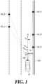
- FIG. 1 is an exemplary view showing that an apparatus for vehicle velocity correction detects a plurality of stationary targets positioned at several angles with respect to a vehicle.
- a vehicle velocity correction apparatus 100 included in a vehicle 10 senses a plurality of stationary targets 102 (102_A to 102_E) existing on a road using a first sensor (not shown).
- the first sensor may be a radar but the detailed kind of the first sensor is not limited thereto.
- the stationary target 102 may be a guar rail 104 or an object in a stop state positioned around the guard rail 104. In this case, a relative angle exists between a velocity vector of the vehicle 10 and a velocity vector of the stationary target with respect to the vehicle 10.
- FIG. 2 is an exemplary view showing the ratio of a stationary target relative velocity and a vehicle velocity that changes in accordance with a relative angle on a graph.
- Numerals of the relative velocity between the velocity vector of the vehicle 10 and a velocity vector of a stationary target are shown from -30 degrees to +30 degrees on the horizontal axis of a graph 20.
- a velocity ratio between the relative velocity of a stationary target and an ego-vehicle speed is shown from 0.9 to 1.1 with an interval of 0.02 on the vertical axis of the graph 20.
- the velocity ratio means the ratio between the relative velocity of a stationary target and an ego-vehicle speed in the present disclosure.
- a parabolic curve 200 is shown in the graph 20. The curve 200 shows the correlation between the relative velocity of a stationary target and the velocity ratio.
- graph coordinates 202 (202_A to 202_E) corresponding to stationary targets, respectively, are positioned on the curve 200.
- the vehicle velocity correction apparatus 100 can correct an ego-vehicle speed regardless of whether an error is generated in the mounting angle of the first sensor using the characteristic that the ratio of the detected relative velocity of a stationary target and an ego-vehicle speed has predetermined correlation in accordance with a relative angle.
- FIG. 3 is a block diagram for describing each component that the apparatus for vehicle velocity correction according to an embodiment of the present disclosure includes.
- the vehicle velocity correction apparatus 100 includes all or some of a calculator 300, a statistics processor 302, a vehicle velocity corrector 304, and a controller 306.
- the vehicle velocity correction apparatus 100 shown in FIG. 3 is based on an embodiment of the present disclosure. All blocks shown in FIG. 3 are not necessary components, and in another embodiment, some blocks included in the vehicle velocity correction apparatus 100 may be added, changed, or removed.
- the vehicle velocity correction apparatus 100 can perform ego-vehicle speed correction by operation of the calculator 300, the statistics processor 302, and the vehicle velocity corrector 304 except for the controller 306.
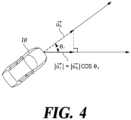
- FIG. 4 is an exemplary view showing a mathematical relationship between an ego-vehicle speed and the relative velocity of a stationary target.
- FIG. 5 is an exemplary view showing a difference of a velocity ratio according to a mounting angle of a first sensor according to an embodiment of the present disclosure and an error of a detected ego-vehicle speed detection on a graph.
- the calculator 300 calculates the relative velocity of a stationary target detected by the first sensor included in the vehicle 10, and the relative angle between the driving direction of the vehicle and the stationary target.
- the relative angle may be an angle made by a velocity vector of the vehicle and the velocity vector of the stationary target.
- the calculator 300 can calculate a velocity ratio between the relative velocity of a stationary target and an ego-vehicle speed using the relative velocity of the stationary target.
- Equation 2 the relationship of Equation 2 is formed between the relative velocity v r of a stationary target reflection signal and the ego-vehicle speed v h .
- the statistics processor 302 creates statistical data about the velocity ratio for a plurality of stationary targets on the basis of the velocity ratio between the relative velocity of a stationary target and an ego-vehicle speed detected by a second sensor (not shown) included in the vehicle 10.
- the second sensor may be a wheel velocity sensor that estimates an ego-vehicle speed on the basis of a wheel velocity, but the detailed kind of the second sensor is not limited thereto.
- the statistics processor 302 collects statistics of the correlation between the relative velocity of a stationary target and an ego-vehicle speed using the characteristic that the possibility of a stationary target existing ahead of or behind the vehicle is low.
- the statistical data created by the statistics processor 302 may be a histogram in which the velocity ratios for stationary targets are accumulated. Statistical data of a histogram type will be described below with reference to FIGS. 6 to 9 .
- Equation 3 a characteristic in which a velocity ratio changes in accordance with a mounting angle error of the first sensor and an ego-vehicle speed detection error of the second sensor is shown.
- the mounting angle error and the ego-vehicle speed detection error are as in Equation 3a and Equation 3b, respectively.
- ⁇ _error means a mounting angle error
- v h_error means an ego-vehicle speed detection error.
- Equation 3 cos ⁇ ⁇ ⁇ _ error v h _ error ⁇ cos ⁇
- the vehicle velocity corrector 304 corrects an ego-vehicle speed detected by the second sensor on the basis of a velocity ratio corresponding to the peak of statistical data.
- the vehicle velocity corrector calculates a corrected ego-vehicle speed by multiplying a reciprocal of a velocity ratio corresponding to a peak by an ego-vehicle speed detected by the second sensor.
- the peak of a statistical data expressed in a histogram type is characterized by being positioned close to 1 when an ego-vehicle speed is correct and by coming out of 1 when an ego-vehicle speed is incorrect by a second sensor error.
- the vehicle velocity corrector 304 corrects an ego-vehicle speed using the characteristic that a velocity ratio changes in accordance with an error of the second sensor.
- the calculator 300 can calculate the accumulated difference of the accumulated ego-vehicle speed correction values.
- a reference number of times of correction that is the premise of calculation of accumulated difference may be changed in various ways in accordance with embodiments of the present disclosure.
- the vehicle velocity corrector 304 determines the average of the accumulated ego-vehicle speed correction values as a final ego-vehicle speed correction value.
- a reference difference that is the premise for determining the final ego-vehicle speed correction value may be changed in various ways in accordance with embodiments of the present disclosure.
- the vehicle velocity correction apparatus 100 determines the average of the ego-vehicle speed correction values as the final ego-vehicle speed correction value. Accordingly, there is an effect that the accuracy of the ego-vehicle speed correction value determined by the vehicle velocity correction apparatus 100 is improved.
- FIG. 6 is an exemplary view showing statistical data when there is no error of a second sensor and a first sensor according to an embodiment of the present disclosure.
- a graph 60 of FIG. 6a statistical data expressed on a correlation graph 200 between a velocity ratio and a relative angle are shown. Since there is no error by the first sensor and the second sensor, most of the coordinates corresponding to a plurality of stationary targets are positioned on the curve 200.
- the vehicle velocity corrector 304 determines an ego-vehicle speed correction value by multiplying an ego-vehicle speed detected by the second sensor by 1 that is the reciprocal of the peek.
- FIG. 7 is an exemplary view showing statistical data when there is no error of the second sensor and an error by the first sensor exists.
- a graph 70 of FIG. 7a statistical data in which a difference for a correlation graph 200 between a velocity ratio and a relative angle exists are shown. Since a mounting angle error of the first sensor exists, the statistical data are biased toward the horizontal axis.
- the vehicle velocity corrector 304 determines an ego-vehicle speed correction value by multiplying an ego-vehicle speed detected by the second sensor by 1 that is the reciprocal of the peek. That is, there is an effect that the vehicle velocity correction apparatus 100 can determine an ego-vehicle speed correction value regardless of whether an error is generated in the mounting angle of the first sensor.
- FIG. 8 is an exemplary view showing statistical data when an error by the second sensor exists and there is no error of the first sensor.
- a graph 80 of FIG. 8a statistical data in which a difference exists in the vertical axis direction with respect to a correlation graph 200 between a velocity ratio and a relative angle are shown. Since an ego-vehicle speed detection error of the second sensor exists, the statistical data are biased toward the vertical axis.
- the vehicle velocity corrector 304 determines an ego-vehicle speed correction value by multiplying an ego-vehicle speed detected by the second sensor by the reciprocal of the peak 1.02.
- FIG. 9 is an exemplary view showing statistical data when errors by the second sensor and the first sensor exist.
- a graph 90 of FIG. 9a statistical data in which a difference exists in the horizontal axis direction and the vertical axis direction with respect to a correlation graph 200 between a velocity ratio and a relative angle are shown. Since an ego-vehicle speed detection error of the second sensor exists, the statistical data are biased toward the horizontal axis and the vertical axis.
- the vehicle velocity corrector 304 determines an ego-vehicle speed correction value by multiplying an ego-vehicle speed detected by the second sensor by the reciprocal of the peak 1.02. That is, comparing the embodiments of FIG. 8 and FIG. 9 , there is an effect that the vehicle velocity correction apparatus 100 can correct an ego-vehicle speed regardless of whether an error is generated in the mounting angle of the first sensor.
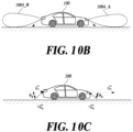
- FIG. 10 is an exemplary view showing controlling a transmission signal range of the first sensor.
- a vehicle velocity correction method based on stationary target information does not have a reference of ego-vehicle speed correction in a road environment in which a stationary target does not exist, so there is a problem that the method cannot perform ego-vehicle speed correction. Further, the vehicle velocity correction method based on stationary target information has a problem that the performance of the first sensor is deteriorated by an increase in a calculation amount in a road environment in which so many stationary targets exist.
- the vehicle velocity correction apparatus 100 can correct an ego-vehicle speed by controlling a transmission signal range of the first sensor when the number of stationary targets is less than a first reference number of article or exceeds a second reference number of article.
- the first reference number of article and/or the second reference number of article may be changed in various ways in accordance with embodiments of the present disclosure.
- the number of stationary targets is less than the first reference number of article or exceeds the second reference number of article, it may be referred to as an exceptional circumstance.
- the controller 306 transmits a control signal for controlling the range of the transmission signal that is transmitted from the first sensor to the first sensor.
- the control signal that is transmitted to the first sensor from the controller 306 may be a control signal that makes the first sensor generate an additional transmission signal of a side-lobe type toward the ground.
- the control signal may be a control signal that makes the first sensor generate a transmission signal having an expanded range toward the ground.
- a transmission signal transmitted by the first sensor in accordance with operation of the controller 306 is visually expressed.
- the controller 306 can control the first sensor to transmit a general transmission signal 1000 (1000_A and 1000_B).
- the controller 306, in this exceptional circumstance, can control the first sensor to generate an additional transmission signal 1002 (1002_A and 1002_B) of a side-lobe type toward the ground.
- a transmission signal transmitted and expanded by the first sensor in accordance with operation of the controller 306 is visually expressed.
- the controller 306 may select a control signal to transmit to the first sensor such that the first sensor transmits the transmission signal of FIG. 10a or FIG. 10b in consideration of the driving environment of the vehicle and the driving state of the vehicle.
- the calculator 300 calculates the relative angle and the relative velocity of a reflection signal reflected by the ground in response to the transmission signal generated by the first sensor in accordance with a control signal.
- the vehicle velocity corrector 304 corrects an ego-vehicle speed detected by the second sensor on the basis of the relative angle and the relative velocity.
- the driving direction velocity of the vehicle calculated by the vehicle velocity corrector 304 using a ground reflection signal is as in Equation 5.
- the vehicle velocity corrector 304 can calculate an ego-vehicle speed on the basis of the relationship of Equation 4 or Equation 5 even if the first sensor is a front-side radar or a rear-side radar. Accordingly, there is an effect that the vehicle velocity correction apparatus 100 makes it possible to correct and ego-vehicle speed even in an exceptional circumstance in which the number of stationary targets rapidly changes.
- FIG. 11 is a flowchart for describing each process included in a method of vehicle velocity correction that is performed by the apparatus for vehicle velocity correction according to an embodiment of the present disclosure.
- the vehicle velocity correction apparatus 100 calculates the relative velocity of a stationary target detected by the first sensor included in a vehicle, and the relative angle between the driving direction of the vehicle and the direction in which the stationary target is positioned (S1100).
- the vehicle velocity correction apparatus 100 creates statistical data about the velocity ratio for a plurality of stationary targets on the basis of the velocity ratio between the relative velocity of a stationary target and an ego-vehicle speed detected by a second sensor included in the vehicle (S1102).
- the statistical data may be a histogram in which the velocity ratios of stationary targets are accumulated.
- the vehicle velocity corrector 100 corrects an ego-vehicle speed detected by the second sensor on the basis of a velocity ratio corresponding to the peak of statistical data (S1104).
- the vehicle velocity corrector 100 can calculate a corrected ego-vehicle speed by multiplying the reciprocal of a velocity ratio corresponding to the peak of the statistical data by an ego-vehicle speed detected by the second sensor.
- FIG. 12 is a flowchart for describing each process included in a method of vehicle velocity correction that is performed by the apparatus for vehicle velocity correction according to an embodiment of the present disclosure and is based on accumulated differences of an ego-vehicle speed correction values.
- the vehicle velocity correction apparatus 100 detects a stationary target using the first sensor (S1200).
- the vehicle velocity correction apparatus 100 corrects an ego-vehicle speed using statistical data calculated on the basis of a plurality of stationary targets (S1202).
- the process S1202 may include the processes S1100 to S1104 of FIG. 11 .
- the vehicle velocity correction apparatus 100 calculates the accumulated difference of the accumulated ego-vehicle speed correction values (S1204, S1206).
- the vehicle velocity corrector 100 determines the average of the accumulated ego-vehicle speed correction values as a final ego-vehicle speed correction value (S1208, S1210).
- FIG. 13 is a flowchart for describing each process included in a method of vehicle velocity correction that is performed by the apparatus for vehicle velocity correction according to an embodiment of the present disclosure and is based on control of a transmission signal range.
- the vehicle velocity correction apparatus 100 transmits a control signal for controlling the range of the transmission signal that is transmitted from the first sensor to the first sensor (S1300).
- the control signal may be a control signal making the first sensor generate an additional transmission signal in a side-lobe type toward the ground or a control signal making the first sensor generate a transmission signal having an expanded range toward the ground.
- the vehicle velocity correction apparatus 100 calculates the relative angle and the relative velocity of a reflection signal reflected by the ground in response to the transmission signal generated by the first sensor in accordance with a control signal (S1302).
- the vehicle velocity corrector 100 corrects an ego-vehicle speed detected by the second sensor on the basis of the relative angle and the relative velocity of a reflection signal from the vehicle 10 (S1304).
- Various embodiments such as a device and a method described herein may be implemented by a digital electronic circuit, an integrated circuit, a field programmable gate array (FPGA), an application specific integrated circuit (ASIC), computer hardware, firmware, software, and/or a combination thereof.
- FPGA field programmable gate array
- ASIC application specific integrated circuit
- These various embodiments may include the case in which they are implemented as one or more computer programs that can be executed in a computer-programmable system.
- the programmable system includes at least one programmable processor (which may be a processor for a specific purpose or a common processor) that is connected to receive data and instructions from a storage system, at least one input device, and at least one output device and transmit data and instructions to them.
- Computer programs (which have known as programs, software, software applications, or codes) include instructions for a programmable processor and are stored in a "computer-readable recording medium".
- a computer-readable recording medium includes all kinds of recording devices that keep data that can be read by a computer system.
- the computer-readable recording medium may further include a non-volatile or non-transitory medium such as a ROM, a CD-ROM, a magnetic tape, a floppy disk, a memory card, a hard disk, a magneto-optical disc, and a storage device, or a transitory medium such as a data transmission medium.
- the computer-readable recording mediums may be distributed to computer systems that are connected through a network and may keep and execute codes that can be divisionally read by computers.
- the computer is a computer-programmable processor, a data storage system (including a volatile memory, a nonvolatile memory, or other types of storage systems, or a combination thereof), and at least one communication interface.
- the programmable computer may be one of a server, a network device, a set-top box, a built-in device, a computer expansion module, a personal computer, a laptop, a Personal Data Assistant (PDA), a cloud computing system, or a mobile device.
- PDA Personal Data Assistant
- ego-vehicle speed correction that is independent from and strong against an external environment such as an error of the physical mounting angle of a radar is performed.
- an ego-vehicle speed is corrected in real time without a delay even in an environment in which a stationary target is not detected, and an ego-vehicle speed is corrected by a constant calculation time regardless of the number of stationary targets.
Landscapes
- Engineering & Computer Science (AREA)
- Radar, Positioning & Navigation (AREA)
- Remote Sensing (AREA)
- Physics & Mathematics (AREA)
- Automation & Control Theory (AREA)
- Transportation (AREA)
- Mechanical Engineering (AREA)
- Computer Networks & Wireless Communication (AREA)
- General Physics & Mathematics (AREA)
- Mathematical Physics (AREA)
- Electromagnetism (AREA)
- Human Computer Interaction (AREA)
- Radar Systems Or Details Thereof (AREA)
Abstract
Description
- This application is based on, and claims priority from,
Korean Patent Application Number 10-2022-0068419, filed June 3, 2022 - The present disclosure relates to a method and apparatus for vehicle velocity correction.
- The following description simply provides only the background information related to the embodiment without configuring the related art.
- Recently, it is tendency that a forward collision avoidance system for safety of a driver and passengers is obligatorily mounted in vehicles under rules in global vehicle market including the U.S. The forward collision avoidance system includes sensors such as a radar, a camera, or lidar. The radar sensor of these sensors is strong against changes of the natural environment including a weather condition and an optical condition such as inclement weather, so the radar sensor is generally used for vehicles.
- The information of a target collected by a radar is expressed as relative numerals for a vehicle such as a relative velocity, a relative distance, and a relative angle. The vehicle estimates absolute numeral information of the target collected by the radar on the basis of information collected using other sensors in the vehicle such as a wheel velocity sensor and a yaw rate sensor.
- However, since the wheel velocity sensor uses a method of indirectly measuring the velocity of a vehicle, the wheel velocity sensor has an error of the sensor itself. Further, an error may be generated in wheel velocity information due to deformation and an air pressure change of a tire. Incorrect wheel velocity sensor causes a problem that the velocity of a target detected by a radar is incorrectly estimated. Accordingly, in order to accurately estimate the velocity of a target detected by a radar, there is a need for a logic that compensates for an ego-vehicle speed by itself.
- A vehicle velocity correction method of the related art compensates for an ego-vehicle speed detected by a wheel velocity sensor by detecting all stationary targets using a radar and calculating relative velocity distribution of the stationary targets.
- However, the vehicle velocity correction method of the related art does not propose a solution for the case when an error is generated in a physical mounting angle of a radar. When an error is generated in the mounting angle of a radar in the process of assembling a vehicle or an error is generated in the physical mounting angle of a radar due to a traffic accident, the relative velocity distribution of stationary targets is distorted, so there is a problem that the ego-vehicle speed correction value is incorrect.
- Further, ego-vehicle speed correction may be not operated well in a road environment in which a stationary target does not exist, and contrary, in a road environment in which a stationary target exist, a problem of performance deterioration of a radar is generated due to an increase of a calculation amount.
- According to at least one embodiment, the present disclosure provides a method for vehicle velocity correction that is performed by an apparatus for vehicle velocity correction, the method comprising: a process of calculating a relative velocity of a stationary target detected by a first sensor included in a vehicle, and a relative angle between a driving direction of the vehicle and a direction in which the stationary target is positioned; a process of creating statistical data about a relative velocity ratio for a plurality of stationary targets on the basis of the velocity ratio between a relative velocity of the stationary target and an ego-vehicle speed detected by a second sensor included in the vehicle; and a process of correcting the ego-vehicle speed detected by the second sensor on the basis of a velocity ratio corresponding to a peak on the statistical data.
- According to another embodiment, the present disclosure provides an apparatus for vehicle velocity correction, the apparatus comprising: a calculator calculating a relative velocity of a stationary target detected by a first sensor included in a vehicle, and a relative angle between a driving direction of the vehicle and a direction in which the stationary target is positioned; a statistics processor creating statistical data about a relative velocity ratio for a plurality of stationary targets on the basis of the velocity ratio between a relative velocity of the stationary target and an ego-vehicle speed detected by a second sensor included in the vehicle; and a vehicle speed corrector correcting the ego-vehicle speed detected by the second sensor on the basis of a velocity ratio corresponding to a peak on the statistical data.
- According to yet another embodiment, the present disclosure provides a vehicle including an apparatus for vehicle velocity correction.
-
-
FIG. 1 is an exemplary view showing that an apparatus for vehicle velocity correction detects a plurality of stationary targets positioned at several angles with respect to a vehicle. -
FIG. 2 is an exemplary view showing the ratio of a stationary target relative velocity and a vehicle velocity that changes in accordance with a relative angle on a graph. -
FIG. 3 is a block diagram for describing each component that the apparatus for vehicle velocity correction according to an embodiment of the present disclosure includes. -
FIG. 4 is an exemplary view showing a mathematical relationship between an ego-vehicle speed and the relative velocity of a stationary target. -
FIG. 5 is an exemplary view showing a difference of a velocity ratio according to a mounting angle of a first sensor according to an embodiment of the present disclosure and an error of a detected ego-vehicle speed detection on a graph. -
FIG. 6 is an exemplary view showing statistical data when there is no error of a second sensor and a first sensor according to an embodiment of the present disclosure. -
FIG. 7 is an exemplary view showing statistical data when there is no error of the second sensor and an error by the first sensor exists. -
FIG. 8 is an exemplary view showing statistical data when an error by the second sensor exists and there is no error of the first sensor. -
FIG. 9 is an exemplary view showing statistical data when errors by the second sensor and the first sensor exist. -
FIG. 10 is an exemplary view showing controlling a transmission signal range of the first sensor. -
FIG. 11 is a flowchart for describing each process included in a method of vehicle velocity correction that is performed by the apparatus for vehicle velocity correction according to an embodiment of the present disclosure. -
FIG. 12 is a flowchart for describing each process included in a method of vehicle velocity correction that is performed by the apparatus for vehicle velocity correction according to an embodiment of the present disclosure and is based on accumulated differences of an ego-vehicle speed correction values. -
FIG. 13 is a flowchart for describing each process included in a method of vehicle velocity correction that is performed by the apparatus for vehicle velocity correction according to an embodiment of the present disclosure and is based on control of a transmission signal range. - An apparatus for vehicle velocity correction according to an embodiment can prevent distortion of ego-vehicle speed correction information when an error is generated in the physical mounting angle of a radar.
- An apparatus for vehicle velocity correction according to another embodiment can correct an ego-vehicle speed even if ego-vehicle speed correction based on stationary target information is difficult in a road environment in which a stationary target does not exist.
- An apparatus for vehicle velocity correction according to another embodiment can correct an ego-vehicle speed even without increasing the calculation amount of a radar in a road environment in which so many stationary targets exist.
- Hereinafter, some embodiments of the present disclosure will be described in detail with reference to the accompanying drawings. In the following description, like reference numerals preferably designate like elements, although the elements are shown in different drawings. Further, in the following description of some embodiments, a detailed description of related known components and functions when considered to obscure the subject of the present disclosure will be omitted for the purpose of clarity and for brevity.
- In describing the components of the embodiments, alphanumeric codes may be used such as first, second, i), ii), a), b), etc., solely for the purpose of differentiating one component from others but not to imply or suggest the substances, the order, or sequence of the components. Throughout this specification, when parts "include" or "comprise" a component, they are meant to further include other components, not to exclude thereof unless there is a particular description contrary thereto.
- The description of the present disclosure to follow in conjunction with the accompanying drawings is intended to describe exemplary embodiments of the present disclosure and is not intended to represent the only embodiments in which the technical idea of the present disclosure may be practiced.
-
FIG. 1 is an exemplary view showing that an apparatus for vehicle velocity correction detects a plurality of stationary targets positioned at several angles with respect to a vehicle. - A vehicle
velocity correction apparatus 100 included in avehicle 10 senses a plurality of stationary targets 102 (102_A to 102_E) existing on a road using a first sensor (not shown). In this case, the first sensor may be a radar but the detailed kind of the first sensor is not limited thereto. Thestationary target 102 may be aguar rail 104 or an object in a stop state positioned around theguard rail 104. In this case, a relative angle exists between a velocity vector of thevehicle 10 and a velocity vector of the stationary target with respect to thevehicle 10. -
FIG. 2 is an exemplary view showing the ratio of a stationary target relative velocity and a vehicle velocity that changes in accordance with a relative angle on a graph. - Numerals of the relative velocity between the velocity vector of the
vehicle 10 and a velocity vector of a stationary target are shown from -30 degrees to +30 degrees on the horizontal axis of agraph 20. A velocity ratio between the relative velocity of a stationary target and an ego-vehicle speed is shown from 0.9 to 1.1 with an interval of 0.02 on the vertical axis of thegraph 20. The velocity ratio means the ratio between the relative velocity of a stationary target and an ego-vehicle speed in the present disclosure. Aparabolic curve 200 is shown in thegraph 20. Thecurve 200 shows the correlation between the relative velocity of a stationary target and the velocity ratio. When there is no error in a mounting angle of a first sensor, graph coordinates 202 (202_A to 202_E) corresponding to stationary targets, respectively, are positioned on thecurve 200. The vehiclevelocity correction apparatus 100 according to an embodiment of the present disclosure can correct an ego-vehicle speed regardless of whether an error is generated in the mounting angle of the first sensor using the characteristic that the ratio of the detected relative velocity of a stationary target and an ego-vehicle speed has predetermined correlation in accordance with a relative angle. -
FIG. 3 is a block diagram for describing each component that the apparatus for vehicle velocity correction according to an embodiment of the present disclosure includes. - The vehicle
velocity correction apparatus 100 according to an embodiment of the present disclosure includes all or some of acalculator 300, astatistics processor 302, avehicle velocity corrector 304, and acontroller 306. The vehiclevelocity correction apparatus 100 shown inFIG. 3 is based on an embodiment of the present disclosure. All blocks shown inFIG. 3 are not necessary components, and in another embodiment, some blocks included in the vehiclevelocity correction apparatus 100 may be added, changed, or removed. For example, the vehiclevelocity correction apparatus 100 can perform ego-vehicle speed correction by operation of thecalculator 300, thestatistics processor 302, and thevehicle velocity corrector 304 except for thecontroller 306. -
FIG. 4 is an exemplary view showing a mathematical relationship between an ego-vehicle speed and the relative velocity of a stationary target. -
FIG. 5 is an exemplary view showing a difference of a velocity ratio according to a mounting angle of a first sensor according to an embodiment of the present disclosure and an error of a detected ego-vehicle speed detection on a graph. - Hereafter, each of components included in the vehicle
velocity correction apparatus 100 is described with reference toFIGS. 3 to 5 . - The
calculator 300 calculates the relative velocity of a stationary target detected by the first sensor included in thevehicle 10, and the relative angle between the driving direction of the vehicle and the stationary target. In this case, the relative angle may be an angle made by a velocity vector of the vehicle and the velocity vector of the stationary target. Thecalculator 300 can calculate a velocity ratio between the relative velocity of a stationary target and an ego-vehicle speed using the relative velocity of the stationary target. - Referring to
FIG. 4 , the relative velocity vr of a stationary target detected from a signal reflected by the stationary target is projection of the driving direction velocity of the vehicle vh with respect to the relative angle θ of the stationary target. That is, when the first sensor is a front radar, the relationship ofEquation 1 is formed between the relative velocity vr of a stationary target reflection signal and the ego-vehicle speed vh .
[Equation 1]

- Meanwhile, when the first sensor is a rear radar, the relationship of
Equation 2 is formed between the relative velocity vr of a stationary target reflection signal and the ego-vehicle speed vh .
[Equation 2]

- The
statistics processor 302 creates statistical data about the velocity ratio for a plurality of stationary targets on the basis of the velocity ratio between the relative velocity of a stationary target and an ego-vehicle speed detected by a second sensor (not shown) included in thevehicle 10. The second sensor may be a wheel velocity sensor that estimates an ego-vehicle speed on the basis of a wheel velocity, but the detailed kind of the second sensor is not limited thereto. Thestatistics processor 302 collects statistics of the correlation between the relative velocity of a stationary target and an ego-vehicle speed using the characteristic that the possibility of a stationary target existing ahead of or behind the vehicle is low. In this case, the statistical data created by thestatistics processor 302 may be a histogram in which the velocity ratios for stationary targets are accumulated. Statistical data of a histogram type will be described below with reference toFIGS. 6 to 9 . - Referring to
FIG. 5 , a characteristic in which a velocity ratio changes in accordance with a mounting angle error of the first sensor and an ego-vehicle speed detection error of the second sensor is shown. The mounting angle error and the ego-vehicle speed detection error are as in Equation 3a and Equation 3b, respectively. In this case, θ_error means a mounting angle error and vh_error means an ego-vehicle speed detection error.
[Equation 3]

- The
vehicle velocity corrector 304 corrects an ego-vehicle speed detected by the second sensor on the basis of a velocity ratio corresponding to the peak of statistical data. In detail, the vehicle velocity corrector calculates a corrected ego-vehicle speed by multiplying a reciprocal of a velocity ratio corresponding to a peak by an ego-vehicle speed detected by the second sensor. The peak of a statistical data expressed in a histogram type is characterized by being positioned close to 1 when an ego-vehicle speed is correct and by coming out of 1 when an ego-vehicle speed is incorrect by a second sensor error. Thevehicle velocity corrector 304 corrects an ego-vehicle speed using the characteristic that a velocity ratio changes in accordance with an error of the second sensor. - Meanwhile, when ego-vehicle speed correction values are calculated over a predetermined number of times of correction, the
calculator 300 can calculate the accumulated difference of the accumulated ego-vehicle speed correction values. A reference number of times of correction that is the premise of calculation of accumulated difference may be changed in various ways in accordance with embodiments of the present disclosure. - When the calculated accumulated difference is less than a preset reference difference, the
vehicle velocity corrector 304 determines the average of the accumulated ego-vehicle speed correction values as a final ego-vehicle speed correction value. A reference difference that is the premise for determining the final ego-vehicle speed correction value may be changed in various ways in accordance with embodiments of the present disclosure. When a plurality of ego-vehicle speed correction values with a small difference is accumulated, the vehiclevelocity correction apparatus 100 determines the average of the ego-vehicle speed correction values as the final ego-vehicle speed correction value. Accordingly, there is an effect that the accuracy of the ego-vehicle speed correction value determined by the vehiclevelocity correction apparatus 100 is improved. -
FIG. 6 is an exemplary view showing statistical data when there is no error of a second sensor and a first sensor according to an embodiment of the present disclosure. - Referring to a
graph 60 ofFIG. 6a , statistical data expressed on acorrelation graph 200 between a velocity ratio and a relative angle are shown. Since there is no error by the first sensor and the second sensor, most of the coordinates corresponding to a plurality of stationary targets are positioned on thecurve 200. - Referring to
statistical data 61 expressed in a histogram type ofFIG. 6b , the peak of the vehicle velocity ratio is formed around 1. Accordingly, thevehicle velocity corrector 304 determines an ego-vehicle speed correction value by multiplying an ego-vehicle speed detected by the second sensor by 1 that is the reciprocal of the peek. -
FIG. 7 is an exemplary view showing statistical data when there is no error of the second sensor and an error by the first sensor exists. - Referring to a
graph 70 ofFIG. 7a , statistical data in which a difference for acorrelation graph 200 between a velocity ratio and a relative angle exists are shown. Since a mounting angle error of the first sensor exists, the statistical data are biased toward the horizontal axis. - However, referring to
statistical data 71 expressed in a histogram type ofFIG. 7b , the peak of the vehicle velocity ratio is formed around 1. Accordingly, thevehicle velocity corrector 304 determines an ego-vehicle speed correction value by multiplying an ego-vehicle speed detected by the second sensor by 1 that is the reciprocal of the peek. That is, there is an effect that the vehiclevelocity correction apparatus 100 can determine an ego-vehicle speed correction value regardless of whether an error is generated in the mounting angle of the first sensor. -
FIG. 8 is an exemplary view showing statistical data when an error by the second sensor exists and there is no error of the first sensor. - Referring to a
graph 80 ofFIG. 8a , statistical data in which a difference exists in the vertical axis direction with respect to acorrelation graph 200 between a velocity ratio and a relative angle are shown. Since an ego-vehicle speed detection error of the second sensor exists, the statistical data are biased toward the vertical axis. - Referring to
statistical data 81 expressed in a histogram type ofFIG. 8b , the peak of the vehicle velocity ratio is formed around 1.02. Accordingly, thevehicle velocity corrector 304 determines an ego-vehicle speed correction value by multiplying an ego-vehicle speed detected by the second sensor by the reciprocal of the peak 1.02. -
FIG. 9 is an exemplary view showing statistical data when errors by the second sensor and the first sensor exist. - Referring to a
graph 90 ofFIG. 9a , statistical data in which a difference exists in the horizontal axis direction and the vertical axis direction with respect to acorrelation graph 200 between a velocity ratio and a relative angle are shown. Since an ego-vehicle speed detection error of the second sensor exists, the statistical data are biased toward the horizontal axis and the vertical axis. - Referring to
statistical data 91 expressed in a histogram type ofFIG. 9b , the peak of the vehicle velocity ratio is formed around 1.02. Accordingly, thevehicle velocity corrector 304 determines an ego-vehicle speed correction value by multiplying an ego-vehicle speed detected by the second sensor by the reciprocal of the peak 1.02. That is, comparing the embodiments ofFIG. 8 andFIG. 9 , there is an effect that the vehiclevelocity correction apparatus 100 can correct an ego-vehicle speed regardless of whether an error is generated in the mounting angle of the first sensor. -
FIG. 10 is an exemplary view showing controlling a transmission signal range of the first sensor. - A vehicle velocity correction method based on stationary target information does not have a reference of ego-vehicle speed correction in a road environment in which a stationary target does not exist, so there is a problem that the method cannot perform ego-vehicle speed correction. Further, the vehicle velocity correction method based on stationary target information has a problem that the performance of the first sensor is deteriorated by an increase in a calculation amount in a road environment in which so many stationary targets exist.
- The vehicle
velocity correction apparatus 100 can correct an ego-vehicle speed by controlling a transmission signal range of the first sensor when the number of stationary targets is less than a first reference number of article or exceeds a second reference number of article. In this case, the first reference number of article and/or the second reference number of article may be changed in various ways in accordance with embodiments of the present disclosure. When the number of stationary targets is less than the first reference number of article or exceeds the second reference number of article, it may be referred to as an exceptional circumstance. - The
controller 306 transmits a control signal for controlling the range of the transmission signal that is transmitted from the first sensor to the first sensor. In this case, the control signal that is transmitted to the first sensor from thecontroller 306 may be a control signal that makes the first sensor generate an additional transmission signal of a side-lobe type toward the ground. In another embodiment, the control signal may be a control signal that makes the first sensor generate a transmission signal having an expanded range toward the ground. - Referring to
FIG. 10a , a transmission signal transmitted by the first sensor in accordance with operation of thecontroller 306 is visually expressed. When stationary targets exist by the first reference number or article or more and less than the second reference number or article, thecontroller 306 can control the first sensor to transmit a general transmission signal 1000 (1000_A and 1000_B). Thecontroller 306, in this exceptional circumstance, can control the first sensor to generate an additional transmission signal 1002 (1002_A and 1002_B) of a side-lobe type toward the ground. - Referring to
FIG. 10B , a transmission signal transmitted and expanded by the first sensor in accordance with operation of thecontroller 306 is visually expressed. Thecontroller 306, in this exceptional circumstance, can control the first sensor to generate an expanded transmission signal 1004 (1004_A and 1004_B) toward the ground. Thecontroller 306 may select a control signal to transmit to the first sensor such that the first sensor transmits the transmission signal ofFIG. 10a orFIG. 10b in consideration of the driving environment of the vehicle and the driving state of the vehicle. - The
calculator 300 calculates the relative angle and the relative velocity of a reflection signal reflected by the ground in response to the transmission signal generated by the first sensor in accordance with a control signal. - The
vehicle velocity corrector 304 corrects an ego-vehicle speed detected by the second sensor on the basis of the relative angle and the relative velocity. Referring toFIG. 10c , the relative velocity vg of the signal reflected by the ground is the same as the scalar product of the relative angle θg of the reflection signal and a vehicle driving direction velocity vh. That is, when the first sensor is a front radar, the driving direction velocity of the vehicle calculated by thevehicle velocity corrector 304 using a ground reflection signal is as inEquation 4.
[Equation 4]

- Meanwhile, when the first sensor is a front radar, the driving direction velocity of the vehicle calculated by the
vehicle velocity corrector 304 using a ground reflection signal is as inEquation 5. Thevehicle velocity corrector 304 can calculate an ego-vehicle speed on the basis of the relationship ofEquation 4 orEquation 5 even if the first sensor is a front-side radar or a rear-side radar. Accordingly, there is an effect that the vehiclevelocity correction apparatus 100 makes it possible to correct and ego-vehicle speed even in an exceptional circumstance in which the number of stationary targets rapidly changes.
[Equation 5]

-
FIG. 11 is a flowchart for describing each process included in a method of vehicle velocity correction that is performed by the apparatus for vehicle velocity correction according to an embodiment of the present disclosure. - The vehicle
velocity correction apparatus 100 calculates the relative velocity of a stationary target detected by the first sensor included in a vehicle, and the relative angle between the driving direction of the vehicle and the direction in which the stationary target is positioned (S1100). - The vehicle
velocity correction apparatus 100 creates statistical data about the velocity ratio for a plurality of stationary targets on the basis of the velocity ratio between the relative velocity of a stationary target and an ego-vehicle speed detected by a second sensor included in the vehicle (S1102). In this case, the statistical data may be a histogram in which the velocity ratios of stationary targets are accumulated. - The
vehicle velocity corrector 100 corrects an ego-vehicle speed detected by the second sensor on the basis of a velocity ratio corresponding to the peak of statistical data (S1104). Thevehicle velocity corrector 100 can calculate a corrected ego-vehicle speed by multiplying the reciprocal of a velocity ratio corresponding to the peak of the statistical data by an ego-vehicle speed detected by the second sensor. -
FIG. 12 is a flowchart for describing each process included in a method of vehicle velocity correction that is performed by the apparatus for vehicle velocity correction according to an embodiment of the present disclosure and is based on accumulated differences of an ego-vehicle speed correction values. - The vehicle
velocity correction apparatus 100 detects a stationary target using the first sensor (S1200). - The vehicle
velocity correction apparatus 100 corrects an ego-vehicle speed using statistical data calculated on the basis of a plurality of stationary targets (S1202). In this case, the process S1202 may include the processes S1100 to S1104 ofFIG. 11 . - When ego-vehicle speed correction value are calculated over a predetermined number of times of correction, the vehicle
velocity correction apparatus 100 calculates the accumulated difference of the accumulated ego-vehicle speed correction values (S1204, S1206). - When the calculated accumulated difference is less than a preset reference difference, the
vehicle velocity corrector 100 determines the average of the accumulated ego-vehicle speed correction values as a final ego-vehicle speed correction value (S1208, S1210). -
FIG. 13 is a flowchart for describing each process included in a method of vehicle velocity correction that is performed by the apparatus for vehicle velocity correction according to an embodiment of the present disclosure and is based on control of a transmission signal range. - The vehicle
velocity correction apparatus 100 transmits a control signal for controlling the range of the transmission signal that is transmitted from the first sensor to the first sensor (S1300). In this case, the control signal may be a control signal making the first sensor generate an additional transmission signal in a side-lobe type toward the ground or a control signal making the first sensor generate a transmission signal having an expanded range toward the ground. - The vehicle
velocity correction apparatus 100 calculates the relative angle and the relative velocity of a reflection signal reflected by the ground in response to the transmission signal generated by the first sensor in accordance with a control signal (S1302). - The
vehicle velocity corrector 100 corrects an ego-vehicle speed detected by the second sensor on the basis of the relative angle and the relative velocity of a reflection signal from the vehicle 10 (S1304). - The flowcharts are described to sequentially perform the processes in the specification, but these are provided only to exemplarily describe the spirit of some embodiments of the present disclosure. In other words, the present disclosure may be changed and modified in various ways by those skilled in the art including some embodiments of the present disclosure by changing the processes described in the flowcharts of the present disclosure or performing one or more of the processes in parallel without departing from the fundamental characteristics of some embodiments of the present disclosure, so the flowcharts of the present disclosure are not limited to a time-series sequence.
- Various embodiments such as a device and a method described herein may be implemented by a digital electronic circuit, an integrated circuit, a field programmable gate array (FPGA), an application specific integrated circuit (ASIC), computer hardware, firmware, software, and/or a combination thereof. These various embodiments may include the case in which they are implemented as one or more computer programs that can be executed in a computer-programmable system. The programmable system includes at least one programmable processor (which may be a processor for a specific purpose or a common processor) that is connected to receive data and instructions from a storage system, at least one input device, and at least one output device and transmit data and instructions to them. Computer programs (which have known as programs, software, software applications, or codes) include instructions for a programmable processor and are stored in a "computer-readable recording medium".
- A computer-readable recording medium includes all kinds of recording devices that keep data that can be read by a computer system. The computer-readable recording medium may further include a non-volatile or non-transitory medium such as a ROM, a CD-ROM, a magnetic tape, a floppy disk, a memory card, a hard disk, a magneto-optical disc, and a storage device, or a transitory medium such as a data transmission medium. Further, the computer-readable recording mediums may be distributed to computer systems that are connected through a network and may keep and execute codes that can be divisionally read by computers.
- Various embodiments of apparatuses and methods described herein may be implemented by a programmable computer. The computer is a computer-programmable processor, a data storage system (including a volatile memory, a nonvolatile memory, or other types of storage systems, or a combination thereof), and at least one communication interface. For example, the programmable computer may be one of a server, a network device, a set-top box, a built-in device, a computer expansion module, a personal computer, a laptop, a Personal Data Assistant (PDA), a cloud computing system, or a mobile device.
- According to an embodiment, there is an effect that ego-vehicle speed correction that is independent from and strong against an external environment such as an error of the physical mounting angle of a radar is performed.
- According to another embodiment, there is an effect that an ego-vehicle speed is corrected in real time without a delay even in an environment in which a stationary target is not detected, and an ego-vehicle speed is corrected by a constant calculation time regardless of the number of stationary targets.
- Although exemplary embodiments of the present disclosure have been described for illustrative purposes, those skilled in the art will appreciate that various modifications, additions, and substitutions are possible, without departing from the idea and scope of the claimed invention. Therefore, exemplary embodiments of the present disclosure have been described for the sake of brevity and clarity. The scope of the technical idea of the embodiments of the present disclosure is not limited by the illustrations. Accordingly, one of ordinary skill would understand the scope of the claimed invention is not to be limited by the above explicitly described embodiments but by the claims and equivalents thereof.
Claims (15)
- A method for vehicle velocity correction that is performed by an apparatus for vehicle velocity correction, the method comprising:a process of calculating a relative velocity of a stationary target detected by a first sensor included in a vehicle, and a relative angle between a driving direction of the vehicle and a direction in which the stationary target is positioned;a process of creating statistical data about a relative velocity ratio for a plurality of stationary targets based on the relative velocity ratio between a relative velocity of the stationary target and an ego-vehicle speed detected by a second sensor included in the vehicle; anda process of correcting the ego-vehicle speed detected by the second sensor based on a velocity ratio corresponding to a peak on the statistical data.
- The method of claim 1, wherein the statistical data are a histogram in which velocity ratios of stationary targets are accumulated in the process of creating.
- The method of claim 1 or 2, wherein the process of correcting includes a process of calculating a corrected ego-vehicle speed by multiplying a reciprocal of the velocity ratio corresponding to the peak by the ego-vehicle speed detected by the second sensor.
- The method of any one of claims 1 to 3, further comprising:a process of calculating an accumulated difference of accumulated ego-vehicle speed correction values when ego-vehicle speed correction values are accumulated by a preset number of times of correction or more; anda process of determining an average of the accumulated ego-vehicle speed correction values as a final accumulated ego-vehicle speed correction value when the calculated accumulated difference is less than a preset reference difference.
- The method of any one of claims 1 to 4, further comprisinga process of transmitting a control signal for controlling a range of a transmission signal, which is transmitted from the first sensor, to the first sensor;a process of calculating a relative angle and a relative velocity of a reflection signal reflected by a ground in response to the transmission signal generated by the first sensor in accordance with the control signal; anda process of correcting the ego-vehicle speed detected by the second sensor based on the relative angle and the relative velocity.
- The method of claim 5, wherein in the process of transmitting a control signal to the first sensor, the control signal is a control signal making the first sensor generate an additional transmission signal in a side-lobe type toward the ground or a control signal making the first sensor generate a transmission signal having an expanded range toward the ground.
- An apparatus for vehicle velocity correction, the apparatus comprising:a calculator calculating a relative velocity of a stationary target detected by a first sensor included in a vehicle, and a relative angle between a driving direction of the vehicle and a direction in which the stationary target is positioned;a statistics processor creating statistical data about a relative velocity ratio for a plurality of stationary targets based on the relative velocity ratio between a relative velocity of the stationary target and an ego-vehicle speed detected by a second sensor included in the vehicle; anda vehicle speed corrector correcting the ego-vehicle speed detected by the second sensor based on a velocity ratio corresponding to a peak on the statistical data.
- The apparatus of claim 7, wherein the statistical data created by the statistics processor are a histogram in which velocity ratios of stationary targets are accumulated.
- The apparatus of claim 7 or 8, wherein the vehicle speed corrector calculates a corrected ego-vehicle speed by multiplying a reciprocal of the velocity ratio corresponding to the peak by the ego-vehicle speed detected by the second sensor.
- The apparatus of any one of claims 7 to 9, wherein the calculator calculates an accumulated difference of accumulated ego-vehicle speed correction values when ego-vehicle speed correction values are accumulated by a preset number of times of correction or more, and
the vehicle speed corrector determines an average of the accumulated ego-vehicle speed correction values as a final accumulated ego-vehicle speed correction value when the calculated accumulated difference is less than a preset reference difference. - The apparatus of any one of claims 7 to 10, further comprisinga controller transmitting a control signal for controlling a range of a transmission signal, which is transmitted from the first sensor, to the first sensor,wherein the calculator calculates a relative angle and a relative velocity of a reflection signal reflected by a ground in response to the transmission signal generated by the first sensor in accordance with the control signal, andthe vehicle speed corrector corrects the ego-vehicle speed detected by the second sensor based on the relative angle and the relative velocity.
- The apparatus of claim 11, wherein the control signal that is transmitted by the controller is a control signal making the first sensor generate an additional transmission signal in a side-lobe type toward the ground or a control signal making the first sensor generate a transmission signal having an expanded range toward the ground.
- A vehicle comprising: an apparatus for vehicle velocity correction, the apparatus for vehicle velocity correction comprising:a calculator calculating a relative velocity of a stationary target detected by a first sensor included in a vehicle, and a relative angle between a driving direction of the vehicle and a direction in which the stationary target is positioned;
a statistics processor creating statistical data about a relative velocity ratio for a plurality of stationary targets based on the velocity ratio between a relative velocity of the stationary target and an ego-vehicle speed detected by a second sensor included in the vehicle; anda vehicle speed corrector correcting the ego-vehicle speed detected by the second sensor based on a velocity ratio corresponding to a peak on the statistical data. - The vehicle of claim 13, wherein:the calculator calculates an accumulated difference of accumulated ego-vehicle speed correction values when ego-vehicle speed correction values are accumulated by a preset number of times of correction or more, andthe vehicle speed corrector determines an average of the accumulated ego-vehicle speed correction values as a final accumulated ego-vehicle speed correction value when the calculated accumulated difference is less than a preset reference difference.
- The vehicle of claim 13 or 14, wherein the apparatus for vechicle velocity correction further comprises:a controller transmitting a control signal for controlling a range of a transmission signal, which is transmitted from the first sensor, to the first sensor,wherein the calculator calculates a relative angle and a relative velocity of a reflection signal reflected by a ground in response to the transmission signal generated by the first sensor in accordance with the control signal, andthe vehicle speed corrector corrects the ego-vehicle speed detected by the second sensor based on the relative angle and the relative velocity.
Applications Claiming Priority (1)
| Application Number | Priority Date | Filing Date | Title |
|---|---|---|---|
| KR1020220068419A KR102662608B1 (en) | 2022-06-03 | 2022-06-03 | Method And Apparatus for Vehicle Speed Correction |
Publications (2)
| Publication Number | Publication Date |
|---|---|
| EP4286891A1 true EP4286891A1 (en) | 2023-12-06 |
| EP4286891B1 EP4286891B1 (en) | 2025-08-27 |
Family
ID=84604205
Family Applications (1)
| Application Number | Title | Priority Date | Filing Date |
|---|---|---|---|
| EP22216000.4A Active EP4286891B1 (en) | 2022-06-03 | 2022-12-22 | Method and apparatus for vehicle speed correction |
Country Status (4)
| Country | Link |
|---|---|
| US (1) | US20230391348A1 (en) |
| EP (1) | EP4286891B1 (en) |
| KR (1) | KR102662608B1 (en) |
| CN (1) | CN117163041A (en) |
Citations (4)
| Publication number | Priority date | Publication date | Assignee | Title |
|---|---|---|---|---|
| JP2000081480A (en) * | 1998-09-07 | 2000-03-21 | Denso Corp | FMCW radar device, recording medium, and vehicle control device |
| JP2002062352A (en) * | 2000-08-24 | 2002-02-28 | Hitachi Ltd | Automotive radar equipment |
| US20150369912A1 (en) * | 2013-09-12 | 2015-12-24 | Panasonic Corporation | Radar device, vehicle, and moving object speed detection method |
| US20180203109A1 (en) * | 2017-01-17 | 2018-07-19 | Denso Ten Limited | Radar device and vehicle velocity correction method |
Family Cites Families (3)
| Publication number | Priority date | Publication date | Assignee | Title |
|---|---|---|---|---|
| JP3633744B2 (en) * | 1997-03-17 | 2005-03-30 | 三菱自動車工業株式会社 | Vehicle travel control device |
| JP2022037373A (en) * | 2020-08-25 | 2022-03-09 | ソニーセミコンダクタソリューションズ株式会社 | Information processor and method for processing information |
| KR20220056299A (en) * | 2020-10-27 | 2022-05-06 | 현대모비스 주식회사 | Radar control system and method of vehicle |
-
2022
- 2022-06-03 KR KR1020220068419A patent/KR102662608B1/en active Active
- 2022-11-21 US US17/991,186 patent/US20230391348A1/en active Pending
- 2022-12-22 EP EP22216000.4A patent/EP4286891B1/en active Active
- 2022-12-28 CN CN202211698462.6A patent/CN117163041A/en active Pending
Patent Citations (4)
| Publication number | Priority date | Publication date | Assignee | Title |
|---|---|---|---|---|
| JP2000081480A (en) * | 1998-09-07 | 2000-03-21 | Denso Corp | FMCW radar device, recording medium, and vehicle control device |
| JP2002062352A (en) * | 2000-08-24 | 2002-02-28 | Hitachi Ltd | Automotive radar equipment |
| US20150369912A1 (en) * | 2013-09-12 | 2015-12-24 | Panasonic Corporation | Radar device, vehicle, and moving object speed detection method |
| US20180203109A1 (en) * | 2017-01-17 | 2018-07-19 | Denso Ten Limited | Radar device and vehicle velocity correction method |
Also Published As
| Publication number | Publication date |
|---|---|
| KR20230168017A (en) | 2023-12-12 |
| US20230391348A1 (en) | 2023-12-07 |
| KR102662608B1 (en) | 2024-04-30 |
| EP4286891B1 (en) | 2025-08-27 |
| CN117163041A (en) | 2023-12-05 |
Similar Documents
| Publication | Publication Date | Title |
|---|---|---|
| US10634793B1 (en) | Lidar detection device of detecting close-distance obstacle and method thereof | |
| US11772652B2 (en) | Cooperative adaptive cruise control system based on driving pattern of target vehicle | |
| EP3342668B1 (en) | Cooperative adaptive cruise control system based on driving pattern of target vehicle | |
| US9824586B2 (en) | Moving object recognition systems, moving object recognition programs, and moving object recognition methods | |
| US8452535B2 (en) | Systems and methods for precise sub-lane vehicle positioning | |
| KR102569900B1 (en) | Apparatus and method for performing omnidirectional sensor-fusion and vehicle including the same | |
| US11565751B2 (en) | Lane separation line detection correcting device, lane separation line detection correcting method, and automatic driving system | |
| US10821975B2 (en) | Lane division line recognition apparatus, lane division line recognition method, driving assist apparatus including lane division line recognition apparatus, and driving assist method including lane division line recognition method | |
| US20130335569A1 (en) | Vehicle with improved traffic-object position detection | |
| KR101468963B1 (en) | Apparatus and Method for compensating installment angle of multi radar for vehicle | |
| US10579888B2 (en) | Method and system for improving object detection and object classification | |
| US11458966B2 (en) | Method and device of determining kinematics of a target | |
| US11307292B2 (en) | ODM information reliability determination system and method and vehicle using the same | |
| EP4286891A1 (en) | Method and apparatus for vehicle speed correction | |
| US20200062252A1 (en) | Method and apparatus for diagonal lane detection | |
| KR20240033471A (en) | Method and system for sensor fusion in vehicle | |
| KR20150134063A (en) | System and method for removing mirror track in tunnel for automotive radar Smart Cruise Control | |
| US20210139030A1 (en) | Apparatus and Method of Identifying Short Cut-In Target | |
| EP4187279A1 (en) | Method and apparatus for tracking road facility based on vehicle motion characteristics | |
| US12270908B2 (en) | Virtual beams for identification of edge and planar points in lidar point cloud obtained with vehicle lidar system | |
| KR102660192B1 (en) | Lane Departure Prevention Apparatus | |
| JP2021012086A (en) | Lane estimation apparatus | |
| JP7412254B2 (en) | Object recognition device and object recognition method | |
| US12248058B2 (en) | Track association based on azimuth extension and compactness errors | |
| KR102780578B1 (en) | System and method for estimating shape of object based on multi-radar sensor fusion |
Legal Events
| Date | Code | Title | Description |
|---|---|---|---|
| PUAI | Public reference made under article 153(3) epc to a published international application that has entered the european phase |
Free format text: ORIGINAL CODE: 0009012 |
|
| STAA | Information on the status of an ep patent application or granted ep patent |
Free format text: STATUS: REQUEST FOR EXAMINATION WAS MADE |
|
| 17P | Request for examination filed |
Effective date: 20221222 |
|
| AK | Designated contracting states |
Kind code of ref document: A1 Designated state(s): AL AT BE BG CH CY CZ DE DK EE ES FI FR GB GR HR HU IE IS IT LI LT LU LV MC ME MK MT NL NO PL PT RO RS SE SI SK SM TR |
|
| STAA | Information on the status of an ep patent application or granted ep patent |
Free format text: STATUS: EXAMINATION IS IN PROGRESS |
|
| 17Q | First examination report despatched |
Effective date: 20240722 |
|
| GRAP | Despatch of communication of intention to grant a patent |
Free format text: ORIGINAL CODE: EPIDOSNIGR1 |
|
| STAA | Information on the status of an ep patent application or granted ep patent |
Free format text: STATUS: GRANT OF PATENT IS INTENDED |
|
| INTG | Intention to grant announced |
Effective date: 20250403 |
|
| GRAS | Grant fee paid |
Free format text: ORIGINAL CODE: EPIDOSNIGR3 |
|
| GRAA | (expected) grant |
Free format text: ORIGINAL CODE: 0009210 |
|
| STAA | Information on the status of an ep patent application or granted ep patent |
Free format text: STATUS: THE PATENT HAS BEEN GRANTED |
|
| P01 | Opt-out of the competence of the unified patent court (upc) registered |
Free format text: CASE NUMBER: APP_30582/2025 Effective date: 20250626 |
|
| AK | Designated contracting states |
Kind code of ref document: B1 Designated state(s): AL AT BE BG CH CY CZ DE DK EE ES FI FR GB GR HR HU IE IS IT LI LT LU LV MC ME MK MT NL NO PL PT RO RS SE SI SK SM TR |
|
| REG | Reference to a national code |
Ref country code: CH Ref legal event code: EP |
|
| REG | Reference to a national code |
Ref country code: DE Ref legal event code: R096 Ref document number: 602022020178 Country of ref document: DE |
|
| REG | Reference to a national code |
Ref country code: IE Ref legal event code: FG4D |
|
| REG | Reference to a national code |
Ref country code: NL Ref legal event code: MP Effective date: 20250827 |
|
| PG25 | Lapsed in a contracting state [announced via postgrant information from national office to epo] |
Ref country code: IS Free format text: LAPSE BECAUSE OF FAILURE TO SUBMIT A TRANSLATION OF THE DESCRIPTION OR TO PAY THE FEE WITHIN THE PRESCRIBED TIME-LIMIT Effective date: 20251227 |
|
| PGFP | Annual fee paid to national office [announced via postgrant information from national office to epo] |
Ref country code: DE Payment date: 20251120 Year of fee payment: 4 |
|
| PG25 | Lapsed in a contracting state [announced via postgrant information from national office to epo] |
Ref country code: NO Free format text: LAPSE BECAUSE OF FAILURE TO SUBMIT A TRANSLATION OF THE DESCRIPTION OR TO PAY THE FEE WITHIN THE PRESCRIBED TIME-LIMIT Effective date: 20251127 |
|
| REG | Reference to a national code |
Ref country code: LT Ref legal event code: MG9D |
|
| PG25 | Lapsed in a contracting state [announced via postgrant information from national office to epo] |
Ref country code: PT Free format text: LAPSE BECAUSE OF FAILURE TO SUBMIT A TRANSLATION OF THE DESCRIPTION OR TO PAY THE FEE WITHIN THE PRESCRIBED TIME-LIMIT Effective date: 20251229 |
|
| PG25 | Lapsed in a contracting state [announced via postgrant information from national office to epo] |
Ref country code: FI Free format text: LAPSE BECAUSE OF FAILURE TO SUBMIT A TRANSLATION OF THE DESCRIPTION OR TO PAY THE FEE WITHIN THE PRESCRIBED TIME-LIMIT Effective date: 20250827 |
|
| PG25 | Lapsed in a contracting state [announced via postgrant information from national office to epo] |
Ref country code: HR Free format text: LAPSE BECAUSE OF FAILURE TO SUBMIT A TRANSLATION OF THE DESCRIPTION OR TO PAY THE FEE WITHIN THE PRESCRIBED TIME-LIMIT Effective date: 20250827 Ref country code: NL Free format text: LAPSE BECAUSE OF FAILURE TO SUBMIT A TRANSLATION OF THE DESCRIPTION OR TO PAY THE FEE WITHIN THE PRESCRIBED TIME-LIMIT Effective date: 20250827 |
|
| PGFP | Annual fee paid to national office [announced via postgrant information from national office to epo] |
Ref country code: FR Payment date: 20251125 Year of fee payment: 4 |
|
| PG25 | Lapsed in a contracting state [announced via postgrant information from national office to epo] |
Ref country code: GR Free format text: LAPSE BECAUSE OF FAILURE TO SUBMIT A TRANSLATION OF THE DESCRIPTION OR TO PAY THE FEE WITHIN THE PRESCRIBED TIME-LIMIT Effective date: 20251128 |
|
| PG25 | Lapsed in a contracting state [announced via postgrant information from national office to epo] |
Ref country code: SE Free format text: LAPSE BECAUSE OF FAILURE TO SUBMIT A TRANSLATION OF THE DESCRIPTION OR TO PAY THE FEE WITHIN THE PRESCRIBED TIME-LIMIT Effective date: 20250827 |
|
| PG25 | Lapsed in a contracting state [announced via postgrant information from national office to epo] |
Ref country code: LV Free format text: LAPSE BECAUSE OF FAILURE TO SUBMIT A TRANSLATION OF THE DESCRIPTION OR TO PAY THE FEE WITHIN THE PRESCRIBED TIME-LIMIT Effective date: 20250827 |
|
| PG25 | Lapsed in a contracting state [announced via postgrant information from national office to epo] |
Ref country code: PL Free format text: LAPSE BECAUSE OF FAILURE TO SUBMIT A TRANSLATION OF THE DESCRIPTION OR TO PAY THE FEE WITHIN THE PRESCRIBED TIME-LIMIT Effective date: 20250827 Ref country code: BG Free format text: LAPSE BECAUSE OF FAILURE TO SUBMIT A TRANSLATION OF THE DESCRIPTION OR TO PAY THE FEE WITHIN THE PRESCRIBED TIME-LIMIT Effective date: 20250827 |
|
| PG25 | Lapsed in a contracting state [announced via postgrant information from national office to epo] |
Ref country code: RS Free format text: LAPSE BECAUSE OF FAILURE TO SUBMIT A TRANSLATION OF THE DESCRIPTION OR TO PAY THE FEE WITHIN THE PRESCRIBED TIME-LIMIT Effective date: 20251127 |
|
| PG25 | Lapsed in a contracting state [announced via postgrant information from national office to epo] |
Ref country code: ES Free format text: LAPSE BECAUSE OF FAILURE TO SUBMIT A TRANSLATION OF THE DESCRIPTION OR TO PAY THE FEE WITHIN THE PRESCRIBED TIME-LIMIT Effective date: 20250827 |
|
| REG | Reference to a national code |
Ref country code: AT Ref legal event code: MK05 Ref document number: 1830534 Country of ref document: AT Kind code of ref document: T Effective date: 20250827 |
|
| PG25 | Lapsed in a contracting state [announced via postgrant information from national office to epo] |
Ref country code: RO Free format text: LAPSE BECAUSE OF FAILURE TO SUBMIT A TRANSLATION OF THE DESCRIPTION OR TO PAY THE FEE WITHIN THE PRESCRIBED TIME-LIMIT Effective date: 20250827 |
|
| PG25 | Lapsed in a contracting state [announced via postgrant information from national office to epo] |
Ref country code: SM Free format text: LAPSE BECAUSE OF FAILURE TO SUBMIT A TRANSLATION OF THE DESCRIPTION OR TO PAY THE FEE WITHIN THE PRESCRIBED TIME-LIMIT Effective date: 20250827 |
|
| PG25 | Lapsed in a contracting state [announced via postgrant information from national office to epo] |
Ref country code: DK Free format text: LAPSE BECAUSE OF FAILURE TO SUBMIT A TRANSLATION OF THE DESCRIPTION OR TO PAY THE FEE WITHIN THE PRESCRIBED TIME-LIMIT Effective date: 20250827 |
|
| PG25 | Lapsed in a contracting state [announced via postgrant information from national office to epo] |
Ref country code: AT Free format text: LAPSE BECAUSE OF FAILURE TO SUBMIT A TRANSLATION OF THE DESCRIPTION OR TO PAY THE FEE WITHIN THE PRESCRIBED TIME-LIMIT Effective date: 20250827 |
|
| PG25 | Lapsed in a contracting state [announced via postgrant information from national office to epo] |
Ref country code: IT Free format text: LAPSE BECAUSE OF FAILURE TO SUBMIT A TRANSLATION OF THE DESCRIPTION OR TO PAY THE FEE WITHIN THE PRESCRIBED TIME-LIMIT Effective date: 20250827 |
|
| PG25 | Lapsed in a contracting state [announced via postgrant information from national office to epo] |
Ref country code: CZ Free format text: LAPSE BECAUSE OF FAILURE TO SUBMIT A TRANSLATION OF THE DESCRIPTION OR TO PAY THE FEE WITHIN THE PRESCRIBED TIME-LIMIT Effective date: 20250827 |
|
| PG25 | Lapsed in a contracting state [announced via postgrant information from national office to epo] |
Ref country code: SK Free format text: LAPSE BECAUSE OF FAILURE TO SUBMIT A TRANSLATION OF THE DESCRIPTION OR TO PAY THE FEE WITHIN THE PRESCRIBED TIME-LIMIT Effective date: 20250827 Ref country code: EE Free format text: LAPSE BECAUSE OF FAILURE TO SUBMIT A TRANSLATION OF THE DESCRIPTION OR TO PAY THE FEE WITHIN THE PRESCRIBED TIME-LIMIT Effective date: 20250827 |