EP4286809A1 - Signal processing apparatus, control circuit, storage medium, and signal processing method - Google Patents
Signal processing apparatus, control circuit, storage medium, and signal processing method Download PDFInfo
- Publication number
- EP4286809A1 EP4286809A1 EP21929028.5A EP21929028A EP4286809A1 EP 4286809 A1 EP4286809 A1 EP 4286809A1 EP 21929028 A EP21929028 A EP 21929028A EP 4286809 A1 EP4286809 A1 EP 4286809A1
- Authority
- EP
- European Patent Office
- Prior art keywords
- signal
- processing
- fourier transform
- complex amplitude
- window function
- Prior art date
- Legal status (The legal status is an assumption and is not a legal conclusion. Google has not performed a legal analysis and makes no representation as to the accuracy of the status listed.)
- Granted
Links
Images



Classifications
-
- G—PHYSICS
- G06—COMPUTING OR CALCULATING; COUNTING
- G06V—IMAGE OR VIDEO RECOGNITION OR UNDERSTANDING
- G06V10/00—Arrangements for image or video recognition or understanding
- G06V10/88—Image or video recognition using optical means, e.g. reference filters, holographic masks, frequency domain filters or spatial domain filters
- G06V10/89—Image or video recognition using optical means, e.g. reference filters, holographic masks, frequency domain filters or spatial domain filters using frequency domain filters, e.g. Fourier masks implemented on spatial light modulators
-
- G—PHYSICS
- G06—COMPUTING OR CALCULATING; COUNTING
- G06T—IMAGE DATA PROCESSING OR GENERATION, IN GENERAL
- G06T7/00—Image analysis
- G06T7/90—Determination of colour characteristics
-
- G—PHYSICS
- G01—MEASURING; TESTING
- G01J—MEASUREMENT OF INTENSITY, VELOCITY, SPECTRAL CONTENT, POLARISATION, PHASE OR PULSE CHARACTERISTICS OF INFRARED, VISIBLE OR ULTRAVIOLET LIGHT; COLORIMETRY; RADIATION PYROMETRY
- G01J3/00—Spectrometry; Spectrophotometry; Monochromators; Measuring colours
- G01J3/46—Measurement of colour; Colour measuring devices, e.g. colorimeters
-
- G—PHYSICS
- G01—MEASURING; TESTING
- G01N—INVESTIGATING OR ANALYSING MATERIALS BY DETERMINING THEIR CHEMICAL OR PHYSICAL PROPERTIES
- G01N21/00—Investigating or analysing materials by the use of optical means, i.e. using sub-millimetre waves, infrared, visible or ultraviolet light
- G01N21/17—Systems in which incident light is modified in accordance with the properties of the material investigated
- G01N21/25—Colour; Spectral properties, i.e. comparison of effect of material on the light at two or more different wavelengths or wavelength bands
- G01N21/27—Colour; Spectral properties, i.e. comparison of effect of material on the light at two or more different wavelengths or wavelength bands using photo-electric detection ; circuits for computing concentration
-
- G—PHYSICS
- G06—COMPUTING OR CALCULATING; COUNTING
- G06F—ELECTRIC DIGITAL DATA PROCESSING
- G06F17/00—Digital computing or data processing equipment or methods, specially adapted for specific functions
- G06F17/10—Complex mathematical operations
-
- G—PHYSICS
- G06—COMPUTING OR CALCULATING; COUNTING
- G06F—ELECTRIC DIGITAL DATA PROCESSING
- G06F17/00—Digital computing or data processing equipment or methods, specially adapted for specific functions
- G06F17/10—Complex mathematical operations
- G06F17/14—Fourier, Walsh or analogous domain transformations, e.g. Laplace, Hilbert, Karhunen-Loeve, transforms
-
- G—PHYSICS
- G06—COMPUTING OR CALCULATING; COUNTING
- G06N—COMPUTING ARRANGEMENTS BASED ON SPECIFIC COMPUTATIONAL MODELS
- G06N3/00—Computing arrangements based on biological models
- G06N3/02—Neural networks
- G06N3/04—Architecture, e.g. interconnection topology
-
- G—PHYSICS
- G06—COMPUTING OR CALCULATING; COUNTING
- G06N—COMPUTING ARRANGEMENTS BASED ON SPECIFIC COMPUTATIONAL MODELS
- G06N3/00—Computing arrangements based on biological models
- G06N3/02—Neural networks
- G06N3/04—Architecture, e.g. interconnection topology
- G06N3/0464—Convolutional networks [CNN, ConvNet]
-
- G—PHYSICS
- G06—COMPUTING OR CALCULATING; COUNTING
- G06N—COMPUTING ARRANGEMENTS BASED ON SPECIFIC COMPUTATIONAL MODELS
- G06N3/00—Computing arrangements based on biological models
- G06N3/02—Neural networks
- G06N3/08—Learning methods
- G06N3/09—Supervised learning
-
- G—PHYSICS
- G06—COMPUTING OR CALCULATING; COUNTING
- G06T—IMAGE DATA PROCESSING OR GENERATION, IN GENERAL
- G06T5/00—Image enhancement or restoration
- G06T5/10—Image enhancement or restoration using non-spatial domain filtering
-
- G—PHYSICS
- G06—COMPUTING OR CALCULATING; COUNTING
- G06V—IMAGE OR VIDEO RECOGNITION OR UNDERSTANDING
- G06V10/00—Arrangements for image or video recognition or understanding
- G06V10/40—Extraction of image or video features
- G06V10/56—Extraction of image or video features relating to colour
-
- G—PHYSICS
- G06—COMPUTING OR CALCULATING; COUNTING
- G06V—IMAGE OR VIDEO RECOGNITION OR UNDERSTANDING
- G06V10/00—Arrangements for image or video recognition or understanding
- G06V10/70—Arrangements for image or video recognition or understanding using pattern recognition or machine learning
- G06V10/82—Arrangements for image or video recognition or understanding using pattern recognition or machine learning using neural networks
-
- G—PHYSICS
- G06—COMPUTING OR CALCULATING; COUNTING
- G06T—IMAGE DATA PROCESSING OR GENERATION, IN GENERAL
- G06T2207/00—Indexing scheme for image analysis or image enhancement
- G06T2207/20—Special algorithmic details
- G06T2207/20048—Transform domain processing
- G06T2207/20056—Discrete and fast Fourier transform, [DFT, FFT]
Definitions
- the present disclosure relates to a signal processing device that detects or identifies a signal, a control circuit, a storage medium, and a signal processing method.
- Patent Literature 1 discloses a method of detecting and identifying an object using deep learning by converting an image signal based on an RGB color space into image information based on a Hue-Saturation-Value (HSV) color space.
- the image information based on the HSV color space and the image information based on the RGB color space both have three degrees of freedom per pixel.
- Patent Literature 1 U.S. Patent No. 10185881
- the present disclosure has been made in view of the above, and an object thereof is to provide a signal processing device capable of accurately detecting or identifying a signal from spectrogram data by deep learning.
- a signal processing device comprises: a window function unit to perform window function processing on a Fourier transform frame cut from time-series signal data; a Fourier transform unit to transform, into information in a frequency domain, the Fourier transform frame subjected to the window function processing; a color space conversion unit to generate spectrogram data by converting a phase angle of a complex amplitude in the frequency domain into a hue and performing conversion that associates an absolute value of the complex amplitude with brightness by mapping, the spectrogram data being defined so as to correspond to a two-dimensional plane of time and frequency; and a deep learning processing unit to detect or identify a signal by convolutional processing and fully connected processing on the spectrogram data.
- the signal processing device has an effect of accurately detecting or identifying a signal from the spectrogram data by deep learning.
- a signal processing device, a control circuit, a storage medium, and a signal processing method according to embodiments will be hereinafter described in detail with reference to the drawings.
- FIG. 1 is a diagram illustrating a configuration of a system 3 including a signal processing device 1 according to a first embodiment.
- the system 3 detects or identifies a signal from waveform data on a received signal.
- the system 3 includes the signal processing device 1 and an analog to digital converter (ADC) 2.
- the ADC 2 converts the received signal into time-series signal data by sampling the signal received by the system 3 at equal time intervals.
- the ADC 2 outputs the time-series signal data to the signal processing device 1.
- the signal processing device 1 Upon receiving the time-series signal data, the signal processing device 1 performs processing for detecting or identifying a signal.
- the received signal is a signal representing image information.
- the signal processing device 1 performs detection or identification of a signal indicating an image of an object.
- the detection or identification of a signal refers to detecting signal-related information such as a signal type or a carrier frequency.
- the signal type is a type of a modulation system or a type
- FIG. 2 is a block diagram illustrating the functional configuration of the signal processing device 1 according to the first embodiment.
- the signal processing device 1 includes a window function unit 11, a Fourier transform unit 12, a color space conversion unit 13, and a deep learning processing unit 14.
- the window function unit 11 performs processing of cutting out, from the time-series signal data, continuous time-series signals having a certain time length.
- This continuous time-series signals are defined as a Fourier transform frame.
- the window function unit 11 allows the Fourier transform frame and the preceding Fourier transform frame to overlap on a time axis by 50% of each frame length and allows the Fourier transform frame and the following Fourier transform frame to overlap on a time axis by 50% of each frame length.
- the window function unit 11 performs window function processing on the Fourier transform frame by multiplying the Fourier transform frame by a Hann window coefficient sequence.
- the Fourier transform unit 12 applies fast Fourier transform (FFT) to the Fourier transform frame having been subjected to the window function processing, such that the Fourier transform unit 12 transforms the Fourier transform frame into information in a frequency domain.
- FFT fast Fourier transform
- the color space conversion unit 13 performs mapping to convert phase angles of complex amplitudes in the frequency domain into hues and also perform conversion to associates logarithms of absolute values of the complex amplitudes with brightness, thereby generating spectrogram data defined so as to correspond to a two-dimensional plane of time and frequency.
- the color space conversion unit 13 outputs the generated spectrogram data to the deep learning processing unit 14. Note that the two-dimensional plane of time and frequency is referred to as a time-frequency plane.
- the deep learning processing unit 14 uses a weight parameter obtained by deep learning processing to perform, on the spectrogram data, inference processing for detecting or identifying a signal. That is, the deep learning processing unit 14 executes a learning phase for detecting or identifying a signal and an inference phase for detecting or identifying a signal. Specifically, the deep learning processing unit 14 detects signal-related information, using a learning model having the weight parameter adjusted by deep learning.
- a model includes a convolutional neural network with the spectrogram data as an input and the signal-related information as an output.
- the convolutional neural network is a multilayer neural network, and includes a plurality of convolutional layers 15 and a fully connected layer 16.
- the deep learning processing unit 14 detects or identifies a signal by performing convolutional processing and fully connected processing on the spectrogram data.
- the convolutional layer 15 is a layer that performs processing such as extracting information in a specific region from an image indicated by the spectrogram data.
- the fully connected layer 16 is a layer in which all neurons of a preceding layer and a succeeding layer are connected together.
- the deep learning processing unit 14 performs the convolutional processing in the plurality of the convolutional layers 15 and the fully connected processing in the fully connected layer 16, and outputs information on the signal type, a value of the carrier frequency, or the like.
- a conversion expression representing the color space conversion in the color space conversion unit 13 is expressed by the following expression (1).
- the color space conversion unit 13 converts a phase angle of a complex amplitude "Z” into a hue and also performs conversion that associates a logarithm of an absolute value of the complex amplitude "Z” with brightness in the RGB color space.
- C (r, g, b) represents values of the components in the RGB color space.
- ab (Z) represents the absolute value of the complex amplitude "Z”.
- arg (Z) represents an argument of the complex amplitude "Z”. That is, the "arg (Z)” represents the phase angle of the complex amplitude "Z”.
- Min log abs (Z) represents the minimum value that "log abs (Z)” takes.
- the spectrogram data is two-dimensional array data arranged along each of a time axis and a frequency axis.
- the color space conversion unit 13 performs conversion according to expression (1) on each of a plurality of complex amplitudes Z ij included in the spectrogram data.
- the subscript "i” indicates an array on the time axis.
- the subscript "j” indicates an array on the frequency axis.
- FIG. 3 is a graph illustrating how the complex amplitudes Z ij are distributed on a two-dimensional complex plane in the first embodiment.
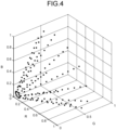
- FIG. 4 is a graph illustrating how distribution points of the complex amplitudes Z ij illustrated in FIG. 3 are transferred to a three-dimensional RGB color space by mapping.
- the horizontal axis represents a real number axis
- the vertical axis represents an imaginary number axis.
- the color space conversion unit 13 thus converts the value of each complex amplitude Z ij by continuous and smooth mapping.
- the color space conversion unit 13 outputs a value included in a standard color space domain.
- the color space domain is set to a range of 0 ⁇ r, g, b ⁇ 1.
- the color space conversion unit 13 outputs a value that can compatibly express a negative amplitude.
- the color space conversion unit 13 can accurately quantize the phase and the amplitude level.
- the window function is not limited to the Hann window function.
- the window function can be selected as appropriate depending on a required characteristic such as frequency resolution or dynamic range.
- the overlap ratio of the Fourier transform frame does not need to be 50%, or the Fourier transform frames need not overlap.
- the overlap ratio and whether or not the Fourier transform frames should overlap can be determined taking into consideration a processing load, signal detection characteristics, or signal identification characteristics of the signal processing device 1.
- the Fourier transform is not limited to FFT. A Fourier transform in which the frame length of the Fourier transform frame is not a value of a power of two may be applied.
- Reliability information may be added to the signal type information that is output.
- the signal types may be hierarchized, and the reliability information may be added for each hierarchy.
- the hierarchization of the signal types means that, for example, when binary phase shift keying (BPSK), quaternary phase shift keying (QPSK), and 8 phase shift keying (8PSK) are set as lower signal types, a signal type including all the lower signal types such as phase shift keying (PSK) is set as a higher signal type. While the higher signal type generally corresponds to broader classification of the signal types than the lower signal types, the higher signal type has an advantage that higher reliability can be obtained.
- BPSK binary phase shift keying
- QPSK quaternary phase shift keying
- 8PSK 8 phase shift keying
- the deep learning processing unit 14 further performs learning with the spectrogram data having been subjected to the color space conversion described above and a label representing the signal type or a position on the time-frequency plane.
- the spectrogram data is learning data.
- the label is added to the learning data.
- the deep learning processing unit 14 can efficiently improve the accuracy of detecting or identifying a signal by such learning.
- a machine learning model such as YOLOv3 or YOLOv4 used for object detection may be used as the learning model having been trained using the color image.
- Darknet-53 may be used as the convolutional layer 15.
- the learning data and the label may be obtained by adding a label to real data collected in the real world, or may be data and a label generated by simulation. Alternatively, the learning data and the label may be obtained by adding a label to data obtained by processing real data.
- the deep learning processing unit 14 may perform learning by variously changing a combination of a signal-noise (SN) ratio, signal power, a carrier frequency, a signal band, a carrier phase, a modulation system, a symbol rate, a symbol phase, a pulse period, a pulse duty, a pulse phase, a chirp rate, a fading effect, etc. of a signal.
- SN signal-noise
- the signal processing device 1 can improve the accuracy of detecting or identifying a signal.
- the signal processing device 1 performs mapping of the complex plane onto a conical surface of the RGB space.
- the signal processing device 1 can convert the value of the complex amplitude by continuous and smooth mapping without changing the brightness even when the phase of the complex number changes.
- the signal processing device 1 can keep each of the amount of information and the characteristics of the original spectrogram data by symmetric conversion between the complex number and the three-color value. As a result, the signal processing device 1 can obtain good detection accuracy and good identification accuracy when combined with deep learning based on human vision.
- the signal processing device 1 converts the phase angles of the complex amplitudes in the frequency domain into the hues and also performs conversion that associates the absolute values of the complex amplitudes with the brightness, thereby generating the spectrogram data defined so as to correspond to the time-frequency plane.
- the signal processing device 1 thus has the effect of accurately detecting or identifying a signal from the spectrogram data by deep learning.
- the first embodiment has illustrated the example of mapping that converts the phase angle of the complex amplitude "Z” into the hue and also performs conversion that associates the logarithm of the absolute value of the complex amplitude "Z” with the brightness in the RGB color space.
- the color space conversion unit 13 may apply a simple conversion calculation method such as keeping the absolute value of the complex amplitude "Z” linear or applying a function that gradually decreases a slope of the absolute value of the complex amplitude "Z”.
- the color space conversion unit 13 can use any method to perform the conversion that associates the absolute value of the complex amplitude with the brightness.
- the color space conversion unit 13 can improve the efficiency of the calculation by applying the simple conversion calculation method.
- the signal processing device 1 has an effect of being able to detect or identify a signal more efficiently than the case of the first embodiment.
- the first and second embodiments have illustrated the example of mapping that converts the phase angle of the complex amplitude "Z" into the hue in the RGB color space.
- the conversion expression expressed by expression (1) may be adjusted so as to increase the maximum value of the brightness while decreasing the saturation.
- the color space conversion unit 13 can quantize the absolute value of the complex amplitude "Z" with higher accuracy.
- the third embodiment performs color space conversion that enables quantization of the absolute value of the complex amplitude "Z" with higher accuracy.
- the signal processing device 1 has an effect of detecting or identifying a signal with higher accuracy than in the case of the first or second embodiment, depending on a condition of the signal to be detected or identified such as having a high dynamic range.
- the signal processing device 1 can be implemented by hardware having a configuration illustrated in FIG. 5 or 6 .
- FIG. 5 is a diagram illustrating a first configuration example of the hardware for implementing the signal processing device 1 according to the first to third embodiments.
- FIG. 5 illustrates a configuration in a case where the main part of the signal processing device 1, that is, each of the window function unit 11, the Fourier transform unit 12, the color space conversion unit 13, and the deep learning processing unit 14, is implemented by processing circuitry 22 that is dedicated hardware.
- the processing circuitry 22 is, for example, an application specific integrated circuit (ASIC), a field programmable gate array (FPGA), or a circuit obtained by a combination thereof. Note that, in the example illustrated in FIG.
- ASIC application specific integrated circuit
- FPGA field programmable gate array
- the window function unit 11, the Fourier transform unit 12, the color space conversion unit 13, and the deep learning processing unit 14 are implemented by the single processing circuitry 22, but the present disclosure is not limited thereto.
- the hardware may include a plurality of pieces of the processing circuitry 22 to implement the window function unit 11, the Fourier transform unit 12, the color space conversion unit 13, and the deep learning processing unit 14 by different pieces of the processing circuitry 22.
- An input unit 21 is a circuit that receives an input signal to the signal processing device 1, that is, time-series signal data thereto, from the outside.
- An output unit 23 is a circuit that outputs a signal generated by the signal processing device 1, that is, a result of signal detection or identification, to the outside.
- FIG. 6 is a diagram illustrating a second configuration example of the hardware for implementing the signal processing device 1 according to the first to third embodiments.
- FIG. 6 illustrates a configuration in a case where the function of the processing circuitry 22 illustrated in FIG. 5 is implemented by a control circuit including a processor 24 and a memory 25.
- the processor 24 is a central processing unit (CPU).
- the processor 24 may be an arithmetic unit, a microprocessor, a microcomputer, or a digital signal processor (DSP).
- DSP digital signal processor
- the memory 25 is, for example, a non-volatile or volatile memory such as a random access memory (RAM), a read only memory (ROM), a flash memory, an erasable programmable read only memory (EPROM), or an electrically erasable programmable read only memory (EEPROM (registered trademark)).
- RAM random access memory
- ROM read only memory
- EPROM erasable programmable read only memory
- EEPROM electrically erasable programmable read only memory
- the processor 24 executes a program describing processing that allows the processor 24 to operate as the window function unit 11, the Fourier transform unit 12, the color space conversion unit 13, and the deep learning processing unit 14.
- a program is stored in advance in the memory 25.
- the processor 24 reads and executes the program stored in the memory 25 to operate as the window function unit 11, the Fourier transform unit 12, the color space conversion unit 13, and the deep learning processing unit 14.
- window function unit 11 the Fourier transform unit 12, the color space conversion unit 13, and the deep learning processing unit 14 may be implemented by the processor 24 and the memory 25, and the rest may be implemented by dedicated hardware similar to the processing circuitry 22 illustrated in FIG. 5 .
- the program to be executed by the processor 24 is not limited to the program stored in advance in the memory 25.
- the program to be executed by the processor 24 may be a program stored in a storage medium that can be read by a computer system.
- the program stored in the storage medium may be stored in the memory 25.
- the storage medium may be a portable storage medium being a flexible disk, or may be a flash memory being a semiconductor memory.
- the program may be installed on the signal processing device 1 from another computer or a server device via a communication network.
- the configurations illustrated in the above embodiments illustrate an example of the content of the present disclosure.
- the configurations of the embodiments can be combined with another known technique.
- the configurations of the embodiments may be combined together as appropriate.
- a part of the configurations of the embodiments can be omitted or modified without departing from the scope of the present disclosure.
- 1 signal processing device 1 signal processing device; 2 ADC; 3 system; 11 window function unit; 12 Fourier transform unit; 13 color space conversion unit; 14 deep learning processing unit; 15 convolutional layer; 16 fully connected layer; 21 input unit; 22 processing circuitry; 23 output unit; 24 processor; 25 memory.
Landscapes
- Engineering & Computer Science (AREA)
- Physics & Mathematics (AREA)
- Theoretical Computer Science (AREA)
- General Physics & Mathematics (AREA)
- Mathematical Physics (AREA)
- Data Mining & Analysis (AREA)
- Software Systems (AREA)
- Health & Medical Sciences (AREA)
- Evolutionary Computation (AREA)
- General Health & Medical Sciences (AREA)
- General Engineering & Computer Science (AREA)
- Life Sciences & Earth Sciences (AREA)
- Artificial Intelligence (AREA)
- Computing Systems (AREA)
- Spectroscopy & Molecular Physics (AREA)
- Biomedical Technology (AREA)
- Computational Linguistics (AREA)
- Biophysics (AREA)
- Databases & Information Systems (AREA)
- Molecular Biology (AREA)
- Multimedia (AREA)
- Computational Mathematics (AREA)
- Mathematical Analysis (AREA)
- Mathematical Optimization (AREA)
- Pure & Applied Mathematics (AREA)
- Computer Vision & Pattern Recognition (AREA)
- Algebra (AREA)
- Medical Informatics (AREA)
- Chemical & Material Sciences (AREA)
- Analytical Chemistry (AREA)
- Biochemistry (AREA)
- Immunology (AREA)
- Pathology (AREA)
- Image Analysis (AREA)
- Complex Calculations (AREA)
- Spectrometry And Color Measurement (AREA)
- Investigating Or Analysing Materials By Optical Means (AREA)
Abstract
Description
- The present disclosure relates to a signal processing device that detects or identifies a signal, a control circuit, a storage medium, and a signal processing method.
- Known systems of detecting and identifying objects by deep learning from image information based on a Red-Green-Blue (RGB) color space including three components of R, G, and
B. Patent Literature 1 discloses a method of detecting and identifying an object using deep learning by converting an image signal based on an RGB color space into image information based on a Hue-Saturation-Value (HSV) color space. The image information based on the HSV color space and the image information based on the RGB color space both have three degrees of freedom per pixel. - Patent Literature 1:
U.S. Patent No. 10185881 - For a system that converts a time-series signal into a spectrogram and uses deep learning to detect or identify a signal on a time-frequency plane, information corresponding to one pixel is a complex number value with two degrees of freedom. In this case, the number of degrees of freedom of the information per pixel is different from that in the case of
Patent Literature 1 above. As a result, the color space conversion by the conventional method disclosed inPatent Literature 1 above fails to execute appropriate processing for accurately detecting or identifying a signal. The conventional technique thus suffers from a problem of difficulty in accurately detecting or identifying a signal from spectrogram data by deep learning. - The present disclosure has been made in view of the above, and an object thereof is to provide a signal processing device capable of accurately detecting or identifying a signal from spectrogram data by deep learning.
- To solve the above problem and achieve the object, a signal processing device according to the present disclosure comprises: a window function unit to perform window function processing on a Fourier transform frame cut from time-series signal data; a Fourier transform unit to transform, into information in a frequency domain, the Fourier transform frame subjected to the window function processing; a color space conversion unit to generate spectrogram data by converting a phase angle of a complex amplitude in the frequency domain into a hue and performing conversion that associates an absolute value of the complex amplitude with brightness by mapping, the spectrogram data being defined so as to correspond to a two-dimensional plane of time and frequency; and a deep learning processing unit to detect or identify a signal by convolutional processing and fully connected processing on the spectrogram data.
- The signal processing device according to the present disclosure has an effect of accurately detecting or identifying a signal from the spectrogram data by deep learning.
-
-
FIG. 1 is a diagram illustrating a configuration of a system including a signal processing device according to a first embodiment. -
FIG. 2 is a block diagram illustrating a functional configuration of the signal processing device according to the first embodiment. -
FIG. 3 is a graph illustrating how complex amplitudes are distributed on a two-dimensional complex plane in the first embodiment. -
FIG. 4 is a graph illustrating how distribution points of the complex amplitudes illustrated inFIG. 3 are transferred to a three-dimensional RGB color space by mapping. -
FIG. 5 is a diagram illustrating a first configuration example of hardware for implementing the signal processing device according to the first to third embodiments. -
FIG. 6 is a diagram illustrating a second configuration example of the hardware for implementing the signal processing device according to the first to third embodiments. - A signal processing device, a control circuit, a storage medium, and a signal processing method according to embodiments will be hereinafter described in detail with reference to the drawings.
-
FIG. 1 is a diagram illustrating a configuration of asystem 3 including asignal processing device 1 according to a first embodiment. Thesystem 3 detects or identifies a signal from waveform data on a received signal. Thesystem 3 includes thesignal processing device 1 and an analog to digital converter (ADC) 2. The ADC 2 converts the received signal into time-series signal data by sampling the signal received by thesystem 3 at equal time intervals. The ADC 2 outputs the time-series signal data to thesignal processing device 1. Upon receiving the time-series signal data, thesignal processing device 1 performs processing for detecting or identifying a signal. The received signal is a signal representing image information. Thesignal processing device 1 performs detection or identification of a signal indicating an image of an object. The detection or identification of a signal refers to detecting signal-related information such as a signal type or a carrier frequency. The signal type is a type of a modulation system or a type based on a code sequence of a modulated signal. - Next, a functional configuration of the
signal processing device 1 will be described.FIG. 2 is a block diagram illustrating the functional configuration of thesignal processing device 1 according to the first embodiment. Thesignal processing device 1 includes awindow function unit 11, a Fouriertransform unit 12, a colorspace conversion unit 13, and a deep learning processing unit 14. - The
window function unit 11 performs processing of cutting out, from the time-series signal data, continuous time-series signals having a certain time length. This continuous time-series signals are defined as a Fourier transform frame. In cutting out the Fourier transform frame, thewindow function unit 11 allows the Fourier transform frame and the preceding Fourier transform frame to overlap on a time axis by 50% of each frame length and allows the Fourier transform frame and the following Fourier transform frame to overlap on a time axis by 50% of each frame length. Thewindow function unit 11 performs window function processing on the Fourier transform frame by multiplying the Fourier transform frame by a Hann window coefficient sequence. - The Fourier
transform unit 12 applies fast Fourier transform (FFT) to the Fourier transform frame having been subjected to the window function processing, such that the Fouriertransform unit 12 transforms the Fourier transform frame into information in a frequency domain. - The color
space conversion unit 13 performs mapping to convert phase angles of complex amplitudes in the frequency domain into hues and also perform conversion to associates logarithms of absolute values of the complex amplitudes with brightness, thereby generating spectrogram data defined so as to correspond to a two-dimensional plane of time and frequency. The colorspace conversion unit 13 outputs the generated spectrogram data to the deep learning processing unit 14. Note that the two-dimensional plane of time and frequency is referred to as a time-frequency plane. - Using a weight parameter obtained by deep learning processing, the deep learning processing unit 14 to perform, on the spectrogram data, inference processing for detecting or identifying a signal. That is, the deep learning processing unit 14 executes a learning phase for detecting or identifying a signal and an inference phase for detecting or identifying a signal. Specifically, the deep learning processing unit 14 detects signal-related information, using a learning model having the weight parameter adjusted by deep learning. Such a model includes a convolutional neural network with the spectrogram data as an input and the signal-related information as an output. The convolutional neural network is a multilayer neural network, and includes a plurality of
convolutional layers 15 and a fully connectedlayer 16. The deep learning processing unit 14 detects or identifies a signal by performing convolutional processing and fully connected processing on the spectrogram data. - The
convolutional layer 15 is a layer that performs processing such as extracting information in a specific region from an image indicated by the spectrogram data. The fully connectedlayer 16 is a layer in which all neurons of a preceding layer and a succeeding layer are connected together. In the inference phase, the deep learning processing unit 14 performs the convolutional processing in the plurality of theconvolutional layers 15 and the fully connected processing in the fully connectedlayer 16, and outputs information on the signal type, a value of the carrier frequency, or the like. - A conversion expression representing the color space conversion in the color
space conversion unit 13 is expressed by the following expression (1).
Formula 1:
- As expressed above, the color
space conversion unit 13 converts a phase angle of a complex amplitude "Z" into a hue and also performs conversion that associates a logarithm of an absolute value of the complex amplitude "Z" with brightness in the RGB color space. In the expression, "C (r, g, b)" represents values of the components in the RGB color space. Moreover, "abs (Z)" represents the absolute value of the complex amplitude "Z". Moreover, "arg (Z)" represents an argument of the complex amplitude "Z". That is, the "arg (Z)" represents the phase angle of the complex amplitude "Z". Moreover, "Minlog abs (Z)" represents the minimum value that "log abs (Z)" takes. Moreover, "Rangelog abs (Z)" represents a range of the value that "log abs (Z)" takes. The spectrogram data is two-dimensional array data arranged along each of a time axis and a frequency axis. The colorspace conversion unit 13 performs conversion according to expression (1) on each of a plurality of complex amplitudes Zij included in the spectrogram data. The subscript "i" indicates an array on the time axis. The subscript "j" indicates an array on the frequency axis. -
FIG. 3 is a graph illustrating how the complex amplitudes Zij are distributed on a two-dimensional complex plane in the first embodiment.FIG. 4 is a graph illustrating how distribution points of the complex amplitudes Zij illustrated inFIG. 3 are transferred to a three-dimensional RGB color space by mapping. In the graph illustrated inFIG. 3 , the horizontal axis represents a real number axis, and the vertical axis represents an imaginary number axis. By the color space conversion expressed by expression (1), the colorspace conversion unit 13 converts the phase angle of each complex amplitude Zij into a hue, and also performs conversion that associates the logarithm of the absolute value of each complex amplitude Zij with brightness. The colorspace conversion unit 13 thus converts the value of each complex amplitude Zij by continuous and smooth mapping. The colorspace conversion unit 13 outputs a value included in a standard color space domain. The color space domain is set to a range of 0 ≤ r, g, b ≤ 1. The colorspace conversion unit 13 outputs a value that can compatibly express a negative amplitude. The colorspace conversion unit 13 can accurately quantize the phase and the amplitude level. - Note that the window function is not limited to the Hann window function. The window function can be selected as appropriate depending on a required characteristic such as frequency resolution or dynamic range. Moreover, the overlap ratio of the Fourier transform frame does not need to be 50%, or the Fourier transform frames need not overlap. The overlap ratio and whether or not the Fourier transform frames should overlap can be determined taking into consideration a processing load, signal detection characteristics, or signal identification characteristics of the
signal processing device 1. The Fourier transform is not limited to FFT. A Fourier transform in which the frame length of the Fourier transform frame is not a value of a power of two may be applied. - Reliability information may be added to the signal type information that is output. The signal types may be hierarchized, and the reliability information may be added for each hierarchy. The hierarchization of the signal types means that, for example, when binary phase shift keying (BPSK), quaternary phase shift keying (QPSK), and 8 phase shift keying (8PSK) are set as lower signal types, a signal type including all the lower signal types such as phase shift keying (PSK) is set as a higher signal type. While the higher signal type generally corresponds to broader classification of the signal types than the lower signal types, the higher signal type has an advantage that higher reliability can be obtained.
- Next, the learning phase will be described. With the learning model having the weight parameter adjusted by the deep learning processing using a color image corresponding to general human vision, the deep learning processing unit 14 further performs learning with the spectrogram data having been subjected to the color space conversion described above and a label representing the signal type or a position on the time-frequency plane. The spectrogram data is learning data. The label is added to the learning data. The deep learning processing unit 14 can efficiently improve the accuracy of detecting or identifying a signal by such learning.
- A machine learning model such as YOLOv3 or YOLOv4 used for object detection may be used as the learning model having been trained using the color image. Darknet-53 may be used as the
convolutional layer 15. - The learning data and the label may be obtained by adding a label to real data collected in the real world, or may be data and a label generated by simulation. Alternatively, the learning data and the label may be obtained by adding a label to data obtained by processing real data.
- In the case where the learning data and the label are generated by simulation, or where the label is added to the learning data obtained by processing the real data, the deep learning processing unit 14 may perform learning by variously changing a combination of a signal-noise (SN) ratio, signal power, a carrier frequency, a signal band, a carrier phase, a modulation system, a symbol rate, a symbol phase, a pulse period, a pulse duty, a pulse phase, a chirp rate, a fading effect, etc. of a signal. As a result, the
signal processing device 1 can improve the accuracy of detecting or identifying a signal. - In a conventional library or package used in deep learning for object detection or identification, learning and inference have been performed using three-color values such as RGB values based on human vision or monochrome values. The three-color values have three degrees of freedom. The monochrome values have one degree of freedom. In a case where a value of a complex number having two degrees of freedom is converted into a three-color value, a processing method combinable with a conventional deep learning library or the like for accurately detecting or identifying a signal has been uncertain. For example, when an in-phase (I) value that is a value on a real number axis and a quadrature-phase (Q) value that is a value on an imaginary number axis in a complex plane are simply substituted into corresponding R and G values, the values take negative values, so that appropriate processing cannot be performed. Alternatively, in a case of application of an offset or processing such as taking a logarithm to make the values of "I" and "Q" fall within a range of 0 ≤ r, g ≤ 1, which is a domain of a first quadrant in a two-dimensional plane of R and G, the hue and brightness change simultaneously every time the phase of the complex number changes. Since humans use vision to perform recognition based on brightness, it is not appropriate that the brightness changes every time the phase of a signal received asynchronously changes.
- On the other hand, the
signal processing device 1 according to the first embodiment performs mapping of the complex plane onto a conical surface of the RGB space. Thesignal processing device 1 can convert the value of the complex amplitude by continuous and smooth mapping without changing the brightness even when the phase of the complex number changes. Thesignal processing device 1 can keep each of the amount of information and the characteristics of the original spectrogram data by symmetric conversion between the complex number and the three-color value. As a result, thesignal processing device 1 can obtain good detection accuracy and good identification accuracy when combined with deep learning based on human vision. - According to the first embodiment, the
signal processing device 1 converts the phase angles of the complex amplitudes in the frequency domain into the hues and also performs conversion that associates the absolute values of the complex amplitudes with the brightness, thereby generating the spectrogram data defined so as to correspond to the time-frequency plane. Thesignal processing device 1 thus has the effect of accurately detecting or identifying a signal from the spectrogram data by deep learning. - As expressed by expression (1), the first embodiment has illustrated the example of mapping that converts the phase angle of the complex amplitude "Z" into the hue and also performs conversion that associates the logarithm of the absolute value of the complex amplitude "Z" with the brightness in the RGB color space. In a second embodiment, instead of converting the absolute value of the complex amplitude "Z" into the logarithm, the color
space conversion unit 13 may apply a simple conversion calculation method such as keeping the absolute value of the complex amplitude "Z" linear or applying a function that gradually decreases a slope of the absolute value of the complex amplitude "Z". The colorspace conversion unit 13 can use any method to perform the conversion that associates the absolute value of the complex amplitude with the brightness. The colorspace conversion unit 13 can improve the efficiency of the calculation by applying the simple conversion calculation method. According to the second embodiment, thesignal processing device 1 has an effect of being able to detect or identify a signal more efficiently than the case of the first embodiment. - As expressed by expression (1), the first and second embodiments have illustrated the example of mapping that converts the phase angle of the complex amplitude "Z" into the hue in the RGB color space. In a third embodiment, the conversion expression expressed by expression (1) may be adjusted so as to increase the maximum value of the brightness while decreasing the saturation. As a result, the color
space conversion unit 13 can quantize the absolute value of the complex amplitude "Z" with higher accuracy. - The third embodiment performs color space conversion that enables quantization of the absolute value of the complex amplitude "Z" with higher accuracy. The
signal processing device 1 has an effect of detecting or identifying a signal with higher accuracy than in the case of the first or second embodiment, depending on a condition of the signal to be detected or identified such as having a high dynamic range. - Next, hardware for implementing the
signal processing device 1 according to the first to third embodiments will be described. Thesignal processing device 1 can be implemented by hardware having a configuration illustrated inFIG. 5 or 6 . -
FIG. 5 is a diagram illustrating a first configuration example of the hardware for implementing thesignal processing device 1 according to the first to third embodiments.FIG. 5 illustrates a configuration in a case where the main part of thesignal processing device 1, that is, each of thewindow function unit 11, theFourier transform unit 12, the colorspace conversion unit 13, and the deep learning processing unit 14, is implemented by processingcircuitry 22 that is dedicated hardware. Theprocessing circuitry 22 is, for example, an application specific integrated circuit (ASIC), a field programmable gate array (FPGA), or a circuit obtained by a combination thereof. Note that, in the example illustrated inFIG. 5 , thewindow function unit 11, theFourier transform unit 12, the colorspace conversion unit 13, and the deep learning processing unit 14 are implemented by thesingle processing circuitry 22, but the present disclosure is not limited thereto. The hardware may include a plurality of pieces of theprocessing circuitry 22 to implement thewindow function unit 11, theFourier transform unit 12, the colorspace conversion unit 13, and the deep learning processing unit 14 by different pieces of theprocessing circuitry 22. - An input unit 21 is a circuit that receives an input signal to the
signal processing device 1, that is, time-series signal data thereto, from the outside. Anoutput unit 23 is a circuit that outputs a signal generated by thesignal processing device 1, that is, a result of signal detection or identification, to the outside. -
FIG. 6 is a diagram illustrating a second configuration example of the hardware for implementing thesignal processing device 1 according to the first to third embodiments.FIG. 6 illustrates a configuration in a case where the function of theprocessing circuitry 22 illustrated inFIG. 5 is implemented by a control circuit including a processor 24 and a memory 25. The processor 24 is a central processing unit (CPU). The processor 24 may be an arithmetic unit, a microprocessor, a microcomputer, or a digital signal processor (DSP). The memory 25 is, for example, a non-volatile or volatile memory such as a random access memory (RAM), a read only memory (ROM), a flash memory, an erasable programmable read only memory (EPROM), or an electrically erasable programmable read only memory (EEPROM (registered trademark)). - In a case where the main part of the
signal processing device 1 is implemented by the processor 24 and the memory 25, the processor 24 executes a program describing processing that allows the processor 24 to operate as thewindow function unit 11, theFourier transform unit 12, the colorspace conversion unit 13, and the deep learning processing unit 14. Such a program is stored in advance in the memory 25. The processor 24 reads and executes the program stored in the memory 25 to operate as thewindow function unit 11, theFourier transform unit 12, the colorspace conversion unit 13, and the deep learning processing unit 14. - Note that some of the
window function unit 11, theFourier transform unit 12, the colorspace conversion unit 13, and the deep learning processing unit 14 may be implemented by the processor 24 and the memory 25, and the rest may be implemented by dedicated hardware similar to theprocessing circuitry 22 illustrated inFIG. 5 . - Note that the program to be executed by the processor 24 is not limited to the program stored in advance in the memory 25. The program to be executed by the processor 24 may be a program stored in a storage medium that can be read by a computer system. The program stored in the storage medium may be stored in the memory 25. The storage medium may be a portable storage medium being a flexible disk, or may be a flash memory being a semiconductor memory. The program may be installed on the
signal processing device 1 from another computer or a server device via a communication network. - The configurations illustrated in the above embodiments illustrate an example of the content of the present disclosure. The configurations of the embodiments can be combined with another known technique. The configurations of the embodiments may be combined together as appropriate. A part of the configurations of the embodiments can be omitted or modified without departing from the scope of the present disclosure.
- 1 signal processing device; 2 ADC; 3 system; 11 window function unit; 12 Fourier transform unit; 13 color space conversion unit; 14 deep learning processing unit; 15 convolutional layer; 16 fully connected layer; 21 input unit; 22 processing circuitry; 23 output unit; 24 processor; 25 memory.
Claims (6)
- A signal processing device comprising:a window function unit to perform window function processing on a Fourier transform frame cut from time-series signal data;a Fourier transform unit to transform, into information in a frequency domain, the Fourier transform frame subjected to the window function processing;a color space conversion unit to generate spectrogram data by converting a phase angle of a complex amplitude in the frequency domain into a hue and performing conversion that associates an absolute value of the complex amplitude with brightness by mapping, the spectrogram data being defined so as to correspond to a two-dimensional plane of time and frequency; anda deep learning processing unit to detect or identify a signal by convolutional processing and fully connected processing on the spectrogram data.
- The signal processing device according to claim 1, wherein the color space conversion unit performs conversion that associates a logarithm of the absolute value of the complex amplitude with the brightness.
- The signal processing device according to claim 1, wherein, in the conversion that associates the absolute value of the complex amplitude with the brightness, the color space conversion unit applies a function that gradually decreases a slope of the absolute value of the complex amplitude.
- A control circuit to control a signal processing device, the control circuit causing the signal processing device to execute:a step of performing window function processing on a Fourier transform frame cut from time-series signal data;a step of transforming, into information in a frequency domain, the Fourier transform frame subjected to the window function processing;a step of generating spectrogram data by converting a phase angle of a complex amplitude in the frequency domain into a hue and performing conversion that associates an absolute value of the complex amplitude with brightness by mapping, the spectrogram data being defined so as to correspond to a two-dimensional plane of time and frequency; anda step of performing processing to detect or identify a signal by convolutional processing and fully connected processing on the spectrogram data.
- A storage medium to store a program for controlling a signal processing device, wherein
the program causes the signal processing device to execute:a step of performing window function processing on a Fourier transform frame cut from time-series signal data;a step of transforming, into information in a frequency domain, the Fourier transform frame subjected to the window function processing;a step of generating spectrogram data by converting a phase angle of a complex amplitude in the frequency domain into a hue and performing conversion that associates an absolute value of the complex amplitude with brightness by mapping, the spectrogram data being defined so as to correspond to a two-dimensional plane of time and frequency; anda step of performing processing to detect or identify a signal by convolutional processing and fully connected processing on the spectrogram data. - A signal processing method to be executed by a signal processing device, the signal processing method comprising:a step of performing window function processing on a Fourier transform frame cut from time-series signal data;a step of transforming, into information in a frequency domain, the Fourier transform frame subjected to the window function processing;a step of generating spectrogram data by converting a phase angle of a complex amplitude in the frequency domain into a hue and performing conversion that associates an absolute value of the complex amplitude with brightness by mapping, the spectrogram data being defined so as to correspond to a two-dimensional plane of time and frequency; anda step of performing processing to detect or identify a signal by convolutional processing and fully connected processing on the spectrogram data.
Applications Claiming Priority (1)
| Application Number | Priority Date | Filing Date | Title |
|---|---|---|---|
| PCT/JP2021/008198 WO2022185452A1 (en) | 2021-03-03 | 2021-03-03 | Signal processing apparatus, control circuit, storage medium, and signal processing method |
Publications (3)
| Publication Number | Publication Date |
|---|---|
| EP4286809A1 true EP4286809A1 (en) | 2023-12-06 |
| EP4286809A4 EP4286809A4 (en) | 2024-01-10 |
| EP4286809B1 EP4286809B1 (en) | 2025-12-03 |
Family
ID=81213694
Family Applications (1)
| Application Number | Title | Priority Date | Filing Date |
|---|---|---|---|
| EP21929028.5A Active EP4286809B1 (en) | 2021-03-03 | 2021-03-03 | Signal processing device, control circuit, storage medium, and signal processing method |
Country Status (4)
| Country | Link |
|---|---|
| US (1) | US12602832B2 (en) |
| EP (1) | EP4286809B1 (en) |
| JP (1) | JP7038922B1 (en) |
| WO (1) | WO2022185452A1 (en) |
Families Citing this family (2)
| Publication number | Priority date | Publication date | Assignee | Title |
|---|---|---|---|---|
| JP7672104B2 (en) * | 2021-07-21 | 2025-05-07 | パナソニックIpマネジメント株式会社 | LEARNING APPARATUS, LEARNING METHOD, AND NON-DESTRUCTIVE INSPECTION SYSTEM |
| CN119693765B (en) * | 2024-12-02 | 2026-02-13 | 成都玖锦科技有限公司 | Model training and signal detection method and device, medium and electronic equipment |
Family Cites Families (7)
| Publication number | Priority date | Publication date | Assignee | Title |
|---|---|---|---|---|
| CN101401101B (en) * | 2006-03-10 | 2014-06-04 | 皇家飞利浦电子股份有限公司 | Methods and systems for identification of DNA patterns through spectral analysis |
| JP6281973B2 (en) * | 2013-12-10 | 2018-02-21 | 国立大学法人京都大学 | Method for expressing properties of a mixture sample, method for evaluating properties of a mixture sample, method for identifying attributes of a mixture sample, and method for processing an electromagnetic wave signal derived from a mixture sample |
| WO2017181291A1 (en) * | 2016-04-22 | 2017-10-26 | Nanoleaf (Hk) Limited | Systems and methods for connecting and controlling configurable lighting units |
| US10185881B2 (en) | 2016-11-23 | 2019-01-22 | Ford Global Technologies, Llc | Traffic-light detection and classification using computer vision and deep learning |
| US10341795B2 (en) * | 2016-11-29 | 2019-07-02 | The Curators Of The University Of Missouri | Log complex color for visual pattern recognition of total sound |
| JP7271244B2 (en) * | 2019-03-15 | 2023-05-11 | 本田技研工業株式会社 | CNN processing device, CNN processing method, and program |
| KR102191007B1 (en) * | 2019-04-19 | 2020-12-14 | 한국과학기술원 | Three dimensional image generating method and apparatus |
-
2021
- 2021-03-03 WO PCT/JP2021/008198 patent/WO2022185452A1/en not_active Ceased
- 2021-03-03 EP EP21929028.5A patent/EP4286809B1/en active Active
- 2021-03-03 JP JP2021544249A patent/JP7038922B1/en active Active
-
2023
- 2023-08-23 US US18/237,127 patent/US12602832B2/en active Active
Also Published As
| Publication number | Publication date |
|---|---|
| WO2022185452A1 (en) | 2022-09-09 |
| EP4286809A4 (en) | 2024-01-10 |
| JP7038922B1 (en) | 2022-03-18 |
| US12602832B2 (en) | 2026-04-14 |
| JPWO2022185452A1 (en) | 2022-09-09 |
| US20230394709A1 (en) | 2023-12-07 |
| CA3212158A1 (en) | 2022-09-09 |
| EP4286809B1 (en) | 2025-12-03 |
Similar Documents
| Publication | Publication Date | Title |
|---|---|---|
| US12602832B2 (en) | Signal processing device, control circuit, storage medium, and signal processing method | |
| Ahrabian et al. | Synchrosqueezing-based time-frequency analysis of multivariate data | |
| US20200097775A1 (en) | Systems and methods for detecting and classifying anomalous features in one-dimensional data | |
| US20120257829A1 (en) | Representing Signals for Classification | |
| EP4030381A1 (en) | Artificial-intelligence-based image processing method and apparatus, and device and storage medium | |
| CN113052317A (en) | Method and device for acquiring quantum state information, quantum measurement and control system and computer | |
| EP3631512A1 (en) | Multipath mitigation for time of flight system | |
| EP3891526B1 (en) | Multipath mitigation for time of flight system | |
| CN106330805B (en) | A kind of signal modulation mode automatic identifying method and system | |
| US10060961B1 (en) | Spectrogram compression for data transmission | |
| US11316542B2 (en) | Signal analysis method and signal analysis module | |
| US20210006390A1 (en) | Method for Generating Digital Quantum Chaotic Wavepacket Signals | |
| CN113780106A (en) | Deep learning signal detection method based on radio waveform data input | |
| CN115617010A (en) | Gas turbine sensor fault diagnosis method and system based on visual enhancement | |
| JPS61273688A (en) | Feature variation detector for detecting abrupt change in feature of image area divided into discrete pixel | |
| WO2007027839A2 (en) | Device and methods for enhanced matched filtering based on correntropy | |
| CA3212158C (en) | Signal processing device, control circuit, storage medium, and signal processing method | |
| JP4030667B2 (en) | Modulation identification apparatus, modulation identification method, and recording medium | |
| Tavakoli et al. | Radar signal recognition by CWD picture features | |
| JP4871191B2 (en) | Target signal section estimation device, target signal section estimation method, target signal section estimation program, and recording medium | |
| US11936405B2 (en) | Method for compressing digital signal data and signal compressor module | |
| KR20210073262A (en) | Device and method for Signal Analysis of Lidar System | |
| CN113536897B (en) | A method for identifying modulation types of aliased signals based on time-frequency analysis and constellation diagram analysis | |
| Subbarao et al. | A novel technique for automatic modulation classification and time-frequency analysis of digitally modulated signals | |
| CHACHOUA et al. | Radio signal classification using deep learning |
Legal Events
| Date | Code | Title | Description |
|---|---|---|---|
| STAA | Information on the status of an ep patent application or granted ep patent |
Free format text: STATUS: THE INTERNATIONAL PUBLICATION HAS BEEN MADE |
|
| PUAI | Public reference made under article 153(3) epc to a published international application that has entered the european phase |
Free format text: ORIGINAL CODE: 0009012 |
|
| STAA | Information on the status of an ep patent application or granted ep patent |
Free format text: STATUS: REQUEST FOR EXAMINATION WAS MADE |
|
| 17P | Request for examination filed |
Effective date: 20230828 |
|
| AK | Designated contracting states |
Kind code of ref document: A1 Designated state(s): AL AT BE BG CH CY CZ DE DK EE ES FI FR GB GR HR HU IE IS IT LI LT LU LV MC MK MT NL NO PL PT RO RS SE SI SK SM TR |
|
| A4 | Supplementary search report drawn up and despatched |
Effective date: 20231208 |
|
| RIC1 | Information provided on ipc code assigned before grant |
Ipc: G06F 17/14 20060101ALI20231204BHEP Ipc: G06V 10/88 20220101ALI20231204BHEP Ipc: G06V 10/82 20220101ALI20231204BHEP Ipc: G06V 10/56 20220101ALI20231204BHEP Ipc: G06F 17/10 20060101ALI20231204BHEP Ipc: G01N 21/27 20060101ALI20231204BHEP Ipc: G06N 3/04 20230101ALI20231204BHEP Ipc: G01J 3/46 20060101AFI20231204BHEP |
|
| DAV | Request for validation of the european patent (deleted) | ||
| DAX | Request for extension of the european patent (deleted) | ||
| STAA | Information on the status of an ep patent application or granted ep patent |
Free format text: STATUS: EXAMINATION IS IN PROGRESS |
|
| 17Q | First examination report despatched |
Effective date: 20240913 |
|
| GRAP | Despatch of communication of intention to grant a patent |
Free format text: ORIGINAL CODE: EPIDOSNIGR1 |
|
| STAA | Information on the status of an ep patent application or granted ep patent |
Free format text: STATUS: GRANT OF PATENT IS INTENDED |
|
| INTG | Intention to grant announced |
Effective date: 20250701 |
|
| GRAS | Grant fee paid |
Free format text: ORIGINAL CODE: EPIDOSNIGR3 |
|
| GRAA | (expected) grant |
Free format text: ORIGINAL CODE: 0009210 |
|
| STAA | Information on the status of an ep patent application or granted ep patent |
Free format text: STATUS: THE PATENT HAS BEEN GRANTED |
|
| AK | Designated contracting states |
Kind code of ref document: B1 Designated state(s): AL AT BE BG CH CY CZ DE DK EE ES FI FR GB GR HR HU IE IS IT LI LT LU LV MC MK MT NL NO PL PT RO RS SE SI SK SM TR |
|
| REG | Reference to a national code |
Ref country code: CH Ref legal event code: F10 Free format text: ST27 STATUS EVENT CODE: U-0-0-F10-F00 (AS PROVIDED BY THE NATIONAL OFFICE) Effective date: 20251203 Ref country code: GB Ref legal event code: FG4D |
|
| REG | Reference to a national code |
Ref country code: DE Ref legal event code: R096 Ref document number: 602021043915 Country of ref document: DE |
|
| REG | Reference to a national code |
Ref country code: IE Ref legal event code: FG4D |
|
| REG | Reference to a national code |
Ref country code: NL Ref legal event code: MP Effective date: 20251203 |
|
| PGFP | Annual fee paid to national office [announced via postgrant information from national office to epo] |
Ref country code: GB Payment date: 20260216 Year of fee payment: 6 |
|
| PG25 | Lapsed in a contracting state [announced via postgrant information from national office to epo] |
Ref country code: ES Free format text: LAPSE BECAUSE OF FAILURE TO SUBMIT A TRANSLATION OF THE DESCRIPTION OR TO PAY THE FEE WITHIN THE PRESCRIBED TIME-LIMIT Effective date: 20251203 |
|
| REG | Reference to a national code |
Ref country code: LT Ref legal event code: MG9D |
|
| PG25 | Lapsed in a contracting state [announced via postgrant information from national office to epo] |
Ref country code: NO Free format text: LAPSE BECAUSE OF FAILURE TO SUBMIT A TRANSLATION OF THE DESCRIPTION OR TO PAY THE FEE WITHIN THE PRESCRIBED TIME-LIMIT Effective date: 20260303 |
|
| PGFP | Annual fee paid to national office [announced via postgrant information from national office to epo] |
Ref country code: DE Payment date: 20260211 Year of fee payment: 6 |
|
| PG25 | Lapsed in a contracting state [announced via postgrant information from national office to epo] |
Ref country code: FI Free format text: LAPSE BECAUSE OF FAILURE TO SUBMIT A TRANSLATION OF THE DESCRIPTION OR TO PAY THE FEE WITHIN THE PRESCRIBED TIME-LIMIT Effective date: 20251203 Ref country code: HR Free format text: LAPSE BECAUSE OF FAILURE TO SUBMIT A TRANSLATION OF THE DESCRIPTION OR TO PAY THE FEE WITHIN THE PRESCRIBED TIME-LIMIT Effective date: 20251203 |
|
| PG25 | Lapsed in a contracting state [announced via postgrant information from national office to epo] |
Ref country code: RS Free format text: LAPSE BECAUSE OF FAILURE TO SUBMIT A TRANSLATION OF THE DESCRIPTION OR TO PAY THE FEE WITHIN THE PRESCRIBED TIME-LIMIT Effective date: 20260303 |
|
| PGFP | Annual fee paid to national office [announced via postgrant information from national office to epo] |
Ref country code: FR Payment date: 20260223 Year of fee payment: 6 |
|
| PG25 | Lapsed in a contracting state [announced via postgrant information from national office to epo] |
Ref country code: PL Free format text: LAPSE BECAUSE OF FAILURE TO SUBMIT A TRANSLATION OF THE DESCRIPTION OR TO PAY THE FEE WITHIN THE PRESCRIBED TIME-LIMIT Effective date: 20251203 |
|
| PG25 | Lapsed in a contracting state [announced via postgrant information from national office to epo] |
Ref country code: LV Free format text: LAPSE BECAUSE OF FAILURE TO SUBMIT A TRANSLATION OF THE DESCRIPTION OR TO PAY THE FEE WITHIN THE PRESCRIBED TIME-LIMIT Effective date: 20251203 |