EP4286775A1 - Control method for compressor, apparatus, device, storage medium, and cooling system - Google Patents
Control method for compressor, apparatus, device, storage medium, and cooling system Download PDFInfo
- Publication number
- EP4286775A1 EP4286775A1 EP21928799.2A EP21928799A EP4286775A1 EP 4286775 A1 EP4286775 A1 EP 4286775A1 EP 21928799 A EP21928799 A EP 21928799A EP 4286775 A1 EP4286775 A1 EP 4286775A1
- Authority
- EP
- European Patent Office
- Prior art keywords
- pressure
- compressor
- return air
- frequency
- exhaust
- Prior art date
- Legal status (The legal status is an assumption and is not a legal conclusion. Google has not performed a legal analysis and makes no representation as to the accuracy of the status listed.)
- Pending
Links
Images


Classifications
-
- F—MECHANICAL ENGINEERING; LIGHTING; HEATING; WEAPONS; BLASTING
- F25—REFRIGERATION OR COOLING; COMBINED HEATING AND REFRIGERATION SYSTEMS; HEAT PUMP SYSTEMS; MANUFACTURE OR STORAGE OF ICE; LIQUEFACTION SOLIDIFICATION OF GASES
- F25B—REFRIGERATION MACHINES, PLANTS OR SYSTEMS; COMBINED HEATING AND REFRIGERATION SYSTEMS; HEAT PUMP SYSTEMS
- F25B49/00—Arrangement or mounting of control or safety devices
- F25B49/02—Arrangement or mounting of control or safety devices for compression type machines, plants or systems
- F25B49/022—Compressor control arrangements
-
- F—MECHANICAL ENGINEERING; LIGHTING; HEATING; WEAPONS; BLASTING
- F25—REFRIGERATION OR COOLING; COMBINED HEATING AND REFRIGERATION SYSTEMS; HEAT PUMP SYSTEMS; MANUFACTURE OR STORAGE OF ICE; LIQUEFACTION SOLIDIFICATION OF GASES
- F25B—REFRIGERATION MACHINES, PLANTS OR SYSTEMS; COMBINED HEATING AND REFRIGERATION SYSTEMS; HEAT PUMP SYSTEMS
- F25B2500/00—Problems to be solved
- F25B2500/19—Calculation of parameters
-
- F—MECHANICAL ENGINEERING; LIGHTING; HEATING; WEAPONS; BLASTING
- F25—REFRIGERATION OR COOLING; COMBINED HEATING AND REFRIGERATION SYSTEMS; HEAT PUMP SYSTEMS; MANUFACTURE OR STORAGE OF ICE; LIQUEFACTION SOLIDIFICATION OF GASES
- F25B—REFRIGERATION MACHINES, PLANTS OR SYSTEMS; COMBINED HEATING AND REFRIGERATION SYSTEMS; HEAT PUMP SYSTEMS
- F25B2600/00—Control issues
- F25B2600/02—Compressor control
-
- F—MECHANICAL ENGINEERING; LIGHTING; HEATING; WEAPONS; BLASTING
- F25—REFRIGERATION OR COOLING; COMBINED HEATING AND REFRIGERATION SYSTEMS; HEAT PUMP SYSTEMS; MANUFACTURE OR STORAGE OF ICE; LIQUEFACTION SOLIDIFICATION OF GASES
- F25B—REFRIGERATION MACHINES, PLANTS OR SYSTEMS; COMBINED HEATING AND REFRIGERATION SYSTEMS; HEAT PUMP SYSTEMS
- F25B2600/00—Control issues
- F25B2600/02—Compressor control
- F25B2600/025—Compressor control by controlling speed
- F25B2600/0253—Compressor control by controlling speed with variable speed
-
- F—MECHANICAL ENGINEERING; LIGHTING; HEATING; WEAPONS; BLASTING
- F25—REFRIGERATION OR COOLING; COMBINED HEATING AND REFRIGERATION SYSTEMS; HEAT PUMP SYSTEMS; MANUFACTURE OR STORAGE OF ICE; LIQUEFACTION SOLIDIFICATION OF GASES
- F25B—REFRIGERATION MACHINES, PLANTS OR SYSTEMS; COMBINED HEATING AND REFRIGERATION SYSTEMS; HEAT PUMP SYSTEMS
- F25B2600/00—Control issues
- F25B2600/02—Compressor control
- F25B2600/027—Compressor control by controlling pressure
- F25B2600/0271—Compressor control by controlling pressure the discharge pressure
-
- F—MECHANICAL ENGINEERING; LIGHTING; HEATING; WEAPONS; BLASTING
- F25—REFRIGERATION OR COOLING; COMBINED HEATING AND REFRIGERATION SYSTEMS; HEAT PUMP SYSTEMS; MANUFACTURE OR STORAGE OF ICE; LIQUEFACTION SOLIDIFICATION OF GASES
- F25B—REFRIGERATION MACHINES, PLANTS OR SYSTEMS; COMBINED HEATING AND REFRIGERATION SYSTEMS; HEAT PUMP SYSTEMS
- F25B2700/00—Sensing or detecting of parameters; Sensors therefor
- F25B2700/19—Pressures
- F25B2700/193—Pressures of the compressor
- F25B2700/1931—Discharge pressures
-
- F—MECHANICAL ENGINEERING; LIGHTING; HEATING; WEAPONS; BLASTING
- F25—REFRIGERATION OR COOLING; COMBINED HEATING AND REFRIGERATION SYSTEMS; HEAT PUMP SYSTEMS; MANUFACTURE OR STORAGE OF ICE; LIQUEFACTION SOLIDIFICATION OF GASES
- F25B—REFRIGERATION MACHINES, PLANTS OR SYSTEMS; COMBINED HEATING AND REFRIGERATION SYSTEMS; HEAT PUMP SYSTEMS
- F25B2700/00—Sensing or detecting of parameters; Sensors therefor
- F25B2700/19—Pressures
- F25B2700/193—Pressures of the compressor
- F25B2700/1933—Suction pressures
-
- F—MECHANICAL ENGINEERING; LIGHTING; HEATING; WEAPONS; BLASTING
- F25—REFRIGERATION OR COOLING; COMBINED HEATING AND REFRIGERATION SYSTEMS; HEAT PUMP SYSTEMS; MANUFACTURE OR STORAGE OF ICE; LIQUEFACTION SOLIDIFICATION OF GASES
- F25B—REFRIGERATION MACHINES, PLANTS OR SYSTEMS; COMBINED HEATING AND REFRIGERATION SYSTEMS; HEAT PUMP SYSTEMS
- F25B2700/00—Sensing or detecting of parameters; Sensors therefor
- F25B2700/21—Temperatures
- F25B2700/2106—Temperatures of fresh outdoor air
-
- F—MECHANICAL ENGINEERING; LIGHTING; HEATING; WEAPONS; BLASTING
- F25—REFRIGERATION OR COOLING; COMBINED HEATING AND REFRIGERATION SYSTEMS; HEAT PUMP SYSTEMS; MANUFACTURE OR STORAGE OF ICE; LIQUEFACTION SOLIDIFICATION OF GASES
- F25B—REFRIGERATION MACHINES, PLANTS OR SYSTEMS; COMBINED HEATING AND REFRIGERATION SYSTEMS; HEAT PUMP SYSTEMS
- F25B2700/00—Sensing or detecting of parameters; Sensors therefor
- F25B2700/21—Temperatures
- F25B2700/2115—Temperatures of a compressor or the drive means therefor
Definitions
- the present disclosure relates to the field of refrigeration technologies, and more particularly, to a control method, apparatus, and device for a compressor, a storage medium, and a refrigeration system.
- An object of embodiments of the present disclosure is to: provide a control method, apparatus, and device for a compressor, a storage medium, and a refrigeration system, aiming to solve the problem in the related art that since a physical pressure sensor is used to detect an exhaust pressure of a compressor, once the pressure sensor malfunctions, it will take a long time to carry out maintenance, and a user cannot use the air conditioner in a case of an urgent necessity, thus user experience is poor.
- the embodiments of the present disclosure can be implemented as follows.
- the embodiments of the present disclosure provide a control method for a compressor.
- the method includes: obtaining an electrical parameter, a return air parameter, and a first frequency of the compressor during operation of the compressor; determining a first fitting formula corresponding to the first frequency from a preset calculation model, the preset calculation model including fitting formulas corresponding to a plurality of frequencies, and each of the fitting formulas being obtained by fitting based on a historical electrical parameter, a historical return air parameter and a historical frequency of the compressor; obtaining an exhaust pressure by inputting the electrical parameter and the return air parameter into the first fitting formula for calculation; and controlling the compressor based on the exhaust pressure.
- the corresponding first fitting formula is determined based on the first frequency during the operation of the compressor, and the exhaust pressure is obtained by inputting the electrical parameter and the return air parameter into the first fitting formula for calculation.
- the pressure sensor disposed on an exhaust side of the air conditioner can be omitted, i.e., a physical pressure sensor on the exhaust side is not needed, hence cost is saved; or for the air conditioner with the pressure sensor disposed on the exhaust side, when the pressure sensor on the exhaust side is damaged, the above manner for calculation can be an alternative to obtaining the exhaust pressure, which ensures a user's normal use and thus improves the user experience.
- the return air parameter includes a return air pressure
- a first fitting formula includes a pressure fitting formula.
- the exhaust pressure is obtained by using the electrical parameter, the return air pressure, the first frequency, and the above pressure fitting formula for calculation.
- the pressure sensor disposed on the exhaust side of the air conditioner can be omitted, i.e., the physical pressure sensor on the exhaust side is not needed, hence the cost is saved; or for the air conditioner with the pressure sensor disposed on the exhaust side, when the pressure sensor on the exhaust side is damaged, the above manner for calculation can be an alternative to obtaining the exhaust pressure, which ensures the user's normal use and thus improves the user experience.
- the method further includes, prior to the operation of determining the first fitting formula corresponding to the first frequency from the preset calculation model: determining whether the calculation model includes the pressure fitting formula corresponding to the first frequency; and determining, in response to determining that the calculation model does not include pressure fitting formula corresponding to the first frequency, the exhaust pressure of the compressor by means of interpolation calculation.
- the exhaust pressure of the compressor is determined by means of the interpolation calculation, which ensures that the exhaust pressure of the compressor can be obtained at different frequencies.
- the operation of determining the exhaust pressure of the compressor by means of the interpolation calculation includes: obtaining a second pressure fitting formula corresponding to a second frequency and a third pressure fitting formula corresponding to a third frequency from the calculation model, the second frequency being a frequency closest to the first frequency among the frequencies that correspond to the pressure fitting formulas that are greater than the first frequency, and the third frequency being a frequency closest to the first frequency among the frequencies that correspond to the pressure fitting formulas that are smaller than the first frequency; obtaining a second exhaust pressure and a third exhaust pressure by substituting the obtained electrical parameter and return air pressure of the compressor into each of the second pressure fitting formula and the third pressure fitting formula; and determining the exhaust pressure of the compressor based on the second exhaust pressure and the third exhaust pressure.
- the return air parameter includes a corresponding return air saturation temperature that is obtained based on a return air pressure during the operation of the compressor; and the first fitting formula includes a temperature fitting formula.
- the action of obtaining the exhaust pressure by inputting the electrical parameter and the return air parameter into the first fitting formula for calculation includes: obtaining the exhaust air saturation temperature by inputting the electrical parameter and the return air saturation temperature into the temperature fitting formula, and determining the exhaust pressure based on the obtained exhaust air saturation temperature.
- the exhaust pressure is obtained by using the electrical parameter, the return air pressure, the first frequency, and the above pressure fitting formula for calculation.
- the pressure sensor disposed on the exhaust side of the air conditioner can be omitted, i.e., the physical pressure sensor on the exhaust side is not needed, hence the cost is saved; or for the air conditioner with the pressure sensor disposed on the exhaust side, when the pressure sensor on the exhaust side is damaged, the above manner for calculation can be an alternative to obtaining the exhaust pressure, which ensures the user's normal use and thus improves the user experience.
- the method further includes, subsequent to the action of obtaining the exhaust pressure by inputting the electrical parameter and the return air parameter into the first fitting formula for calculation: obtaining a temperature of a heat exchanger in a refrigeration system where the compressor is located, and obtaining a pressure of the heat exchanger based on the temperature of the heat exchanger; obtaining pipeline pressure loss; and determining an ultimate exhaust pressure being a greater one between the obtained exhaust pressure and a sum of the pressure of the heat exchanger and the pipeline pressure loss.
- the obtained exhaust pressure is corrected, which improves accuracy of an ultimate calculated value of the exhaust pressure.
- the electrical parameter includes a power or a current.
- the exhaust pressure is obtained by using the power or the current for calculation, such that a calculation is more precise.
- the embodiments of the present disclosure further provide a control apparatus for a compressor.
- the apparatus includes: an obtaining module configured to obtain an electrical parameter, a return air parameter, and a first frequency of the compressor during operation of the compressor; a determining module configured to determine a first fitting formula corresponding to the first frequency from a preset calculation model, the preset calculation model including fitting formulas corresponding to a plurality of frequencies, and each of the fitting formulas being obtained by fitting based on a historical electrical parameter, a historical return air parameter, and a historical frequency of the compressor; a calculation module configured to obtain an exhaust pressure by inputting the electrical parameter and the return air parameter into the first fitting formula for calculation; and a control module configured to control the compressor based on the exhaust pressure.
- the corresponding first fitting formula is determined based on the first frequency of the compressor during the operation of the compressor, and the exhaust pressure is obtained by inputting the electrical parameter and the return air parameter into the first fitting formula for calculation.
- the pressure sensor disposed on the exhaust side of the air conditioner can be omitted, i.e., the physical pressure sensor on the exhaust side is not needed, the cost is saved; or for the air conditioner with the pressure sensor disposed on the exhaust side, when the pressure sensor on the exhaust side is damaged, the above manner for calculation can be an alternative to obtaining the exhaust pressure, which ensures the user's normal use and thus improves the user experience.
- the embodiments of the present disclosure further provide a control device for a compressor.
- the device includes: a memory having computer-readable instructions stored thereon; a processor; and a communication bus configured to implement connection communication between the memory and the processor.
- the computer-readable instructions when executed by the processor, cause the processor to perform the control method for the compressor according to any one of the above embodiments.
- the embodiments of the present disclosure further provide a computer-readable storage medium.
- the computer-readable storage medium has a computer program stored thereon.
- the computer program when executed by a processing device, performs the steps of the control method for the compressor according to any one of the above embodiments.
- the embodiments of the present disclosure further provide a refrigeration system.
- the refrigeration system includes: a compressor; and the above described control apparatus for the compressor, or the above described control device for the compressor.
- the control apparatus or the control device is configured to control the compressor.
- the refrigeration system further includes: a pressure sensor configured to detect a return air pressure, the return air parameter including the return air pressure or a corresponding return air saturation temperature that is obtained based on the return air pressure.
- the return air pressure is obtained by the pressure sensor, such that the calculation of the exhaust pressure is more precise.
- the refrigeration system further includes: a heat exchanger; and a temperature sensor configured to detect a temperature of the heat exchanger.
- a pressure of the heat exchanger is obtained based on the temperature of the heat exchanger; pipeline pressure loss is obtained; and a greater one between a sum of the pressure of the heat exchanger and the pipeline pressure loss and the obtained exhaust pressure is determined as an ultimate exhaust pressure.
- the refrigeration system further includes an air conditioner.
- FIG. 1 is a schematic diagram of a control method for a compressor according to an embodiment of the present disclosure, which includes the following actions at block S 1, block S2, block S3, and block S4.
- the air conditioner of this embodiment may be an air conditioner having a pressure sensor for detecting an exhaust pressure when leaving a factory.
- the method provided by this embodiment may be an alternative solution in a case of a failure of the physical pressure sensor (i.e., the exhaust pressure is obtained by means of the method provided by this embodiment), which may be a temporary alternative, or may be a long-term replacement.
- the air conditioner of this embodiment may also be an air conditioner that has no physical pressure sensor for detecting the exhaust pressure when leaving the factory, and the exhaust pressure is obtained during operation of the air conditioner by means of the method provided in this embodiment.
- an electrical parameter, a return air parameter, and a first frequency of the compressor are obtained during operation of the compressor.
- the electrical parameter includes a power or a current.
- the return air parameter includes a return air pressure or a corresponding return air saturation temperature that is obtained based on a return air pressure during the operation of the compressor.
- the pressure and the saturation temperature are in one-to-one correspondence, which is an inherent property of a refrigerant.
- Each refrigerant has a correspondence table, which can be obtained directly by querying Rcfprop (Rcfprop is a commonly used refrigerant physical property query software).
- the correspondence table between the pressure and the saturation temperature can be pre-stored locally or in a cloud for subsequently querying the corresponding saturation temperature based on the pressure.
- the power and the current may be calculated or collected by a driving chip of the compressor.
- the return air pressure may be detected by the pressure sensor disposed on a return air side of the compressor, and the first frequency may be collected by the driving chip of the compressor.
- a first fitting formula corresponding to the first frequency is determined from a preset calculation model.
- the preset calculation model includes fitting formulas corresponding to a plurality of frequencies, and each of the fitting formulas is obtained by fitting based on a historical electrical parameter, a historical return air parameter and a historical frequency of the compressor.
- an exhaust pressure is obtained by inputting the electrical parameter and the return air parameter into the first fitting formula for calculation.
- the calculation model is obtained in the following manners: the historical electrical parameter, the historical return air parameter, and the historical frequency of the compressor are obtained in advance; fitting is performed; and classification is performed based on different frequencies, each different frequency having a fitting formula corresponding thereto, i.e., different frequencies corresponding to different pressure fitting formulas.
- frequency 1 corresponds to fitting formula 1
- frequency 2 corresponds to fitting formula 2.
- the electrical parameter, the return air parameter and the first frequency of the compressor during the operation of the compressor are obtained in the action at block S 1
- the corresponding first fitting formula is determined based on the first frequency
- the exhaust pressure is obtained by inputting the electrical parameter and the return air parameter into the first fitting formula for calculation.
- the exhaust pressure may also be obtained in advance based on the calculation model; and then the correspondence table between the electrical parameter, the return air parameter, the frequency, and the exhaust pressure is stored; and when the electrical parameter, the return air parameter, the first frequency of the compressor during the operation of the compressor are obtained in the action at block S 1, the exhaust pressure is obtained directly by querying the stored correspondence table between the electrical parameter, the return air parameter, the frequency, and the exhaust pressure.
- the corresponding first fitting formula is determined based on the first frequency during the operation of the compressor, and the exhaust pressure is obtained by inputting the electrical parameter and the return air parameter during the operation of the processor into the first fitting formula for calculation.
- the pressure sensor disposed on the exhaust side of the air conditioner can be omitted, i.e., the physical pressure sensor on the exhaust side is not needed, cost is saved; or for the air conditioner with the pressure sensor disposed on the exhaust side, when the pressure sensor on the exhaust side is damaged, the above manner for calculation can be an alternative to obtaining the exhaust pressure, which ensures the user's normal use and thus improves the user experience.
- the exhaust pressure may be obtained in advance based on the calculation model, and then the correspondence table between the electrical parameter, the return air parameter, the frequency and the exhaust pressure is stored, and when the first frequency, the electrical parameter and the return air parameter during the operation of the compressor are obtained in the action at block S1, the exhaust pressure is directly obtained by querying the table. After the first frequency, the electrical parameter, and the return air parameter during the operation of the compressor are obtained in the action at block S1, whether there is the corresponding exhaust pressure can be determined by querying the table, and if no exhaust pressure corresponding to the first frequency is stored in the correspondence table, the action at block S2 is performed.
- the return air parameter includes a return air pressure
- the first fitting formula includes a pressure fitting formula.
- Each different frequency has a pressure fitting formula corresponding thereto, i.e., different frequencies correspond to different pressure fitting formulas.
- Different frequencies herein corresponding to different pressure fitting formulas refers to values of the ten coefficients A 1 to A 10 in the pressure fitting formulas corresponding to different frequencies being different.
- the frequency is used for frequency segmentation. For a compressor, ten coefficients for different frequencies are different. The finer the segmentation, the more accurate the calculation.
- the coefficient is fixed for a frequency of a compressor, and is obtained by fitting based on a massive amount of historical experimental data of the compressor.
- the electrical parameter includes a power or a current.
- the return air parameter is the return air pressure
- the first fitting formula is the pressure fitting formula
- the electrical parameter is the power
- the above pressure fitting formula is obtained by fitting based on a historical power, a historical return air pressure and the historical frequency of the compressor.
- Each different frequency has a pressure fitting formula corresponding thereto, i.e., different frequencies correspond to different pressure fitting formulas.
- Different frequencies herein corresponding to different pressure fitting formulas refers to the coefficients in the pressure fitting formulas are different, i.e., values of the ten coefficients A 1 to A 10 are different.
- Table 2 For example, ten coefficients for a compressor at a frequency of 30 Hz are shown in Table 2 below (the power W and the return air pressure Pe are inputted for calculation): Table 2 A 1 0.166525 A 2 -1.33653 A 3 0.000724 A 4 2.590484 A 5 -0.00032 A 6 0.000000094 A 7 -0.73553 A 8 -0.00018 A 9 0.0000000861 A 10 -0.000000000018
- Table 3 Ten coefficients for a compressor at a frequency of 60 Hz are shown in Table 3 below (the power W and the return air pressure Pe are inputted for calculation): Table 3 A 1 0.180344 A 2 -1.34257 A 3 0.000364 A 4 2.58706 A 5 -0.00016 A 6 0.0000000232 A 7 -0.73553 A 8 -0.00009 A 9 0.0000000215 A 10 -0.0000000000022
- the exhaust pressure may be obtained in advance based on the calculation model, and then the correspondence table between the frequency, the power, the return air pressure, and the exhaust pressure is stored, and when the first frequency, the power, and the return air pressure during the operation of the compressor are obtained in the action at block S1, the exhaust pressure is obtained by querying the table directly.
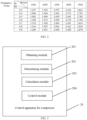
- the correspondence of the frequency of 30 Hz is shown in FIG. 2 .
- FIG. 2 when a current frequency is 30 Hz, a current power is 3000 W, and a current return air pressure is 0.7, an exhaust pressure by querying the table is 2.391 MPa.
- the return air parameter is the return gas pressure
- the first fitting formula is the pressure fitting formula
- the electrical parameter is the current
- Table 4 For example, ten coefficients of a compressor at a frequency of 30Hz are shown in Table 4 below (the current I and the return air pressure Pe are inputted for calculation): Table 4 A 1 0.166525 A 2 -1.33653 A 3 0.159364 A 4 2.590484 A 5 -0.07013 A 6 0.00455 A 7 -0.73553 A 8 -0.03958 A 9 0.004167 A 10 -0.00019
- the method further includes, prior to the operation at S2 of determining the first fitting formula corresponding to the first frequency from the preset calculation model: determining whether the calculation model includes the pressure fitting formula corresponding to the first frequency; and determining, in response to determining that the calculation model includes no pressure fitting formula corresponding to the first frequency, the exhaust pressure of the compressor by means of interpolation calculation.
- the exhaust pressure of the compressor is determined by means of interpolation calculation, which ensures the exhaust pressure of the compressor can be obtained at different frequencies.
- the action of determining the exhaust pressure of the compressor by means of the interpolation calculation may be implemented in the following manners: obtaining a second pressure fitting formula corresponding to a second frequency and a third pressure fitting formula corresponding to a third frequency from the calculation model (i.e.
- the second frequency being a frequency closest to the first frequency among the frequencies that correspond to the pressure fitting formulas that are greater than the first frequency
- the third frequency being a frequency closest to the first frequency among the frequencies that correspond to the pressure fitting formulas that are smaller than the first frequency (with this kind of frequency selection, the accuracy of the exhaust pressure by means of interpolation calculation can be improved); obtaining a second exhaust pressure and a third exhaust pressure by substituting the obtained electrical parameter and return air pressure of the compressor into each of the second pressure fitting formula and the third pressure fitting formula; and determining the exhaust pressure of the compressor based on the second exhaust pressure and the third exhaust pressure.
- an exhaust pressure for 45 Hz can be obtained by means of the interpolation.
- an exhaust pressure for 45 Hz can be obtained by means of linear interpolation between the exhaust pressure for 30 Hz and the exhaust pressure for 60 Hz.
- the return air parameter is a corresponding return air saturation temperature that is obtained based on a return air pressure during the operation of the compressor
- the first fitting formula is a temperature fitting formula
- the return air parameter includes a corresponding return air saturation temperature that is obtained based on a return air pressure during the operation of the compressor; and the first fitting formula includes a temperature fitting formula.
- Each different frequency has a temperature fitting formula corresponding thereto, i.e., different frequencies correspond to different temperature fitting formulas.
- Different frequencies herein corresponding to different temperature fitting formulas refers to the coefficients in the temperature fitting formulas corresponding to different frequencies are different, i.e., values of the ten coefficients B 1 to B 10 are different.
- the coefficient is fixed for a frequency of a compressor, and is obtained by fitting based on a massive amount of the historical experimental data of the compressor.
- the action of obtaining the exhaust pressure by inputting the electrical parameter and the return air parameter into the first fitting formula for calculation includes: obtaining the exhaust air saturation temperature by inputting the electrical parameter and the return air saturation temperature into the temperature fitting formula, and determining the exhaust pressure based on the obtained exhaust air saturation temperature.
- the exhaust pressure is determined based on the exhaust air saturation temperature, it has been described above that the pressure and the saturation temperature are in one-to-one correspondence, which is the inherent property of the refrigerant.
- Each refrigerant has the correspondence table, which can be directly obtained by querying Rcfprop.
- the correspondence table between the pressure and the saturation temperature can be pre-stored locally or in the cloud for subsequently querying the corresponding saturation temperature based on the pressure.
- the return air parameter is a corresponding return air saturation temperature that is obtained based on a return air pressure during the operation of the compressor
- the first fitting formula is a temperature fitting formula
- the electrical parameter is the power
- the above temperature fitting formula is obtained by fitting based on the historical power, the historical return air saturation temperature, and the historical frequency of the compressor.
- Each different frequency has a temperature fitting formula corresponding thereto, i.e., different frequencies correspond to different temperature fitting formulas.
- Different frequencies herein corresponding to different temperature fitting formulas refers to the coefficients in the temperature fitting formulas are different, i.e., values of the ten coefficients B 1 to B 10 are different.
- Table 5 For example, ten coefficients for a compressor at a frequency of 30 Hz are shown in Table 5 below (the power W and the return air saturation temperature Te are inputted for calculation ): Table 5 B 1 0.412209 B 2 0.037819 B 3 0.000333 B 4 0.00061 B 5 -0.000016 B 6 0.000000167 B 7 -0.000011 B 8 -0.00000013 B 9 0.00000000221 B 10 -0.000000000018
- the return air parameter is a corresponding return air saturation temperature that is obtained based on a return air pressure during the operation of the compressor
- the first fitting formula is a temperature fitting formula
- the electrical parameter is the power
- the exhaust pressure obtained in the action at block S3 can be corrected by using a temperature of a heat exchanger in the refrigeration system where the compressor is located, ensuring the accuracy in some special situations.
- the case where the exhaust pressure obtained in the action at block S3 is corrected by using the temperature of the heat exchanger will be described below.
- the method further includes, subsequent to the action of obtaining the exhaust pressure by inputting the electrical parameter and the return air parameter into the first fitting formula for calculation: obtaining a temperature Thx of a heat exchanger in a refrigeration system where the compressor is located is obtained, and obtaining a pressure P_cond of the heat exchanger based on the temperature Thx of the heat exchanger; obtaining pipeline pressure loss ⁇ P; and determining an ultimate exhaust pressure being a greater one between the obtained exhaust pressure and a sum (i.e., P_cond+ ⁇ P) of the pressure of the heat exchanger and the pipeline pressure loss.
- the temperature Thx of the heat exchanger is converted into the pressure P_cond of the heat exchanger by the linear fitting calculation formula or interpolation solution of the parameter table based on the physical property of the refrigerant.
- the temperature of the refrigerant is regarded as a saturated gaseous state, and the corresponding saturation pressure can be obtained by querying the table directly. It has been described above that the pressure and the saturation temperature are in one-to-one correspondence, which is the inherent property of the refrigerant.
- Each refrigerant has the correspondence table, which can be obtained by querying the Rcfprop directly.
- the correspondence table between the pressure and the saturation temperature can be pre-stored locally or in the cloud in this embodiment.
- the pipeline pressure loss ⁇ P is complex to be specifically calculated with great precision, but indeed can be roughly calculated based on the frequency, and a specific relational expression thereof is determined based on each system.
- the pipeline pressure loss ⁇ P is the coefficient multiplied by the compressor frequency, and the coefficient is manually set and may be 0.0007.
- the embodiments of the present disclosure have no specific limitation on the coefficient, and the coefficient may also be other values.
- the exhaust pressure obtained in the action at block S3 is basically equal to the actual exhaust pressure, but there is a situation where the calculated value is lower than the actual exhaust pressure. In this case, the use of P _ Cond + ⁇ P for calculation is more accurate.
- the compressor is controlled based on the exhaust pressure.
- the corresponding first fitting formula is determined based on the first frequency during the operation of the compressor, and the exhaust pressure is obtained by inputting the electrical parameter and the return air parameter during the operation of the compressor into the first fitting formula for calculation.
- the pressure sensor disposed on the exhaust side of the air conditioner can be omitted, i.e., the physical pressure sensor on the exhaust side is not needed, hence the cost is saved; or for the air conditioner with the pressure sensor disposed on the exhaust side, when the pressure sensor on the exhaust side is damaged, the above manner for calculation can be an alternative to obtaining the exhaust pressure, which ensures the user's normal use and thus improves the user experience.
- FIG. 3 illustrates the control apparatus 20 for the compressor using the method illustrated in FIG. 1 .
- the control apparatus 20 for the compressor includes at least one software function module that can be stored in a memory in a form of software or firmware or consolidate in an operating system of the control apparatus 20 for the compressor.
- FIG. 3 is a schematic diagram of a control apparatus for a compressor according to an embodiment of the present disclosure.
- the apparatus includes: an obtaining module 201 configured to obtain an electrical parameter, a return air parameter, and a first frequency of the compressor during operation of the compressor; a determining module 202 configured to determine a first fitting formula corresponding to the first frequency from a preset calculation model, the preset calculation model including fitting formulas corresponding to a plurality of frequencies, and each of the fitting formulas being obtained by fitting based on a historical electrical parameter, a historical return air parameter, and a historical frequency of the compressor; a calculation module 203 configured to obtain an exhaust pressure by inputting the electrical parameter and the return air parameter into the first fitting formula for calculation; and a control module 204 configured to control the compressor based on the exhaust pressure.
- the corresponding first fitting formula is determined based on the first frequency of the compressor during the operation of the compressor, and the exhaust pressure is obtained by inputting the electrical parameter and the return air parameter of the compressor during the operation of the compressor into the first fitting formula for calculation.
- the pressure sensor disposed on the exhaust side of the air conditioner can be omitted, i.e., the physical pressure sensor on the exhaust side is not needed, hence the cost is saved; or for the air conditioner with the pressure sensor disposed on the exhaust side, when the pressure sensor on the exhaust side is damaged, the above manner for calculation can be an alternative to obtaining the exhaust pressure, which ensures the user's normal use and thus improves the user experience.
- the return air parameter includes a return air pressure
- the first fitting formula includes a pressure fitting formula.
- the apparatus is further configured to: determine whether the calculation model includes the pressure fitting formula corresponding to the first frequency; and determine, in response to determining that the calculation model includes no pressure fitting formula corresponding to the first frequency, the exhaust pressure of the compressor by means of interpolation calculation.
- the apparatus is further configured to: obtain a second pressure fitting formula corresponding to a second frequency and a third pressure fitting formula corresponding to a third frequency from the calculation model, the second frequency being a frequency closest to the first frequency among the frequencies that correspond to the pressure fitting formulas that are greater than the first frequency, and the third frequency being a frequency closest to the first frequency among the frequencies that correspond to the pressure fitting formulas that are smaller than the first frequency; obtain a second exhaust pressure and a third exhaust pressure by substituting the obtained electrical parameter and return air pressure of the compressor into each of the second pressure fitting formula and the third pressure fitting formula; and determine the exhaust pressure of the compressor based on the second exhaust pressure and the third exhaust pressure.
- the return air parameter includes a corresponding return air saturation temperature that is obtained based on a return air pressure during the operation of the compressor; and the first fitting formula includes a temperature fitting formula.
- the apparatus is further configured to: obtain a temperature of a heat exchanger in a refrigeration system where the compressor is located, and obtain a pressure of the heat exchanger based on the temperature of the heat exchanger; obtain pipeline pressure loss; and determine a greater one between a sum of the pressure of the heat exchanger and the pipeline pressure loss and the obtained exhaust pressure as an ultimate exhaust pressure.
- the electrical parameter includes a power or a current.
- FIG. 4 is a schematic diagram of a control device for a compressor according to this embodiment.
- the device includes a memory 31 having computer-readable instructions stored thereon; a processor 32; and a communication bus 33 configured to implement connection communication between the memory 31 and the processor 32.
- the computer-readable instructions when executed by the processor 32, cause the processor 32 to perform the control method for the compressor according to the first embodiment, and details thereof are not repeated herein.
- control device for the compressor may further include more or fewer components than those illustrated in FIG. 4 , or have different configurations as illustrated in FIG. 4 .
- This embodiment of the present disclosure provides a non-volatile readable storage medium, e.g., a floppy disk, an optical disk, a hard disk, a flash memory, a USB flash disk, a Secure Digital Memory Card (SD), a Multimedia Card (MMC).
- the non-volatile readable storage medium has computer readable instructions stored thereon.
- the computer readable instructions when executed by the processor, cause the processor to perform the control method for the compressor according to the first embodiment, and details thereof are not repeated herein.
- This embodiment of the present disclosure provides a refrigeration system.
- the system includes: a compressor; the control apparatus for the compressor according to the second embodiment, or the control device for the compressor according to the third embodiment.
- the control apparatus or the control device is configured to control the compressor.
- the refrigeration system further includes: a pressure sensor configured to detect a return air pressure.
- the return air parameter includes the return air pressure or a corresponding return air saturation temperature that is obtained based on the return air pressure.
- the return air pressure is obtained by the pressure sensor, such that the calculation of the exhaust pressure is more accurate.
- the refrigeration system further includes a heat exchanger; and a temperature sensor configured to detect a temperature Thx of the heat exchanger.
- a pressure P_cond of the heat exchanger is obtained based on the temperature Thx of the heat exchanger; pipeline pressure loss is obtained; and a greater one between a sum (i.e., P_cond+ ⁇ P) of the pressure of the heat exchanger and the pipeline pressure loss and the obtained exhaust pressure is determined as an ultimate exhaust pressure.
- the refrigeration system includes an air conditioner.
- module and method may be implemented in other ways.
- the module embodiments described above are merely illustrative, for example, are merely divided according to logical functions, and can be divided in other ways in actual implementation.
- a plurality of modules or components may be combined or may be integrated into another terminal, or some features may be omitted.
- respective functional modules in respective embodiments of the present disclosure may be integrated to form an independent part, or the respective modules may be separate existence, or two or more modules may be integrated to form an independent part.
- mutual coupling or direct coupling or communication connection illustrated or discussed may be via some communication interfaces, or indirect coupling or communication connection of modules or units, which may be in an electrical, mechanical, or other form.
- the exhaust pressure can be obtained based on the calculation of the electrical parameter, the return air parameter, and the first frequency of the compressor during the operation of the compressor.
- the pressure sensor disposed on the exhaust side of the air conditioner can be omitted, hence the cost is saved; or for the air conditioner with the pressure sensor disposed on the exhaust side, when the pressure sensor on the exhaust side is damaged, the user can still use the air conditioner normally, thus the user experience is improved.
Landscapes
- Engineering & Computer Science (AREA)
- Physics & Mathematics (AREA)
- Mechanical Engineering (AREA)
- Thermal Sciences (AREA)
- General Engineering & Computer Science (AREA)
- Air Conditioning Control Device (AREA)
Abstract
Description
- The present application claims priority to
Chinese Patent Application No. 2021102333339, titled "CONTROL METHOD, APPARATUS, AND DEVICE FOR COMPRESSOR, STORAGE MEDIUM, AND REFRIGERATION SYSTEM, and filed on March 02, 2021 - The present disclosure relates to the field of refrigeration technologies, and more particularly, to a control method, apparatus, and device for a compressor, a storage medium, and a refrigeration system.
- Currently, in the refrigeration system, for example, in an air conditioner, data of an exhaust pressure of a compressor is required for controlling the compressor, and a physical pressure sensor is generally used to detect the exhaust pressure in practice. Once the pressure sensor malfunctions, it will take a long time to carry out maintenance, and a user cannot use the air conditioner in a case of an urgent necessity, thus user experience is poor.
- An object of embodiments of the present disclosure is to: provide a control method, apparatus, and device for a compressor, a storage medium, and a refrigeration system, aiming to solve the problem in the related art that since a physical pressure sensor is used to detect an exhaust pressure of a compressor, once the pressure sensor malfunctions, it will take a long time to carry out maintenance, and a user cannot use the air conditioner in a case of an urgent necessity, thus user experience is poor.
- To solve the above problem, the embodiments of the present disclosure can be implemented as follows.
- The embodiments of the present disclosure provide a control method for a compressor. The method includes: obtaining an electrical parameter, a return air parameter, and a first frequency of the compressor during operation of the compressor; determining a first fitting formula corresponding to the first frequency from a preset calculation model, the preset calculation model including fitting formulas corresponding to a plurality of frequencies, and each of the fitting formulas being obtained by fitting based on a historical electrical parameter, a historical return air parameter and a historical frequency of the compressor; obtaining an exhaust pressure by inputting the electrical parameter and the return air parameter into the first fitting formula for calculation; and controlling the compressor based on the exhaust pressure.
- With the above implementation, the corresponding first fitting formula is determined based on the first frequency during the operation of the compressor, and the exhaust pressure is obtained by inputting the electrical parameter and the return air parameter into the first fitting formula for calculation. In this way, the pressure sensor disposed on an exhaust side of the air conditioner can be omitted, i.e., a physical pressure sensor on the exhaust side is not needed, hence cost is saved; or for the air conditioner with the pressure sensor disposed on the exhaust side, when the pressure sensor on the exhaust side is damaged, the above manner for calculation can be an alternative to obtaining the exhaust pressure, which ensures a user's normal use and thus improves the user experience.
- Further, the return air parameter includes a return air pressure; and a first fitting formula includes a pressure fitting formula. The pressure fitting formula includes:


- With the above implementation, the exhaust pressure is obtained by using the electrical parameter, the return air pressure, the first frequency, and the above pressure fitting formula for calculation. In this way, the pressure sensor disposed on the exhaust side of the air conditioner can be omitted, i.e., the physical pressure sensor on the exhaust side is not needed, hence the cost is saved; or for the air conditioner with the pressure sensor disposed on the exhaust side, when the pressure sensor on the exhaust side is damaged, the above manner for calculation can be an alternative to obtaining the exhaust pressure, which ensures the user's normal use and thus improves the user experience.
- Further, the method further includes, prior to the operation of determining the first fitting formula corresponding to the first frequency from the preset calculation model: determining whether the calculation model includes the pressure fitting formula corresponding to the first frequency; and determining, in response to determining that the calculation model does not include pressure fitting formula corresponding to the first frequency, the exhaust pressure of the compressor by means of interpolation calculation.
- With the above implementation, for the case where the calculation model includes no pressure fitting formula corresponding to the first frequency, the exhaust pressure of the compressor is determined by means of the interpolation calculation, which ensures that the exhaust pressure of the compressor can be obtained at different frequencies.
- Further, the operation of determining the exhaust pressure of the compressor by means of the interpolation calculation includes: obtaining a second pressure fitting formula corresponding to a second frequency and a third pressure fitting formula corresponding to a third frequency from the calculation model, the second frequency being a frequency closest to the first frequency among the frequencies that correspond to the pressure fitting formulas that are greater than the first frequency, and the third frequency being a frequency closest to the first frequency among the frequencies that correspond to the pressure fitting formulas that are smaller than the first frequency; obtaining a second exhaust pressure and a third exhaust pressure by substituting the obtained electrical parameter and return air pressure of the compressor into each of the second pressure fitting formula and the third pressure fitting formula; and determining the exhaust pressure of the compressor based on the second exhaust pressure and the third exhaust pressure.
- Through the above manner, accuracy of the calculated value of the exhaust pressure is improved.
- Further, the return air parameter includes a corresponding return air saturation temperature that is obtained based on a return air pressure during the operation of the compressor; and the first fitting formula includes a temperature fitting formula. The temperature fitting formula includes:


- With the above implementation, the exhaust pressure is obtained by using the electrical parameter, the return air pressure, the first frequency, and the above pressure fitting formula for calculation. In this way, the pressure sensor disposed on the exhaust side of the air conditioner can be omitted, i.e., the physical pressure sensor on the exhaust side is not needed, hence the cost is saved; or for the air conditioner with the pressure sensor disposed on the exhaust side, when the pressure sensor on the exhaust side is damaged, the above manner for calculation can be an alternative to obtaining the exhaust pressure, which ensures the user's normal use and thus improves the user experience.
- Further, the method further includes, subsequent to the action of obtaining the exhaust pressure by inputting the electrical parameter and the return air parameter into the first fitting formula for calculation: obtaining a temperature of a heat exchanger in a refrigeration system where the compressor is located, and obtaining a pressure of the heat exchanger based on the temperature of the heat exchanger; obtaining pipeline pressure loss; and determining an ultimate exhaust pressure being a greater one between the obtained exhaust pressure and a sum of the pressure of the heat exchanger and the pipeline pressure loss.
- Through the above manner, the obtained exhaust pressure is corrected, which improves accuracy of an ultimate calculated value of the exhaust pressure.
- Further, the electrical parameter includes a power or a current.
- With the above implementation, the exhaust pressure is obtained by using the power or the current for calculation, such that a calculation is more precise.
- The embodiments of the present disclosure further provide a control apparatus for a compressor. The apparatus includes: an obtaining module configured to obtain an electrical parameter, a return air parameter, and a first frequency of the compressor during operation of the compressor; a determining module configured to determine a first fitting formula corresponding to the first frequency from a preset calculation model, the preset calculation model including fitting formulas corresponding to a plurality of frequencies, and each of the fitting formulas being obtained by fitting based on a historical electrical parameter, a historical return air parameter, and a historical frequency of the compressor; a calculation module configured to obtain an exhaust pressure by inputting the electrical parameter and the return air parameter into the first fitting formula for calculation; and a control module configured to control the compressor based on the exhaust pressure.
- With the above implementation, the corresponding first fitting formula is determined based on the first frequency of the compressor during the operation of the compressor, and the exhaust pressure is obtained by inputting the electrical parameter and the return air parameter into the first fitting formula for calculation. In this way, the pressure sensor disposed on the exhaust side of the air conditioner can be omitted, i.e., the physical pressure sensor on the exhaust side is not needed, the cost is saved; or for the air conditioner with the pressure sensor disposed on the exhaust side, when the pressure sensor on the exhaust side is damaged, the above manner for calculation can be an alternative to obtaining the exhaust pressure, which ensures the user's normal use and thus improves the user experience.
- The embodiments of the present disclosure further provide a control device for a compressor. The device includes: a memory having computer-readable instructions stored thereon; a processor; and a communication bus configured to implement connection communication between the memory and the processor. The computer-readable instructions, when executed by the processor, cause the processor to perform the control method for the compressor according to any one of the above embodiments.
- The embodiments of the present disclosure further provide a computer-readable storage medium. The computer-readable storage medium has a computer program stored thereon. The computer program, when executed by a processing device, performs the steps of the control method for the compressor according to any one of the above embodiments.
- The embodiments of the present disclosure further provide a refrigeration system. The refrigeration system includes: a compressor; and the above described control apparatus for the compressor, or the above described control device for the compressor. The control apparatus or the control device is configured to control the compressor.
- Further, the refrigeration system further includes: a pressure sensor configured to detect a return air pressure, the return air parameter including the return air pressure or a corresponding return air saturation temperature that is obtained based on the return air pressure.
- The return air pressure is obtained by the pressure sensor, such that the calculation of the exhaust pressure is more precise.
- Further, the refrigeration system further includes: a heat exchanger; and a temperature sensor configured to detect a temperature of the heat exchanger. A pressure of the heat exchanger is obtained based on the temperature of the heat exchanger; pipeline pressure loss is obtained; and a greater one between a sum of the pressure of the heat exchanger and the pipeline pressure loss and the obtained exhaust pressure is determined as an ultimate exhaust pressure.
- Through the above manner, the obtained exhaust pressure is corrected, which improves the accuracy of the ultimate calculated value of the exhaust pressure.
- Further, the refrigeration system further includes an air conditioner.
- In order to make the above objectives, features, and advantages of the present disclosure more comprehensible, the following detailed description of the preferred embodiments is described in detail below with reference to the drawings.
- In order to clearly explain technical solutions of embodiments of the present disclosure, drawings used in the embodiments are briefly described below. It should be understood that the drawings as described below merely illustrate some embodiments of the present disclosure, and should not be construed as limiting the scope. Based on these drawings, other drawings can be obtained by those skilled in the art without inventive effort.
-
FIG. 1 is a schematic diagram of a control method for a compressor according to an embodiment of the present disclosure. -
FIG. 2 is a schematic diagram of a correspondence table of a power, a return air pressure, and an exhaust pressure at a frequency of 30 Hz according to an embodiment of the present disclosure. -
FIG. 3 is a schematic diagram of a control apparatus for a compressor according to an embodiment of the present disclosure. -
FIG. 4 is a schematic diagram of a control device for a compressor according to an embodiment of the present disclosure. - The technical solutions in the embodiments of the present disclosure will be described below with reference to the accompanying drawings in the embodiments of the present disclosure.
- In the related art, since a physical pressure sensor is used to detect an exhaust pressure of a compressor, once the pressure sensor malfunctions, it will take a long time to carry out maintenance, and a user cannot use the air conditioner in a case of an urgent necessity, thus the user experience is poor. In addition, the price of the pressure sensor is relatively expensive, therefore overall cost of the air conditioner can be increased.
- To solve the above problems, the embodiments of the present disclosure provide a control method for a compressor. Referring to
FIG. 1, FIG. 1 is a schematic diagram of a control method for a compressor according to an embodiment of the present disclosure, which includes the following actions at block S 1, block S2, block S3, and block S4. - The air conditioner of this embodiment may be an air conditioner having a pressure sensor for detecting an exhaust pressure when leaving a factory. The method provided by this embodiment may be an alternative solution in a case of a failure of the physical pressure sensor (i.e., the exhaust pressure is obtained by means of the method provided by this embodiment), which may be a temporary alternative, or may be a long-term replacement. The air conditioner of this embodiment may also be an air conditioner that has no physical pressure sensor for detecting the exhaust pressure when leaving the factory, and the exhaust pressure is obtained during operation of the air conditioner by means of the method provided in this embodiment.
- At block S 1, an electrical parameter, a return air parameter, and a first frequency of the compressor are obtained during operation of the compressor.
- The electrical parameter includes a power or a current.
- The return air parameter includes a return air pressure or a corresponding return air saturation temperature that is obtained based on a return air pressure during the operation of the compressor. The pressure and the saturation temperature are in one-to-one correspondence, which is an inherent property of a refrigerant. Each refrigerant has a correspondence table, which can be obtained directly by querying Rcfprop (Rcfprop is a commonly used refrigerant physical property query software). The correspondence table between the pressure and the saturation temperature can be pre-stored locally or in a cloud for subsequently querying the corresponding saturation temperature based on the pressure.
- For example, a correspondence table of refrigerant R410A between the pressure of and the saturation temperature is shown in Table 1 below (it should be noted that numerical values in the embodiments of the present disclosure are merely examples for description, and do not constitute a specific limitation to the present disclosure ).
Table 1 Relative pressure MPa Saturation temperature °C 0.1 -36.84 0.2 -27.24 0.3 -19.87 0.4 -13.79 0.5 -8.58 0.6 -3.99 0.7 0.13 0.8 3.87 0.9 7.32 1 10.51 1.1 13.49 1.2 16.30 1.3 18.94 1.4 21.45 1.5 23.83 1.6 26.10 1.7 28.28 1.8 30.37 1.9 32.37 2 34.30 2.1 36.16 2.2 37.96 2.3 39.70 2.4 41.39 2.5 43.03 2.6 44.61 2.7 46.16 2.8 47.66 2.9 49.12 3 50.54 - Air enters the compressor from a return air port and is discharged from an exhaust port. The power and the current may be calculated or collected by a driving chip of the compressor. The return air pressure may be detected by the pressure sensor disposed on a return air side of the compressor, and the first frequency may be collected by the driving chip of the compressor.
- At block S2, a first fitting formula corresponding to the first frequency is determined from a preset calculation model. The preset calculation model includes fitting formulas corresponding to a plurality of frequencies, and each of the fitting formulas is obtained by fitting based on a historical electrical parameter, a historical return air parameter and a historical frequency of the compressor.
- At block S3, an exhaust pressure is obtained by inputting the electrical parameter and the return air parameter into the first fitting formula for calculation.
- In this embodiment, the calculation model is obtained in the following manners: the historical electrical parameter, the historical return air parameter, and the historical frequency of the compressor are obtained in advance; fitting is performed; and classification is performed based on different frequencies, each different frequency having a fitting formula corresponding thereto, i.e., different frequencies corresponding to different pressure fitting formulas. For example, frequency 1 corresponds to fitting formula 1, and
frequency 2 corresponds tofitting formula 2. After the electrical parameter, the return air parameter and the first frequency of the compressor during the operation of the compressor are obtained in the action at block S 1, the corresponding first fitting formula is determined based on the first frequency, and the exhaust pressure is obtained by inputting the electrical parameter and the return air parameter into the first fitting formula for calculation. - In this embodiment, the exhaust pressure may also be obtained in advance based on the calculation model; and then the correspondence table between the electrical parameter, the return air parameter, the frequency, and the exhaust pressure is stored; and when the electrical parameter, the return air parameter, the first frequency of the compressor during the operation of the compressor are obtained in the action at block S 1, the exhaust pressure is obtained directly by querying the stored correspondence table between the electrical parameter, the return air parameter, the frequency, and the exhaust pressure.
- The corresponding first fitting formula is determined based on the first frequency during the operation of the compressor, and the exhaust pressure is obtained by inputting the electrical parameter and the return air parameter during the operation of the processor into the first fitting formula for calculation. In this way, the pressure sensor disposed on the exhaust side of the air conditioner can be omitted, i.e., the physical pressure sensor on the exhaust side is not needed, cost is saved; or for the air conditioner with the pressure sensor disposed on the exhaust side, when the pressure sensor on the exhaust side is damaged, the above manner for calculation can be an alternative to obtaining the exhaust pressure, which ensures the user's normal use and thus improves the user experience.
- In this embodiment, the exhaust pressure may be obtained in advance based on the calculation model, and then the correspondence table between the electrical parameter, the return air parameter, the frequency and the exhaust pressure is stored, and when the first frequency, the electrical parameter and the return air parameter during the operation of the compressor are obtained in the action at block S1, the exhaust pressure is directly obtained by querying the table. After the first frequency, the electrical parameter, and the return air parameter during the operation of the compressor are obtained in the action at block S1, whether there is the corresponding exhaust pressure can be determined by querying the table, and if no exhaust pressure corresponding to the first frequency is stored in the correspondence table, the action at block S2 is performed.
- A case where the return air parameter is the return air pressure and the first fitting formula is the pressure fitting formula will be described below.
- In this embodiment, the return air parameter includes a return air pressure; and the first fitting formula includes a pressure fitting formula. The pressure fitting formula includes:


- Each different frequency has a pressure fitting formula corresponding thereto, i.e., different frequencies correspond to different pressure fitting formulas. Different frequencies herein corresponding to different pressure fitting formulas refers to values of the ten coefficients A1 to A10 in the pressure fitting formulas corresponding to different frequencies being different. The frequency is used for frequency segmentation. For a compressor, ten coefficients for different frequencies are different. The finer the segmentation, the more accurate the calculation. The coefficient is fixed for a frequency of a compressor, and is obtained by fitting based on a massive amount of historical experimental data of the compressor.
- In this embodiment, the electrical parameter includes a power or a current.
- A case where the return air parameter is the return air pressure, the first fitting formula is the pressure fitting formula, and the electrical parameter is the power will be described below.
- In an implementation, when the electrical parameter is a power W, i.e., X is the power W of the compressor, the pressure fitting formula includes:


- The above pressure fitting formula is obtained by fitting based on a historical power, a historical return air pressure and the historical frequency of the compressor. Each different frequency has a pressure fitting formula corresponding thereto, i.e., different frequencies correspond to different pressure fitting formulas. Different frequencies herein corresponding to different pressure fitting formulas refers to the coefficients in the pressure fitting formulas are different, i.e., values of the ten coefficients A1 to A10 are different.
- For example, ten coefficients for a compressor at a frequency of 30 Hz are shown in Table 2 below (the power W and the return air pressure Pe are inputted for calculation):
Table 2 A1 0.166525 A2 -1.33653 A3 0.000724 A4 2.590484 A5 -0.00032 A6 0.000000094 A7 -0.73553 A8 -0.00018 A9 0.0000000861 A10 -0.000000000018 - Ten coefficients for a compressor at a frequency of 60 Hz are shown in Table 3 below (the power W and the return air pressure Pe are inputted for calculation):
Table 3 A1 0.180344 A2 -1.34257 A3 0.000364 A4 2.58706 A5 -0.00016 A6 0.0000000232 A7 -0.73553 A8 -0.00009 A9 0.0000000215 A10 -0.0000000000022 - In this embodiment, the exhaust pressure may be obtained in advance based on the calculation model, and then the correspondence table between the frequency, the power, the return air pressure, and the exhaust pressure is stored, and when the first frequency, the power, and the return air pressure during the operation of the compressor are obtained in the action at block S1, the exhaust pressure is obtained by querying the table directly. For example, the correspondence of the frequency of 30 Hz is shown in
FIG. 2 . As shown inFIG. 2 , when a current frequency is 30 Hz, a current power is 3000 W, and a current return air pressure is 0.7, an exhaust pressure by querying the table is 2.391 MPa. - A case where the return air parameter is the return gas pressure, the first fitting formula is the pressure fitting formula, and the electrical parameter is the current will be described below.
- In an implementation, when the electrical parameter is a current I, i.e., when X is the current I of the compressor, the pressure fitting formula includes:


- For example, ten coefficients of a compressor at a frequency of 30Hz are shown in Table 4 below (the current I and the return air pressure Pe are inputted for calculation):
Table 4 A1 0.166525 A2 -1.33653 A3 0.159364 A4 2.590484 A5 -0.07013 A6 0.00455 A7 -0.73553 A8 -0.03958 A9 0.004167 A10 -0.00019 - A case where the calculation model includes no pressure fitting formula corresponding to the first frequency will be described below.
- In this embodiment, the method further includes, prior to the operation at S2 of determining the first fitting formula corresponding to the first frequency from the preset calculation model: determining whether the calculation model includes the pressure fitting formula corresponding to the first frequency; and determining, in response to determining that the calculation model includes no pressure fitting formula corresponding to the first frequency, the exhaust pressure of the compressor by means of interpolation calculation.
- With the above implementation, for the case where the calculation model includes no pressure fitting formula corresponding to the first frequency, i.e., the first frequency has no corresponding pressure fitting formula, the exhaust pressure of the compressor is determined by means of interpolation calculation, which ensures the exhaust pressure of the compressor can be obtained at different frequencies.
- In this embodiment, the action of determining the exhaust pressure of the compressor by means of the interpolation calculation (interpolation solution refers to linear interpolation calculation for each different frequency using an upper and lower limit frequency corresponding the frequency) may be implemented in the following manners: obtaining a second pressure fitting formula corresponding to a second frequency and a third pressure fitting formula corresponding to a third frequency from the calculation model (i.e. two existing frequencies and the corresponding pressure fitting formulas are obtained in advance from the calculation model), the second frequency being a frequency closest to the first frequency among the frequencies that correspond to the pressure fitting formulas that are greater than the first frequency, and the third frequency being a frequency closest to the first frequency among the frequencies that correspond to the pressure fitting formulas that are smaller than the first frequency (with this kind of frequency selection, the accuracy of the exhaust pressure by means of interpolation calculation can be improved); obtaining a second exhaust pressure and a third exhaust pressure by substituting the obtained electrical parameter and return air pressure of the compressor into each of the second pressure fitting formula and the third pressure fitting formula; and determining the exhaust pressure of the compressor based on the second exhaust pressure and the third exhaust pressure.
- For example, ten coefficients for frequency point of 30 Hz and ten coefficients for frequency point of 60 Hz are given to solve an exhaust pressure for 45 Hz. As long as the exhaust pressure for 30 Hz and the exhaust pressure for 60 Hz are obtained first, an exhaust pressure for 45 Hz can be obtained by means of the interpolation. In some embodiments, an exhaust pressure for 45 Hz can be obtained by means of linear interpolation between the exhaust pressure for 30 Hz and the exhaust pressure for 60 Hz.
- Through the above manner, the accuracy of the calculated value of the exhaust pressure is improved.
- A case where the return air parameter is a corresponding return air saturation temperature that is obtained based on a return air pressure during the operation of the compressor, and the first fitting formula is a temperature fitting formula will be described below.
- In this embodiment, the return air parameter includes a corresponding return air saturation temperature that is obtained based on a return air pressure during the operation of the compressor; and the first fitting formula includes a temperature fitting formula. The temperature fitting formula includes:


Tc=B1+B2*Te+B3*X+B4*Te2+B5*Te*X+B6*X2+B7*Te3+B8*Te2*X +B9*Te*X2+B10*X3, where Tc represents an exhaust air saturation temperature of the compressor, Tc represents the return air saturation temperature of the compressor, X represents the electrical parameter of the compressor, and B1 to B10 represent coefficients of the temperature fitting formula. - Each different frequency has a temperature fitting formula corresponding thereto, i.e., different frequencies correspond to different temperature fitting formulas. Different frequencies herein corresponding to different temperature fitting formulas refers to the coefficients in the temperature fitting formulas corresponding to different frequencies are different, i.e., values of the ten coefficients B1 to B10 are different. The coefficient is fixed for a frequency of a compressor, and is obtained by fitting based on a massive amount of the historical experimental data of the compressor.
- The action of obtaining the exhaust pressure by inputting the electrical parameter and the return air parameter into the first fitting formula for calculation includes: obtaining the exhaust air saturation temperature by inputting the electrical parameter and the return air saturation temperature into the temperature fitting formula, and determining the exhaust pressure based on the obtained exhaust air saturation temperature. When the exhaust pressure is determined based on the exhaust air saturation temperature, it has been described above that the pressure and the saturation temperature are in one-to-one correspondence, which is the inherent property of the refrigerant. Each refrigerant has the correspondence table, which can be directly obtained by querying Rcfprop. The correspondence table between the pressure and the saturation temperature can be pre-stored locally or in the cloud for subsequently querying the corresponding saturation temperature based on the pressure.
- A case where the return air parameter is a corresponding return air saturation temperature that is obtained based on a return air pressure during the operation of the compressor, the first fitting formula is a temperature fitting formula, and the electrical parameter is the power will be described below.
- In an implementation, when the electrical parameter is the power W, i.e., the X is the power W of the compressor, the temperature fitting formula includes:


- The above temperature fitting formula is obtained by fitting based on the historical power, the historical return air saturation temperature, and the historical frequency of the compressor. Each different frequency has a temperature fitting formula corresponding thereto, i.e., different frequencies correspond to different temperature fitting formulas. Different frequencies herein corresponding to different temperature fitting formulas refers to the coefficients in the temperature fitting formulas are different, i.e., values of the ten coefficients B1 to B10 are different.
- For example, ten coefficients for a compressor at a frequency of 30 Hz are shown in Table 5 below (the power W and the return air saturation temperature Te are inputted for calculation ):
Table 5 B1 0.412209 B2 0.037819 B3 0.000333 B4 0.00061 B5 -0.000016 B6 0.000000167 B7 -0.000011 B8 -0.00000013 B9 0.00000000221 B10 -0.000000000018 - A case where the return air parameter is a corresponding return air saturation temperature that is obtained based on a return air pressure during the operation of the compressor, the first fitting formula is a temperature fitting formula, and the electrical parameter is the power will be described below.
- In an implementation, when the electrical parameter is the current I, i.e., the X is the current I of the compressor, the temperature fitting formula includes:


- Examples thereof will not be described herein.
- In this embodiment, the exhaust pressure obtained in the action at block S3 can be corrected by using a temperature of a heat exchanger in the refrigeration system where the compressor is located, ensuring the accuracy in some special situations. The case where the exhaust pressure obtained in the action at block S3 is corrected by using the temperature of the heat exchanger will be described below.
- In this embodiment, at block S3, the method further includes, subsequent to the action of obtaining the exhaust pressure by inputting the electrical parameter and the return air parameter into the first fitting formula for calculation: obtaining a temperature Thx of a heat exchanger in a refrigeration system where the compressor is located is obtained, and obtaining a pressure P_cond of the heat exchanger based on the temperature Thx of the heat exchanger; obtaining pipeline pressure loss ΔP; and determining an ultimate exhaust pressure being a greater one between the obtained exhaust pressure and a sum (i.e., P_cond+△P) of the pressure of the heat exchanger and the pipeline pressure loss.
- The temperature Thx of the heat exchanger is converted into the pressure P_cond of the heat exchanger by the linear fitting calculation formula or interpolation solution of the parameter table based on the physical property of the refrigerant. The temperature of the refrigerant is regarded as a saturated gaseous state, and the corresponding saturation pressure can be obtained by querying the table directly. It has been described above that the pressure and the saturation temperature are in one-to-one correspondence, which is the inherent property of the refrigerant. Each refrigerant has the correspondence table, which can be obtained by querying the Rcfprop directly. The correspondence table between the pressure and the saturation temperature can be pre-stored locally or in the cloud in this embodiment.
- The pipeline pressure loss ΔP is complex to be specifically calculated with great precision, but indeed can be roughly calculated based on the frequency, and a specific relational expression thereof is determined based on each system. For example, the pipeline pressure loss ΔP is the coefficient multiplied by the compressor frequency, and the coefficient is manually set and may be 0.0007. The embodiments of the present disclosure have no specific limitation on the coefficient, and the coefficient may also be other values.
- Generally, the exhaust pressure obtained in the action at block S3 is basically equal to the actual exhaust pressure, but there is a situation where the calculated value is lower than the actual exhaust pressure. In this case, the use of P _ Cond + ΔP for calculation is more accurate.
- At block S4, the compressor is controlled based on the exhaust pressure.
- With the implementation of this embodiment, the corresponding first fitting formula is determined based on the first frequency during the operation of the compressor, and the exhaust pressure is obtained by inputting the electrical parameter and the return air parameter during the operation of the compressor into the first fitting formula for calculation. In this way, the pressure sensor disposed on the exhaust side of the air conditioner can be omitted, i.e., the physical pressure sensor on the exhaust side is not needed, hence the cost is saved; or for the air conditioner with the pressure sensor disposed on the exhaust side, when the pressure sensor on the exhaust side is damaged, the above manner for calculation can be an alternative to obtaining the exhaust pressure, which ensures the user's normal use and thus improves the user experience.
- Based on the same inventive concept, an embodiment of the present disclosure provides a
control apparatus 20 for a compressor. Referring toFIG. 3, FIG. 3 illustrates thecontrol apparatus 20 for the compressor using the method illustrated inFIG. 1 . It should be understood that the specific function of thecontrol apparatus 20 for the compressor may refer to the description above, and details thereof is omitted herein to avoid repetition. Thecontrol apparatus 20 for the compressor includes at least one software function module that can be stored in a memory in a form of software or firmware or consolidate in an operating system of thecontrol apparatus 20 for the compressor. -
FIG. 3 is a schematic diagram of a control apparatus for a compressor according to an embodiment of the present disclosure. The apparatus includes: an obtainingmodule 201 configured to obtain an electrical parameter, a return air parameter, and a first frequency of the compressor during operation of the compressor; a determiningmodule 202 configured to determine a first fitting formula corresponding to the first frequency from a preset calculation model, the preset calculation model including fitting formulas corresponding to a plurality of frequencies, and each of the fitting formulas being obtained by fitting based on a historical electrical parameter, a historical return air parameter, and a historical frequency of the compressor; acalculation module 203 configured to obtain an exhaust pressure by inputting the electrical parameter and the return air parameter into the first fitting formula for calculation; and acontrol module 204 configured to control the compressor based on the exhaust pressure. - With the implementation of this embodiment, the corresponding first fitting formula is determined based on the first frequency of the compressor during the operation of the compressor, and the exhaust pressure is obtained by inputting the electrical parameter and the return air parameter of the compressor during the operation of the compressor into the first fitting formula for calculation. In this way, the pressure sensor disposed on the exhaust side of the air conditioner can be omitted, i.e., the physical pressure sensor on the exhaust side is not needed, hence the cost is saved; or for the air conditioner with the pressure sensor disposed on the exhaust side, when the pressure sensor on the exhaust side is damaged, the above manner for calculation can be an alternative to obtaining the exhaust pressure, which ensures the user's normal use and thus improves the user experience.
- In an embodiment, the return air parameter includes a return air pressure; and the first fitting formula includes a pressure fitting formula. The pressure fitting formula includes:


Pc=A1+A2*Pe+A3*X+A4*Pe2+A5*Pe*X+A6*X2+A7*Pe3+A8*Pe2*X+A9*Pe*X2 +A10*X3, where Pc represents the exhaust pressure of the compressor, Pe represents the return air pressure of the compressor, X represents the electrical parameter of the compressor, and A1 to A10 represent coefficients of the pressure fitting formula. - In an embodiment, the apparatus is further configured to: determine whether the calculation model includes the pressure fitting formula corresponding to the first frequency; and determine, in response to determining that the calculation model includes no pressure fitting formula corresponding to the first frequency, the exhaust pressure of the compressor by means of interpolation calculation.
- In an embodiment, the apparatus is further configured to: obtain a second pressure fitting formula corresponding to a second frequency and a third pressure fitting formula corresponding to a third frequency from the calculation model, the second frequency being a frequency closest to the first frequency among the frequencies that correspond to the pressure fitting formulas that are greater than the first frequency, and the third frequency being a frequency closest to the first frequency among the frequencies that correspond to the pressure fitting formulas that are smaller than the first frequency; obtain a second exhaust pressure and a third exhaust pressure by substituting the obtained electrical parameter and return air pressure of the compressor into each of the second pressure fitting formula and the third pressure fitting formula; and determine the exhaust pressure of the compressor based on the second exhaust pressure and the third exhaust pressure.
- In an embodiment, the return air parameter includes a corresponding return air saturation temperature that is obtained based on a return air pressure during the operation of the compressor; and the first fitting formula includes a temperature fitting formula. The temperature fitting formula includes:


Tc=B1+B2*Te+B3*X+B4*Te2+B5*Te*X+B6*X2+B7*Te3+B8*Te2*X+B9*Te*X2 +B10*X3, where Tc represents an exhaust air saturation temperature of the compressor, Tc represents the return air saturation temperature of the compressor, X represents the electrical parameter of the compressor, and Bi to B10 represent coefficients of the temperature fitting formula. Thecalculation module 203 is further configured to: obtain the exhaust air saturation temperature by inputting the electrical parameter and the return air saturation temperature into the temperature fitting formula, and determine the exhaust pressure based on the obtained exhaust air saturation temperature. - In an embodiment, the apparatus is further configured to: obtain a temperature of a heat exchanger in a refrigeration system where the compressor is located, and obtain a pressure of the heat exchanger based on the temperature of the heat exchanger; obtain pipeline pressure loss; and determine a greater one between a sum of the pressure of the heat exchanger and the pipeline pressure loss and the obtained exhaust pressure as an ultimate exhaust pressure.
- In an embodiment, the electrical parameter includes a power or a current.
- It should be understood that, for the sake of a concise description, some of the content described in the first embodiment will not be repeated in this embodiment.
- This embodiment of the present disclosure provides a control device for a compressor. Referring to
FIG. 4, FIG. 4 is a schematic diagram of a control device for a compressor according to this embodiment. The device includes amemory 31 having computer-readable instructions stored thereon; aprocessor 32; and acommunication bus 33 configured to implement connection communication between thememory 31 and theprocessor 32. The computer-readable instructions, when executed by theprocessor 32, cause theprocessor 32 to perform the control method for the compressor according to the first embodiment, and details thereof are not repeated herein. - It can be understood that the structure illustrated in
FIG. 4 is merely exemplary, and the control device for the compressor may further include more or fewer components than those illustrated inFIG. 4 , or have different configurations as illustrated inFIG. 4 . - This embodiment of the present disclosure provides a non-volatile readable storage medium, e.g., a floppy disk, an optical disk, a hard disk, a flash memory, a USB flash disk, a Secure Digital Memory Card (SD), a Multimedia Card (MMC). The non-volatile readable storage medium has computer readable instructions stored thereon. The computer readable instructions, when executed by the processor, cause the processor to perform the control method for the compressor according to the first embodiment, and details thereof are not repeated herein.
- This embodiment of the present disclosure provides a refrigeration system. The system includes: a compressor; the control apparatus for the compressor according to the second embodiment, or the control device for the compressor according to the third embodiment. The control apparatus or the control device is configured to control the compressor.
- In an embodiment, in this embodiment, the refrigeration system further includes: a pressure sensor configured to detect a return air pressure. The return air parameter includes the return air pressure or a corresponding return air saturation temperature that is obtained based on the return air pressure.
- The return air pressure is obtained by the pressure sensor, such that the calculation of the exhaust pressure is more accurate.
- In an embodiment, the refrigeration system further includes a heat exchanger; and a temperature sensor configured to detect a temperature Thx of the heat exchanger. A pressure P_cond of the heat exchanger is obtained based on the temperature Thx of the heat exchanger; pipeline pressure loss is obtained; and a greater one between a sum (i.e., P_cond+△P) of the pressure of the heat exchanger and the pipeline pressure loss and the obtained exhaust pressure is determined as an ultimate exhaust pressure.
- Through the above manner, the obtained exhaust pressure is corrected, which improves the accuracy of the ultimate calculated value of the exhaust pressure.
- In this embodiment, the refrigeration system includes an air conditioner.
- In the embodiments provided by the present disclosure, it should be understood that, the disclosed module and method may be implemented in other ways. The module embodiments described above are merely illustrative, for example, are merely divided according to logical functions, and can be divided in other ways in actual implementation. For example, a plurality of modules or components may be combined or may be integrated into another terminal, or some features may be omitted. For example, respective functional modules in respective embodiments of the present disclosure may be integrated to form an independent part, or the respective modules may be separate existence, or two or more modules may be integrated to form an independent part.
- In addition, the mutual coupling or direct coupling or communication connection illustrated or discussed may be via some communication interfaces, or indirect coupling or communication connection of modules or units, which may be in an electrical, mechanical, or other form.
- In this disclosure, the relational terms herein, such as "first" and "second", are used only for differentiating one entity or operation, from another entity or operation, without necessarily requiring or implying that there should be any actual relationship or sequence among the entities or operations.
- While the embodiments of the present disclosure have been described above, they are not intended to limit the present disclosure. For those skilled in the art, various changes and variations can be made to the present disclosure. Any modifications, equivalent replacement, and improvements made within the spirit and principle of the present disclosure are to be encompassed by the scope of the claims of the present disclosure.
- In the control method, apparatus, and device for the compressor, the storage medium, and the refrigeration system provided in the embodiments of the present disclosure, the exhaust pressure can be obtained based on the calculation of the electrical parameter, the return air parameter, and the first frequency of the compressor during the operation of the compressor. In this way, the pressure sensor disposed on the exhaust side of the air conditioner can be omitted, hence the cost is saved; or for the air conditioner with the pressure sensor disposed on the exhaust side, when the pressure sensor on the exhaust side is damaged, the user can still use the air conditioner normally, thus the user experience is improved.
Claims (15)
- A control method for a compressor, characterized in comprising:obtaining an electrical parameter, a return air parameter, and a first frequency of the compressor during operation of the compressor;determining a first fitting formula corresponding to the first frequency from a preset calculation model, wherein the preset calculation model comprises fitting formulas corresponding to a plurality of frequencies, and wherein each of the fitting formulas is obtained by fitting based on a historical electrical parameter, a historical return air parameter and a historical frequency of the compressor;obtaining an exhaust pressure by inputting the electrical parameter and the return air parameter into the first fitting formula for calculation; andcontrolling the compressor based on the exhaust pressure.
- The method according to claim 1, characterized in that:the return air parameter comprises a return air pressure; anda first fitting formula comprises a pressure fitting formula, the pressure fitting formula comprising:


- The method according to claim 2, characterized in further comprising, prior to the operation of determining the first fitting formula corresponding to the first frequency from the preset calculation model:determining whether the calculation model comprises the pressure fitting formula corresponding to the first frequency; anddetermining, in response to determining that the calculation model does not comprise pressure fitting formula corresponding to the first frequency, the exhaust pressure of the compressor by means of interpolation calculation.
- The method according to claim 3, characterized in that said determining the exhaust pressure of the compressor by means of the interpolation calculation comprises:obtaining a second pressure fitting formula corresponding to a second frequency and a third pressure fitting formula corresponding to a third frequency from the calculation model, the second frequency being a frequency closest to the first frequency among the frequencies that correspond to the pressure fitting formulas that are greater than the first frequency, and the third frequency being a frequency closest to the first frequency among the frequencies that correspond to the pressure fitting formulas that are smaller than the first frequency;obtaining a second exhaust pressure and a third exhaust pressure by substituting the obtained electrical parameter and return air pressure of the compressor into each of the second pressure fitting formula and the third pressure fitting formula; anddetermining the exhaust pressure of the compressor based on the second exhaust pressure and the third exhaust pressure.
- The method according to any one of claims 1 to 4, characterized in that:the return air parameter comprises a corresponding return air saturation temperature that is obtained based on the return air pressure during the operation of the compressor; andthe first fitting formula comprises a temperature fitting formula, the temperature fitting formula comprising:

 said obtaining the exhaust pressure by inputting the electrical parameter and the return air parameter into the first fitting formula for calculation comprises: obtaining the exhaust air saturation temperature by inputting the electrical parameter and the return air saturation temperature into the temperature fitting formula, and determining the exhaust pressure based on the obtained exhaust air saturation temperature.
 - The method according to claim 5, characterized in that said determining the exhaust pressure based on the obtained exhaust air saturation temperature comprises:
determining an exhaust pressure corresponding to the obtained exhaust air saturation temperature based on a pre-stored correspondence table between the pressure and the saturation temperature. - The method according to any one of claims 1 to 6, characterized in further comprising, subsequent to said obtaining the exhaust pressure by inputting the electrical parameter and the return air parameter into the first fitting formula for calculation:obtaining a temperature of a heat exchanger in a refrigeration system where the compressor is located, and obtaining a pressure of the heat exchanger based on the temperature of the heat exchanger;obtaining a pipeline pressure loss; anddetermining an ultimate exhaust pressure being a greater one between the obtained exhaust pressure and a sum of the pressure of the heat exchanger and the pipeline pressure loss.
- The method according to any one of claims 1 to 7, characterized in that the electrical parameter comprises a power or a current.
- A control apparatus for a compressor, characterized in that the control apparatus comprises:an obtaining module configured to obtain an electrical parameter, a return air parameter, and a first frequency of the compressor during operation of the compressor;a determining module configured to determine a first fitting formula corresponding to the first frequency from a preset calculation model, wherein the preset calculation model comprises fitting formulas corresponding to a plurality of frequencies, and wherein each of the fitting formulas is obtained by fitting based on a historical electrical parameter, a historical return air parameter, and a historical frequency of the compressor;a calculation module configured to obtain an exhaust pressure by inputting the electrical parameter and the return air parameter into the first fitting formula for calculation; anda control module configured to control the compressor based on the exhaust pressure.
- A control device for a compressor, characterized in that the control device comprises:a memory having a computer-readable instructions stored thereon;a processor; anda communication bus configured to implement connection communication between the memory and the processor, wherein the computer-readable instruction, when executed by the processor, causes the processor to perform a control method for a compressor according to any one of claims 1 to 8.
- A computer-readable storage medium, having a computer program stored thereon, characterized in that the computer program, when executed by a processing device, performs steps of a control method for a compressor according to any one of claims 1 to 8.
- A refrigeration system, characterized in comprising:a compressor; anda control apparatus for the compressor according to claim 9, or a control device for a compressor according to claim 10, wherein the control apparatus or the control device is configured to control the compressor.
- The refrigeration system according to claim 12, characterized in further comprising:
a pressure sensor configured to detect a return air pressure, a return air parameter comprising the return air pressure or a corresponding return air saturation temperature that is obtained based on the return air pressure. - The refrigeration system according to claim 12 or 13, characterized in further comprising:a heat exchanger; anda temperature sensor configured to detect a temperature of the heat exchanger, whereina pressure of the heat exchanger is obtained based on the temperature of the heat exchanger;a pipeline pressure loss is obtained; anda greater one between a sum of the pressure of the heat exchanger and the pipeline pressure loss and an obtained exhaust pressure is determined as an ultimate exhaust pressure.
- The refrigeration system according to any one of claims 12 to 14, characterized in further comprising: an air conditioner.
Applications Claiming Priority (2)
| Application Number | Priority Date | Filing Date | Title |
|---|---|---|---|
| CN202110233333.9A CN114992925A (en) | 2021-03-02 | 2021-03-02 | Control method, device and equipment of compressor, storage medium and refrigeration system |
| PCT/CN2021/121837 WO2022183725A1 (en) | 2021-03-02 | 2021-09-29 | Control method for compressor, apparatus, device, storage medium, and cooling system |
Publications (2)
| Publication Number | Publication Date |
|---|---|
| EP4286775A1 true EP4286775A1 (en) | 2023-12-06 |
| EP4286775A4 EP4286775A4 (en) | 2024-05-01 |
Family
ID=83018728
Family Applications (1)
| Application Number | Title | Priority Date | Filing Date |
|---|---|---|---|
| EP21928799.2A Pending EP4286775A4 (en) | 2021-03-02 | 2021-09-29 | CONTROL METHOD FOR COMPRESSOR, APPARATUS, DEVICE, STORAGE MEDIUM AND COOLING SYSTEM |
Country Status (4)
| Country | Link |
|---|---|
| US (1) | US20240230195A9 (en) |
| EP (1) | EP4286775A4 (en) |
| CN (1) | CN114992925A (en) |
| WO (1) | WO2022183725A1 (en) |
Families Citing this family (2)
| Publication number | Priority date | Publication date | Assignee | Title |
|---|---|---|---|---|
| CN116428715A (en) * | 2023-03-31 | 2023-07-14 | 青岛海尔空调电子有限公司 | Air conditioner control method and air conditioner |
| CN116593194A (en) * | 2023-05-08 | 2023-08-15 | 南京天加环境科技有限公司 | A multi-connected virtual sensor data correction method based on big data, air conditioner and storage medium |
Family Cites Families (15)
| Publication number | Priority date | Publication date | Assignee | Title |
|---|---|---|---|---|
| JP3849468B2 (en) * | 2001-07-11 | 2006-11-22 | 松下電器産業株式会社 | Air conditioner |
| JP2005009794A (en) * | 2003-06-20 | 2005-01-13 | Sanden Corp | Refrigeration cycle controller |
| US20120177514A1 (en) * | 2011-01-12 | 2012-07-12 | Hahn Gregory W | Discharge pressure estimation for compressor |
| CN103032996B (en) * | 2012-12-12 | 2015-03-11 | 宁波奥克斯电气有限公司 | Parallel compressor matching method for preventing compressor from being started and stopped frequently |
| CN104896647B (en) * | 2014-03-03 | 2018-03-20 | 合肥海尔空调器有限公司 | The anti-cold air control method and system of indoor apparatus of air conditioner |
| US11181291B2 (en) * | 2016-11-01 | 2021-11-23 | Ecoer Inc. | DC varaiable speed compressor control method and control system |
| CN108009382B (en) * | 2017-12-25 | 2021-09-24 | 沈阳鼓风机集团股份有限公司 | Centrifugal Compressor Design System |
| CN108197407B (en) * | 2018-01-29 | 2021-10-22 | 上海交通大学 | A Performance Calculation Method of Inverter Air Supply Compressor Based on Local Linearization Theory |
| CN109406042B (en) * | 2018-10-24 | 2021-02-09 | 四川长虹空调有限公司 | Pressure data fitting method for variable frequency air conditioner |
| CN109408963B (en) * | 2018-10-25 | 2022-06-21 | 四川长虹空调有限公司 | Fitting method for piping vibration response function relation of air conditioner under different environmental working conditions |
| CN113167506B (en) * | 2018-12-06 | 2022-07-15 | 三菱电机株式会社 | Refrigeration cycle device |
| JP6911883B2 (en) * | 2019-03-29 | 2021-07-28 | ダイキン工業株式会社 | Performance deterioration diagnosis system for refrigeration cycle equipment |
| CN110736200A (en) * | 2019-09-25 | 2020-01-31 | 青岛海尔空调器有限总公司 | Control method and control device for air conditioner and air conditioner |
| CN111578472B (en) * | 2020-05-29 | 2022-03-22 | 广东美的制冷设备有限公司 | Control method and device of air conditioner outdoor unit, air conditioner outdoor unit and air conditioner |
| CN112484348A (en) * | 2020-11-12 | 2021-03-12 | 珠海格力电器股份有限公司 | Control method and device of electronic expansion valve and electrical equipment |
-
2021
- 2021-03-02 CN CN202110233333.9A patent/CN114992925A/en active Pending
- 2021-09-29 US US18/548,496 patent/US20240230195A9/en active Pending
- 2021-09-29 WO PCT/CN2021/121837 patent/WO2022183725A1/en not_active Ceased
- 2021-09-29 EP EP21928799.2A patent/EP4286775A4/en active Pending
Also Published As
| Publication number | Publication date |
|---|---|
| US20240133606A1 (en) | 2024-04-25 |
| US20240230195A9 (en) | 2024-07-11 |
| CN114992925A (en) | 2022-09-02 |
| EP4286775A4 (en) | 2024-05-01 |
| WO2022183725A1 (en) | 2022-09-09 |
Similar Documents
| Publication | Publication Date | Title |
|---|---|---|
| US7308384B2 (en) | Ordered record of system-wide fault in an HVAC system | |
| US7212887B2 (en) | Service and diagnostic tool for HVAC systems | |
| EP2604933A1 (en) | Heating, ventilation and air conditioning system user interface having a one-touch away feature and method of operation thereof | |
| EP3470749B1 (en) | Method and apparatus for controlling electric heating of air conditioner compressor | |
| CN110986244B (en) | Air conditioner pipeline detection method and device, storage medium, terminal and air conditioner | |
| US20240230195A9 (en) | Control method, apparatus, and device for compressor, storage medium, and refrigeration system | |
| WO2020248764A1 (en) | Control method for air conditioning system, air conditioning control system, and air conditioning system | |
| EP4541613A1 (en) | Vehicle air conditioning system remote diagnosis method and system, platform and storage medium | |
| US11625080B2 (en) | Electronic apparatus, fan control method, and recording medium | |
| WO2024207857A1 (en) | Method and device for controlling air conditioner, and air conditioner and storage medium | |
| CN111190412B (en) | Fault analysis method and device, storage medium and terminal | |
| CN218413261U (en) | Dual-redundancy feedback control system | |
| CN115218432B (en) | Air conditioning control method, air conditioning and medium | |
| CN108489164A (en) | Control method and device of electronic expansion valve and electronic equipment | |
| CN113971101B (en) | Method, device, storage medium and system for diagnosing temperature faults of server | |
| CN104198203A (en) | Method and device for detecting operation of air-conditioners | |
| CN115540200B (en) | Method and device for detecting refrigerant abnormality, air conditioner and storage medium | |
| CN113241568B (en) | Method for connecting electromechanical devices | |
| CN201594788U (en) | Inverter operation panel with parameter storage and Chinese character display function | |
| JP2019191739A (en) | Selection support system and selection support method | |
| JPH04258740A (en) | Power plant performance diagnostic device | |
| CN115406089A (en) | Pressure difference detection method of compressor, air conditioner and computer readable storage medium | |
| JP2007263546A (en) | Refrigerator equipment operation method and equipment comprising a refrigerator | |
| CN215295448U (en) | Evaporator device and air conditioner unit | |
| CN222883058U (en) | IC card detection device |
Legal Events
| Date | Code | Title | Description |
|---|---|---|---|
| STAA | Information on the status of an ep patent application or granted ep patent |
Free format text: STATUS: THE INTERNATIONAL PUBLICATION HAS BEEN MADE |
|
| PUAI | Public reference made under article 153(3) epc to a published international application that has entered the european phase |
Free format text: ORIGINAL CODE: 0009012 |
|
| STAA | Information on the status of an ep patent application or granted ep patent |
Free format text: STATUS: REQUEST FOR EXAMINATION WAS MADE |
|
| 17P | Request for examination filed |
Effective date: 20230901 |
|
| AK | Designated contracting states |
Kind code of ref document: A1 Designated state(s): AL AT BE BG CH CY CZ DE DK EE ES FI FR GB GR HR HU IE IS IT LI LT LU LV MC MK MT NL NO PL PT RO RS SE SI SK SM TR |
|
| A4 | Supplementary search report drawn up and despatched |
Effective date: 20240404 |
|
| RIC1 | Information provided on ipc code assigned before grant |
Ipc: F25B 49/02 20060101AFI20240327BHEP |
|
| DAV | Request for validation of the european patent (deleted) | ||
| DAX | Request for extension of the european patent (deleted) | ||
| STAA | Information on the status of an ep patent application or granted ep patent |
Free format text: STATUS: EXAMINATION IS IN PROGRESS |
|
| 17Q | First examination report despatched |
Effective date: 20260224 |