EP4286742B1 - Automotive lighting and/or signaling device with a light guide - Google Patents
Automotive lighting and/or signaling device with a light guide Download PDFInfo
- Publication number
- EP4286742B1 EP4286742B1 EP22176412.9A EP22176412A EP4286742B1 EP 4286742 B1 EP4286742 B1 EP 4286742B1 EP 22176412 A EP22176412 A EP 22176412A EP 4286742 B1 EP4286742 B1 EP 4286742B1
- Authority
- EP
- European Patent Office
- Prior art keywords
- lighting
- signaling device
- light
- light guide
- polyline
- Prior art date
- Legal status (The legal status is an assumption and is not a legal conclusion. Google has not performed a legal analysis and makes no representation as to the accuracy of the status listed.)
- Active
Links
Images


Classifications
-
- F—MECHANICAL ENGINEERING; LIGHTING; HEATING; WEAPONS; BLASTING
- F21—LIGHTING
- F21S—NON-PORTABLE LIGHTING DEVICES; SYSTEMS THEREOF; VEHICLE LIGHTING DEVICES SPECIALLY ADAPTED FOR VEHICLE EXTERIORS
- F21S43/00—Signalling devices specially adapted for vehicle exteriors, e.g. brake lamps, direction indicator lights or reversing lights
- F21S43/10—Signalling devices specially adapted for vehicle exteriors, e.g. brake lamps, direction indicator lights or reversing lights characterised by the light source
- F21S43/13—Signalling devices specially adapted for vehicle exteriors, e.g. brake lamps, direction indicator lights or reversing lights characterised by the light source characterised by the type of light source
- F21S43/14—Light emitting diodes [LED]
-
- F—MECHANICAL ENGINEERING; LIGHTING; HEATING; WEAPONS; BLASTING
- F21—LIGHTING
- F21S—NON-PORTABLE LIGHTING DEVICES; SYSTEMS THEREOF; VEHICLE LIGHTING DEVICES SPECIALLY ADAPTED FOR VEHICLE EXTERIORS
- F21S43/00—Signalling devices specially adapted for vehicle exteriors, e.g. brake lamps, direction indicator lights or reversing lights
- F21S43/10—Signalling devices specially adapted for vehicle exteriors, e.g. brake lamps, direction indicator lights or reversing lights characterised by the light source
- F21S43/13—Signalling devices specially adapted for vehicle exteriors, e.g. brake lamps, direction indicator lights or reversing lights characterised by the light source characterised by the type of light source
- F21S43/15—Strips of light sources
-
- F—MECHANICAL ENGINEERING; LIGHTING; HEATING; WEAPONS; BLASTING
- F21—LIGHTING
- F21S—NON-PORTABLE LIGHTING DEVICES; SYSTEMS THEREOF; VEHICLE LIGHTING DEVICES SPECIALLY ADAPTED FOR VEHICLE EXTERIORS
- F21S43/00—Signalling devices specially adapted for vehicle exteriors, e.g. brake lamps, direction indicator lights or reversing lights
- F21S43/20—Signalling devices specially adapted for vehicle exteriors, e.g. brake lamps, direction indicator lights or reversing lights characterised by refractors, transparent cover plates, light guides or filters
- F21S43/235—Light guides
- F21S43/236—Light guides characterised by the shape of the light guide
- F21S43/239—Light guides characterised by the shape of the light guide plate-shaped
-
- F—MECHANICAL ENGINEERING; LIGHTING; HEATING; WEAPONS; BLASTING
- F21—LIGHTING
- F21S—NON-PORTABLE LIGHTING DEVICES; SYSTEMS THEREOF; VEHICLE LIGHTING DEVICES SPECIALLY ADAPTED FOR VEHICLE EXTERIORS
- F21S43/00—Signalling devices specially adapted for vehicle exteriors, e.g. brake lamps, direction indicator lights or reversing lights
- F21S43/20—Signalling devices specially adapted for vehicle exteriors, e.g. brake lamps, direction indicator lights or reversing lights characterised by refractors, transparent cover plates, light guides or filters
- F21S43/235—Light guides
- F21S43/242—Light guides characterised by the emission area
- F21S43/245—Light guides characterised by the emission area emitting light from one or more of its major surfaces
-
- F—MECHANICAL ENGINEERING; LIGHTING; HEATING; WEAPONS; BLASTING
- F21—LIGHTING
- F21S—NON-PORTABLE LIGHTING DEVICES; SYSTEMS THEREOF; VEHICLE LIGHTING DEVICES SPECIALLY ADAPTED FOR VEHICLE EXTERIORS
- F21S43/00—Signalling devices specially adapted for vehicle exteriors, e.g. brake lamps, direction indicator lights or reversing lights
- F21S43/20—Signalling devices specially adapted for vehicle exteriors, e.g. brake lamps, direction indicator lights or reversing lights characterised by refractors, transparent cover plates, light guides or filters
- F21S43/235—Light guides
- F21S43/249—Light guides with two or more light sources being coupled into the light guide
Definitions
- the present invention relates to an automotive lighting and/or signaling device.
- automotive lighting and/or signaling device is used here in a very broad sense to comprise an automotive light, either rear or front, the latter also named a headlight or headlamp.
- an automotive light serves to provide a signal or make the roadbed visible to the driver.
- the automotive light is a device intended to provide at least one lighting and/or signaling function of the vehicle.
- Lighting and/or signaling functions of the vehicle for example include the position light, the turn signal, the brake light, the rear fog lamp, the reversing light, the dipped beam light, the high beam light, the daytime running light, and further similar lights typical of automotive lights.
- the device may also perform a merely aesthetical function, such as lighting devices that show logos and the like, which may be located both outside and inside the vehicle.
- the end user requires a uniform and homogenous distribution of the light beams, brightness being equal, possibly devoid of any spots.
- Spots substantially are created from the overlapping and/or concentration of several light rays reflected into the light guide which tend to concentrate in certain areas of the outcoupling.
- the overlapping is due to that fact that separate light rays tend to overlap and/or concentrate in inhomogeneous manner in certain areas of the outcoupling due to the successive reflections inside the light guide.
- a lighting and/or signaling device such as an automotive light, to which the following disclosure refers without however losing in generality, is indicated as a whole by 4.
- the expression “lighting and/or signaling device” may indifferently mean either an automotive rear light or an automotive front light, the latter also known as headlight or headlamp, comprising a light external to the vehicle having a lighting and/or signaling function, such as, for example, a position light, which may be a front position light, a taillight, a side marker, a turn signal, a brake light, a rear fog lamp, a high beam light, a dipped beam light, and the like.
- a position light which may be a front position light, a taillight, a side marker, a turn signal, a brake light, a rear fog lamp, a high beam light, a dipped beam light, and the like.
- the device in its signaling function may comprise the possibility of sending light signals, logos, but also words and lit messages of any kind.
- the device may perform a merely aesthetical function, such as lighting devices that show logos and the like, which may be arranged both outside and inside the vehicle.
- the lighting and/or signaling device 4 further comprises at least one light guide 24 formed with a transparent polymeric material, such as PC, PMMA or the like, configured to at least partially receive the incoming light beam generated by said light source 16, transmit it by means of total internal reflection along a prevailing propagation direction and output it from the lenticular body 20, as better described below.
- a transparent polymeric material such as PC, PMMA or the like
- optics 84 follow one another so as to give the skirt of the inlet wall 36 a wavy structure having a related phase, amplitude and frequency.
- said optics 84 have a height, i.e., a distance between the ridges 88 and the depressions 92, that is the height of the sinusoid, which is less than 1 mm.
Landscapes
- Engineering & Computer Science (AREA)
- General Engineering & Computer Science (AREA)
- Physics & Mathematics (AREA)
- Microelectronics & Electronic Packaging (AREA)
- Optics & Photonics (AREA)
- Non-Portable Lighting Devices Or Systems Thereof (AREA)
Description
- The present invention relates to an automotive lighting and/or signaling device.
- The term automotive lighting and/or signaling device is used here in a very broad sense to comprise an automotive light, either rear or front, the latter also named a headlight or headlamp.
- As is known, an automotive light serves to provide a signal or make the roadbed visible to the driver. In other words, the automotive light is a device intended to provide at least one lighting and/or signaling function of the vehicle. Lighting and/or signaling functions of the vehicle, for example include the position light, the turn signal, the brake light, the rear fog lamp, the reversing light, the dipped beam light, the high beam light, the daytime running light, and further similar lights typical of automotive lights. The device may also perform a merely aesthetical function, such as lighting devices that show logos and the like, which may be located both outside and inside the vehicle.
- The present invention is particularly applied to lighting and/or signaling devices that use at least one LED light source that emits a light beam which is channeled in a light guide, through an inlet wall, called "incoupling", of said light guide. Subsequently, the light beam is reflected into the light guide and extracted through a front wall by means of specific extractors arranged along a rear wall called "outcoupling", opposite to said front wall.
- It is fundamental there be no uneven concentrations and/or overlapping of light rays (i.e., spots) on the rear wall because in this case, said spots would also be repeated on the front wall, therefore being visible from the outside.
- Indeed, the end user requires a uniform and homogenous distribution of the light beams, brightness being equal, possibly devoid of any spots.
- Spots substantially are created from the overlapping and/or concentration of several light rays reflected into the light guide which tend to concentrate in certain areas of the outcoupling. The overlapping is due to that fact that separate light rays tend to overlap and/or concentrate in inhomogeneous manner in certain areas of the outcoupling due to the successive reflections inside the light guide.
- The phenomenon is felt even more when the light guide has an overall reduced thickness and a particularly extensive rear wall, i.e., an outcoupling, such as, for example what occurs in the case of long and thin light guide plates or bars. Devices with such light guides are known from
DE 19908961 A1 andDE 4129094 A1 . - It is the object of the present invention to provide a lighting and/or signaling device obtained with a rigid union technique of the internal components inside the container body, which overcomes the limitations of the techniques described in relation to an assembly of conventional type.
- Such a need is met by an automotive lighting and/or signaling device according to claim 1.
- Other embodiments of the present invention are described in the dependent claims.
- Further features and advantages of the present invention will be more comprehensible from the following description of preferred and non-limiting embodiments thereof, in which:
-
Figure 1 shows a perspective view, with separated parts, of a lighting and/or signaling device according to a possible embodiment of the present invention; -
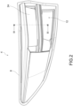
Figure 2 shows a perspective view, in an assembled configuration, of the lighting and/or signaling device inFigure 1 ; -
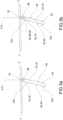
Figure 3a shows a sectional view of the lighting and/or signaling device inFigure 2 , along the section plane III-III, according to a solution of the known art; -
Figure 3b shows a sectional view of the lighting and/or signaling device inFigure 2 , along the section plane III-III, according to an embodiment of the present invention; -
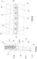
Figure 4 shows a perspective view of component IV shown inFigure 1 ; -
Figure 5 shows a top plan view of the component inFigure 4 ; -
Figure 6 shows a perspective view of an enlarged detail of the component inFigure 4 ; -
Figure 7 shows the enlarged detail VII indicated inFigure 4 ; -
Figure 8 shows the enlarged detail VIII indicated inFigure 5 . - The elements or parts of elements common to the embodiments described below will be indicated using the same numerals.
- With reference to the aforesaid drawings, a lighting and/or signaling device, such as an automotive light, to which the following disclosure refers without however losing in generality, is indicated as a whole by 4.
- As mentioned above, the expression "lighting and/or signaling device" may indifferently mean either an automotive rear light or an automotive front light, the latter also known as headlight or headlamp, comprising a light external to the vehicle having a lighting and/or signaling function, such as, for example, a position light, which may be a front position light, a taillight, a side marker, a turn signal, a brake light, a rear fog lamp, a high beam light, a dipped beam light, and the like.
- Thus, as better described below, the device in its signaling function may comprise the possibility of sending light signals, logos, but also words and lit messages of any kind. Thus, the device may perform a merely aesthetical function, such as lighting devices that show logos and the like, which may be arranged both outside and inside the vehicle.
- The lighting and/or
signaling device 4 comprises a container body orhollow housing 8, usually made of polymeric material, such as, for example acrylonitrile butadiene styrene, or ABS, which conventionally allows fixing the lighting and/orsignaling device 4 to the related vehicle or to any type of support. - For the purposes of the present invention, the container body or
housing 8 may have any shape, size or position: for example, thecontainer body 8 may also not be directly connected to the bodywork or other external fixings of the associable vehicle. - The
container body 8 delimits acontainment seat 12 which accommodates a plurality of components of said lighting and/or signaling device. - The
containment seat 12 in particular accommodates at least onelight source 16 arranged and supported inside saidcontainment seat 12. The at least onelight source 16 preferably comprises LED or mini LED light sources adapted to emit a light beam comprising a plurality of light rays 18 which extend along a main optical propagation axis X-X. - For example, a
lenticular body 20 may be placed at least partially to close thecontainer body 8 so as to close saidcontainment seat 12 which accommodates thelight source 16. - For the purposes of the present invention, the
lenticular body 20 is external to the lighting and/orsignaling device 4 so as to define at least one outer wall of the lighting and/or signaling device directly subject to the atmosphere, thus integrating with the line of the car, when thecontainer body 8 is firmly recessed in the enclosure of the vehicle. - According to possible embodiments, the material of the
lenticular body 20 is of polymeric type, that is a resin such as PMMA (poly methyl methacrylate), PC (polycarbonate) and the like. Said material of thelenticular body 20 is therefore at least partially transparent or semitransparent or translucent, one or more opaque portions being able to be included. - As shown, the
containment seat 12 that extends along afirst perimeter edge 28 is closed by thelenticular body 20 which extends along asecond perimeter edge 32 at least partially counter-shaped to and overlapping saidfirst perimeter edge 28. - The lighting and/or
signaling device 4 further comprises at least onelight guide 24 formed with a transparent polymeric material, such as PC, PMMA or the like, configured to at least partially receive the incoming light beam generated by saidlight source 16, transmit it by means of total internal reflection along a prevailing propagation direction and output it from thelenticular body 20, as better described below. - Said at least one
light guide 24 is configured to at least partially receive said light rays 18 at aninlet wall 36 thereof (called incoupling), convey the light rays 18 and extract said light rays 18 by means of a rear wall 40 thereof (called outcoupling). - In particular, said rear wall 40 is provided with a plurality of optical extractor elements 44 that extract the light rays 18 and transmit them externally to the
light guide 24 through afront wall 48 of thelight guide 24, opposite to said rear wall 40, along a transverse direction T-T, perpendicular to the main optical propagation axis X-X. - In particular, said optical extractor elements 44 of the rear wall 40 comprise local discontinuities or surface alterations or prisms or the like, capable of reflecting the light in specular or scattered manner; moreover, the rear wall 40 may be embossed or etched, comprising projected incisions capable of scattering light.
- Said
front wall 48 of thelight guide 24 in turn may comprise optical elements, such as cylindrical optics or pillow optics or the like, and/or scattering elements, such as an embossing portion and/or an etched portion. - According to the invention, with respect to a cross-section plane passing through said main optical propagation axis X-X and said transverse direction T-T, the
inlet wall 36 of thelight guide 24 has amiddle section 52 with polyline geometry comprising a plurality of rectilinear sections and/or curvilinear sections 56 so as to overall be convex on the side of the at least onelight source 16. The concept of polyline is to be understood in the broad sense: in other words, as better described below, the polyline is a set of rectilinear sections and/or curvilinear sections 56 that overall define a straight or (completely or partially) curved line that has a convexity on the side of thelight source 16. - Preferably, especially in the case of light guides having a length which is less than 50 mm, said polyline is configured so that the light rays 18, introduced through the
inlet wall 36 of thelight guide 24, hit the rear wall 40 directly or following a single reflection on thefront wall 48. Thereby, the scattering of the light rays on the rear wall 40 may be controlled so that it is uniform and homogeneous and does not have any light spots. For example, the comparison betweenFigures 3a and 3b shows how an inlet wall 36 (Figure 3a ) does not allow sufficiently spacing apart two contiguous light rays 18', 18'' from each other, while aninlet wall 36 overall having convex polyline allows increased spacing of said contiguous light rays 18', 18''. - According to a possible embodiment of the present invention, said polyline comprises two mutually angled consecutive rectilinear sections 56 which form an angle at the vertex which is greater than 180 degrees, on the side of the
LED light source 16. - According to a possible embodiment of the present invention, said polyline comprises at least one rectilinear section and one curvilinear section 56 that are consecutive to each other so as to obtain an overall convex polyline on the side of the at least one
light source 16. - According to a possible embodiment of the present invention, said polyline comprises two curvilinear sections 56 that are consecutive to each other so as to obtain an overall convex polyline on the side of the at least one
light source 16. - In general, the curvilinear sections 56 may be arcs of circle, ellipse, parabola, hyperbole and the like.
- According to the invention, the section plane passing through the main optical propagation axis X-X and the transverse direction T-T, the rectilinear and/or curvilinear sections 56 forming the polyline related to the cross section of the
inlet wall 36 of thelight guide 24 identify each one a skirt of theinlet wall 36. - According to the invention, the skirts of the
adjacent inlet wall 36 are inclined and joined to one another at a vertex line. - Preferably, each skirt of the
inlet wall 36 extends in a wavy manner along the longitudinal direction L-L. - In greater detail, and according to a possible embodiment of the present invention, each skirt of the
inlet wall 36 of thelight guide 24 comprises a plurality ofadjacent optics 84 along a longitudinal direction L-L, perpendicular to the transverse direction T-T and the main optical propagation direction X-X. Preferably, saidoptics 84 have a "V" or "U" profile with the vertex facing thelight source 16. - Therefore,
such optics 84 follow one another so as to give the skirt of the inlet wall 36 a wavy structure having a related phase, amplitude and frequency. - Preferably, skirts of the
inlet wall 36 have respective wavy structures having equal phase and/or amplitude and/or frequency. Obliviously, at least one among such phase and/or amplitude and/or frequency of a skirt may be different from the others. - According to a possible embodiment of the present invention, said
optics 84 are arranged along the longitudinal direction L-L according to a continuous sinusoidal pattern comprising alternatingridges 88 anddepressions 92, at aconstant pitch 96.Pitch 96 is the distance between twoconsecutive ridges 88 ordepressions 92 along said longitudinal direction L-L. - According to a possible embodiment of the present invention,
pitch 96 and the geometry of theoptics 84 are configured so that the light beam emitted by eachlight source 16 hits two or moreconsecutive ridges 88 ordepressions 92 ofoptics 84. - Preferably, said
optics 84 have a height, i.e., a distance between theridges 88 and thedepressions 92, that is the height of the sinusoid, which is less than 1 mm. - Again, with reference to
Figure 3b , a first skirt 56' of theinlet wall 36 is structured to refract and direct the light beam in a firstproximal zone 100 of the rear wall 40, while a second skirt 56'' of theinlet wall 36 is structured to refract and direct the light beam in a seconddistal zone 102 of the rear wall 40, so as to involve the whole rear wall 40, said firstproximal zone 100 and seconddistal zone 102 being contiguous to each other. In other words, since the first skirt 56' and the second skirt 56'' of theinlet wall 36 lie on respective mutually inclined lying planes, the light may be refracted with a much broader light distribution and thus involving the whole rear wall 40 - both the firstproximal zone 100 and the second distal zone 102 - without light concentrations in the firstproximal zone 100 of the rear wall 40. - According to a possible embodiment of the present invention, a
transverse thickness 60 of thelight guide 24 is equal to a subtendedcord 64 at transverse ends 66, 68 of said polyline. - Preferably, in order to optimize the optical efficiency of the system, a
light emission distribution 72 of saidlight sources 16 hastransverse amplitude 76 which is comparable, for example equal, to saidtransverse thickness 60 of thelight guide 24 so as to involve all the skirts. - According to a possible embodiment of the present invention, the
light guide 24, at theinlet wall 36, has a pair oftransverse appendices 80, on opposite sides with respect to saidmiddle section 52 with polyline geometry, so as to facilitate the position of thelight guide 24 in thecontainer body 8. - As can be appreciated from the above description, the present invention allows overcoming the drawbacks introduced in the known art.
- In particular, by virtue of the present invention, the outcoupling surface, or rear wall, of the light guide may be homogeneously lit by means of light rays emitted by the LED.
- After being refracted into the inlet wall, or incoupling, said light rays hit the rear wall directly or following a single rebound in the light guide: thereby, the mentioned homogeneity and the absence of undesired light spots may be obtained.
- It is therefore possible to provide long and thin light guides and/or light guide plates without the risk of having light spots on the outlet wall, thus creating homogeneous and uniform lighting.
- Those skilled in the art, with the object of meeting contingent and specific needs, can make several changes and variants to the lighting and/or signaling devices described without departing from the scope of protection of the present invention, the scope of protection being defined by the following claims.
Claims (17)
- A lighting and/or signaling device (4) for vehicles, comprising:- a container body (8) that delimits a containment seat (12) which extends along a first perimeter edge (28), closed by a lenticular body (20) which extends along a second perimeter edge (32) at least partially counter-shaped to and overlapping said first perimeter edge (28),- said containment seat (12) housing at least one LED or mini LED light source (16) adapted to emit a light beam comprising a plurality of light rays (18) which extend along a main optical propagation axis (X-X), and at least one light guide (24) configured to at least partially receive said light rays (18) at an inlet wall (36) thereof and to transmit and/or reflect said light rays (18) onto a rear wall (40) thereof,- said rear wall (40) being provided with a plurality of optical extractor elements (44) which extract the light rays (18) and transmit them externally to the light guide (24) through a front wall (48) of the light guide (24), opposite to said rear wall (40), along a transverse direction (T-T), perpendicular to the main optical propagation axis (X-X),- characterized in that with respect to a cross-section plane passing through said main optical propagation axis (X-X) and said transverse direction (T-T), said inlet wall (36) has a middle section (52) with polyline geometry comprising a plurality of rectilinear sections and/or curvilinear sections (56) so as to be overall convex on the side of the at least one light source (16),wherein the rectilinear and/or curvilinear sections (56) each identify a skirt of the inlet wall (36), wherein adjacent skirts of the inlet wall (36) are inclined and joined to one another at a vertex line.
- A lighting and/or signaling device (4) according to claim 1, wherein said polyline is configured so that the light rays (18), introduced through the inlet wall (36) of the light guide (24), hit the rear wall (40) directly or follow a single reflection on the front wall (48).
- A lighting and/or signaling device (4) according to claim 2, wherein the light guide (24) has a length which is shorter than 50 mm.
- A lighting and/or signaling device (4) according to claim 1, 2 or 3, wherein said polyline comprises two mutually angled consecutive rectilinear sections (56) which form an angle at the vertex that is greater than 180 degrees, on the side of the LED light source (16).
- A lighting and/or signaling device (4) according to claim 1, 2, 3 or 4, wherein said polyline comprises at least one rectilinear section (56) and one curvilinear section (56) which are consecutive to each other so as to obtain an overall convex polyline on the side of the at least one light source (16).
- A lighting and/or signaling device (4) according to any one of claims claim 1 to 5, wherein said polyline comprises at least two consecutive curvilinear sections (56) so as to obtain an overall convex polyline on the side of the at least one light source (16).
- A lighting and/or signaling device (4) according to any one of claims 1 to 6, wherein a transverse thickness (60) of the light guide (24) is equal to a subtended cord (64) at transverse ends (66, 68) of said polyline.
- A lighting and/or signaling device (4) according to claim 7, wherein a light emission portion (72) of said light sources (16) has a transverse amplitude (76) equal to said transverse thickness (60) of the light guide (24).
- A lighting and/or signaling device (4) according to any one of claims 1 to 8, wherein the light guide (24) has, at the inlet wall (36), a pair of transverse appendices (80), on opposite sides of said middle section (52) with polyline geometry.
- A lighting and/or signaling device (4) according to any one of claims 1 to 9, wherein each skirt of the inlet wall (36) comprises a plurality of adjacent optics (84) along a longitudinal direction (L-L), perpendicular to the transverse direction (T-T) and to the main optical propagation direction (X-X), said optics (84) having a "V" or "U" profile with the vertex facing the light source (16).
- A lighting and/or signaling device (4) according to claim 10, wherein each skirt of the inlet wall (36) extends in a wavy manner along the longitudinal direction (L-L).
- A lighting and/or signaling device (4) according to either of claims 10 or 11, wherein said optics (84) are arranged along the longitudinal direction (L-L) according to a continuous sinusoidal pattern comprising alternating ridges (88) and depressions (92), at a constant pitch (96).
- A lighting and/or signaling device (4) according to claim 12, wherein the pitch (96) and the geometry of the optics (84) are configured so that the light beam emitted by each light source hits two or more consecutive ridges (88) or depressions (92) of optics (84).
- A lighting and/or signaling device (4) according to claim 10, 11, 12 or 13, wherein said optics (84) have a height, i.e., a distance between the ridges (88) and the depressions (92), which is less than 1 mm.
- A lighting and/or signaling device (4) according to any one of claims 1 to 14, wherein a first skirt (56') of the inlet wall (36) is structured to refract and direct the light beam in a first proximal zone (100) of the rear wall (40), while a second skirt (56'') of the inlet wall (36) is structured to refract and direct the light beam in a second distal zone (102) of the rear wall (40), so as to involve the whole rear wall (40), said first proximal zone (100) and second distal zone (102) being contiguous to each other.
- A lighting and/or signaling device (4) according to any one of claims 1 to 15, wherein said optical extractor elements (44) of the rear wall (40) comprise optical elements, such as cylindrical optics or pillow optics or the like, and/or scattering elements, such as an embossing portion and/or an etched portion.
- A lighting and/or signaling device (4) according to any one of claims 1 to 16, wherein said front wall (48) of the light guide (24) comprises scattering elements and/or an embossed portion and/or an etched portion.
Priority Applications (1)
| Application Number | Priority Date | Filing Date | Title |
|---|---|---|---|
| EP22176412.9A EP4286742B1 (en) | 2022-05-31 | 2022-05-31 | Automotive lighting and/or signaling device with a light guide |
Applications Claiming Priority (1)
| Application Number | Priority Date | Filing Date | Title |
|---|---|---|---|
| EP22176412.9A EP4286742B1 (en) | 2022-05-31 | 2022-05-31 | Automotive lighting and/or signaling device with a light guide |
Publications (2)
| Publication Number | Publication Date |
|---|---|
| EP4286742A1 EP4286742A1 (en) | 2023-12-06 |
| EP4286742B1 true EP4286742B1 (en) | 2025-05-14 |
Family
ID=82656774
Family Applications (1)
| Application Number | Title | Priority Date | Filing Date |
|---|---|---|---|
| EP22176412.9A Active EP4286742B1 (en) | 2022-05-31 | 2022-05-31 | Automotive lighting and/or signaling device with a light guide |
Country Status (1)
| Country | Link |
|---|---|
| EP (1) | EP4286742B1 (en) |
Family Cites Families (13)
| Publication number | Priority date | Publication date | Assignee | Title |
|---|---|---|---|---|
| DE4129094B4 (en) * | 1991-09-02 | 2005-08-25 | Hella Kgaa Hueck & Co. | Signal light with LEDs as a light source for motor vehicles and their use for different signal light functions |
| DE19908961A1 (en) * | 1999-03-02 | 2000-09-07 | Valeo Beleuchtung Deutschland | Lights, in particular for motor vehicles |
| KR100506092B1 (en) * | 2003-04-16 | 2005-08-04 | 삼성전자주식회사 | Light guide panel of edge light type backlight apparatus and edge light type backlight apparatus using the same |
| US7808578B2 (en) * | 2007-07-12 | 2010-10-05 | Wintek Corporation | Light guide place and light-diffusing structure thereof |
| EP2354637B1 (en) * | 2010-01-30 | 2020-03-04 | HELLA GmbH & Co. KGaA | Illumination device for vehicles |
| TWI402467B (en) * | 2010-09-24 | 2013-07-21 | Wintek China Technology Ltd | Light guide pillar |
| FR3000569B1 (en) * | 2013-01-03 | 2015-02-13 | Peugeot Citroen Automobiles Sa | SCREEN LIGHTING DEVICE WITH LUMINOUS EDGE (S) |
| DE102013100557B4 (en) * | 2013-01-21 | 2022-07-07 | HELLA GmbH & Co. KGaA | Lighting device for vehicles |
| WO2014199563A1 (en) * | 2013-06-11 | 2014-12-18 | 株式会社小糸製作所 | Lamp for vehicles |
| CN104345377B (en) * | 2013-08-01 | 2017-07-21 | 扬升照明股份有限公司 | light guide plate and light source module |
| DE102015115969B4 (en) * | 2015-09-22 | 2026-02-05 | HELLA GmbH & Co. KGaA | Lighting device for vehicles |
| JP7292074B2 (en) * | 2019-03-22 | 2023-06-16 | スタンレー電気株式会社 | vehicle lamp |
| CN112443814B (en) * | 2019-08-28 | 2024-08-30 | 法雷奥照明湖北技术中心有限公司 | Light guide assembly, vehicle lamp and vehicle |
-
2022
- 2022-05-31 EP EP22176412.9A patent/EP4286742B1/en active Active
Also Published As
| Publication number | Publication date |
|---|---|
| EP4286742A1 (en) | 2023-12-06 |
Similar Documents
| Publication | Publication Date | Title |
|---|---|---|
| US7726854B2 (en) | Lighting or signal device with an optical guide for a motor vehicle | |
| US5707130A (en) | Taillight for vehicles, especially for motor vehicles | |
| EP1015811B1 (en) | Optics for separation of high and low intensity light | |
| US8317381B2 (en) | Vehicle light | |
| KR102590107B1 (en) | Automotive lighting and/or signalling device with segmented lighting portions | |
| EP3176500B1 (en) | Lighting device for vehicles | |
| EP3593037B1 (en) | Lighting device for vehicles | |
| JP6829973B2 (en) | Lamp unit | |
| EP3707028B1 (en) | Headlight for a vehicle | |
| EP3657069B1 (en) | Vehicle light | |
| JP5708991B2 (en) | Vehicle lamp and light guide lens used in vehicle lamp | |
| EP4286742A1 (en) | Automotive lighting and/or signaling device with a light guide | |
| JP2006012837A (en) | Illumination device or signal device having a light guide | |
| JP2016197576A (en) | Vehicular light guide body and vehicular lighting tool | |
| CN110500556B (en) | Light guide for a lamp, lamp for a motor vehicle and motor vehicle | |
| CN220355221U (en) | Light guide components, lighting or signaling devices and motor vehicles | |
| KR102721688B1 (en) | Lamp of vehicle | |
| US20040174714A1 (en) | Headlight for vehicles | |
| KR101074156B1 (en) | lamp structure of car | |
| JP7023780B2 (en) | Vehicle lighting | |
| CN117006440B (en) | Car light device | |
| KR102700639B1 (en) | Guide lamp for vehicle | |
| KR102746646B1 (en) | Guide lamp for vehicle | |
| CN218954705U (en) | Optical illumination assembly, lighting device and motor vehicle | |
| US20250052400A1 (en) | Lamp for vehicle |
Legal Events
| Date | Code | Title | Description |
|---|---|---|---|
| PUAI | Public reference made under article 153(3) epc to a published international application that has entered the european phase |
Free format text: ORIGINAL CODE: 0009012 |
|
| STAA | Information on the status of an ep patent application or granted ep patent |
Free format text: STATUS: THE APPLICATION HAS BEEN PUBLISHED |
|
| AK | Designated contracting states |
Kind code of ref document: A1 Designated state(s): AL AT BE BG CH CY CZ DE DK EE ES FI FR GB GR HR HU IE IS IT LI LT LU LV MC MK MT NL NO PL PT RO RS SE SI SK SM TR |
|
| P01 | Opt-out of the competence of the unified patent court (upc) registered |
Effective date: 20240116 |
|
| STAA | Information on the status of an ep patent application or granted ep patent |
Free format text: STATUS: REQUEST FOR EXAMINATION WAS MADE |
|
| 17P | Request for examination filed |
Effective date: 20240603 |
|
| RBV | Designated contracting states (corrected) |
Designated state(s): AL AT BE BG CH CY CZ DE DK EE ES FI FR GB GR HR HU IE IS IT LI LT LU LV MC MK MT NL NO PL PT RO RS SE SI SK SM TR |
|
| GRAP | Despatch of communication of intention to grant a patent |
Free format text: ORIGINAL CODE: EPIDOSNIGR1 |
|
| STAA | Information on the status of an ep patent application or granted ep patent |
Free format text: STATUS: GRANT OF PATENT IS INTENDED |
|
| INTG | Intention to grant announced |
Effective date: 20241213 |
|
| GRAS | Grant fee paid |
Free format text: ORIGINAL CODE: EPIDOSNIGR3 |
|
| GRAA | (expected) grant |
Free format text: ORIGINAL CODE: 0009210 |
|
| STAA | Information on the status of an ep patent application or granted ep patent |
Free format text: STATUS: THE PATENT HAS BEEN GRANTED |
|
| AK | Designated contracting states |
Kind code of ref document: B1 Designated state(s): AL AT BE BG CH CY CZ DE DK EE ES FI FR GB GR HR HU IE IS IT LI LT LU LV MC MK MT NL NO PL PT RO RS SE SI SK SM TR |
|
| REG | Reference to a national code |
Ref country code: GB Ref legal event code: FG4D |
|
| REG | Reference to a national code |
Ref country code: CH Ref legal event code: EP |
|
| REG | Reference to a national code |
Ref country code: IE Ref legal event code: FG4D |
|
| REG | Reference to a national code |
Ref country code: DE Ref legal event code: R096 Ref document number: 602022014531 Country of ref document: DE |
|
| REG | Reference to a national code |
Ref country code: NL Ref legal event code: MP Effective date: 20250514 |
|
| PG25 | Lapsed in a contracting state [announced via postgrant information from national office to epo] |
Ref country code: ES Free format text: LAPSE BECAUSE OF FAILURE TO SUBMIT A TRANSLATION OF THE DESCRIPTION OR TO PAY THE FEE WITHIN THE PRESCRIBED TIME-LIMIT Effective date: 20250514 Ref country code: FI Free format text: LAPSE BECAUSE OF FAILURE TO SUBMIT A TRANSLATION OF THE DESCRIPTION OR TO PAY THE FEE WITHIN THE PRESCRIBED TIME-LIMIT Effective date: 20250514 Ref country code: PT Free format text: LAPSE BECAUSE OF FAILURE TO SUBMIT A TRANSLATION OF THE DESCRIPTION OR TO PAY THE FEE WITHIN THE PRESCRIBED TIME-LIMIT Effective date: 20250915 |
|
| REG | Reference to a national code |
Ref country code: LT Ref legal event code: MG9D |
|
| PG25 | Lapsed in a contracting state [announced via postgrant information from national office to epo] |
Ref country code: GR Free format text: LAPSE BECAUSE OF FAILURE TO SUBMIT A TRANSLATION OF THE DESCRIPTION OR TO PAY THE FEE WITHIN THE PRESCRIBED TIME-LIMIT Effective date: 20250815 Ref country code: NO Free format text: LAPSE BECAUSE OF FAILURE TO SUBMIT A TRANSLATION OF THE DESCRIPTION OR TO PAY THE FEE WITHIN THE PRESCRIBED TIME-LIMIT Effective date: 20250814 |
|
| PG25 | Lapsed in a contracting state [announced via postgrant information from national office to epo] |
Ref country code: NL Free format text: LAPSE BECAUSE OF FAILURE TO SUBMIT A TRANSLATION OF THE DESCRIPTION OR TO PAY THE FEE WITHIN THE PRESCRIBED TIME-LIMIT Effective date: 20250514 Ref country code: PL Free format text: LAPSE BECAUSE OF FAILURE TO SUBMIT A TRANSLATION OF THE DESCRIPTION OR TO PAY THE FEE WITHIN THE PRESCRIBED TIME-LIMIT Effective date: 20250514 |
|
| PGFP | Annual fee paid to national office [announced via postgrant information from national office to epo] |
Ref country code: IT Payment date: 20250531 Year of fee payment: 4 |
|
| REG | Reference to a national code |
Ref country code: AT Ref legal event code: MK05 Ref document number: 1795035 Country of ref document: AT Kind code of ref document: T Effective date: 20250514 |
|
| PG25 | Lapsed in a contracting state [announced via postgrant information from national office to epo] |
Ref country code: BG Free format text: LAPSE BECAUSE OF FAILURE TO SUBMIT A TRANSLATION OF THE DESCRIPTION OR TO PAY THE FEE WITHIN THE PRESCRIBED TIME-LIMIT Effective date: 20250514 |
|
| PG25 | Lapsed in a contracting state [announced via postgrant information from national office to epo] |
Ref country code: HR Free format text: LAPSE BECAUSE OF FAILURE TO SUBMIT A TRANSLATION OF THE DESCRIPTION OR TO PAY THE FEE WITHIN THE PRESCRIBED TIME-LIMIT Effective date: 20250514 |
|
| PG25 | Lapsed in a contracting state [announced via postgrant information from national office to epo] |
Ref country code: AT Free format text: LAPSE BECAUSE OF FAILURE TO SUBMIT A TRANSLATION OF THE DESCRIPTION OR TO PAY THE FEE WITHIN THE PRESCRIBED TIME-LIMIT Effective date: 20250514 |
|
| PG25 | Lapsed in a contracting state [announced via postgrant information from national office to epo] |
Ref country code: RS Free format text: LAPSE BECAUSE OF FAILURE TO SUBMIT A TRANSLATION OF THE DESCRIPTION OR TO PAY THE FEE WITHIN THE PRESCRIBED TIME-LIMIT Effective date: 20250814 |
|
| PG25 | Lapsed in a contracting state [announced via postgrant information from national office to epo] |
Ref country code: IS Free format text: LAPSE BECAUSE OF FAILURE TO SUBMIT A TRANSLATION OF THE DESCRIPTION OR TO PAY THE FEE WITHIN THE PRESCRIBED TIME-LIMIT Effective date: 20250914 |
|
| PG25 | Lapsed in a contracting state [announced via postgrant information from national office to epo] |
Ref country code: LV Free format text: LAPSE BECAUSE OF FAILURE TO SUBMIT A TRANSLATION OF THE DESCRIPTION OR TO PAY THE FEE WITHIN THE PRESCRIBED TIME-LIMIT Effective date: 20250514 |
|
| REG | Reference to a national code |
Ref country code: DE Ref legal event code: R119 Ref document number: 602022014531 Country of ref document: DE |
|
| REG | Reference to a national code |
Ref country code: CH Ref legal event code: H13 Free format text: ST27 STATUS EVENT CODE: U-0-0-H10-H13 (AS PROVIDED BY THE NATIONAL OFFICE) Effective date: 20251223 |
|
| PG25 | Lapsed in a contracting state [announced via postgrant information from national office to epo] |
Ref country code: DK Free format text: LAPSE BECAUSE OF FAILURE TO SUBMIT A TRANSLATION OF THE DESCRIPTION OR TO PAY THE FEE WITHIN THE PRESCRIBED TIME-LIMIT Effective date: 20250514 Ref country code: SM Free format text: LAPSE BECAUSE OF FAILURE TO SUBMIT A TRANSLATION OF THE DESCRIPTION OR TO PAY THE FEE WITHIN THE PRESCRIBED TIME-LIMIT Effective date: 20250514 |
|
| PG25 | Lapsed in a contracting state [announced via postgrant information from national office to epo] |
Ref country code: LU Free format text: LAPSE BECAUSE OF NON-PAYMENT OF DUE FEES Effective date: 20250531 |
|
| PG25 | Lapsed in a contracting state [announced via postgrant information from national office to epo] |
Ref country code: CH Free format text: LAPSE BECAUSE OF NON-PAYMENT OF DUE FEES Effective date: 20250531 |
|
| PG25 | Lapsed in a contracting state [announced via postgrant information from national office to epo] |
Ref country code: CZ Free format text: LAPSE BECAUSE OF FAILURE TO SUBMIT A TRANSLATION OF THE DESCRIPTION OR TO PAY THE FEE WITHIN THE PRESCRIBED TIME-LIMIT Effective date: 20250514 |
|
| PG25 | Lapsed in a contracting state [announced via postgrant information from national office to epo] |
Ref country code: EE Free format text: LAPSE BECAUSE OF FAILURE TO SUBMIT A TRANSLATION OF THE DESCRIPTION OR TO PAY THE FEE WITHIN THE PRESCRIBED TIME-LIMIT Effective date: 20250514 |
|
| PG25 | Lapsed in a contracting state [announced via postgrant information from national office to epo] |
Ref country code: SK Free format text: LAPSE BECAUSE OF FAILURE TO SUBMIT A TRANSLATION OF THE DESCRIPTION OR TO PAY THE FEE WITHIN THE PRESCRIBED TIME-LIMIT Effective date: 20250514 |
|
| REG | Reference to a national code |
Ref country code: BE Ref legal event code: MM Effective date: 20250531 |
|
| PG25 | Lapsed in a contracting state [announced via postgrant information from national office to epo] |
Ref country code: MC Free format text: LAPSE BECAUSE OF FAILURE TO SUBMIT A TRANSLATION OF THE DESCRIPTION OR TO PAY THE FEE WITHIN THE PRESCRIBED TIME-LIMIT Effective date: 20250514 |
|
| PG25 | Lapsed in a contracting state [announced via postgrant information from national office to epo] |
Ref country code: RO Free format text: LAPSE BECAUSE OF FAILURE TO SUBMIT A TRANSLATION OF THE DESCRIPTION OR TO PAY THE FEE WITHIN THE PRESCRIBED TIME-LIMIT Effective date: 20250514 |
|
| PLBE | No opposition filed within time limit |
Free format text: ORIGINAL CODE: 0009261 |
|
| STAA | Information on the status of an ep patent application or granted ep patent |
Free format text: STATUS: NO OPPOSITION FILED WITHIN TIME LIMIT |
|
| REG | Reference to a national code |
Ref country code: CH Ref legal event code: L10 Free format text: ST27 STATUS EVENT CODE: U-0-0-L10-L00 (AS PROVIDED BY THE NATIONAL OFFICE) Effective date: 20260325 |
|
| PG25 | Lapsed in a contracting state [announced via postgrant information from national office to epo] |
Ref country code: IE Free format text: LAPSE BECAUSE OF NON-PAYMENT OF DUE FEES Effective date: 20250531 Ref country code: DE Free format text: LAPSE BECAUSE OF NON-PAYMENT OF DUE FEES Effective date: 20251202 |
|
| PG25 | Lapsed in a contracting state [announced via postgrant information from national office to epo] |
Ref country code: BE Free format text: LAPSE BECAUSE OF NON-PAYMENT OF DUE FEES Effective date: 20250531 |
|
| PG25 | Lapsed in a contracting state [announced via postgrant information from national office to epo] |
Ref country code: FR Free format text: LAPSE BECAUSE OF NON-PAYMENT OF DUE FEES Effective date: 20250714 |
|
| 26N | No opposition filed |
Effective date: 20260217 |