EP4286740A1 - Method and apparatus for manufacturing a hydrogen tank wall, and wall component for such tank wall - Google Patents
Method and apparatus for manufacturing a hydrogen tank wall, and wall component for such tank wall Download PDFInfo
- Publication number
- EP4286740A1 EP4286740A1 EP22177002.7A EP22177002A EP4286740A1 EP 4286740 A1 EP4286740 A1 EP 4286740A1 EP 22177002 A EP22177002 A EP 22177002A EP 4286740 A1 EP4286740 A1 EP 4286740A1
- Authority
- EP
- European Patent Office
- Prior art keywords
- wall component
- tank
- manufacturing
- cold spray
- hydrogen tank
- Prior art date
- Legal status (The legal status is an assumption and is not a legal conclusion. Google has not performed a legal analysis and makes no representation as to the accuracy of the status listed.)
- Withdrawn
Links
- 239000001257 hydrogen Substances 0.000 title claims abstract description 70
- 229910052739 hydrogen Inorganic materials 0.000 title claims abstract description 70
- UFHFLCQGNIYNRP-UHFFFAOYSA-N Hydrogen Chemical compound [H][H] UFHFLCQGNIYNRP-UHFFFAOYSA-N 0.000 title claims abstract description 64
- 238000004519 manufacturing process Methods 0.000 title claims abstract description 44
- 238000000034 method Methods 0.000 title claims abstract description 31
- 239000007921 spray Substances 0.000 claims abstract description 40
- 238000000576 coating method Methods 0.000 claims abstract description 30
- 239000007769 metal material Substances 0.000 claims abstract description 30
- 239000011248 coating agent Substances 0.000 claims abstract description 28
- 239000000835 fiber Substances 0.000 claims abstract description 22
- 239000011208 reinforced composite material Substances 0.000 claims abstract description 18
- 239000002131 composite material Substances 0.000 claims description 22
- 238000010288 cold spraying Methods 0.000 claims description 18
- 238000005507 spraying Methods 0.000 claims description 17
- 239000000758 substrate Substances 0.000 claims description 14
- 239000007789 gas Substances 0.000 claims description 13
- 239000000843 powder Substances 0.000 claims description 13
- 239000002245 particle Substances 0.000 claims description 9
- IJGRMHOSHXDMSA-UHFFFAOYSA-N Atomic nitrogen Chemical compound N#N IJGRMHOSHXDMSA-UHFFFAOYSA-N 0.000 claims description 4
- 229910001374 Invar Inorganic materials 0.000 claims description 4
- 238000004804 winding Methods 0.000 claims description 4
- RTAQQCXQSZGOHL-UHFFFAOYSA-N Titanium Chemical compound [Ti] RTAQQCXQSZGOHL-UHFFFAOYSA-N 0.000 claims description 3
- 239000012159 carrier gas Substances 0.000 claims description 3
- 239000011261 inert gas Substances 0.000 claims description 3
- 229910052756 noble gas Inorganic materials 0.000 claims description 3
- WFKWXMTUELFFGS-UHFFFAOYSA-N tungsten Chemical compound [W] WFKWXMTUELFFGS-UHFFFAOYSA-N 0.000 claims description 3
- 229910000640 Fe alloy Inorganic materials 0.000 claims description 2
- 229910000990 Ni alloy Inorganic materials 0.000 claims description 2
- 229910045601 alloy Inorganic materials 0.000 claims description 2
- 239000000956 alloy Substances 0.000 claims description 2
- 239000001307 helium Substances 0.000 claims description 2
- 229910052734 helium Inorganic materials 0.000 claims description 2
- SWQJXJOGLNCZEY-UHFFFAOYSA-N helium atom Chemical compound [He] SWQJXJOGLNCZEY-UHFFFAOYSA-N 0.000 claims description 2
- 229910052757 nitrogen Inorganic materials 0.000 claims description 2
- 239000004918 carbon fiber reinforced polymer Substances 0.000 claims 1
- 239000007788 liquid Substances 0.000 description 11
- 239000000446 fuel Substances 0.000 description 7
- 150000002431 hydrogen Chemical class 0.000 description 7
- 239000000463 material Substances 0.000 description 6
- 238000003860 storage Methods 0.000 description 6
- 229910052751 metal Inorganic materials 0.000 description 5
- 239000002184 metal Substances 0.000 description 5
- 239000004033 plastic Substances 0.000 description 4
- 229920003023 plastic Polymers 0.000 description 4
- OKTJSMMVPCPJKN-UHFFFAOYSA-N Carbon Chemical compound [C] OKTJSMMVPCPJKN-UHFFFAOYSA-N 0.000 description 3
- 229910052799 carbon Inorganic materials 0.000 description 3
- 229910001092 metal group alloy Inorganic materials 0.000 description 3
- 150000002739 metals Chemical class 0.000 description 3
- 239000007787 solid Substances 0.000 description 3
- 238000010586 diagram Methods 0.000 description 2
- 238000004146 energy storage Methods 0.000 description 2
- 239000012530 fluid Substances 0.000 description 2
- 239000011159 matrix material Substances 0.000 description 2
- 229910002555 FeNi Inorganic materials 0.000 description 1
- 229920002430 Fibre-reinforced plastic Polymers 0.000 description 1
- QVGXLLKOCUKJST-UHFFFAOYSA-N atomic oxygen Chemical compound [O] QVGXLLKOCUKJST-UHFFFAOYSA-N 0.000 description 1
- POIUWJQBRNEFGX-XAMSXPGMSA-N cathelicidin Chemical compound C([C@@H](C(=O)N[C@@H](CCCNC(N)=N)C(=O)N[C@@H](CCCCN)C(=O)N[C@@H](CO)C(=O)N[C@@H](CCCCN)C(=O)N[C@@H](CCC(O)=O)C(=O)N[C@@H](CCCCN)C(=O)N[C@@H]([C@@H](C)CC)C(=O)NCC(=O)N[C@@H](CCCCN)C(=O)N[C@@H](CCC(O)=O)C(=O)N[C@@H](CC=1C=CC=CC=1)C(=O)N[C@@H](CCCCN)C(=O)N[C@@H](CCCNC(N)=N)C(=O)N[C@@H]([C@@H](C)CC)C(=O)N[C@@H](C(C)C)C(=O)N[C@@H](CCC(N)=O)C(=O)N[C@@H](CCCNC(N)=N)C(=O)N[C@@H]([C@@H](C)CC)C(=O)N[C@@H](CCCCN)C(=O)N[C@@H](CC(O)=O)C(=O)N[C@@H](CC=1C=CC=CC=1)C(=O)N[C@@H](CC(C)C)C(=O)N[C@@H](CCCNC(N)=N)C(=O)N[C@@H](CC(N)=O)C(=O)N[C@@H](CC(C)C)C(=O)N[C@@H](C(C)C)C(=O)N1[C@@H](CCC1)C(=O)N[C@@H](CCCNC(N)=N)C(=O)N[C@@H]([C@@H](C)O)C(=O)N[C@@H](CCC(O)=O)C(=O)N[C@@H](CO)C(O)=O)NC(=O)[C@H](CC=1C=CC=CC=1)NC(=O)[C@H](CC(O)=O)NC(=O)CNC(=O)[C@H](CC(C)C)NC(=O)[C@@H](N)CC(C)C)C1=CC=CC=C1 POIUWJQBRNEFGX-XAMSXPGMSA-N 0.000 description 1
- 239000000919 ceramic Substances 0.000 description 1
- 230000006835 compression Effects 0.000 description 1
- 238000007906 compression Methods 0.000 description 1
- 230000001419 dependent effect Effects 0.000 description 1
- 238000000151 deposition Methods 0.000 description 1
- 238000005137 deposition process Methods 0.000 description 1
- 238000005516 engineering process Methods 0.000 description 1
- 239000011151 fibre-reinforced plastic Substances 0.000 description 1
- 238000010285 flame spraying Methods 0.000 description 1
- 238000002955 isolation Methods 0.000 description 1
- 239000003350 kerosene Substances 0.000 description 1
- 239000001301 oxygen Substances 0.000 description 1
- 229910052760 oxygen Inorganic materials 0.000 description 1
- 238000007750 plasma spraying Methods 0.000 description 1
- 229920000642 polymer Polymers 0.000 description 1
- 238000007751 thermal spraying Methods 0.000 description 1
Images


Classifications
-
- F—MECHANICAL ENGINEERING; LIGHTING; HEATING; WEAPONS; BLASTING
- F17—STORING OR DISTRIBUTING GASES OR LIQUIDS
- F17C—VESSELS FOR CONTAINING OR STORING COMPRESSED, LIQUEFIED OR SOLIDIFIED GASES; FIXED-CAPACITY GAS-HOLDERS; FILLING VESSELS WITH, OR DISCHARGING FROM VESSELS, COMPRESSED, LIQUEFIED, OR SOLIDIFIED GASES
- F17C13/00—Details of vessels or of the filling or discharging of vessels
- F17C13/005—Details of vessels or of the filling or discharging of vessels for medium-size and small storage vessels not under pressure
-
- F—MECHANICAL ENGINEERING; LIGHTING; HEATING; WEAPONS; BLASTING
- F17—STORING OR DISTRIBUTING GASES OR LIQUIDS
- F17C—VESSELS FOR CONTAINING OR STORING COMPRESSED, LIQUEFIED OR SOLIDIFIED GASES; FIXED-CAPACITY GAS-HOLDERS; FILLING VESSELS WITH, OR DISCHARGING FROM VESSELS, COMPRESSED, LIQUEFIED, OR SOLIDIFIED GASES
- F17C2201/00—Vessel construction, in particular geometry, arrangement or size
- F17C2201/01—Shape
- F17C2201/0104—Shape cylindrical
- F17C2201/0109—Shape cylindrical with exteriorly curved end-piece
-
- F—MECHANICAL ENGINEERING; LIGHTING; HEATING; WEAPONS; BLASTING
- F17—STORING OR DISTRIBUTING GASES OR LIQUIDS
- F17C—VESSELS FOR CONTAINING OR STORING COMPRESSED, LIQUEFIED OR SOLIDIFIED GASES; FIXED-CAPACITY GAS-HOLDERS; FILLING VESSELS WITH, OR DISCHARGING FROM VESSELS, COMPRESSED, LIQUEFIED, OR SOLIDIFIED GASES
- F17C2201/00—Vessel construction, in particular geometry, arrangement or size
- F17C2201/03—Orientation
- F17C2201/035—Orientation with substantially horizontal main axis
-
- F—MECHANICAL ENGINEERING; LIGHTING; HEATING; WEAPONS; BLASTING
- F17—STORING OR DISTRIBUTING GASES OR LIQUIDS
- F17C—VESSELS FOR CONTAINING OR STORING COMPRESSED, LIQUEFIED OR SOLIDIFIED GASES; FIXED-CAPACITY GAS-HOLDERS; FILLING VESSELS WITH, OR DISCHARGING FROM VESSELS, COMPRESSED, LIQUEFIED, OR SOLIDIFIED GASES
- F17C2201/00—Vessel construction, in particular geometry, arrangement or size
- F17C2201/05—Size
- F17C2201/054—Size medium (>1 m3)
-
- F—MECHANICAL ENGINEERING; LIGHTING; HEATING; WEAPONS; BLASTING
- F17—STORING OR DISTRIBUTING GASES OR LIQUIDS
- F17C—VESSELS FOR CONTAINING OR STORING COMPRESSED, LIQUEFIED OR SOLIDIFIED GASES; FIXED-CAPACITY GAS-HOLDERS; FILLING VESSELS WITH, OR DISCHARGING FROM VESSELS, COMPRESSED, LIQUEFIED, OR SOLIDIFIED GASES
- F17C2203/00—Vessel construction, in particular walls or details thereof
- F17C2203/06—Materials for walls or layers thereof; Properties or structures of walls or their materials
- F17C2203/0602—Wall structures; Special features thereof
- F17C2203/0607—Coatings
-
- F—MECHANICAL ENGINEERING; LIGHTING; HEATING; WEAPONS; BLASTING
- F17—STORING OR DISTRIBUTING GASES OR LIQUIDS
- F17C—VESSELS FOR CONTAINING OR STORING COMPRESSED, LIQUEFIED OR SOLIDIFIED GASES; FIXED-CAPACITY GAS-HOLDERS; FILLING VESSELS WITH, OR DISCHARGING FROM VESSELS, COMPRESSED, LIQUEFIED, OR SOLIDIFIED GASES
- F17C2203/00—Vessel construction, in particular walls or details thereof
- F17C2203/06—Materials for walls or layers thereof; Properties or structures of walls or their materials
- F17C2203/0634—Materials for walls or layers thereof
- F17C2203/0636—Metals
- F17C2203/0648—Alloys or compositions of metals
-
- F—MECHANICAL ENGINEERING; LIGHTING; HEATING; WEAPONS; BLASTING
- F17—STORING OR DISTRIBUTING GASES OR LIQUIDS
- F17C—VESSELS FOR CONTAINING OR STORING COMPRESSED, LIQUEFIED OR SOLIDIFIED GASES; FIXED-CAPACITY GAS-HOLDERS; FILLING VESSELS WITH, OR DISCHARGING FROM VESSELS, COMPRESSED, LIQUEFIED, OR SOLIDIFIED GASES
- F17C2203/00—Vessel construction, in particular walls or details thereof
- F17C2203/06—Materials for walls or layers thereof; Properties or structures of walls or their materials
- F17C2203/0634—Materials for walls or layers thereof
- F17C2203/0636—Metals
- F17C2203/0648—Alloys or compositions of metals
- F17C2203/0651—Invar
-
- F—MECHANICAL ENGINEERING; LIGHTING; HEATING; WEAPONS; BLASTING
- F17—STORING OR DISTRIBUTING GASES OR LIQUIDS
- F17C—VESSELS FOR CONTAINING OR STORING COMPRESSED, LIQUEFIED OR SOLIDIFIED GASES; FIXED-CAPACITY GAS-HOLDERS; FILLING VESSELS WITH, OR DISCHARGING FROM VESSELS, COMPRESSED, LIQUEFIED, OR SOLIDIFIED GASES
- F17C2203/00—Vessel construction, in particular walls or details thereof
- F17C2203/06—Materials for walls or layers thereof; Properties or structures of walls or their materials
- F17C2203/0634—Materials for walls or layers thereof
- F17C2203/0658—Synthetics
- F17C2203/0663—Synthetics in form of fibers or filaments
-
- F—MECHANICAL ENGINEERING; LIGHTING; HEATING; WEAPONS; BLASTING
- F17—STORING OR DISTRIBUTING GASES OR LIQUIDS
- F17C—VESSELS FOR CONTAINING OR STORING COMPRESSED, LIQUEFIED OR SOLIDIFIED GASES; FIXED-CAPACITY GAS-HOLDERS; FILLING VESSELS WITH, OR DISCHARGING FROM VESSELS, COMPRESSED, LIQUEFIED, OR SOLIDIFIED GASES
- F17C2203/00—Vessel construction, in particular walls or details thereof
- F17C2203/06—Materials for walls or layers thereof; Properties or structures of walls or their materials
- F17C2203/0634—Materials for walls or layers thereof
- F17C2203/0658—Synthetics
- F17C2203/0675—Synthetics with details of composition
-
- F—MECHANICAL ENGINEERING; LIGHTING; HEATING; WEAPONS; BLASTING
- F17—STORING OR DISTRIBUTING GASES OR LIQUIDS
- F17C—VESSELS FOR CONTAINING OR STORING COMPRESSED, LIQUEFIED OR SOLIDIFIED GASES; FIXED-CAPACITY GAS-HOLDERS; FILLING VESSELS WITH, OR DISCHARGING FROM VESSELS, COMPRESSED, LIQUEFIED, OR SOLIDIFIED GASES
- F17C2209/00—Vessel construction, in particular methods of manufacturing
- F17C2209/21—Shaping processes
- F17C2209/2154—Winding
- F17C2209/2163—Winding with a mandrel
-
- F—MECHANICAL ENGINEERING; LIGHTING; HEATING; WEAPONS; BLASTING
- F17—STORING OR DISTRIBUTING GASES OR LIQUIDS
- F17C—VESSELS FOR CONTAINING OR STORING COMPRESSED, LIQUEFIED OR SOLIDIFIED GASES; FIXED-CAPACITY GAS-HOLDERS; FILLING VESSELS WITH, OR DISCHARGING FROM VESSELS, COMPRESSED, LIQUEFIED, OR SOLIDIFIED GASES
- F17C2209/00—Vessel construction, in particular methods of manufacturing
- F17C2209/22—Assembling processes
- F17C2209/225—Spraying
-
- F—MECHANICAL ENGINEERING; LIGHTING; HEATING; WEAPONS; BLASTING
- F17—STORING OR DISTRIBUTING GASES OR LIQUIDS
- F17C—VESSELS FOR CONTAINING OR STORING COMPRESSED, LIQUEFIED OR SOLIDIFIED GASES; FIXED-CAPACITY GAS-HOLDERS; FILLING VESSELS WITH, OR DISCHARGING FROM VESSELS, COMPRESSED, LIQUEFIED, OR SOLIDIFIED GASES
- F17C2209/00—Vessel construction, in particular methods of manufacturing
- F17C2209/23—Manufacturing of particular parts or at special locations
- F17C2209/232—Manufacturing of particular parts or at special locations of walls
-
- F—MECHANICAL ENGINEERING; LIGHTING; HEATING; WEAPONS; BLASTING
- F17—STORING OR DISTRIBUTING GASES OR LIQUIDS
- F17C—VESSELS FOR CONTAINING OR STORING COMPRESSED, LIQUEFIED OR SOLIDIFIED GASES; FIXED-CAPACITY GAS-HOLDERS; FILLING VESSELS WITH, OR DISCHARGING FROM VESSELS, COMPRESSED, LIQUEFIED, OR SOLIDIFIED GASES
- F17C2221/00—Handled fluid, in particular type of fluid
- F17C2221/01—Pure fluids
- F17C2221/012—Hydrogen
-
- F—MECHANICAL ENGINEERING; LIGHTING; HEATING; WEAPONS; BLASTING
- F17—STORING OR DISTRIBUTING GASES OR LIQUIDS
- F17C—VESSELS FOR CONTAINING OR STORING COMPRESSED, LIQUEFIED OR SOLIDIFIED GASES; FIXED-CAPACITY GAS-HOLDERS; FILLING VESSELS WITH, OR DISCHARGING FROM VESSELS, COMPRESSED, LIQUEFIED, OR SOLIDIFIED GASES
- F17C2223/00—Handled fluid before transfer, i.e. state of fluid when stored in the vessel or before transfer from the vessel
- F17C2223/01—Handled fluid before transfer, i.e. state of fluid when stored in the vessel or before transfer from the vessel characterised by the phase
- F17C2223/0146—Two-phase
- F17C2223/0153—Liquefied gas, e.g. LPG, GPL
- F17C2223/0161—Liquefied gas, e.g. LPG, GPL cryogenic, e.g. LNG, GNL, PLNG
-
- F—MECHANICAL ENGINEERING; LIGHTING; HEATING; WEAPONS; BLASTING
- F17—STORING OR DISTRIBUTING GASES OR LIQUIDS
- F17C—VESSELS FOR CONTAINING OR STORING COMPRESSED, LIQUEFIED OR SOLIDIFIED GASES; FIXED-CAPACITY GAS-HOLDERS; FILLING VESSELS WITH, OR DISCHARGING FROM VESSELS, COMPRESSED, LIQUEFIED, OR SOLIDIFIED GASES
- F17C2223/00—Handled fluid before transfer, i.e. state of fluid when stored in the vessel or before transfer from the vessel
- F17C2223/03—Handled fluid before transfer, i.e. state of fluid when stored in the vessel or before transfer from the vessel characterised by the pressure level
- F17C2223/033—Small pressure, e.g. for liquefied gas
-
- F—MECHANICAL ENGINEERING; LIGHTING; HEATING; WEAPONS; BLASTING
- F17—STORING OR DISTRIBUTING GASES OR LIQUIDS
- F17C—VESSELS FOR CONTAINING OR STORING COMPRESSED, LIQUEFIED OR SOLIDIFIED GASES; FIXED-CAPACITY GAS-HOLDERS; FILLING VESSELS WITH, OR DISCHARGING FROM VESSELS, COMPRESSED, LIQUEFIED, OR SOLIDIFIED GASES
- F17C2260/00—Purposes of gas storage and gas handling
- F17C2260/01—Improving mechanical properties or manufacturing
- F17C2260/012—Reducing weight
-
- F—MECHANICAL ENGINEERING; LIGHTING; HEATING; WEAPONS; BLASTING
- F17—STORING OR DISTRIBUTING GASES OR LIQUIDS
- F17C—VESSELS FOR CONTAINING OR STORING COMPRESSED, LIQUEFIED OR SOLIDIFIED GASES; FIXED-CAPACITY GAS-HOLDERS; FILLING VESSELS WITH, OR DISCHARGING FROM VESSELS, COMPRESSED, LIQUEFIED, OR SOLIDIFIED GASES
- F17C2260/00—Purposes of gas storage and gas handling
- F17C2260/03—Dealing with losses
- F17C2260/035—Dealing with losses of fluid
- F17C2260/036—Avoiding leaks
-
- F—MECHANICAL ENGINEERING; LIGHTING; HEATING; WEAPONS; BLASTING
- F17—STORING OR DISTRIBUTING GASES OR LIQUIDS
- F17C—VESSELS FOR CONTAINING OR STORING COMPRESSED, LIQUEFIED OR SOLIDIFIED GASES; FIXED-CAPACITY GAS-HOLDERS; FILLING VESSELS WITH, OR DISCHARGING FROM VESSELS, COMPRESSED, LIQUEFIED, OR SOLIDIFIED GASES
- F17C2270/00—Applications
- F17C2270/01—Applications for fluid transport or storage
- F17C2270/0165—Applications for fluid transport or storage on the road
- F17C2270/0168—Applications for fluid transport or storage on the road by vehicles
-
- F—MECHANICAL ENGINEERING; LIGHTING; HEATING; WEAPONS; BLASTING
- F17—STORING OR DISTRIBUTING GASES OR LIQUIDS
- F17C—VESSELS FOR CONTAINING OR STORING COMPRESSED, LIQUEFIED OR SOLIDIFIED GASES; FIXED-CAPACITY GAS-HOLDERS; FILLING VESSELS WITH, OR DISCHARGING FROM VESSELS, COMPRESSED, LIQUEFIED, OR SOLIDIFIED GASES
- F17C2270/00—Applications
- F17C2270/01—Applications for fluid transport or storage
- F17C2270/0165—Applications for fluid transport or storage on the road
- F17C2270/0168—Applications for fluid transport or storage on the road by vehicles
- F17C2270/0171—Trucks
-
- F—MECHANICAL ENGINEERING; LIGHTING; HEATING; WEAPONS; BLASTING
- F17—STORING OR DISTRIBUTING GASES OR LIQUIDS
- F17C—VESSELS FOR CONTAINING OR STORING COMPRESSED, LIQUEFIED OR SOLIDIFIED GASES; FIXED-CAPACITY GAS-HOLDERS; FILLING VESSELS WITH, OR DISCHARGING FROM VESSELS, COMPRESSED, LIQUEFIED, OR SOLIDIFIED GASES
- F17C2270/00—Applications
- F17C2270/01—Applications for fluid transport or storage
- F17C2270/0165—Applications for fluid transport or storage on the road
- F17C2270/0168—Applications for fluid transport or storage on the road by vehicles
- F17C2270/0173—Railways
-
- F—MECHANICAL ENGINEERING; LIGHTING; HEATING; WEAPONS; BLASTING
- F17—STORING OR DISTRIBUTING GASES OR LIQUIDS
- F17C—VESSELS FOR CONTAINING OR STORING COMPRESSED, LIQUEFIED OR SOLIDIFIED GASES; FIXED-CAPACITY GAS-HOLDERS; FILLING VESSELS WITH, OR DISCHARGING FROM VESSELS, COMPRESSED, LIQUEFIED, OR SOLIDIFIED GASES
- F17C2270/00—Applications
- F17C2270/01—Applications for fluid transport or storage
- F17C2270/0165—Applications for fluid transport or storage on the road
- F17C2270/0168—Applications for fluid transport or storage on the road by vehicles
- F17C2270/0178—Cars
-
- F—MECHANICAL ENGINEERING; LIGHTING; HEATING; WEAPONS; BLASTING
- F17—STORING OR DISTRIBUTING GASES OR LIQUIDS
- F17C—VESSELS FOR CONTAINING OR STORING COMPRESSED, LIQUEFIED OR SOLIDIFIED GASES; FIXED-CAPACITY GAS-HOLDERS; FILLING VESSELS WITH, OR DISCHARGING FROM VESSELS, COMPRESSED, LIQUEFIED, OR SOLIDIFIED GASES
- F17C2270/00—Applications
- F17C2270/01—Applications for fluid transport or storage
- F17C2270/0165—Applications for fluid transport or storage on the road
- F17C2270/0184—Fuel cells
-
- F—MECHANICAL ENGINEERING; LIGHTING; HEATING; WEAPONS; BLASTING
- F17—STORING OR DISTRIBUTING GASES OR LIQUIDS
- F17C—VESSELS FOR CONTAINING OR STORING COMPRESSED, LIQUEFIED OR SOLIDIFIED GASES; FIXED-CAPACITY GAS-HOLDERS; FILLING VESSELS WITH, OR DISCHARGING FROM VESSELS, COMPRESSED, LIQUEFIED, OR SOLIDIFIED GASES
- F17C2270/00—Applications
- F17C2270/01—Applications for fluid transport or storage
- F17C2270/0186—Applications for fluid transport or storage in the air or in space
- F17C2270/0189—Planes
Definitions
- the invention relates to a manufacturing method for manufacturing a hydrogen tank wall, especially a cryogenic tank wall. Further, the invention relates to a hydrogen tank, especially a cryogenic tank, for a vehicle, especially an aircraft, comprising a tank wall component having a substrate of fibre reinforced composite material. Still further, the invention relates to a manufacturing apparatus for manufacturing a hydrogen tank, especially a cryogenic tank.
- Cryogenic storage tanks may be used for storing liquid hydrogen, for example, for use as a fuel for driving a vehicle.
- the vehicle may be a motor vehicle such as a car, lorry or train or may be an aircraft.
- Citations [1] and [2] disclose a tank for the cryogenic storage of hydrogen and an aircraft with a tank installed therein. Liquid hydrogen stored within the tank is used as a fuel for the aircraft engine in place of carbon-based fuels such as kerosene.
- the cryogenic storage tank is typically substantially cylindrical and includes openings for allowing the tank to be filled with hydrogen as well as to supply the stored liquid hydrogen to the engine.
- Lightweight energy storage is a key topic for next generation aircrafts. Storage systems with high energy density are one of the key challenges for future electrical propulsion-based systems. Different energy storage systems are available today, whereas pressurized ( ⁇ 700 bar) or cryogenic Hydrogen (14 K ⁇ T ⁇ 21 K) paired with fuel cells or direct burn are interesting solutions for next flight vehicles. Hydrogen (H2) is the molecule with lowest density and smallest diameter in nature, which is why the storage in tanks is very complex and hardly achievable without leakage over longer durations.
- Hydrogen offers high energy densities, whereas the storage technique (cryogenic, compressed, solid state/absorbed) is a key issue. Hydrogen can be compressed and/or cooled down to cryogenic temperatures to increase the volumetric and gravimetric energy density. Usually, complex tank systems are needed with individual requirements to the materials, design and working principle e.g., regarding operational safety.
- Compressed and cryogenic hydrogen are the techniques of choice for today's vehicles, like cars or airplanes.
- Cryogenic tanks can achieve the lowest added weight wherein, with the present known technologies, about 0.2 kg - 0.5 kg tank weight is needed per kg stored H2.
- Conventional tanks work with applied inner pressure to avoid gas ingress from outside.
- tank material typically metals, metal alloys and composites are in use.
- Full composite tanks can be challenging because of the long in-service life of civil aircraft. Hydrogen leakage may also be an issue.
- An object of the invention is to improve leak tightness of hydrogen tanks made of composite material.
- Preferred embodiments are subject-matters of the dependent claims.
- the invention provides a manufacturing method for manufacturing a hydrogen tank wall, especially a cryogenic tank wall for a tank for storing liquid hydrogen, comprising the steps of:
- step b) comprises: cold spraying a metal material having a thermal expansion coefficient that is lower than a thermal expansion component of the reinforced composite material onto at least one surface of the wall component.
- the cold spray coating applied to at least one surface of the wall component substrate has a lower CTE as the substrate which is made from composite material.
- step a) comprises a1) providing at least one wall component in a tube shape.
- step a) comprises a2) providing at least one wall component with the shape of a cap.
- step a) comprises a3) winding a prepreg on a winder in order to form the at least one wall component.
- step a) comprises a4) stacking several prepregs with different fibre orientation in order to form the at least one wall component.
- step a) comprises a5) combining layers of composite material with different fibre orientations to form the at least one wall component.
- step a) comprises a6) providing the at least one wall component having a linear thermal expansion coefficient CTEc with 2*10 -6 K -1 ⁇ CTEc ⁇ 34*10 -6 K -1 , preferably 5*10 -6 K -1 ⁇ CTEc ⁇ 15*10 -6 K -1 , most preferred 9*10 -6 K -1 ⁇ CTEc ⁇ 10*10 -6 K -1 .
- step a) comprises a7) providing the at least one wall component made from a CFRP composite material.
- step b) comprises: b1) conducting the cold spray process with a powder from metallic material having a linear thermal expansion coefficient CTE M with -30*10 -6 K -1 ⁇ CTE M ⁇ 9*10 -6 K -1 .
- step b) comprises: b2) using one or several metallic materials from the group consisting of iron alloy, nickel alloy, FeNi36(Invar), FeNi36(extrapure), Fe-29Ni-17CO, wolfram, titan, and negative CTE alloy.
- step b) comprises: b3) using a carrier gas from the group consisting of air, inert gas, noble gas, nitrogen, and helium.
- a carrier gas from the group consisting of air, inert gas, noble gas, nitrogen, and helium.
- step b) comprises: b4) conducting the cold spray process with a gas pressure p with 40 bar ⁇ p ⁇ 70 bar.
- step b) comprises: b5) conducting the cold spray process with a gas temperature T with 750°C ⁇ T ⁇ 1000°C.
- step b) comprises: b6) conducting the cold spray process with a powder having particle diameters pd with 25 ⁇ m ⁇ pd ⁇ 60 ⁇ m.
- step b) comprises: b7) applying a bonding layer on the composite material surface to be coated and applying the coating by the cold spray process over the bonding layer.
- step b) comprises: b8) coating an inner surface of the wall component which forms, in use of the wall component in the cryogenic tank, an inner surface area of the tank.
- step b) comprises: b9) conducting the cold spray process with a spray head arranged on a robotic arm.
- the invention provides a hydrogen tank for a vehicle, especially an aircraft, preferably a cryogen tank for storing liquified hydrogen, the hydrogen tank comprising a tank wall component having a substrate of fibre reinforced composite material coated with a cold sprayed metallic material layer.
- the metallic material layer has a lower thermal expansion coefficient as the fibre-reinforced composite material layer.
- the fibre-reinforced composite material substrate has a linear thermal expansion coefficient CTEc with 2*10 -6 K -1 ⁇ CTE C ⁇ 34*10 -6 K -1 , more preferably 5*10 -6 K -1 ⁇ CTEc ⁇ 15*10 -6 K -1 , most preferred 9*10 -6 K -1 ⁇ CTEc ⁇ 10*10 -6 K -1 and/or wherein the metallic material of the coating has a linear thermal expansion coefficient CTE M with -30*10 -6 K -1 ⁇ CTE M ⁇ 9*10 -6 K -1
- the wall component has an inner surface defining a portion of the inner tank surface coated with the cold sprayed metallic material.
- the hydrogen tank is achieved by the manufacturing method according to any of the aforementioned embodiments.
- the invention provides a vehicle, especially an aircraft, comprising a hydrogen tank according to any of the aforementioned embodiments.
- the invention provides a manufacturing apparatus for manufacturing a hydrogen tank, especially a cryogen tank for storing liquid hydrogen (LH2) comprising
- Preferred embodiments of the invention relate to a cold spray inner coating for H2-tanks.
- the proposed coating relates to an application for a tank containing cryogenic fluids (H2). Therefore, an application within hydrogen powered aircrafts is possible.
- Tank structures for cryogenic fluids like liquid H2 are often manufactured from metallic material. For an aeronautical application these tanks are too heavy. The use of composite material for cryogenic tanks results in much lighter structures. But due to the different thermal expansion coefficients of fibre and matrix material microcracks in the matrix material can occur. These cracks will result in an increased loss rate of liquid hydrogen.
- the Cold Spray process enables the coating of composite parts with metallic material. This will create a crack resistant coating.
- cold spraying (CS) - also called gas dynamic cold spraying - is a coating deposition method in which solid powders (1 to 50 micrometers in diameter) are accelerated in a supersonic gas jet to velocities up to ca. 1200 m/s, wherein, during impact with the substrate, particles undergo plastic deformation and adhere to the surface.
- the spraying nozzle is scanned along the substrate.
- Metals, polymers, ceramics, composite materials and nanocrystalline powders can be deposited using cold spraying.
- the kinetic energy of the particles, supplied by the expansion of the gas, is converted to plastic deformation energy during bonding.
- thermal spraying techniques e.g., plasma spraying, arc spraying, flame spraying, or high velocity oxygen fuel (HVOF)
- the powders are not melted during the spraying process.
- cold spraying reference is made to citations [3] to [7].
- CFRP carbon fibre reinforced plastic
- cold spray coatings differ from coatings made with other coating deposition processes.
- the powder particles undergo a plastic deformation.
- the particles are cold-welded to the substrate being coated.
- the metallic surface achieved by the cold spraying is under compressive stress. Cracks in the composite tank wall component are closed and pressed shut by this compression. Hence, the leak tightness is improved.
- the coating is applied onto at least one surface, preferably the inner surface or inside surface of a tank wall component for a cryogenic H2 tank.
- a metal powder is blasted with supersonic velocity onto a target substrate.
- This is also applicable for fibre composite substrates.
- a metallic coating can be applied onto the inner surface of a composite tank.
- metallic material with a low thermal expansion coefficient e.g. Invar (FeNi)
- CTE Coefficient of Thermal Expansion, see [8]
- a hybrid tank wall can be created.
- liquid H2 cryogenic temperatures
- the composite wall will contract more than the metallic coating. Therefore, the metallic coating will stay in a compressed state. This compressed state of the metallic coating will prevent microcracks. Due to this the leakage rate of H2 can be reduced.
- the tank is formed as a tube.
- the tank has essentially a cylindrical shape.
- a wall component for such tank can be manufactured by winding a composite material, especially a prepreg, more preferred a CFRP prepreg onto a winding machine (shortly referred to as winder).
- winder a winding machine
- a tubelike cylindrical structure with open ends is achieved.
- a robotic arm with a cold spray head e.g., such as indicated in [7] can reach the inner surface and apply the cold spray coating onto the inner surface.
- a bonding layer may be applied first in order to enhance the coating.
- the cold spray coating also works without a bonding layer.
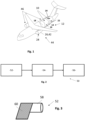
- Fig. 1 shows an aircraft, especially an airplane 44 as an example for a vehicle 12 in which a hydrogen tank 10 is used.
- the airplane 44 has a propulsion system 46 with turbines 42 as engines 26.
- the turbines 42 are configured to burn hydrogen supplied from the hydrogen tank 10.
- the airplane 44 may be equipped with fuel cells (not shown), wherein hydrogen is supplied to the fuel cells from the hydrogen tank 10.
- the hydrogen tank 10 has, e.g., a cylindrical shape.
- the hydrogen tank 10 is configured as a cryogenic tank for storing liquid hydrogen (LH2) at cryogenic temperatures.
- At least one wall component 14 of the tank such as for example the middle cylindrical part 16 or an end cap 18 is made of fibre reinforced composite material.
- the inner surface 20 of the wall component 14 is coated with a cold spray coating 22 of metallic material.
- the inner surface 20 is the surface having contact with the LH2.
- Fig. 2 shows a schematic block diagram of a manufacturing apparatus 50 for manufacturing the hydrogen tank 10.
- the manufacturing apparatus 50 comprises a wall component manufacturing unit 52, a cold spray coating unit 54 and a tank assembly unit 56.
- the wall component manufacturing unit 52 is configured for manufacturing the wall component 14 made from fibre reinforced composite material.
- the cold spray coating unit 54 is configured to apply the coating of metallic material onto at least one surface, especially the inner surface 20, of the wall component 14 by conducting a cold spray process.
- the tank assembly unit 56 is configured to assemble the at least one wall component 14 coated by cold spraying together with further components to form the hydrogen tank 10.
- Fig. 3 shows a schematic perspective view of an example for the wall component manufacturing unit 52.
- the wall component manufacturing unit 52 comprises a winder 58 onto which several layers of CFRP prepregs 60 can be wound in order to achieve the wall component 14.
- Preferred carbon fibre prepreg materials (UD prepregs, i.e. prepregs with unidirectional fibres) and their CTEs are indicated in the following table 1: Table 1: preferred CFRP prepreg materials for production of the wall component 14 Name CTE in fibre direction CTE transversal to fibre direction IMA/M21E 0.15*10 -6 K -1 28.7*10 -6 K -1 HTS/913 3.4*10 -6 K -1 34*10 -6 K -1 HTA/EH25 3.4*10 -6 K -1 34*10 -6 K -1 IM7/M20 3.4*10 -6 K -1 34*10 -6 K -1 T800/M21 2.3*10 -6 K -1 34*10 -6 K -1
- the final wall component 14 has typically a linear CTEc in the area up to 10*10 -6 K -1 .
- a wall component 14 is achieved having a CTEc with 2*10 -6 K -1 ⁇ CTEc ⁇ 34*10 -6 K -1 , preferably 5*10 -6 K -1 ⁇ CTE C ⁇ 15*10 -6 K -1 , most preferred 9*10 -6 K -1 ⁇ CTEc ⁇ 10*10 -6 K -1 .
- the wall component 14 is preferably manufactured with a wall thickness of at least 4 mm or more.
- Fig. 4 shows a schematic view of an embodiment of the cold spray unit 54 together with the wall component 14 to be coated by cold spraying.
- the wall component 14 is manufactured and provided as an essentially cylindrical wall element with polar openings 62.
- the cold spray unit 54 comprises a robotic arm 64 adapted and configured to pass through the polar opening 64 and equipped with a cold spray head 66 as generally known, for example from [3] to [7].
- the cold spray unit 54 is configured to coat the inner surface of the hydrogen tank 10 through the polar openings 62 by a cold spray process with a metallic material.
- the Cold Spray process comprises the following steps:
- the CTE M of the metallic material is lower than the CTEc of the wall component.
- metals or metal alloys are preferred having an CTE M ⁇ 9*10 -6 K -1 .
- Examples for CTE of different materials are indicated in [8].
- powder from metallic material is used which has a linear thermal expansion coefficient CTE M with -30*10 -6 K -1 ⁇ CTE M ⁇ 9*10 -6 K -1 .
- Allvar ® is a metallic alloy that is commercial available and has a negative CTE M .
- the cold spray process is conducted with the following parameters:
- the hydrogen tank 10 is assembled in the tank assembly unit 56 in a conventional manner by mounting further tank or system components to the wall component 14.
- the wall component 14 is configured as a basic structure 68 and as a structural support 70 of the tank 10.
- the polar openings 62 can be closed by end caps 18 (not shown in Fig. 4 ).
- Further hydrogen system components such as pipes, ducts, ventils, thermal isolation, structural support components and so on (not shown) are mounted.
- Fig. 5 shows a schematic view of a first and second wall component 14 for the hydrogen tank 10 according to another embodiment.
- Fig. 6 shows a schematic view of another embodiment of the cold spray unit 54 conducting a cold spray coating of the wall component 14 according to the further embodiment of the manufacturing method for the hydrogen tank 10.
- Fig. 7 shows at least a part of an embodiment of the tank assembly unit 58 during assembly of tank components.
- a first and second wall component 14 form two halves of the basic structure 68.
- the basic structure 68 can be manufactured in the wall component manufacturing unit 52 as one part - essentially as described above with reference to Figs. 3 and 4 -and can then be divided into several parts, for example two halves, as indicated with a dividing line 72.
- the several parts, for example the two halves, which each constitute a wall component 14 of the hydrogen tank 10 can be manufactured separately and can be provided separately to the cold spray unit 54 which is shown in Fig. 6 .
- the cold spray coating can be applied through the large opening 74 of the first and second wall component 14, respectively (the large opening 74 is defined at the dividing line 72 in Fig. 5 ).
- the robotic arm 64 does not need to be configured to reach through the small polar opening 62 as in the embodiment of Fig. 4 .
- the coated wall components 14 can then be assembled (with their large openings 74 put together) in the tank assembly unit 58.
- the first and second halve of the basic structure 68 are mounted together and wrapped with additional layers of the CFRP prepreg 60 until a predefined wall thickness of the basic structure 68 of the hydrogen tank 10 is achieved.
Landscapes
- Engineering & Computer Science (AREA)
- Mechanical Engineering (AREA)
- General Engineering & Computer Science (AREA)
- Filling Or Discharging Of Gas Storage Vessels (AREA)
Abstract
a) providing at least one wall component (14) made from fibre reinforced composite material,
b) coating the at least one wall component (14) with a metallic material by a cold spray process, and
c) using the at least one wall component (14) to form the hydrogen tank wall.
Description
- The invention relates to a manufacturing method for manufacturing a hydrogen tank wall, especially a cryogenic tank wall. Further, the invention relates to a hydrogen tank, especially a cryogenic tank, for a vehicle, especially an aircraft, comprising a tank wall component having a substrate of fibre reinforced composite material. Still further, the invention relates to a manufacturing apparatus for manufacturing a hydrogen tank, especially a cryogenic tank.
- For the technical background of the invention, reference is made to the following citations:
- [1]
US 2015/0 336 680 A1 - [2]
EP 3 498 664 B1 - [3]
FR 3 048 980 A1 - [4]
EP 2 027 305 B1 - [5]
EP 3 401 419 B1 - [6]
US 11 167 864 B2 - [7] Cold spraying - Wikipedia, downloaded on 13.05.2022 from https://en.wikipedia.org/wiki/Cold_spraying
- [8] Thermal Expansion - Wikipedia, downloaded on 25.05.2022 from https://en.wikipedia.org/wiki/Thermal_expansion
- Cryogenic storage tanks may be used for storing liquid hydrogen, for example, for use as a fuel for driving a vehicle. The vehicle may be a motor vehicle such as a car, lorry or train or may be an aircraft. Citations [1] and [2] disclose a tank for the cryogenic storage of hydrogen and an aircraft with a tank installed therein. Liquid hydrogen stored within the tank is used as a fuel for the aircraft engine in place of carbon-based fuels such as kerosene. The cryogenic storage tank is typically substantially cylindrical and includes openings for allowing the tank to be filled with hydrogen as well as to supply the stored liquid hydrogen to the engine.
- Lightweight energy storage is a key topic for next generation aircrafts. Storage systems with high energy density are one of the key challenges for future electrical propulsion-based systems. Different energy storage systems are available today, whereas pressurized (~700 bar) or cryogenic Hydrogen (14 K < T < 21 K) paired with fuel cells or direct burn are interesting solutions for next flight vehicles. Hydrogen (H2) is the molecule with lowest density and smallest diameter in nature, which is why the storage in tanks is very complex and hardly achievable without leakage over longer durations.
- Hydrogen offers high energy densities, whereas the storage technique (cryogenic, compressed, solid state/absorbed) is a key issue. Hydrogen can be compressed and/or cooled down to cryogenic temperatures to increase the volumetric and gravimetric energy density. Usually, complex tank systems are needed with individual requirements to the materials, design and working principle e.g., regarding operational safety.
- Compressed and cryogenic hydrogen are the techniques of choice for today's vehicles, like cars or airplanes. Cryogenic tanks can achieve the lowest added weight wherein, with the present known technologies, about 0.2 kg - 0.5 kg tank weight is needed per kg stored H2. Conventional tanks work with applied inner pressure to avoid gas ingress from outside. As tank material typically metals, metal alloys and composites are in use. Full composite tanks can be challenging because of the long in-service life of civil aircraft. Hydrogen leakage may also be an issue.
- An object of the invention is to improve leak tightness of hydrogen tanks made of composite material.
- The object is achieved by the subject-matter of the independent claims.
- Preferred embodiments are subject-matters of the dependent claims.
- The invention provides a manufacturing method for manufacturing a hydrogen tank wall, especially a cryogenic tank wall for a tank for storing liquid hydrogen, comprising the steps of:
- a) providing at least one wall component made from fibre reinforced composite material,
- b) coating the at least one wall component with a metallic material by a cold spray process, and
- c) using the at least one wall component to form the hydrogen tank wall.
- Preferably, step b) comprises: cold spraying a metal material having a thermal expansion coefficient that is lower than a thermal expansion component of the reinforced composite material onto at least one surface of the wall component. As a result, the cold spray coating applied to at least one surface of the wall component substrate has a lower CTE as the substrate which is made from composite material.
- Preferably, step a) comprises
a1) providing at least one wall component in a tube shape. - Preferably, step a) comprises
a2) providing at least one wall component with the shape of a cap. - Preferably, step a) comprises
a3) winding a prepreg on a winder in order to form the at least one wall component. - Preferably, step a) comprises
a4) stacking several prepregs with different fibre orientation in order to form the at least one wall component. - Preferably, step a) comprises
a5) combining layers of composite material with different fibre orientations to form the at least one wall component. - Preferably, step a) comprises
a6) providing the at least one wall component having a linear thermal expansion coefficient CTEc with 2*10-6 K-1 ≤ CTEc ≤ 34*10-6 K-1, preferably 5*10-6 K-1 ≤ CTEc ≤ 15*10-6 K-1, most preferred 9*10-6 K-1 ≤ CTEc ≤ 10*10-6 K-1. - Preferably, step a) comprises
a7) providing the at least one wall component made from a CFRP composite material. - Preferably, step b) comprises:
b1) conducting the cold spray process with a powder from metallic material having a linear thermal expansion coefficient CTEM with
-30*10-6 K-1 ≤ CTEM ≤ 9*10-6 K-1. - Preferably, step b) comprises:
b2) using one or several metallic materials from the group consisting of iron alloy, nickel alloy, FeNi36(Invar), FeNi36(extrapure), Fe-29Ni-17CO, wolfram, titan, and negative CTE alloy. - Preferably, step b) comprises:
b3) using a carrier gas from the group consisting of air, inert gas, noble gas, nitrogen, and helium. - Preferably, step b) comprises:
b4) conducting the cold spray process with a gas pressure p with 40 bar ≤ p ≤ 70 bar. - Preferably, step b) comprises:
b5) conducting the cold spray process with a gas temperature T with 750°C ≤ T ≤ 1000°C. - Preferably, step b) comprises:
b6) conducting the cold spray process with a powder having particle diameters pd with 25 µm ≤ pd ≤ 60 µm. - Preferably, step b) comprises:
b7) applying a bonding layer on the composite material surface to be coated and applying the coating by the cold spray process over the bonding layer. - Preferably, step b) comprises:
b8) coating an inner surface of the wall component which forms, in use of the wall component in the cryogenic tank, an inner surface area of the tank. - Preferably, step b) comprises:
b9) conducting the cold spray process with a spray head arranged on a robotic arm. - According to another aspect, the invention provides a hydrogen tank for a vehicle, especially an aircraft, preferably a cryogen tank for storing liquified hydrogen, the hydrogen tank comprising a tank wall component having a substrate of fibre reinforced composite material coated with a cold sprayed metallic material layer.
- Preferably, the metallic material layer has a lower thermal expansion coefficient as the fibre-reinforced composite material layer.
- Preferably, the fibre-reinforced composite material substrate has a linear thermal expansion coefficient CTEc with 2*10-6 K-1 ≤ CTEC ≤ 34*10-6 K-1, more preferably 5*10-6 K-1 ≤ CTEc ≤ 15*10-6 K-1, most preferred 9*10-6 K-1 ≤ CTEc ≤ 10*10-6 K-1 and/or wherein the metallic material of the coating has a linear thermal expansion coefficient CTEM with
-30*10-6 K-1 ≤ CTEM ≤ 9*10-6 K-1 - Preferably, the wall component has an inner surface defining a portion of the inner tank surface coated with the cold sprayed metallic material.
- Preferably, the hydrogen tank is achieved by the manufacturing method according to any of the aforementioned embodiments.
- According to another aspect, the invention provides a vehicle, especially an aircraft, comprising a hydrogen tank according to any of the aforementioned embodiments.
- According to another aspect, the invention provides a manufacturing apparatus for manufacturing a hydrogen tank, especially a cryogen tank for storing liquid hydrogen (LH2) comprising
- a wall component manufacturing unit for manufacturing a wall component made from fibre reinforced composite material,
- a cold spray coating unit configured to apply a coating of a metallic material onto at least one surface of the wall component by conducting a cold spray process, and
- a tank assembly unit configured to assemble the at least one wall component coated by cold spraying together with further components to form the hydrogen tank.
- Preferred embodiments of the invention relate to a cold spray inner coating for H2-tanks. Preferably, the proposed coating relates to an application for a tank containing cryogenic fluids (H2). Therefore, an application within hydrogen powered aircrafts is possible.
- Tank structures for cryogenic fluids like liquid H2 are often manufactured from metallic material. For an aeronautical application these tanks are too heavy. The use of composite material for cryogenic tanks results in much lighter structures. But due to the different thermal expansion coefficients of fibre and matrix material microcracks in the matrix material can occur. These cracks will result in an increased loss rate of liquid hydrogen.
- The Cold Spray process enables the coating of composite parts with metallic material. This will create a crack resistant coating.
- As defined in [7], cold spraying (CS) - also called gas dynamic cold spraying - is a coating deposition method in which solid powders (1 to 50 micrometers in diameter) are accelerated in a supersonic gas jet to velocities up to ca. 1200 m/s, wherein, during impact with the substrate, particles undergo plastic deformation and adhere to the surface.
- To achieve a uniform thickness the spraying nozzle is scanned along the substrate. Metals, polymers, ceramics, composite materials and nanocrystalline powders can be deposited using cold spraying. The kinetic energy of the particles, supplied by the expansion of the gas, is converted to plastic deformation energy during bonding. Unlike thermal spraying techniques, e.g., plasma spraying, arc spraying, flame spraying, or high velocity oxygen fuel (HVOF), the powders are not melted during the spraying process. For further details to cold spraying reference is made to citations [3] to [7]. As indicated and explained in [5] and [6], it is also possible to coat fibre reinforced composite materials such as CFRP (carbon fibre reinforced plastic) with a metallic material by using cold spraying.
- As can be noted therefrom, cold spray coatings differ from coatings made with other coating deposition processes.
- By the cold spray process, the powder particles undergo a plastic deformation. The particles are cold-welded to the substrate being coated. The metallic surface achieved by the cold spraying is under compressive stress. Cracks in the composite tank wall component are closed and pressed shut by this compression. Hence, the leak tightness is improved.
- Most preferred, the coating is applied onto at least one surface, preferably the inner surface or inside surface of a tank wall component for a cryogenic H2 tank.
- Using a metallic material with a lower thermal expansion coefficient than the composite material for coating, an inner surface of a tank structure can be created that will remain in a compressed state when exposed to cryogenic temperatures due to the larger shrinkage of the composite. Due to this, the creation of microcracks in the coating is not possible. This will reduce the leakage rate of liquid hydrogen (H2).
- During the Cold Spray process a metal powder is blasted with supersonic velocity onto a target substrate. This is also applicable for fibre composite substrates. With this process a metallic coating can be applied onto the inner surface of a composite tank. Using preferably metallic material with a low thermal expansion coefficient (e.g. Invar (FeNi)) in combination with a composite material of a higher CTE (Coefficient of Thermal Expansion, see [8]) than the metal, a hybrid tank wall can be created. When exposed to cryogenic temperatures (liquid H2) the composite wall will contract more than the metallic coating. Therefore, the metallic coating will stay in a compressed state. This compressed state of the metallic coating will prevent microcracks. Due to this the leakage rate of H2 can be reduced.
- Preferably, the tank is formed as a tube. For example, the tank has essentially a cylindrical shape. A wall component for such tank can be manufactured by winding a composite material, especially a prepreg, more preferred a CFRP prepreg onto a winding machine (shortly referred to as winder). Thus, a tubelike cylindrical structure with open ends is achieved. Through the open end, a robotic arm with a cold spray head, e.g., such as indicated in [7], can reach the inner surface and apply the cold spray coating onto the inner surface. It is also possible to manufacture several components, e.g., half-shells or two halves of the tank, for example two half spheres or two halves of a cylinder, to coat the inner side thereof and to then assemble these components to arrive at the tank module.
- Preferably, the wall thickness of the composite tank wall component (=target substrate) is at least 4 mm or more. As known from [5] and [6], a bonding layer may be applied first in order to enhance the coating. However, with lower gas pressure, the cold spray coating also works without a bonding layer. For further advantages of the cold spraying, reference is made to [7].
- Preferred embodiments of the invention are explained in more detail below referring to the accompanying drawings in which:
- Fig. 1
- shows a perspective schematic view of an aircraft as an example for a vehicle equipped with a hydrogen tank, especially a cryogenic tank for storing liquid hydrogen (LH2);
- Fig. 2
- shows a schematic block diagram of a manufacturing apparatus for manufacturing the hydrogen tank;
- Fig. 3
- shows a schematic perspective view of an example for a wall component manufacturing unit;
- Fig. 4
- shows a schematic view of a cold spray unit together with a wall component to be coated by cold spraying;
- Fig. 5
- a schematic view of a further embodiment of wall components for the hydrogen tank;
- Fig. 6
- shows a schematic view of the cold spray unit conducting a cold spray coating of the wall component according to an embodiment of a manufacturing method for the hydrogen tank; and
- Fig. 7
- shows at least a part of an embodiment of a tank assembly unit during assembly of tank components.
-
Fig. 1 shows an aircraft, especially anairplane 44 as an example for avehicle 12 in which ahydrogen tank 10 is used. Theairplane 44 has apropulsion system 46 with turbines 42 as engines 26. The turbines 42 are configured to burn hydrogen supplied from thehydrogen tank 10. Further, theairplane 44 may be equipped with fuel cells (not shown), wherein hydrogen is supplied to the fuel cells from thehydrogen tank 10. - The
hydrogen tank 10 has, e.g., a cylindrical shape. Thehydrogen tank 10 is configured as a cryogenic tank for storing liquid hydrogen (LH2) at cryogenic temperatures. At least onewall component 14 of the tank, such as for example the middlecylindrical part 16 or anend cap 18 is made of fibre reinforced composite material. Theinner surface 20 of thewall component 14 is coated with acold spray coating 22 of metallic material. Here, theinner surface 20 is the surface having contact with the LH2. -
Fig. 2 shows a schematic block diagram of amanufacturing apparatus 50 for manufacturing thehydrogen tank 10. Themanufacturing apparatus 50 comprises a wallcomponent manufacturing unit 52, a coldspray coating unit 54 and atank assembly unit 56. The wallcomponent manufacturing unit 52 is configured for manufacturing thewall component 14 made from fibre reinforced composite material. The coldspray coating unit 54 is configured to apply the coating of metallic material onto at least one surface, especially theinner surface 20, of thewall component 14 by conducting a cold spray process. Thetank assembly unit 56 is configured to assemble the at least onewall component 14 coated by cold spraying together with further components to form thehydrogen tank 10. -
Fig. 3 shows a schematic perspective view of an example for the wallcomponent manufacturing unit 52. The wallcomponent manufacturing unit 52 comprises awinder 58 onto which several layers of CFRP prepregs 60 can be wound in order to achieve thewall component 14. - Preferred carbon fibre prepreg materials (UD prepregs, i.e. prepregs with unidirectional fibres) and their CTEs are indicated in the following table 1:
Table 1: preferred CFRP prepreg materials for production of the wall component 14Name CTE in fibre direction CTE transversal to fibre direction IMA/M21E 0.15*10-6 K-1 28.7*10-6 K-1 HTS/913 3.4*10-6 K-1 34*10-6 K-1 HTA/EH25 3.4*10-6 K-1 34*10-6 K-1 IM7/M20 3.4*10-6 K-1 34*10-6 K-1 T800/M21 2.3*10-6 K-1 34*10-6 K-1 - By combining several prepreg layers with different fibre orientation the
final wall component 14 has typically a linear CTEc in the area up to 10*10-6 K-1. For example, awall component 14 is achieved having a CTEc with 2*10-6 K-1 ≤ CTEc ≤ 34*10-6 K-1, preferably 5*10-6 K-1 ≤ CTEC ≤ 15*10-6 K-1, most preferred 9*10-6 K-1 ≤ CTEc ≤ 10*10-6 K-1. By stackingseveral prepreg 60 layers, thewall component 14 is preferably manufactured with a wall thickness of at least 4 mm or more. -
Fig. 4 shows a schematic view of an embodiment of thecold spray unit 54 together with thewall component 14 to be coated by cold spraying. Thewall component 14 is manufactured and provided as an essentially cylindrical wall element withpolar openings 62. Thecold spray unit 54 comprises arobotic arm 64 adapted and configured to pass through thepolar opening 64 and equipped with acold spray head 66 as generally known, for example from [3] to [7]. Thecold spray unit 54 is configured to coat the inner surface of thehydrogen tank 10 through thepolar openings 62 by a cold spray process with a metallic material. - The Cold Spray process comprises the following steps:
- Mixing a metallic powder with gas (Air, inert gas, N2, noble gas or He)
- Powder particles are accelerated by the jet of gas up to supersonic speed
- Powder particles remain in solid state during spraying
- Cold Spray rely only on plastic deformation to build up coatings
- In a preferred embodiment, the CTEM of the metallic material is lower than the CTEc of the wall component. For the metallic coating, metals or metal alloys are preferred having an CTEM < 9*10-6 K-1. Examples for CTE of different materials are indicated in [8]. Preferably, powder from metallic material is used which has a linear thermal expansion coefficient CTEM with -30*10-6 K-1 ≤ CTEM ≤ 9*10-6 K-1. Preferred materials are indicated in the following table 2:
Name CTEM FeNi36 (Invar) 1.2*10-6 K-1 FeNi36 extrapure 0.65*10-6 K-1 Fe-29Ni-17Co 5.5*10-6 K-1 Wolfram 4.5*10-6 K-1 Titan 8.5*10-6 K-1 ALLVAR® negative CTE, -20*10-6 K-1 to -10*10- 6 K-1, also -30*10-6 K-1 possible, see [8] - Allvar® is a metallic alloy that is commercial available and has a negative CTEM.
- Preferably, the cold spray process is conducted with the following parameters:
- Carrier gas: He or N2 preferred
- Gas pressure p: 40 bar to 70 bar
- Gas temperature T: 750°C to 1100°C
- Particle size: 25 µm to 60 µm.
- Using the
wall component 14 being coated by cold spraying as described above, thehydrogen tank 10 is assembled in thetank assembly unit 56 in a conventional manner by mounting further tank or system components to thewall component 14. In the embodiment ofFig. 4 , thewall component 14 is configured as abasic structure 68 and as astructural support 70 of thetank 10. In an assembling step, thepolar openings 62 can be closed by end caps 18 (not shown inFig. 4 ). Further hydrogen system components such as pipes, ducts, ventils, thermal isolation, structural support components and so on (not shown) are mounted. - Referring to
Figs. 5 to 7 , an alternative embodiment for a manufacturing method for thehydrogen tank 10 is described in the following. -
Fig. 5 shows a schematic view of a first andsecond wall component 14 for thehydrogen tank 10 according to another embodiment.Fig. 6 shows a schematic view of another embodiment of thecold spray unit 54 conducting a cold spray coating of thewall component 14 according to the further embodiment of the manufacturing method for thehydrogen tank 10.Fig. 7 shows at least a part of an embodiment of thetank assembly unit 58 during assembly of tank components. - As shown in
Fig. 5 ,several wall components 14 form together thebasic structure 68 of thehydrogen tank 10. In the embodiment shown, a first andsecond wall component 14 form two halves of thebasic structure 68. According to one embodiment, thebasic structure 68 can be manufactured in the wallcomponent manufacturing unit 52 as one part - essentially as described above with reference toFigs. 3 and4 -and can then be divided into several parts, for example two halves, as indicated with adividing line 72. According to another embodiment, the several parts, for example the two halves, which each constitute awall component 14 of thehydrogen tank 10, can be manufactured separately and can be provided separately to thecold spray unit 54 which is shown inFig. 6 . - As shown in
Fig. 6 , the cold spray coating can be applied through thelarge opening 74 of the first andsecond wall component 14, respectively (the large opining 74 is defined at thedividing line 72 inFig. 5 ). Hence, therobotic arm 64 does not need to be configured to reach through the smallpolar opening 62 as in the embodiment ofFig. 4 . - As shown in
Fig. 7 , thecoated wall components 14 can then be assembled (with theirlarge openings 74 put together) in thetank assembly unit 58. In the embodiment shown, the first and second halve of thebasic structure 68 are mounted together and wrapped with additional layers of theCFRP prepreg 60 until a predefined wall thickness of thebasic structure 68 of thehydrogen tank 10 is achieved. - Hence, a manufacturing method for manufacturing a hydrogen tank wall has been described, comprising the steps of:
- a) providing at least one
wall component 14 made from fibre reinforced composite material, - b) coating the at least one
wall component 14 with a metallic material by a cold spray process, and - c) using the at least one
wall component 14 to form the hydrogen tank wall. -
- 10
- hydrogen tank
- 12
- vehicle
- 14
- wall component
- 16
- cylindrical part
- 18
- end cap
- 20
- inner surface
- 22
- cold spray coating
- 26
- engine
- 42
- turbine
- 44
- airplane
- 46
- propulsion system
- 50
- manufacturing apparatus
- 52
- wall component manufacturing unit
- 54
- cold spray unit
- 56
- tank assembly unit
- 58
- winder
- 60
- prepreg
- 62
- polar opening
- 64
- robotic arm
- 66
- cold spray head
- 68
- basic structure
- 70
- structural support
- 72
- dividing line
- 74
- large opining
Claims (10)
- Manufacturing method for manufacturing a hydrogen tank wall, comprising the steps of:a) providing at least one wall component (14) made from fibre reinforced composite material,b) coating the at least one wall component (14) with a metallic material by a cold spray process, andc) using the at least one wall component (14) to form the hydrogen tank wall.
- Manufacturing method according to claim 1, characterized in that step b) comprises: cold spraying the metallic material having a thermal expansion coefficient that is lower than a thermal expansion component of the reinforced composite material onto at least one surface (20) of the wall component (14).
- Manufacturing method according to any one of the preceding claims, characterized in that step a) comprises at least one or several of the steps:a1) providing at least one wall component (14) in a tube shape,a2) providing at least one wall component (14) with the shape of a cap,a3) winding a prepreg (60) on a winder (58) in order to form the at least one wall component (14),a4) stacking several prepregs (60) with different fibre orientation in order to form the at least one wall component (14),a5) combining layers of composite material with different fibre orientations to form the at least one wall component (14),a6) providing the at least one wall component (14) having a linear thermal expansion coefficient CTEc with 2*10-6 K-1 ≤ CTEc ≤ 34*10-6 K-1, preferably 5*10-6 K-1 ≤ CTEc ≤ 15*10-6 K-1, most preferred 9*10-6 K-1 ≤ CTEc ≤ 10*10-6 K-1,a7) providing the at least one wall component (14) from a CFRP composite material.
- Manufacturing method according to any of the preceding claims, characterized in that step b) comprises at least one or several of the steps:b1) conducting the cold spray process with a powder from metallic material having a linear thermal expansion coefficient CTEM with
-30*10-6 K-1 ≤ CTEM ≤ 9*10-6 K-1b2) using one or several metallic materials from the group consisting of iron alloy, nickel alloy, FeNi36(Invar), FeNi36(extrapure), Fe-29Ni-17CO, wolfram, titan, and negative CTE alloy,b3) using a carrier gas from the group consisting of air, inert gas, noble gas, nitrogen, and helium;b4) conducting the cold spray process with a gas pressure p with 40 bar ≤ p ≤ 70 bar,b5) conducting the cold spray process with a gas temperature T with 750°C ≤ T ≤ 1000°C;b6) conducting the cold spray process with a powder having particle diameters pd with 25 µm ≤ pd ≤ 60 µm;b7) applying a bonding layer on the composite material surface to be coated and applying the coating by the cold spray process over the bonding layer;b8) coating an inner surface (20) of the wall component (14) which forms, in use of the wall component in the hydrogen tank (10), an inner surface area of the tank (10);b9) conducting the cold spray process with a cold spray head (66) arranged on a robotic arm (54). - Hydrogen tank (10) for a vehicle (12), especially an aircraft, comprising a tank wall component (14) having a substrate of fibre reinforced composite material coated with a cold sprayed metallic material layer.
- Hydrogen tank (10) according to claim 5, wherein the metallic material layer has a lower thermal expansion coefficient as the fibre-reinforced composite material substrate.
- Hydrogen tank (10) according to claim 5 or 6, wherein the fibre-reinforced composite material substrate has a linear thermal expansion coefficient CTEc with 2*10-6 K-1 ≤ CTEc ≤ 34*10-6 K-1, preferably 5*10-6 K-1 ≤ CTEc ≤ 15*10-6 K-1, most preferred 9*10-6 K-1 ≤ CTEc ≤ 10*10-6 K-1 and/or wherein the metallic material of the coating has a linear thermal expansion coefficient CTEM with
-30*10-6 K-1 ≤ CTEM ≤ 9*10-6 K-1 - Hydrogen tank according to any of the claims 5 to 7, wherein the wall component (14) has an inner surface (20) defining a portion of the inner tank surface coated with the cold sprayed metallic material.
- Vehicle (12), especially aircraft, comprising a hydrogen tank (10) according to any of the claims 5 to 9.
- Manufacturing apparatus (50) for manufacturing a hydrogen tank (10), comprisinga wall component manufacturing unit (52) for manufacturing a wall component (14) made from fibre reinforced composite material,a cold spray coating unit (54) configured to apply a coating of a metallic material onto at least one surface (20) of the wall component (14) by conducting a cold spray process, anda tank assembly unit (56) configured to assemble the at least one wall component (14) coated by cold spraying together with further components to form the hydrogen tank (10).
Priority Applications (1)
| Application Number | Priority Date | Filing Date | Title |
|---|---|---|---|
| EP22177002.7A EP4286740A1 (en) | 2022-06-02 | 2022-06-02 | Method and apparatus for manufacturing a hydrogen tank wall, and wall component for such tank wall |
Applications Claiming Priority (1)
| Application Number | Priority Date | Filing Date | Title |
|---|---|---|---|
| EP22177002.7A EP4286740A1 (en) | 2022-06-02 | 2022-06-02 | Method and apparatus for manufacturing a hydrogen tank wall, and wall component for such tank wall |
Publications (1)
| Publication Number | Publication Date |
|---|---|
| EP4286740A1 true EP4286740A1 (en) | 2023-12-06 |
Family
ID=81877897
Family Applications (1)
| Application Number | Title | Priority Date | Filing Date |
|---|---|---|---|
| EP22177002.7A Withdrawn EP4286740A1 (en) | 2022-06-02 | 2022-06-02 | Method and apparatus for manufacturing a hydrogen tank wall, and wall component for such tank wall |
Country Status (1)
| Country | Link |
|---|---|
| EP (1) | EP4286740A1 (en) |
Cited By (1)
| Publication number | Priority date | Publication date | Assignee | Title |
|---|---|---|---|---|
| US12601299B1 (en) * | 2025-04-16 | 2026-04-14 | General Electric Company | Hydrogen fuel system for an aircraft |
Citations (1)
| Publication number | Priority date | Publication date | Assignee | Title |
|---|---|---|---|---|
| DE202020106328U1 (en) * | 2019-11-08 | 2021-02-10 | Additive Space Gmbh | container |
-
2022
- 2022-06-02 EP EP22177002.7A patent/EP4286740A1/en not_active Withdrawn
Patent Citations (1)
| Publication number | Priority date | Publication date | Assignee | Title |
|---|---|---|---|---|
| DE202020106328U1 (en) * | 2019-11-08 | 2021-02-10 | Additive Space Gmbh | container |
Non-Patent Citations (2)
| Title |
|---|
| "Cold spraying", WIKIPEDIA, 13 May 2022 (2022-05-13), Retrieved from the Internet <URL:https://en.wikipedia.org/wiki/Cold_spraying> |
| "Thermal Expansion", WIKIPEDIA, 25 May 2022 (2022-05-25), Retrieved from the Internet <URL:https://en.wikipedia.org/wiki/Thermal_expansion> |
Cited By (1)
| Publication number | Priority date | Publication date | Assignee | Title |
|---|---|---|---|---|
| US12601299B1 (en) * | 2025-04-16 | 2026-04-14 | General Electric Company | Hydrogen fuel system for an aircraft |
Similar Documents
| Publication | Publication Date | Title |
|---|---|---|
| US20230332742A1 (en) | Method for coating a wall | |
| EP4269653B1 (en) | Molding composite part with metal layer | |
| US11559964B2 (en) | Composite structures, composite storage tanks, vehicles including such composite storage tanks, and related systems and methods | |
| EP1129787B1 (en) | Coatings on fiber reinforced composites | |
| US8052074B2 (en) | Apparatus and process for depositing coatings | |
| US20090098286A1 (en) | Method for forming bond coats for thermal barrier coatings on turbine engine components | |
| WO1997028401A1 (en) | High-performance, thin metal-lined, composite overwrapped pressure vessel | |
| Doorbar et al. | 4.19 development of continuously-reinforced metal matrix composites for aerospace applications | |
| CN102027150A (en) | Method for coating fiber composite parts for spacecraft or aircraft and fiber composite parts produced by the method | |
| Hu et al. | Surface repair of aircraft titanium alloy parts by cold spraying technology | |
| CN116837315B (en) | A method for preparing a high-hardness, high-temperature steam oxidation resistant composite coating | |
| CN114752881B (en) | Preparation method of thermal barrier coating resistant to CMAS corrosion and thermal barrier coating obtained thereby | |
| Cao et al. | Application and prospect of 3D printing technology in aerospace | |
| US11453147B2 (en) | Method for producing a composite component formed with a fibre-reinforced plastic component on which at least one surface with a coating is formed | |
| US7419704B2 (en) | Coatings on fiber reinforced composites | |
| CN101914745B (en) | Method for preparing ZnAl alloy lining composite pressure vessel by adopting electric arc spraying | |
| CN101914744B (en) | Method for preparing composite material pressure container with PbSn alloy lining by plasma spray | |
| EP4438287A1 (en) | Storage tank for liquified gas, aircraft or spacecraft comprising such a storage tank, and fibre metal laminates | |
| RU2421429C2 (en) | Composite multilayer materials, methods of making cowling, cut off half-sphere, shell, half-shell and apparatus for realising said methods | |
| Perna et al. | Fused filament fabrication of ONYX-based composites coated with aluminum powders: a preliminary analysis on feasibility and characterization | |
| US20260117927A1 (en) | Composite storage tank for liquid hydrogen and methods of manufacturing | |
| CN115627439B (en) | Dense thick alloy coating without layered structure and preparation method thereof | |
| US20240043125A1 (en) | Manufacturing method for manufacturing a profile rail, profile rail obtainable thereby, mounting system and vehicle equipped therewith and use of the profile rail | |
| Hauer et al. | A novel design approach: increase in storage and transport efficiency for liquid hydrogen by using a dual concept involving a steel-fiber composite tank and thermal sprayed insulating coatings | |
| Archambault | Lay-up Moulding of a Carbon Fiber Reinforced Polymer Composite on a Cold Sprayed Metallic Layer |
Legal Events
| Date | Code | Title | Description |
|---|---|---|---|
| PUAI | Public reference made under article 153(3) epc to a published international application that has entered the european phase |
Free format text: ORIGINAL CODE: 0009012 |
|
| STAA | Information on the status of an ep patent application or granted ep patent |
Free format text: STATUS: THE APPLICATION HAS BEEN PUBLISHED |
|
| AK | Designated contracting states |
Kind code of ref document: A1 Designated state(s): AL AT BE BG CH CY CZ DE DK EE ES FI FR GB GR HR HU IE IS IT LI LT LU LV MC MK MT NL NO PL PT RO RS SE SI SK SM TR |
|
| STAA | Information on the status of an ep patent application or granted ep patent |
Free format text: STATUS: REQUEST FOR EXAMINATION WAS MADE |
|
| 17P | Request for examination filed |
Effective date: 20240606 |
|
| RBV | Designated contracting states (corrected) |
Designated state(s): AL AT BE BG CH CY CZ DE DK EE ES FI FR GB GR HR HU IE IS IT LI LT LU LV MC MK MT NL NO PL PT RO RS SE SI SK SM TR |
|
| STAA | Information on the status of an ep patent application or granted ep patent |
Free format text: STATUS: THE APPLICATION IS DEEMED TO BE WITHDRAWN |
|
| 18D | Application deemed to be withdrawn |
Effective date: 20240607 |