EP4286716A1 - Proportional hydrogen solenoid valve - Google Patents
Proportional hydrogen solenoid valve Download PDFInfo
- Publication number
- EP4286716A1 EP4286716A1 EP22383321.1A EP22383321A EP4286716A1 EP 4286716 A1 EP4286716 A1 EP 4286716A1 EP 22383321 A EP22383321 A EP 22383321A EP 4286716 A1 EP4286716 A1 EP 4286716A1
- Authority
- EP
- European Patent Office
- Prior art keywords
- solenoid valve
- mobile core
- core
- slider
- valve according
- Prior art date
- Legal status (The legal status is an assumption and is not a legal conclusion. Google has not performed a legal analysis and makes no representation as to the accuracy of the status listed.)
- Granted
Links
Images

Classifications
-
- F—MECHANICAL ENGINEERING; LIGHTING; HEATING; WEAPONS; BLASTING
- F16—ENGINEERING ELEMENTS AND UNITS; GENERAL MEASURES FOR PRODUCING AND MAINTAINING EFFECTIVE FUNCTIONING OF MACHINES OR INSTALLATIONS; THERMAL INSULATION IN GENERAL
- F16K—VALVES; TAPS; COCKS; ACTUATING-FLOATS; DEVICES FOR VENTING OR AERATING
- F16K39/00—Devices for relieving the pressure on the sealing faces
- F16K39/02—Devices for relieving the pressure on the sealing faces for lift valves
- F16K39/024—Devices for relieving the pressure on the sealing faces for lift valves using an auxiliary valve on the main valve
-
- F—MECHANICAL ENGINEERING; LIGHTING; HEATING; WEAPONS; BLASTING
- F02—COMBUSTION ENGINES; HOT-GAS OR COMBUSTION-PRODUCT ENGINE PLANTS
- F02M—SUPPLYING COMBUSTION ENGINES IN GENERAL WITH COMBUSTIBLE MIXTURES OR CONSTITUENTS THEREOF
- F02M21/00—Apparatus for supplying engines with non-liquid fuels, e.g. gaseous fuels stored in liquid form
- F02M21/02—Apparatus for supplying engines with non-liquid fuels, e.g. gaseous fuels stored in liquid form for gaseous fuels
- F02M21/0203—Apparatus for supplying engines with non-liquid fuels, e.g. gaseous fuels stored in liquid form for gaseous fuels characterised by the type of gaseous fuel
- F02M21/0206—Non-hydrocarbon fuels, e.g. hydrogen, ammonia or carbon monoxide
-
- F—MECHANICAL ENGINEERING; LIGHTING; HEATING; WEAPONS; BLASTING
- F02—COMBUSTION ENGINES; HOT-GAS OR COMBUSTION-PRODUCT ENGINE PLANTS
- F02M—SUPPLYING COMBUSTION ENGINES IN GENERAL WITH COMBUSTIBLE MIXTURES OR CONSTITUENTS THEREOF
- F02M21/00—Apparatus for supplying engines with non-liquid fuels, e.g. gaseous fuels stored in liquid form
- F02M21/02—Apparatus for supplying engines with non-liquid fuels, e.g. gaseous fuels stored in liquid form for gaseous fuels
- F02M21/0218—Details on the gaseous fuel supply system, e.g. tanks, valves, pipes, pumps, rails, injectors or mixers
- F02M21/023—Valves; Pressure or flow regulators in the fuel supply or return system
-
- F—MECHANICAL ENGINEERING; LIGHTING; HEATING; WEAPONS; BLASTING
- F02—COMBUSTION ENGINES; HOT-GAS OR COMBUSTION-PRODUCT ENGINE PLANTS
- F02M—SUPPLYING COMBUSTION ENGINES IN GENERAL WITH COMBUSTIBLE MIXTURES OR CONSTITUENTS THEREOF
- F02M21/00—Apparatus for supplying engines with non-liquid fuels, e.g. gaseous fuels stored in liquid form
- F02M21/02—Apparatus for supplying engines with non-liquid fuels, e.g. gaseous fuels stored in liquid form for gaseous fuels
- F02M21/0218—Details on the gaseous fuel supply system, e.g. tanks, valves, pipes, pumps, rails, injectors or mixers
- F02M21/0248—Injectors
- F02M21/0257—Details of the valve closing elements, e.g. valve seats, stems or arrangement of flow passages
- F02M21/026—Lift valves, i.e. stem operated valves
- F02M21/0263—Inwardly opening single or multi nozzle valves, e.g. needle valves
- F02M21/0266—Hollow stem valves; Piston valves; Stems having a spherical tip
-
- F—MECHANICAL ENGINEERING; LIGHTING; HEATING; WEAPONS; BLASTING
- F16—ENGINEERING ELEMENTS AND UNITS; GENERAL MEASURES FOR PRODUCING AND MAINTAINING EFFECTIVE FUNCTIONING OF MACHINES OR INSTALLATIONS; THERMAL INSULATION IN GENERAL
- F16K—VALVES; TAPS; COCKS; ACTUATING-FLOATS; DEVICES FOR VENTING OR AERATING
- F16K1/00—Lift valves or globe valves, i.e. cut-off apparatus with closure members having at least a component of their opening and closing motion perpendicular to the closing faces
- F16K1/32—Details
- F16K1/52—Means for additional adjustment of the rate of flow
- F16K1/523—Means for additional adjustment of the rate of flow for limiting the maximum flow rate, using a stop
-
- F—MECHANICAL ENGINEERING; LIGHTING; HEATING; WEAPONS; BLASTING
- F16—ENGINEERING ELEMENTS AND UNITS; GENERAL MEASURES FOR PRODUCING AND MAINTAINING EFFECTIVE FUNCTIONING OF MACHINES OR INSTALLATIONS; THERMAL INSULATION IN GENERAL
- F16K—VALVES; TAPS; COCKS; ACTUATING-FLOATS; DEVICES FOR VENTING OR AERATING
- F16K31/00—Actuating devices; Operating means; Releasing devices
- F16K31/02—Actuating devices; Operating means; Releasing devices electric; magnetic
- F16K31/06—Actuating devices; Operating means; Releasing devices electric; magnetic using a magnet, e.g. diaphragm valves, cutting off by means of a liquid
- F16K31/0644—One-way valve
- F16K31/0655—Lift valves
Definitions
- adjustment means are provided that are configured to adjust the path of motion of the mobile core (2) in order to obtain a suitable or required positioning for optimal operation of the solenoid valve.
Landscapes
- Engineering & Computer Science (AREA)
- General Engineering & Computer Science (AREA)
- Chemical & Material Sciences (AREA)
- Mechanical Engineering (AREA)
- Chemical Kinetics & Catalysis (AREA)
- General Chemical & Material Sciences (AREA)
- Oil, Petroleum & Natural Gas (AREA)
- Combustion & Propulsion (AREA)
- Physics & Mathematics (AREA)
- Fluid Mechanics (AREA)
- Magnetically Actuated Valves (AREA)
Abstract
Description
- The aim of this application is to provide a proportional hydrogen solenoid valve for hydrogenfueled engines and hydrogen fuel cell vehicles.
- More specifically, the invention proposes the development of a proportional hydrogen solenoid valve intended to withstand high working pressures without needing to oversize the body of the solenoid valve, having means to facilitate the movement of the elements involved in the opening and closing actions of the valve to allow hydrogen to flow.
- In the automotive sector, proportional-type solenoid valves intended to regulate the pressure and flow of a fluid are well-known on the market, said valves essentially comprising a fixed core and a mobile core that can move axially relative to said fixed core by the force of a magnetic field created by the electric current of a coil, thereby allowing fluid communication between inlet and outlet ports.
- However, the previously described solenoid valves used for the flow of a cooling fluid, for example, do not require high pressures, and thus their design is not initially intended to withstand pressures of 20 bars, for example, as is required if the fluid is hydrogen. This also affects the materials and the design of the sealing means, which are also not designed to work with this pressure range and are therefore not suitable for the flow of hydrogen.
- Document
ES 1271974 claim 1, is known. Although the solenoid valve described in the aforementioned document solves the previous problem, in practice it has been observed that it is possible to improve its operative efficiency and simplify its construction process. - Furthermore, the applicant is currently unaware of an invention that has all the features described in this specification.
- The present invention has been developed with the aim of providing a proportional solenoid valve intended for a hydraulic circuit through which hydrogen flows, which is configured as a novelty within the field of application and solves the aforementioned drawbacks, also providing other additional advantages which will be apparent from the accompanying description below.
- An object of the present invention is therefore to provide a proportional hydrogen solenoid valve, intended to regulate the flow of hydrogen, of the type comprising a fixed core and a mobile core that can move axially through a hole relative to said fixed core by the force of a magnetic field created by a coil, in which primary elastic return means linked to the mobile core and secondary elastic means linked to sealing means are provided to allow fluid to flow through inlet and outlet ports, in which the sealing means are located in a slider that is moved by the movement of the mobile core.
- Particularly, the invention is characterized in that the slider is made up of a substantially cylindrical body defined by a first portion facing the mobile core and a second portion oriented towards the inlet and outlet ports for the circulating fluid, in which the first portion comprises a series of annular recesses and a cavity at the end facing the mobile core, wherein a sealing element coupled to the mobile core can be inserted, in which the second portion comprises a substantially cylindrical recessed cross section in which the second elastic means are inserted, the first portion having a larger external diameter than the second portion, and in which the slider has a termination at the free end of the second portion, said termination made up of a frustoconical section from which a cylindrical extension extends, intended to seal the outlet.
- Thanks to these features, the reliability and operation of the solenoid valve are increased by improving aspects related to the slider, which is an important component in the operation. This new design makes it possible to eliminate the use of a PTFE sealing ring, hitherto used in similar designs, and thus reduces the friction of the slider with respect to the valve body as well as the manufacturing costs by reducing the number of components. Another advantageous aspect is that, due to the new configuration, the location of the second elastic means prevents a possible blockage of the elastic means (usually a helical spring), thereby increasing the useful life of the elastic means.
- According to another aspect of the invention, a casing is provided to house the fixed core and the mobile core, having a sealing plug that is linked to the fixed core, in which the plug has an extension that extends towards the inside of the casing provided with a threaded portion able to be coupled to a threaded portion on the fixed core.
- Advantageously, the mobile core comprises a substantially cylindrical solid body with a central blind hole in which the primary elastic return means are housed, and a sealing element comprising a protruding projection that extends from the face of the mobile core that faces the slider.
- Additionally, a washer is provided that is housed at the end of the mobile core facing the fixed core, the housing being formed by a centrally protruding enlargement around the rim of the blind hole.
- Advantageously, the washer is made of a metallic material, the inner diameter thereof defined by two projecting planes that converge with each other at half the height of the total height of the washer, said planes having dimensions that are complementary to the inner part of the enlargement.
- The slider is preferably made of aluminum or an aluminum alloy, given that it is a light material, which allows for a fast actuation speed during the opening and closing operations.
- The mobile core and the fixed core are also preferably made of ferritic stainless steel. This prevents or reduces corrosion, since hydrogen is an inert gas. The formation of corrosion directly affects the movement of the mobile core and, consequently, the correct functioning of the solenoid valve.
- The proportional solenoid valve described thus represents an innovative structure with structural and constituent features hitherto unknown for the purpose for which it is intended, a fact which, along with its practical utility, provides it with sufficient grounds to obtain the requested exclusivity privilege.
- Another aspect of the invention is that the inlets and the outlet are arranged perpendicularly to each other, wherein the outlet is defined by a tube, one end of which is flush with the position of the inlets. This reduces the changes in the direction of hydrogen flow, thus reducing pressure loss.
- Other features and advantages of the proportional solenoid valve object of the present invention will become apparent from the description of a preferred, but not exclusive, embodiment, which is illustrated by way of non-limiting example in the accompanying drawings, wherein:
-
- Figure 1 is a perspective view of an embodiment of the solenoid valve according to the present invention;
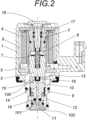
- Figure 2 is an enlarged cross-sectional elevation view of the proportional solenoid valve in an electrically disconnected state, corresponding to the closed position; and
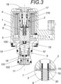
- Figure 3 is an enlarged cross-sectional elevation view of the proportional solenoid valve in an electrically powered state, corresponding to the open position.
- In light of the aforementioned figures and, according to the numbering adopted, a preferred exemplary embodiment of the invention can be seen in them, which comprises the parts and elements indicated and described in detail below.
- In the embodiment represented, the proportional hydrogen solenoid valve is intended to regulate the flow of hydrogen and comprises an outer casing (1), a fixed core (2) and a mobile core (3) that can move axially through a hole relative to said fixed core (2) by the force of a magnetic field created by the electric current in a coil (4) mounted on a coil holder (5) and externally encased or protected by a coil core (6).
- Furthermore, primary elastic return means linked to the mobile core and secondary elastic means linked to sealing means are provided to allow fluid to flow through inlet ports (12) and an outlet port (11), wherein the sealing means are located in a slider that is moved by the movement of the mobile core.
- Another noteworthy aspect is that the inlet direction of the flow of hydrogen into the inlet ports (12) is perpendicular to the outlet direction defined by the outlet port (11), the inlet ports (12) being radially distributed above the outlet port (11).
- The casing in which the fixed core and the mobile core are housed, has a sealing plug (18) at one end that is linked to the fixed core (2), wherein the plug has an extension that extends towards the inside of the casing (1) provided with a threaded portion able to be coupled to a threaded portion on the fixed core (2).
- Additionally, a compensation chamber (13) is provided to compensate the flow pressure with the aim of facilitating and assisting the movement of the mobile core (3) and is located between the mobile core (3) and the slider (10), in fluid communication with an area where the inlet (12) and outlet (11) ports are located by means of a passage (14) that runs longitudinally inside the slider (10).
- In particular reference to the slider (10), the same is made up of a substantially cylindrical body defined by a first portion facing the mobile core and a second portion oriented towards the inlet and outlet ports for the circulating fluid, in which the first portion comprises a series of annular recesses and a cavity (100) at the end facing the mobile core, wherein a sealing element coupled to the mobile core can be inserted, in which the second portion comprises a substantially cylindrical recessed cross section in which the second elastic means are inserted, the first portion having a larger external diameter than the second portion, and in which the slider has a termination at the free end of the second portion, said termination made up of a frustoconical section (101) from which a cylindrical terminal extension (102) extends, intended to seal the outlet (11).
- The mobile core (3) comprises a substantially cylindrical solid body with a central blind hole (30) in which the primary elastic return means are housed, and a sealing element (15) comprising a protruding projection that extends from the face of the mobile core (3) that faces the slider (10) and which includes a polymer coating (19), such as rubber.
- The primary elastic return means, which help the mobile core return to its original position when the valve is deactivated, consist of a helical spring (8), while the secondary elastic means, provided to assist the movement of the slider (10), are also made up of a helical spring (9) housed in a cavity inside the slider (10).
- A washer (7) is housed at the end of the mobile core (3) that faces the fixed core, the housing being formed by a centrally protruding enlargement around the rim of the blind hole.
- In further reference to the washer (7), the same is made of a metallic material and the inner diameter thereof is defined by two projecting planes (70) that converge with each other at half the height of the total height of the washer (7), said planes having dimensions that are complementary to the inner part of the enlargement, as can be seen in the enlarged detail in figure 3.
- Additionally, adjustment means are provided that are configured to adjust the path of motion of the mobile core (2) in order to obtain a suitable or required positioning for optimal operation of the solenoid valve.
- Now, relating to these adjustment means, the same comprise a screw (17) with an upper head hidden under the sealing plug (18) and a rod with a threaded region (170) intended to be coupled to the fixed core (2), thereby allowing the position of the fixed core (2) to be adjusted with respect to the mobile core (3).
- The operation of the solenoid valve is as follows:
Figure 2 shows the previously described proportional solenoid valve in an electrically disconnected state, which corresponds to the closed position in which hydrogen does not flow through the same, and as such the slider (10) is in the lowest position of its stroke of motion, in which the elastic spring (9) is in a compressed state, such that the sealing gasket (16) abuts the upper rim of the outlet port (11), which prevents fluid circulation between the input ports (12) and the output port (11) located in the lowest part. - Furthermore, figure 3 shows the proportional solenoid valve in an electrically powered state, which corresponds to the open position, in which the coil (4) is causing the mobile core (3) to move upwards, thereby allowing communication between the input ports (12) and the output port (11).
- It is also worth mentioning that the terms upper, lower, top, bottom and the other similar terms in the description and claims have been used for descriptive purposes and not necessarily to describe relative positions.
- The details, shapes, dimensions and other accessory elements, used to manufacture the proportional solenoid valve of the invention, may be suitably substituted for others which do not depart from the scope defined by the claims which are included below.
Claims (10)
- A proportional hydrogen solenoid valve, intended to regulate the flow of hydrogen and comprising a fixed core (2) and a mobile core (3) that can move axially through a hole relative to said fixed core by the force of a magnetic field created by a coil, in which primary elastic return means linked to the mobile core (3) and secondary elastic means linked to sealing means are provided to allow fluid to flow through inlet and outlet ports, in which the sealing means are located in a slider (10) that is moved by the movement of the mobile core (3), characterized in that the slider (10) is made up of a substantially cylindrical body defined by a first portion facing the mobile core (3) and a second portion oriented towards the inlet and outlet ports for the circulating fluid, in which the first portion comprises a series of annular recesses and a cavity (100) at the end facing the mobile core (3), wherein a sealing element coupled to the mobile core (3) can be inserted, in which the second portion comprises a substantially cylindrical recessed cross section in which the second elastic means are inserted, the first portion having a larger external diameter than the second portion, and in which the slider (10) has a termination at the free end of the second portion, said termination made up of a frustoconical section (101) from which a cylindrical extension (102) extends, intended to seal the outlet (11).
- The proportional solenoid valve according to claim 1, characterized in that a casing is provided in which the fixed core and the mobile core (3) are housed, having a sealing plug that is linked to the fixed core (2), in which the plug has an extension that extends towards the inside of the casing provided with a threaded portion able to be coupled to a threaded portion on the fixed core (2).
- The proportional solenoid valve according to any of the preceding claims, characterized in that the mobile core (3) comprises a substantially cylindrical solid body with a central blind hole in which the primary elastic return means are housed, and a sealing element comprising a protruding projection that extends from the face of the mobile core (3) that faces the slider (10).
- The proportional solenoid valve according to claims 1 and 3, characterized in that a washer (7) is provided that is housed at the end of the mobile core (3) that faces the fixed core (2), the housing being formed by a centrally protruding enlargement around the rim of the blind hole.
- The proportional solenoid valve according to claim 4, characterized in that the washer (7) is made of a metallic material.
- The proportional solenoid valve according to claim 4, characterized in that the washer (7) has an internal diameter that is defined by two projecting planes (70) that converge with each other at half the height of the total height of the washer (7), said planes having dimensions that are complementary to the inner part of the enlargement.
- The proportional solenoid valve according to claim 1, characterized in that the slider (10) is made of aluminum or an aluminum alloy material.
- The proportional solenoid valve according to claim 1, characterized in that the slider (10) is made of a polymer material.
- The proportional solenoid valve according to any of the previous claims, characterized in that the mobile core (3) and the fixed core are made of ferritic stainless steel.
- The proportional solenoid valve according to any of the preceding claims, characterized in that the inlets and the outlet are arranged perpendicular to each other, wherein the outlet is defined by a tube, one end of which one is flush with the position of the inlets.
Applications Claiming Priority (1)
| Application Number | Priority Date | Filing Date | Title |
|---|---|---|---|
| ES202231620U ES1297401Y (en) | 2022-10-05 | 2022-10-05 | Proportional solenoid valve for hydrogen |
Publications (3)
| Publication Number | Publication Date |
|---|---|
| EP4286716A1 true EP4286716A1 (en) | 2023-12-06 |
| EP4286716C0 EP4286716C0 (en) | 2024-11-13 |
| EP4286716B1 EP4286716B1 (en) | 2024-11-13 |
Family
ID=84829880
Family Applications (1)
| Application Number | Title | Priority Date | Filing Date |
|---|---|---|---|
| EP22383321.1A Active EP4286716B1 (en) | 2022-10-05 | 2022-12-30 | Proportional hydrogen solenoid valve |
Country Status (2)
| Country | Link |
|---|---|
| EP (1) | EP4286716B1 (en) |
| ES (1) | ES1297401Y (en) |
Families Citing this family (1)
| Publication number | Priority date | Publication date | Assignee | Title |
|---|---|---|---|---|
| ES1306854Y (en) | 2023-10-31 | 2024-07-09 | Bitron Ind Espana S A U | Hydrogen injection module and power circuit provided with said module |
Citations (6)
| Publication number | Priority date | Publication date | Assignee | Title |
|---|---|---|---|---|
| DE19533400A1 (en) * | 1994-11-24 | 1996-05-30 | Bosch Gmbh Robert | Electromagnetically controllable valve arrangement |
| US5810330A (en) * | 1995-08-23 | 1998-09-22 | Robert Bosch Gmbh | Magnetic valve for a traction-controlled hydraulic brake system for motor vehicles |
| US6837478B1 (en) * | 1999-11-16 | 2005-01-04 | Continental Teves Ag & Co., Ohg | Electromagnet valve |
| DE102013223016A1 (en) * | 2013-11-12 | 2015-05-13 | Robert Bosch Gmbh | Valve |
| CN104653842A (en) * | 2013-11-19 | 2015-05-27 | 株式会社鹭宫制作所 | On-off valve |
| ES1271974U (en) | 2021-05-27 | 2021-06-29 | Bitron Ind Espana S A U | Proportional solenoid valve for hydrogen (Machine-translation by Google Translate, not legally binding) |
-
2022
- 2022-10-05 ES ES202231620U patent/ES1297401Y/en active Active
- 2022-12-30 EP EP22383321.1A patent/EP4286716B1/en active Active
Patent Citations (6)
| Publication number | Priority date | Publication date | Assignee | Title |
|---|---|---|---|---|
| DE19533400A1 (en) * | 1994-11-24 | 1996-05-30 | Bosch Gmbh Robert | Electromagnetically controllable valve arrangement |
| US5810330A (en) * | 1995-08-23 | 1998-09-22 | Robert Bosch Gmbh | Magnetic valve for a traction-controlled hydraulic brake system for motor vehicles |
| US6837478B1 (en) * | 1999-11-16 | 2005-01-04 | Continental Teves Ag & Co., Ohg | Electromagnet valve |
| DE102013223016A1 (en) * | 2013-11-12 | 2015-05-13 | Robert Bosch Gmbh | Valve |
| CN104653842A (en) * | 2013-11-19 | 2015-05-27 | 株式会社鹭宫制作所 | On-off valve |
| ES1271974U (en) | 2021-05-27 | 2021-06-29 | Bitron Ind Espana S A U | Proportional solenoid valve for hydrogen (Machine-translation by Google Translate, not legally binding) |
Also Published As
| Publication number | Publication date |
|---|---|
| ES1297401U (en) | 2023-02-23 |
| EP4286716C0 (en) | 2024-11-13 |
| EP4286716B1 (en) | 2024-11-13 |
| ES1297401Y (en) | 2023-05-12 |
Similar Documents
| Publication | Publication Date | Title |
|---|---|---|
| KR102408887B1 (en) | Electric Valve | |
| US8714179B2 (en) | Solenoid valve | |
| US8413685B2 (en) | Control valve | |
| US9929417B2 (en) | Valve device | |
| US12338913B2 (en) | Electromagnetic valve | |
| US7252032B2 (en) | Fluid actuator | |
| EP4286716A1 (en) | Proportional hydrogen solenoid valve | |
| JP5973197B2 (en) | Piston-type working fluid pressure actuator and control valve | |
| KR20090114004A (en) | Pressure Reducing Valves and Manufacturing Method | |
| JP7034522B2 (en) | Flow control valve | |
| CN102563175B (en) | A kind of guide electromagnetic valve | |
| CN102537480B (en) | A kind of guide electromagnetic valve | |
| EP4311963A1 (en) | Two-way solenoid valve with three ports | |
| KR100539544B1 (en) | Fluidic mass flow control valve actuated by electromagnetic force | |
| US7077384B2 (en) | Integrated post-guided seat ring assembly | |
| CN117432820A (en) | a gas valve | |
| CN222165248U (en) | Large-caliber electronic expansion valve with double valve needle structure | |
| CN110848399B (en) | Low flow resistance zero leakage control valve | |
| CN218625438U (en) | Solenoid valve and solenoid valve subassembly | |
| CN223035823U (en) | Electric valve | |
| CN217110076U (en) | Four-way refrigerating valve | |
| CN112539284B (en) | A flow control valve | |
| CN102235514A (en) | Valve seat | |
| CN119022063A (en) | A control valve | |
| CN120777788A (en) | Large-caliber electronic expansion valve with double valve needle structure |
Legal Events
| Date | Code | Title | Description |
|---|---|---|---|
| PUAI | Public reference made under article 153(3) epc to a published international application that has entered the european phase |
Free format text: ORIGINAL CODE: 0009012 |
|
| STAA | Information on the status of an ep patent application or granted ep patent |
Free format text: STATUS: THE APPLICATION HAS BEEN PUBLISHED |
|
| AK | Designated contracting states |
Kind code of ref document: A1 Designated state(s): AL AT BE BG CH CY CZ DE DK EE ES FI FR GB GR HR HU IE IS IT LI LT LU LV MC ME MK MT NL NO PL PT RO RS SE SI SK SM TR |
|
| STAA | Information on the status of an ep patent application or granted ep patent |
Free format text: STATUS: REQUEST FOR EXAMINATION WAS MADE |
|
| 17P | Request for examination filed |
Effective date: 20231221 |
|
| RBV | Designated contracting states (corrected) |
Designated state(s): AL AT BE BG CH CY CZ DE DK EE ES FI FR GB GR HR HU IE IS IT LI LT LU LV MC ME MK MT NL NO PL PT RO RS SE SI SK SM TR |
|
| GRAP | Despatch of communication of intention to grant a patent |
Free format text: ORIGINAL CODE: EPIDOSNIGR1 |
|
| STAA | Information on the status of an ep patent application or granted ep patent |
Free format text: STATUS: GRANT OF PATENT IS INTENDED |
|
| INTG | Intention to grant announced |
Effective date: 20240902 |
|
| RIN1 | Information on inventor provided before grant (corrected) |
Inventor name: MARTINEZ GARCIA, SERGI Inventor name: FERNANDEZ QUIROS, FRANCISCO JAVIER Inventor name: GALVE BORRAS, JOSE |
|
| GRAS | Grant fee paid |
Free format text: ORIGINAL CODE: EPIDOSNIGR3 |
|
| GRAA | (expected) grant |
Free format text: ORIGINAL CODE: 0009210 |
|
| STAA | Information on the status of an ep patent application or granted ep patent |
Free format text: STATUS: THE PATENT HAS BEEN GRANTED |
|
| AK | Designated contracting states |
Kind code of ref document: B1 Designated state(s): AL AT BE BG CH CY CZ DE DK EE ES FI FR GB GR HR HU IE IS IT LI LT LU LV MC ME MK MT NL NO PL PT RO RS SE SI SK SM TR |
|
| REG | Reference to a national code |
Ref country code: GB Ref legal event code: FG4D |
|
| REG | Reference to a national code |
Ref country code: CH Ref legal event code: EP |
|
| REG | Reference to a national code |
Ref country code: DE Ref legal event code: R096 Ref document number: 602022007703 Country of ref document: DE |
|
| REG | Reference to a national code |
Ref country code: IE Ref legal event code: FG4D |
|
| U01 | Request for unitary effect filed |
Effective date: 20241118 |
|
| U07 | Unitary effect registered |
Designated state(s): AT BE BG DE DK EE FI FR IT LT LU LV MT NL PT RO SE SI Effective date: 20241125 |
|
| U20 | Renewal fee for the european patent with unitary effect paid |
Year of fee payment: 3 Effective date: 20241119 |
|
| PG25 | Lapsed in a contracting state [announced via postgrant information from national office to epo] |
Ref country code: HR Free format text: LAPSE BECAUSE OF FAILURE TO SUBMIT A TRANSLATION OF THE DESCRIPTION OR TO PAY THE FEE WITHIN THE PRESCRIBED TIME-LIMIT Effective date: 20241113 Ref country code: IS Free format text: LAPSE BECAUSE OF FAILURE TO SUBMIT A TRANSLATION OF THE DESCRIPTION OR TO PAY THE FEE WITHIN THE PRESCRIBED TIME-LIMIT Effective date: 20250313 |
|
| PG25 | Lapsed in a contracting state [announced via postgrant information from national office to epo] |
Ref country code: ES Free format text: LAPSE BECAUSE OF FAILURE TO SUBMIT A TRANSLATION OF THE DESCRIPTION OR TO PAY THE FEE WITHIN THE PRESCRIBED TIME-LIMIT Effective date: 20241113 |
|
| PG25 | Lapsed in a contracting state [announced via postgrant information from national office to epo] |
Ref country code: NO Free format text: LAPSE BECAUSE OF FAILURE TO SUBMIT A TRANSLATION OF THE DESCRIPTION OR TO PAY THE FEE WITHIN THE PRESCRIBED TIME-LIMIT Effective date: 20250213 |
|
| PG25 | Lapsed in a contracting state [announced via postgrant information from national office to epo] |
Ref country code: GR Free format text: LAPSE BECAUSE OF FAILURE TO SUBMIT A TRANSLATION OF THE DESCRIPTION OR TO PAY THE FEE WITHIN THE PRESCRIBED TIME-LIMIT Effective date: 20250214 |
|
| PG25 | Lapsed in a contracting state [announced via postgrant information from national office to epo] |
Ref country code: PL Free format text: LAPSE BECAUSE OF FAILURE TO SUBMIT A TRANSLATION OF THE DESCRIPTION OR TO PAY THE FEE WITHIN THE PRESCRIBED TIME-LIMIT Effective date: 20241113 |
|
| PG25 | Lapsed in a contracting state [announced via postgrant information from national office to epo] |
Ref country code: RS Free format text: LAPSE BECAUSE OF FAILURE TO SUBMIT A TRANSLATION OF THE DESCRIPTION OR TO PAY THE FEE WITHIN THE PRESCRIBED TIME-LIMIT Effective date: 20250213 |
|
| PG25 | Lapsed in a contracting state [announced via postgrant information from national office to epo] |
Ref country code: SM Free format text: LAPSE BECAUSE OF FAILURE TO SUBMIT A TRANSLATION OF THE DESCRIPTION OR TO PAY THE FEE WITHIN THE PRESCRIBED TIME-LIMIT Effective date: 20241113 |
|
| PG25 | Lapsed in a contracting state [announced via postgrant information from national office to epo] |
Ref country code: SK Free format text: LAPSE BECAUSE OF FAILURE TO SUBMIT A TRANSLATION OF THE DESCRIPTION OR TO PAY THE FEE WITHIN THE PRESCRIBED TIME-LIMIT Effective date: 20241113 |
|
| PG25 | Lapsed in a contracting state [announced via postgrant information from national office to epo] |
Ref country code: CZ Free format text: LAPSE BECAUSE OF FAILURE TO SUBMIT A TRANSLATION OF THE DESCRIPTION OR TO PAY THE FEE WITHIN THE PRESCRIBED TIME-LIMIT Effective date: 20241113 |
|
| PG25 | Lapsed in a contracting state [announced via postgrant information from national office to epo] |
Ref country code: MC Free format text: LAPSE BECAUSE OF FAILURE TO SUBMIT A TRANSLATION OF THE DESCRIPTION OR TO PAY THE FEE WITHIN THE PRESCRIBED TIME-LIMIT Effective date: 20241113 |
|
| PLBE | No opposition filed within time limit |
Free format text: ORIGINAL CODE: 0009261 |
|
| STAA | Information on the status of an ep patent application or granted ep patent |
Free format text: STATUS: NO OPPOSITION FILED WITHIN TIME LIMIT |
|
| 26N | No opposition filed |
Effective date: 20250814 |
|
| PG25 | Lapsed in a contracting state [announced via postgrant information from national office to epo] |
Ref country code: IE Free format text: LAPSE BECAUSE OF NON-PAYMENT OF DUE FEES Effective date: 20241230 |
|
| U20 | Renewal fee for the european patent with unitary effect paid |
Year of fee payment: 4 Effective date: 20251113 |