EP4286713A1 - Switching valve - Google Patents
Switching valve Download PDFInfo
- Publication number
- EP4286713A1 EP4286713A1 EP23175852.5A EP23175852A EP4286713A1 EP 4286713 A1 EP4286713 A1 EP 4286713A1 EP 23175852 A EP23175852 A EP 23175852A EP 4286713 A1 EP4286713 A1 EP 4286713A1
- Authority
- EP
- European Patent Office
- Prior art keywords
- axial
- piston
- sleeve
- valve
- axis
- Prior art date
- Legal status (The legal status is an assumption and is not a legal conclusion. Google has not performed a legal analysis and makes no representation as to the accuracy of the status listed.)
- Pending
Links
- 230000013011 mating Effects 0.000 claims abstract description 36
- 230000000295 complement effect Effects 0.000 claims description 12
- 238000004891 communication Methods 0.000 claims description 11
- 238000007789 sealing Methods 0.000 description 38
- 239000012530 fluid Substances 0.000 description 7
- 230000007704 transition Effects 0.000 description 7
- 238000005516 engineering process Methods 0.000 description 6
- 230000008602 contraction Effects 0.000 description 4
- 230000000903 blocking effect Effects 0.000 description 3
- 239000000567 combustion gas Substances 0.000 description 2
- 230000006835 compression Effects 0.000 description 2
- 238000007906 compression Methods 0.000 description 2
- 238000001816 cooling Methods 0.000 description 2
- 238000012986 modification Methods 0.000 description 2
- 230000004048 modification Effects 0.000 description 2
- 230000002000 scavenging effect Effects 0.000 description 2
- 238000011144 upstream manufacturing Methods 0.000 description 2
- OKTJSMMVPCPJKN-UHFFFAOYSA-N Carbon Chemical compound [C] OKTJSMMVPCPJKN-UHFFFAOYSA-N 0.000 description 1
- 238000004378 air conditioning Methods 0.000 description 1
- 229910052799 carbon Inorganic materials 0.000 description 1
- 238000002485 combustion reaction Methods 0.000 description 1
- 239000000446 fuel Substances 0.000 description 1
- 239000007789 gas Substances 0.000 description 1
- 238000009434 installation Methods 0.000 description 1
- 239000000463 material Substances 0.000 description 1
- 239000002184 metal Substances 0.000 description 1
- 239000010705 motor oil Substances 0.000 description 1
- 239000003921 oil Substances 0.000 description 1
- 238000009877 rendering Methods 0.000 description 1
- 238000000638 solvent extraction Methods 0.000 description 1
Images



Classifications
-
- F—MECHANICAL ENGINEERING; LIGHTING; HEATING; WEAPONS; BLASTING
- F16—ENGINEERING ELEMENTS AND UNITS; GENERAL MEASURES FOR PRODUCING AND MAINTAINING EFFECTIVE FUNCTIONING OF MACHINES OR INSTALLATIONS; THERMAL INSULATION IN GENERAL
- F16J—PISTONS; CYLINDERS; SEALINGS
- F16J1/00—Pistons; Trunk pistons; Plungers
- F16J1/005—Pistons; Trunk pistons; Plungers obtained by assembling several pieces
- F16J1/006—Pistons; Trunk pistons; Plungers obtained by assembling several pieces of different materials
- F16J1/008—Pistons; Trunk pistons; Plungers obtained by assembling several pieces of different materials with sealing lips
-
- F—MECHANICAL ENGINEERING; LIGHTING; HEATING; WEAPONS; BLASTING
- F01—MACHINES OR ENGINES IN GENERAL; ENGINE PLANTS IN GENERAL; STEAM ENGINES
- F01D—NON-POSITIVE DISPLACEMENT MACHINES OR ENGINES, e.g. STEAM TURBINES
- F01D17/00—Regulating or controlling by varying flow
- F01D17/10—Final actuators
- F01D17/12—Final actuators arranged in stator parts
- F01D17/14—Final actuators arranged in stator parts varying effective cross-sectional area of nozzles or guide conduits
- F01D17/141—Final actuators arranged in stator parts varying effective cross-sectional area of nozzles or guide conduits by means of shiftable members or valves obturating part of the flow path
- F01D17/145—Final actuators arranged in stator parts varying effective cross-sectional area of nozzles or guide conduits by means of shiftable members or valves obturating part of the flow path by means of valves, e.g. for steam turbines
-
- F—MECHANICAL ENGINEERING; LIGHTING; HEATING; WEAPONS; BLASTING
- F04—POSITIVE - DISPLACEMENT MACHINES FOR LIQUIDS; PUMPS FOR LIQUIDS OR ELASTIC FLUIDS
- F04D—NON-POSITIVE-DISPLACEMENT PUMPS
- F04D27/00—Control, e.g. regulation, of pumps, pumping installations or pumping systems specially adapted for elastic fluids
- F04D27/02—Surge control
- F04D27/0207—Surge control by bleeding, bypassing or recycling fluids
- F04D27/0215—Arrangements therefor, e.g. bleed or by-pass valves
-
- F—MECHANICAL ENGINEERING; LIGHTING; HEATING; WEAPONS; BLASTING
- F04—POSITIVE - DISPLACEMENT MACHINES FOR LIQUIDS; PUMPS FOR LIQUIDS OR ELASTIC FLUIDS
- F04D—NON-POSITIVE-DISPLACEMENT PUMPS
- F04D27/00—Control, e.g. regulation, of pumps, pumping installations or pumping systems specially adapted for elastic fluids
- F04D27/02—Surge control
- F04D27/0207—Surge control by bleeding, bypassing or recycling fluids
- F04D27/023—Details or means for fluid extraction
-
- F—MECHANICAL ENGINEERING; LIGHTING; HEATING; WEAPONS; BLASTING
- F16—ENGINEERING ELEMENTS AND UNITS; GENERAL MEASURES FOR PRODUCING AND MAINTAINING EFFECTIVE FUNCTIONING OF MACHINES OR INSTALLATIONS; THERMAL INSULATION IN GENERAL
- F16J—PISTONS; CYLINDERS; SEALINGS
- F16J1/00—Pistons; Trunk pistons; Plungers
- F16J1/005—Pistons; Trunk pistons; Plungers obtained by assembling several pieces
-
- F—MECHANICAL ENGINEERING; LIGHTING; HEATING; WEAPONS; BLASTING
- F16—ENGINEERING ELEMENTS AND UNITS; GENERAL MEASURES FOR PRODUCING AND MAINTAINING EFFECTIVE FUNCTIONING OF MACHINES OR INSTALLATIONS; THERMAL INSULATION IN GENERAL
- F16K—VALVES; TAPS; COCKS; ACTUATING-FLOATS; DEVICES FOR VENTING OR AERATING
- F16K11/00—Multiple-way valves, e.g. mixing valves; Pipe fittings incorporating such valves
- F16K11/02—Multiple-way valves, e.g. mixing valves; Pipe fittings incorporating such valves with all movable sealing faces moving as one unit
- F16K11/04—Multiple-way valves, e.g. mixing valves; Pipe fittings incorporating such valves with all movable sealing faces moving as one unit comprising only lift valves
- F16K11/044—Multiple-way valves, e.g. mixing valves; Pipe fittings incorporating such valves with all movable sealing faces moving as one unit comprising only lift valves with movable valve members positioned between valve seats
-
- F—MECHANICAL ENGINEERING; LIGHTING; HEATING; WEAPONS; BLASTING
- F16—ENGINEERING ELEMENTS AND UNITS; GENERAL MEASURES FOR PRODUCING AND MAINTAINING EFFECTIVE FUNCTIONING OF MACHINES OR INSTALLATIONS; THERMAL INSULATION IN GENERAL
- F16K—VALVES; TAPS; COCKS; ACTUATING-FLOATS; DEVICES FOR VENTING OR AERATING
- F16K17/00—Safety valves; Equalising valves, e.g. pressure relief valves
- F16K17/02—Safety valves; Equalising valves, e.g. pressure relief valves opening on surplus pressure on one side; closing on insufficient pressure on one side
- F16K17/04—Safety valves; Equalising valves, e.g. pressure relief valves opening on surplus pressure on one side; closing on insufficient pressure on one side spring-loaded
- F16K17/0473—Multiple-way safety valves
-
- F—MECHANICAL ENGINEERING; LIGHTING; HEATING; WEAPONS; BLASTING
- F16—ENGINEERING ELEMENTS AND UNITS; GENERAL MEASURES FOR PRODUCING AND MAINTAINING EFFECTIVE FUNCTIONING OF MACHINES OR INSTALLATIONS; THERMAL INSULATION IN GENERAL
- F16K—VALVES; TAPS; COCKS; ACTUATING-FLOATS; DEVICES FOR VENTING OR AERATING
- F16K31/00—Actuating devices; Operating means; Releasing devices
- F16K31/12—Actuating devices; Operating means; Releasing devices actuated by fluid
- F16K31/122—Actuating devices; Operating means; Releasing devices actuated by fluid the fluid acting on a piston
- F16K31/1221—Actuating devices; Operating means; Releasing devices actuated by fluid the fluid acting on a piston one side of the piston being spring-loaded
-
- F—MECHANICAL ENGINEERING; LIGHTING; HEATING; WEAPONS; BLASTING
- F16—ENGINEERING ELEMENTS AND UNITS; GENERAL MEASURES FOR PRODUCING AND MAINTAINING EFFECTIVE FUNCTIONING OF MACHINES OR INSTALLATIONS; THERMAL INSULATION IN GENERAL
- F16K—VALVES; TAPS; COCKS; ACTUATING-FLOATS; DEVICES FOR VENTING OR AERATING
- F16K31/00—Actuating devices; Operating means; Releasing devices
- F16K31/12—Actuating devices; Operating means; Releasing devices actuated by fluid
- F16K31/122—Actuating devices; Operating means; Releasing devices actuated by fluid the fluid acting on a piston
- F16K31/1223—Actuating devices; Operating means; Releasing devices actuated by fluid the fluid acting on a piston one side of the piston being acted upon by the circulating fluid
-
- F—MECHANICAL ENGINEERING; LIGHTING; HEATING; WEAPONS; BLASTING
- F05—INDEXING SCHEMES RELATING TO ENGINES OR PUMPS IN VARIOUS SUBCLASSES OF CLASSES F01-F04
- F05D—INDEXING SCHEME FOR ASPECTS RELATING TO NON-POSITIVE-DISPLACEMENT MACHINES OR ENGINES, GAS-TURBINES OR JET-PROPULSION PLANTS
- F05D2220/00—Application
- F05D2220/30—Application in turbines
- F05D2220/32—Application in turbines in gas turbines
- F05D2220/323—Application in turbines in gas turbines for aircraft propulsion, e.g. jet engines
-
- F—MECHANICAL ENGINEERING; LIGHTING; HEATING; WEAPONS; BLASTING
- F05—INDEXING SCHEMES RELATING TO ENGINES OR PUMPS IN VARIOUS SUBCLASSES OF CLASSES F01-F04
- F05D—INDEXING SCHEME FOR ASPECTS RELATING TO NON-POSITIVE-DISPLACEMENT MACHINES OR ENGINES, GAS-TURBINES OR JET-PROPULSION PLANTS
- F05D2250/00—Geometry
- F05D2250/10—Two-dimensional
- F05D2250/18—Two-dimensional patterned
- F05D2250/182—Two-dimensional patterned crenellated, notched
-
- F—MECHANICAL ENGINEERING; LIGHTING; HEATING; WEAPONS; BLASTING
- F05—INDEXING SCHEMES RELATING TO ENGINES OR PUMPS IN VARIOUS SUBCLASSES OF CLASSES F01-F04
- F05D—INDEXING SCHEME FOR ASPECTS RELATING TO NON-POSITIVE-DISPLACEMENT MACHINES OR ENGINES, GAS-TURBINES OR JET-PROPULSION PLANTS
- F05D2260/00—Function
- F05D2260/30—Retaining components in desired mutual position
- F05D2260/31—Retaining bolts or nuts
-
- F—MECHANICAL ENGINEERING; LIGHTING; HEATING; WEAPONS; BLASTING
- F05—INDEXING SCHEMES RELATING TO ENGINES OR PUMPS IN VARIOUS SUBCLASSES OF CLASSES F01-F04
- F05D—INDEXING SCHEME FOR ASPECTS RELATING TO NON-POSITIVE-DISPLACEMENT MACHINES OR ENGINES, GAS-TURBINES OR JET-PROPULSION PLANTS
- F05D2260/00—Function
- F05D2260/30—Retaining components in desired mutual position
- F05D2260/36—Retaining components in desired mutual position by a form fit connection, e.g. by interlocking
-
- F—MECHANICAL ENGINEERING; LIGHTING; HEATING; WEAPONS; BLASTING
- F05—INDEXING SCHEMES RELATING TO ENGINES OR PUMPS IN VARIOUS SUBCLASSES OF CLASSES F01-F04
- F05D—INDEXING SCHEME FOR ASPECTS RELATING TO NON-POSITIVE-DISPLACEMENT MACHINES OR ENGINES, GAS-TURBINES OR JET-PROPULSION PLANTS
- F05D2260/00—Function
- F05D2260/60—Fluid transfer
- F05D2260/606—Bypassing the fluid
Definitions
- the disclosure relates generally to aircraft engines and, more particularly, to bleed air valves for such engines.
- secondary air systems employ pressurized air from the engine compressor for sealing bearing cavities, assisting in engine oil scavenging, providing internal engine cooling and cabin pressurization, among other uses.
- air may be bled at different stages of the compressor for use in the secondary air system.
- Switching valves can be used to govern this air intake.
- a spring-mounted piston is slidably received in a sleeve, and a sealing ring is used to form a seal between the piston and the sleeve.
- the piston may be directional as it may have an axial side provided with features that are better suited for facing toward a high-pressure side of the sleeve rather than a low-pressure side of the sleeve. Assembly of such sleeve components may pose challenges.
- a valve for an air system in an aircraft engine comprising: a piston housing defining a cylindrical chamber having a valve axis; a piston body received within the chamber, the piston body extending annularly about a piston axis collinear with the valve axis, the piston body extending axially from a first axial piston surface to a second axial piston surface axially spaced apart from the first axial piston surface, the piston body defining a piston bore extending axially from the first axial piston surface to the second axial piston surface along the piston axis, the piston body having a mating connector defined by the second axial piston surface and located radially outward of the piston bore relative to the piston axis; and a sleeve extending longitudinally from a first sleeve end matingly engaged with the mating connector of the piston body to a second sleeve end along a sleeve axis collinear with the valve axis, the
- valve as defined above and described herein may further include one or more of the following features, in whole or in part, and in any combination.
- a shuttle having a stem extends longitudinally along a stem axis collinear with the valve axis, the shuttle having a flange projecting radially outwardly from the stem relative to the valve axis at a first axial location of the stem, the stem defining an axial landmark of the shuttle at a second axial location of the stem, the piston body and the sleeve axially stacked onto the flange such that the first axial piston surface lays against the flange, the first sleeve end is matingly engaged with the mating connector and the second sleeve end is located between the second axial piston surface and the axial landmark proximate to the axial landmark.
- a shuttle fastener is engageable with the shuttle at the axial landmark to secure the sleeve between the flange and the shuttle fastener.
- the axial landmark is an annular groove extending circumferentially around the stem axis.
- the sleeve upon the piston body and the sleeve being stacked onto the flange such that the second axial piston surface lays against the flange and the first sleeve end lays against the piston body, the sleeve extends from the piston body to at least the axial landmark.
- the mating connector and the first sleeve end respectively define complementary anti-rotational features that cooperate to hinder rotation of the piston body and the sleeve relative to one another about the valve axis.
- the mating connector is a recess extending axially inwardly relative to the second axial piston surface.
- the recess is annular in shape.
- the mating connector includes at least one axial projection, the first sleeve end defining a shape complementary to that of the at least one axial projection.
- an aircraft engine comprising: a compressor including an intercompressor case defining a cylindrical chamber about a chamber axis; and a shuttle assembly received within the chamber, including: a piston body received within the chamber, the piston body extending annularly about a piston axis collinear with the valve axis, the piston body extending axially from a first axial piston surface to a second axial piston surface axially spaced apart, the piston body defining a piston bore extending axially from the first axial piston surface to the second axial piston surface about the piston axis, the piston defining a recess extending axially inwardly from the second axial piston surface and extending radially to an outer recess diameter outward of the piston bore, a junction between the first axial piston surface and the piston bore located radially inward of the outer recess diameter; a sleeve extending longitudinally from a first sleeve end to a second sleeve end, the first
- the aircraft engine as defined above and described herein may further include one or more of the following features, in whole or in part, and in any combination.
- a shuttle fastener is engageable with the shuttle at the axial landmark to secure the sleeve between the flange and the shuttle fastener.
- the axial landmark is an annular groove extending radially inward of the stem.
- the sleeve upon the piston body and the sleeve being stacked onto the flange such that the second axial piston surface lays against the axial flange surface and the first sleeve end lays against the piston body, the sleeve extends from the piston body to at least the axial landmark.
- the recess and the first sleeve end respectively define complementary antirotational features cooperable to hinder rotation of the piston body and the sleeve relative to one another about the valve axis.
- a sleeve fastener is engaged with the piston body and the sleeve to hinder axial movement of the piston body and the sleeve relative to one another along the valve axis.
- the piston body and the sleeve respectively define a first keyway in communication with the recess and a second keyway proximate to the first sleeve end, the first sleeve end being received within the recess, the first keyway and the second keyway being in register and the sleeve fastener extending from inside the first keyway to inside the second keyway.
- the junction between the first axial piston surface and the piston bore is sized to accommodate a junction between the axial flange surface and the stem.
- the junction between the first axial piston surface and the piston bore is a first recess of the piston body defined axially inwardly from the first axial piston surface, the recess being a second recess of the piston body, the piston body and the sleeve sized relative to one another such that the first sleeve end is receivable axially within the second recess by a depth greater than within the first recess.
- the recess and the first sleeve end have complementary crenelated shapes.
- Fig. 1 illustrates an aircraft engine 10, such as a gas turbine engine, of a type preferably provided for use in subsonic flight, generally comprising in serial flow communication an air intake 11 through which air is drawn, a compressor section 12 within which the air is compressed, a combustor 13 in which the compressed air is mixed with fuel and ignited for generating an annular stream of hot combustion gases, and a turbine section 14 for extracting energy from the combustion gases.
- a gas turbine engine of a type preferably provided for use in subsonic flight, generally comprising in serial flow communication an air intake 11 through which air is drawn, a compressor section 12 within which the air is compressed, a combustor 13 in which the compressed air is mixed with fuel and ignited for generating an annular stream of hot combustion gases, and a turbine section 14 for extracting energy from the combustion gases.
- the turbine section 14 of the aircraft engine 10 includes two sets of turbines, namely compressor turbine(s) 26 and power turbine(s) 28.
- the compressor turbine(s) 26 drive the compressor rotors of the compressor section 12, and are therefore mounted to a common core engine shaft 29.
- the power turbine(s) 28 are mounted to the power output shaft 15, which is coaxial and concentric with the core engine shaft 29, which drives the reduction gearbox 17 and ultimately the output propeller flange 16.
- the compressor section 12 of the aircraft engine 10 is a multi-stage compressor and includes two centrifugal compressors, namely a first, upstream, centrifugal compressor 20 and a second, downstream, centrifugal compressor 22.
- the upstream centrifugal compressor 20 will be referred to herein as the low pressure (LP) compressor 20, and the downstream centrifugal compressor 22 will be referred to herein as the high pressure (HP) compressor 22.
- LP low pressure
- HP high pressure
- These two compressors 20 and 22 are disposed adjacent to one another and in succession within a main flow path of the engine 10 of the compressor section 12, such that they are in serial flow communication without any intervening compressor stages (e.g. axial compressors) therebetween.
- a primary airflow occurring in the main flow path of the engine 10 is drawn into the intake 11, directed into the LP compressor 20 for compression, directed into the HP compressor 22 for further compression, and directed into the combustor 13 for combustion.
- Each of the compressors 20, 22 includes an impeller and a diffuser downstream therefrom.
- vane diffusers may also be used, in the depicted embodiment both of the compressors 20 and 22 employ diffuser pipes downstream from their respective impellers.
- the LP compressor 20 includes an LP impeller 20a and LP diffuser pipes 20b which receive the compressed air exiting the LP impeller 20a.
- the HP compressor 22 includes an HP impeller 22a and HP diffuser pipes 22b which receive the compressed air exiting the HP impeller 22a and direct it to the combustor 13 downstream.
- the compressor section 12 also includes an intercompressor case 12a located axially between the impellers 20a, 22a of the LP and HP compressors 20, 22.
- the outer housing 42 is in this embodiment integral to the intercompressor case 12a, although the outer housing 42 may be a distinct part assembled to a case or other engine structure in some embodiments.
- the valve 40 may also include an inner housing 44 received by the outer housing 42 so as to line the chamber C.
- a cylindrical valve sealing surface 40a of the valve 40 corresponds to a radially inner surface of the inner housing 44.
- the inner housing 44 is omitted, in which case the valve sealing surface 40a corresponds to a radially inner surface of the outer housing 42.
- the valve sealing surface 40a defines a sealing diameter circumscribing the chamber C.
- the valve 40 also includes a hollow cover 46 connected to the outer housing 42 (in this case via a flange of the inner housing 44) about the valve axis A V so as to define a closed end of the chamber C spaced axially from the open end relative to the valve axis Av.
- a spring 48 of the valve 40 extends along the valve axis Av inside the chamber C and from a first spring end 48a to an opposite, second spring end 48b lodged inside the cover 46.
- a shuttle assembly 50 of the valve 40 is received in the chamber C and extends along the valve axis Av, engaging the spring 48 at the first spring end 48a.
- a guide pin 49 of the valve 40 extends along the valve axis A V between a first pin end held by the outer housing 42 at a bottom of the chamber C and a second pin end held by the cover 46.
- the housing 42, 44 (in this case the inner housing 44) defines an assembly opening 40b of the valve 40 via which, absent the cover 46, the shuttle assembly 50, the spring 48 and the guide pin 49 are receivable within the chamber C.
- the guide pin 49 extends through the shuttle assembly 50 in sliding engagement therewith, rendering the shuttle assembly 50 slidably movable along the valve axis A V inside the chamber C.
- the shuttle assembly 50 is movable in the chamber C along the valve axis Av between a first shuttle position and a second shuttle position.
- the shuttle assembly 50 includes a shuttle 52 having a stem 54 extending longitudinally along a stem axis A S from a first stem end 54a to a second stem end 54b.
- the shuttle 52 also has a flange 56 projecting radially outwardly from the stem 54 at a first axial location S1 of the stem 54 between the first and second stem ends 54a, 54b.
- the shuttle 52 has an axial landmark defined by the stem 54.
- the first and second axial locations S1, S2 of the stem 54 represent opposite boundaries of an axial volume inside which stackable components 60, 70 of the shuttle assembly 50 are to be stacked during assembly of the valve 40.
- the axial landmark of the shuttle 52 may be indicative of whether one or more of the stackable components 60, 70 has been stacked onto the flange in a suitable orientation.
- the shuttle 52 also has a blocking feature 58 located proximate to the first stem end 54a and spaced axially relative to the flange 56.
- the blocking feature 58 is shaped complementarily to an inner wall of the valve 40 defining the chamber C to cooperate therewith such that fluid communication between the first inlet I 1 or the second inlet I 2 and the chamber C is blocked depending on the position of the shuttle assembly 50.
- the blocking feature 58 has a flange-like shape projecting radially outwardly from the stem 54, having a first sealing surface 58a, for example an axial surface, for sealing the first inlet I 1 , and a second sealing surface 58b, for example an axial surface, for sealing the second inlet I 2 .
- the shuttle assembly 50 includes a piston assembly 60 extending about a piston axis A P .
- the piston assembly 60 is received within the chamber C such that the piston axis A P and the valve axis A V are collinear.
- the piston assembly 60 stacks onto the flange 56 and the spring 48 subsequently stacks onto the piston assembly 60.
- the piston assembly 60 has opposite axial sides, namely a high-pressure side 60a laid against the flange 56 and a low-pressure side 60b laid against the spring 48.
- the shuttle assembly 50 thus engages the spring 48 via the low-pressure side 60b of the piston assembly 60.
- the piston assembly 60 generally includes a sealing ring 62 and a disc-like piston body 64 surrounded by the sealing ring 62.
- the piston body 64 defines an annular groove G into which the sealing ring 62 is lodged to be axially constrained, or held.
- the sealing ring 62 includes opposite first and second axial ring surfaces 62a, 62b, and radially inner and outer ring surfaces 62c, 62d extending axially therebetween.
- the sealing ring 62 is of the split ring type, which may facilitate radial contraction and/or expansion of the sealing ring 62.
- the sealing ring 62 has ends that are circumferentially spaced from one another and that have cross sections similar to a remainder of the sealing ring 62, defining a gap via which the sealing ring 62 may be traversed radially and axially.
- the ends may instead define one or more tabs that overlap one another, defining a chicane, or non-linear path, in the axial direction from the first axial ring surface 62a to the second axial ring surface 62b.
- the sealing ring 62 could be closed, i.e., uninterrupted.
- the sealing ring 62 may be constructed of a variety of suitable materials suitable for achieving its sealing function, including one or more of metal, carbon, etc.
- the piston body 64 has opposite first and second axial piston surfaces 64a, 64b, and radially inner and outer piston surfaces 64c, 64d extending axially therebetween.
- the radially inner piston surface 64c may also be referred to as a piston bore having an inner piston diameter of the piston body 64.
- the radially outer piston surface 64d has an outer piston diameter of the piston body 64 that is greater than the inner piston diameter yet smaller than the sealing diameter.
- the piston body 64 defines an annular groove G, which extends radially inwardly from the radially outer piston surface 64d.
- the annular groove G (hereinafter the groove G) is sized for receiving the sealing ring 62.
- the sealing ring 62 extends radially inwardly relative to the piston axis A P from outside the groove G (i.e., outward of the outer piston diameter) to inside the groove G (i.e., inward of the outer piston diameter).
- the groove G has first and second groove walls Ga, Gb facing one another, and a groove bottom Gc extending axially between the first and second groove walls Ga, Gb ( Fig. 4 ).
- the groove G is sized such that a radial gap is formed between the groove bottom Gc and the radially inner ring surface 62c. This radial gap may allow radial contraction of the sealing ring 62 unhindered by the piston body 64.
- the sealing ring 62 may have an outer diameter that is greater than the sealing diameter of the chamber C and, in order to fit the sealing ring 62 into the chamber C, the sealing ring 62 may be radially contracted, bringing the radially inner ring surface 62c closer to the groove bottom Gc. Such radial contraction may be facilitated by the split configuration of the sealing ring 62. Moreover, such radial contraction may advantageously bias the radially outer ring surface 62d against the valve sealing surface 40a.
- the radially outer ring surface 62d is in radial engagement with the valve sealing surface 40a, thereby forming an axial seal partitioning the chamber C into high-pressure and low-pressure portions on either side of the sealing ring 62.
- a height of the groove G may generally correspond to a height of the sealing ring 62 (i.e., a distance between the first and second axial ring surfaces 62a, 62b).
- the groove G is sized such that the sealing ring 62 is axially loose relative to the piston body 64 (i.e., the height of the sealing ring 62 is less than that of the groove G).
- the second axial ring surface 62b is biased against the second axial wall Gb of the groove G, thereby forming a radial seal preventing, or at least hindering, circumvention of the axial seal by fluid circulating in the chamber C.
- the shuttle assembly 50 includes at least one axial component 70 disposed about the piston axis A P spaced from the flange 56 by the piston assembly 60 relative to the piston axis A P .
- Such axial component 70 may be used to space the piston assembly 60 from the second stem end 54b relative to the stem axis A S , for example to hold the piston assembly 60 against the flange 56.
- such axial component 70 is installed onto the shuttle 52 subsequently to the stacking of the piston assembly 60 onto the flange 56 of the shuttle 52, and ideally prior to the stacking of the spring 48 onto the piston assembly 60.
- the at least one axial component 70 may for example include a tubular sleeve 72 (hereinafter the sleeve 72).
- the sleeve 72 extends longitudinally along a sleeve axis (not shown) from a first sleeve end 72a to a second sleeve end 72b opposite to the first sleeve end 72a.
- the first sleeve end 72a matingly engages the low-pressure side 60b of the piston assembly 60 upon stacking thereon with the sleeve axis being collinear with the piston axis A P , as will be described hereinbelow.
- the sleeve 72 may include a plurality of sleeve portions, for example a first sleeve portion having the first sleeve end 72a and a second sleeve portion having the second sleeve end 72b.
- Axial movement of the sleeve 72 relative to the stem axis A S is bound at the first sleeve end 72a by the piston assembly 60, and at the second sleeve end 72b for example by another axial component 70 such as a fastener 74, among other possibilities.
- the fastener 74 also referred to as a shuttle fastener 74, may be a retaining ring, as shown lodged in an annular groove 54c of the stem 54 (hereinafter the stem groove 54c) defining the second axial location S2.
- the fastener 74 may instead be a nut threadedly engaged with the stem 54 at the second stem end 54b.
- the shuttle fastener 74 is engageable with the shuttle 52 at the axial landmark to secure the sleeve 72 onto the shuttle 52 between the flange 56 and the shuttle fastener 74.
- the stem groove 54c corresponds to the axial landmark of the shuttle 52.
- the second axial location S2 of the stem 54 is spaced away from the second stem end 54b, although it is contemplated that in other embodiments, the second axial location S2, and hence the axial landmark of the shuttle 52, may be defined by the second stem end 54b.
- the piston assembly 60 may be said directional as it has an axial side, namely the high-pressure side 60a, which presents features that are suited for facing toward the high-pressure side of the valve 40, i.e., toward the flange 56 and the inlets I 1 , I 2 of the valve 40.
- the low-pressure side 60b may lack such features and/or present features that are ill-suited for facing toward the high-pressure side of the valve 40.
- the high-pressure side 60a may present a suitable outer transition surface 64e extending from the first axial piston surface 64a to the radially outer piston surface 64d, such as a bevel (as shown) or a radius.
- This outer transition surface 64e may for instance serve alignment purposes, as it may lead the piston assembly 60 radially inward of the access opening 40b as the piston assembly 60 is installed into the chamber C.
- the high-pressure side 60a may also present an inner transition surface 64f extending from the first axial piston surface 64a to the radially inner piston surface 64c, such as a bevel (as shown), a radius or another suitable surface defining a recess, or clearance, extending radially outwardly from the inner piston diameter.
- the discontinuity 64g may be at a radial location relative to the stem axis A S between the inner piston diameter and an outer flange diameter circumscribing the flange 56. This discontinuity 64g may advantageously be laid onto the flange 56, which may shield the discontinuity 64g from the high-pressure environment occurring the valve 40 and thus assist in preventing unwanted disassembly of the piston body 64.
- the piston assembly 60 is structured to abut the axial component 70 when the latter is stacked thereon in collinear alignment therewith so as to define different heights depending on which side 60a, 60b of the piston assembly 60 lays against the flange 56 and, conversely, which side 60a, 60b engages with the axial component 70.
- the first stacking height extends from the first axial location S1 of the stem 54 to proximate (albeit short of) the second axial location S2 of the stem 54 (for example as shown by the location of the second sleeve end 72b in Fig.
- the piston body 64 may be substantially flat, having for example the first axial piston surface 64a extending radially between the outer and inner transition surfaces 64e, 64f, and the first sleeve end 72a may engage with a flat portion of the piston body 64 corresponding to the first axial piston surface 64a or to another surface of the piston body 64 coplanar with the first axial piston surface 64a.
- an outermost diameter of the sleeve 72 at the first sleeve end 72a corresponds to at least an outermost diameter of the inner transition surface 64f defined by the first axial piston surface 64a.
- the stackable components 60, 70 may be provided with further features that may assist the worker to determine in which orientation one or more of the stackable components 60, 70 must be to be suitably stacked.
- the mating connector M and the first sleeve end 72a may have complementary non-annular shapes F1, F1' defining antirotational features cooperable to hinder rotation of the piston body 64 and the sleeve 72 relative to one another about the valve axis Av.
- the mating connector M has an annular portion and a keyway F1 extending radially outwardly from the annular portion relative to the piston axis A P .
- first sleeve end 72a has an annular portion and a key-like protrusion F1' projecting radially outwardly from the annular portion relative to the sleeve axis.
- the piston body 64 and the sleeve 72 respectively define a first keyway F2 and a second keyway F2' arranged to be in register with one another upon the first sleeve end 72a being stacked onto the low-pressure side 60b in a suitable orientation about the piston axis A P .
- the first keyway F2 may be in communication with the mating component M.
- the second keyway F2' is located proximate to the first sleeve end 72a.
- a sleeve fastener 76 in this case a pin, may extend from inside the first keyway F2 to inside the second keyway F2'.
- the sleeve fastener 76 by being so engaged with both the piston body 64 and the sleeve 72, hinders axial movement of the piston body 64 and the sleeve 72 relative to one another along the valve axis Av.
- the first sleeve end 72a and the mating connector M are respectively threaded and tapped (or vice versa) complementarily so that they may be threadedly engaged with one another.
- the mating component M is provided in the form of a crenelated ridge extending circumferentially around the piston axis A P radially outward of the piston bore.
- the mating component M includes a plurality of axial projections that are circumferentially spaced from one another and that extend axially from an axial surface 64b' that is recessed relative to the second axial piston surface 64b to their respective ends which define the second axial piston surface 64b.
- the projections may extend by different heights, in which case an end of a tallest one of the projections defines the second axial piston surface 64b.
- the first sleeve end 72a has a crenelated shape M' complementary to that of the mating component M.
- the mating component M is provided in the form of an annular ridge extending circumferentially around the piston axis A P radially outward of the piston bore.
- the mating component M extends axially from an axial surface 64b' that is recessed relative to the second axial piston surface 64b to an end which defines the second axial piston surface 64b.
- the first sleeve end 72a has a shape M' complementary to that of the mating component M, in this case an annular groove extending circumferentially around the sleeve axis and axially from the first sleeve end 72a toward the second sleeve end 72b.
Landscapes
- Engineering & Computer Science (AREA)
- General Engineering & Computer Science (AREA)
- Mechanical Engineering (AREA)
- Chemical & Material Sciences (AREA)
- Combustion & Propulsion (AREA)
- Life Sciences & Earth Sciences (AREA)
- Sustainable Development (AREA)
- Lift Valve (AREA)
- Fluid-Driven Valves (AREA)
Abstract
Description
- The disclosure relates generally to aircraft engines and, more particularly, to bleed air valves for such engines.
- In most aircraft engines, secondary air systems employ pressurized air from the engine compressor for sealing bearing cavities, assisting in engine oil scavenging, providing internal engine cooling and cabin pressurization, among other uses. Depending on engine operation, air may be bled at different stages of the compressor for use in the secondary air system. Switching valves can be used to govern this air intake. Typically, in such valves, a spring-mounted piston is slidably received in a sleeve, and a sealing ring is used to form a seal between the piston and the sleeve. The piston may be directional as it may have an axial side provided with features that are better suited for facing toward a high-pressure side of the sleeve rather than a low-pressure side of the sleeve. Assembly of such sleeve components may pose challenges.
- According to an aspect of the present invention, there is provided a valve for an air system in an aircraft engine, comprising: a piston housing defining a cylindrical chamber having a valve axis; a piston body received within the chamber, the piston body extending annularly about a piston axis collinear with the valve axis, the piston body extending axially from a first axial piston surface to a second axial piston surface axially spaced apart from the first axial piston surface, the piston body defining a piston bore extending axially from the first axial piston surface to the second axial piston surface along the piston axis, the piston body having a mating connector defined by the second axial piston surface and located radially outward of the piston bore relative to the piston axis; and a sleeve extending longitudinally from a first sleeve end matingly engaged with the mating connector of the piston body to a second sleeve end along a sleeve axis collinear with the valve axis, the first sleeve end axially stacked on the piston body via the first axial piston surface to define a first distance between the first sleeve end and the first axial piston surface, and via the second axial piston surface to define a second distance between the first sleeve end and the second axial piston surface, the second distance greater than the first distance.
- The valve as defined above and described herein may further include one or more of the following features, in whole or in part, and in any combination.
- In certain embodiments, a shuttle having a stem extends longitudinally along a stem axis collinear with the valve axis, the shuttle having a flange projecting radially outwardly from the stem relative to the valve axis at a first axial location of the stem, the stem defining an axial landmark of the shuttle at a second axial location of the stem, the piston body and the sleeve axially stacked onto the flange such that the first axial piston surface lays against the flange, the first sleeve end is matingly engaged with the mating connector and the second sleeve end is located between the second axial piston surface and the axial landmark proximate to the axial landmark.
- In certain embodiments, a shuttle fastener is engageable with the shuttle at the axial landmark to secure the sleeve between the flange and the shuttle fastener.
- In certain embodiments, the axial landmark is an annular groove extending circumferentially around the stem axis.
- In certain embodiments, upon the piston body and the sleeve being stacked onto the flange such that the second axial piston surface lays against the flange and the first sleeve end lays against the piston body, the sleeve extends from the piston body to at least the axial landmark.
- In certain embodiments, the mating connector and the first sleeve end respectively define complementary anti-rotational features that cooperate to hinder rotation of the piston body and the sleeve relative to one another about the valve axis.
- In certain embodiments, a sleeve fastener is engaged with the piston body and the sleeve to hinder axial movement of the piston body and the sleeve relative to one another along the valve axis.
- In certain embodiments, the mating connector is a recess extending axially inwardly relative to the second axial piston surface.
- In certain embodiments, the recess is annular in shape.
- In certain embodiments, the mating connector includes at least one axial projection, the first sleeve end defining a shape complementary to that of the at least one axial projection.
- In another embodiment, there is provided an aircraft engine comprising: a compressor including an intercompressor case defining a cylindrical chamber about a chamber axis; and a shuttle assembly received within the chamber, including: a piston body received within the chamber, the piston body extending annularly about a piston axis collinear with the valve axis, the piston body extending axially from a first axial piston surface to a second axial piston surface axially spaced apart, the piston body defining a piston bore extending axially from the first axial piston surface to the second axial piston surface about the piston axis, the piston defining a recess extending axially inwardly from the second axial piston surface and extending radially to an outer recess diameter outward of the piston bore, a junction between the first axial piston surface and the piston bore located radially inward of the outer recess diameter; a sleeve extending longitudinally from a first sleeve end to a second sleeve end, the first sleeve end sized to be received within the recess; and a shuttle having a stem extending longitudinally along a stem axis collinear with the valve axis, the shuttle having a flange projecting radially outwardly from the stem relative to the valve axis, the flange defining an axial flange surface at a first axial location of the stem, the stem defining an axial landmark at a second axial location of the stem, the piston body and the sleeve axially stacked onto the flange such that the first axial piston surface lays against the axial flange surface, the first sleeve end is received within the recess and the second sleeve end is located between the second axial piston surface and the axial landmark proximate to the axial landmark.
- The aircraft engine as defined above and described herein may further include one or more of the following features, in whole or in part, and in any combination.
- In certain embodiments, a shuttle fastener is engageable with the shuttle at the axial landmark to secure the sleeve between the flange and the shuttle fastener.
- In certain embodiments, the axial landmark is an annular groove extending radially inward of the stem.
- In certain embodiments, upon the piston body and the sleeve being stacked onto the flange such that the second axial piston surface lays against the axial flange surface and the first sleeve end lays against the piston body, the sleeve extends from the piston body to at least the axial landmark.
- In certain embodiments, the recess and the first sleeve end respectively define complementary antirotational features cooperable to hinder rotation of the piston body and the sleeve relative to one another about the valve axis.
- In certain embodiments, a sleeve fastener is engaged with the piston body and the sleeve to hinder axial movement of the piston body and the sleeve relative to one another along the valve axis.
- In certain embodiments, the piston body and the sleeve respectively define a first keyway in communication with the recess and a second keyway proximate to the first sleeve end, the first sleeve end being received within the recess, the first keyway and the second keyway being in register and the sleeve fastener extending from inside the first keyway to inside the second keyway.
- In certain embodiments, the junction between the first axial piston surface and the piston bore is sized to accommodate a junction between the axial flange surface and the stem.
- In certain embodiments, the junction between the first axial piston surface and the piston bore is a first recess of the piston body defined axially inwardly from the first axial piston surface, the recess being a second recess of the piston body, the piston body and the sleeve sized relative to one another such that the first sleeve end is receivable axially within the second recess by a depth greater than within the first recess.
- In certain embodiments, the recess and the first sleeve end have complementary crenelated shapes.
- Reference is now made to the accompanying figures in which:
-
Fig. 1 is a schematic cross-sectional view of an aircraft engine; -
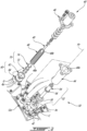
Fig. 2 is an exploded view of a valve of the aircraft engine ofFig. 1 ; -
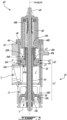
Fig. 3 is a cross-sectional view of the valve ofFig. 2 ; -
Fig. 4 is a partial cross-sectional view of the valve ofFig. 2 according to embodiments; -
Fig. 5 is a perspective, cross-sectional view of a piston assembly of the valve ofFig. 2 according to embodiments; -
Fig. 6 is a partial cross-sectional view of the valve ofFig. 2 according to embodiments; -
Fig. 7 is a planar view of a piston assembly of the valve ofFig. 2 according to embodiments; -
Fig. 8 is a partial cross-sectional view of the piston assembly ofFig. 7 taken along the line 8-8 ofFig. 7 , the piston assembly shown stacked with an axial component of the valve; and -
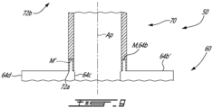
Fig. 9 is a partial cross-sectional view of a piston assembly of the valve ofFig. 2 according to embodiments. -
Fig. 1 illustrates anaircraft engine 10, such as a gas turbine engine, of a type preferably provided for use in subsonic flight, generally comprising in serial flow communication anair intake 11 through which air is drawn, acompressor section 12 within which the air is compressed, acombustor 13 in which the compressed air is mixed with fuel and ignited for generating an annular stream of hot combustion gases, and aturbine section 14 for extracting energy from the combustion gases. - The
aircraft engine 10 ofFig. 1 is a turboprop engine, and therefore includes apower output shaft 15 connected to and driven by one or more of the turbines from theturbine section 14 to transmit a driving force to a propeller of the aircraft via areduction gearbox 17 driving apropeller output flange 16. While anairborne turboprop engine 10 is shown inFig. 1 , it is to be understood that the present disclosure in general, and the switching valve described hereinbelow in particularly, may be equally applied in other types of aircraft engines, including for example turbofan, turboshaft and hybrid engines, and in some cases non-airborne applications. - In the embodiment of
Fig. 1 , theturbine section 14 of theaircraft engine 10 includes two sets of turbines, namely compressor turbine(s) 26 and power turbine(s) 28. The compressor turbine(s) 26 drive the compressor rotors of thecompressor section 12, and are therefore mounted to a common core engine shaft 29. The power turbine(s) 28 are mounted to thepower output shaft 15, which is coaxial and concentric with the core engine shaft 29, which drives thereduction gearbox 17 and ultimately theoutput propeller flange 16. - As can be appreciated from
Fig. 1 , thecompressor section 12 of theaircraft engine 10 is a multi-stage compressor and includes two centrifugal compressors, namely a first, upstream,centrifugal compressor 20 and a second, downstream,centrifugal compressor 22. The upstreamcentrifugal compressor 20 will be referred to herein as the low pressure (LP)compressor 20, and the downstreamcentrifugal compressor 22 will be referred to herein as the high pressure (HP)compressor 22. These twocompressors engine 10 of thecompressor section 12, such that they are in serial flow communication without any intervening compressor stages (e.g. axial compressors) therebetween. A primary airflow occurring in the main flow path of theengine 10 is drawn into theintake 11, directed into theLP compressor 20 for compression, directed into the HPcompressor 22 for further compression, and directed into thecombustor 13 for combustion. - Each of the
compressors compressors LP compressor 20 includes anLP impeller 20a and LP diffuser pipes 20b which receive the compressed air exiting theLP impeller 20a. The HPcompressor 22 includes an HPimpeller 22a and HP diffuser pipes 22b which receive the compressed air exiting the HPimpeller 22a and direct it to thecombustor 13 downstream. Thecompressor section 12 also includes anintercompressor case 12a located axially between theimpellers compressors - Secondary airflows also occur in the
engine 10, and are bled, or taken, from suitable locations of the main flow path in order to provide suitable pressure or cooling to engine components located remotely from the main flow path. For instance, pressurized air may be bled from various sources, for example thelow pressure compressor 20 and/or thehigh pressure compressor 22, to seal bearing cavities, to assist oil scavenging, to cool theengine 10, and to drive aircraft systems such as aircraft pneumatic, air conditioning, and/or de-icing systems, to name a few. Bleed air may be routed to a desired location via flow path(s) defined by suitable pneumatic means including air line(s), passage(s), tube(s) and valve(s) such as anair switching valve 40, referred to henceforth as thevalve 40. In embodiments, thevalve 40 is connected to theintercompressor case 12a, and is adapted to govern whether air provided downstream of thevalve 40 is taken from theLP compressor 20 or the HPcompressor 22. - Referring to
Figs. 2 and3 , thevalve 40 will now be generally described. Thevalve 40 includes a hollowouter housing 42 defining a cylindrical chamber C, or sleeve, about a valve axis Av (also referred to as a chamber axis). Theouter housing 42 defines a first inlet I1 in fluid communication with theHP compressor 22, a second inlet I2 in fluid communication with theLP compressor 20, and an outlet O (Fig. 3 ) respectively in fluid communication with the chamber C. The first inlet I1, the second inlet I2, and the outlet O are openings that are located at an end of the chamber C that may be referred to as an open end. - The
outer housing 42 is in this embodiment integral to theintercompressor case 12a, although theouter housing 42 may be a distinct part assembled to a case or other engine structure in some embodiments. Thevalve 40 may also include aninner housing 44 received by theouter housing 42 so as to line the chamber C. Here, a cylindricalvalve sealing surface 40a of thevalve 40 corresponds to a radially inner surface of theinner housing 44. In some embodiments, theinner housing 44 is omitted, in which case thevalve sealing surface 40a corresponds to a radially inner surface of theouter housing 42. Thevalve sealing surface 40a defines a sealing diameter circumscribing the chamber C. Thevalve 40 also includes ahollow cover 46 connected to the outer housing 42 (in this case via a flange of the inner housing 44) about the valve axis AV so as to define a closed end of the chamber C spaced axially from the open end relative to the valve axis Av. Aspring 48 of thevalve 40 extends along the valve axis Av inside the chamber C and from afirst spring end 48a to an opposite,second spring end 48b lodged inside thecover 46. Ashuttle assembly 50 of thevalve 40 is received in the chamber C and extends along the valve axis Av, engaging thespring 48 at thefirst spring end 48a. Aguide pin 49 of thevalve 40 extends along the valve axis AV between a first pin end held by theouter housing 42 at a bottom of the chamber C and a second pin end held by thecover 46. Thehousing 42, 44 (in this case the inner housing 44) defines anassembly opening 40b of thevalve 40 via which, absent thecover 46, theshuttle assembly 50, thespring 48 and theguide pin 49 are receivable within the chamber C. Theguide pin 49 extends through theshuttle assembly 50 in sliding engagement therewith, rendering theshuttle assembly 50 slidably movable along the valve axis AV inside the chamber C. Theshuttle assembly 50 is movable in the chamber C along the valve axis Av between a first shuttle position and a second shuttle position. In the first shuttle position, theshuttle assembly 50 obstructs the first inlet I1 and fluid communication between the second inlet I2 and the outlet O via the chamber C is open, i.e., unhindered by theshuttle assembly 50. In the second shuttle position, theshuttle assembly 50 obstructs the second inlet I2 and fluid communication between the first inlet I1 and the outlet O via the chamber C is open, i.e., unhindered by theshuttle assembly 50. Theshuttle assembly 50 is operatively connected to thespring 48 to be biased by thespring 48 toward the first shuttle position. - During initial start-up of the
engine 10, air from theHP compressor 22 may be the only pressurized air available, in which case theshuttle assembly 50 is in the first shuttle position.HP compressor 22 air flows, for example via a transfer tube, through thehousing 42 and into the chamber C via the first inlet I1. From the chamber C, the air exits via the outlet O, passes through a cavity in theintercompressor case 12a, to be supplied to its destination via suitable external lines. As theLP compressor 20 pressure increases (NH < 40-45%), it overcomes the biasing force of thespring 48 to move theshuttle assembly 50 to the second shuttle position, thereby interrupting the flow ofHP compressor 22 air via the outlet O and replacing it with a flow ofLP compressor 20 air. Generally stated, thevalve 40 acts as a switch between air sources (hence the expression "switching valve") governing from which source the air is to be bled depending on the operation regime of theengine 10. - Referring to
Fig. 3 , theshuttle assembly 50 includes ashuttle 52 having astem 54 extending longitudinally along a stem axis AS from afirst stem end 54a to asecond stem end 54b. Theshuttle 52 also has aflange 56 projecting radially outwardly from thestem 54 at a first axial location S1 of thestem 54 between the first and second stem ends 54a, 54b. At a second axial location S2 of thestem 54 proximate to thesecond stem end 54b, theshuttle 52 has an axial landmark defined by thestem 54. The first and second axial locations S1, S2 of thestem 54 represent opposite boundaries of an axial volume inside whichstackable components shuttle assembly 50 are to be stacked during assembly of thevalve 40. As will be explained hereinbelow, during the assembly of thevalve 40, the axial landmark of theshuttle 52 may be indicative of whether one or more of thestackable components shuttle 52 also has a blockingfeature 58 located proximate to thefirst stem end 54a and spaced axially relative to theflange 56. The blockingfeature 58 is shaped complementarily to an inner wall of thevalve 40 defining the chamber C to cooperate therewith such that fluid communication between the first inlet I1 or the second inlet I2 and the chamber C is blocked depending on the position of theshuttle assembly 50. In the depicted embodiment, the blockingfeature 58 has a flange-like shape projecting radially outwardly from thestem 54, having afirst sealing surface 58a, for example an axial surface, for sealing the first inlet I1, and asecond sealing surface 58b, for example an axial surface, for sealing the second inlet I2. - Among the
stackable components shuttle assembly 50 includes apiston assembly 60 extending about a piston axis AP. Thepiston assembly 60 is received within the chamber C such that the piston axis AP and the valve axis AV are collinear. During assembly of thevalve 40, thepiston assembly 60 stacks onto theflange 56 and thespring 48 subsequently stacks onto thepiston assembly 60. Thepiston assembly 60 has opposite axial sides, namely a high-pressure side 60a laid against theflange 56 and a low-pressure side 60b laid against thespring 48. Theshuttle assembly 50 thus engages thespring 48 via the low-pressure side 60b of thepiston assembly 60. - Referring to
Figs. 4 and5 , thepiston assembly 60 generally includes a sealingring 62 and a disc-like piston body 64 surrounded by the sealingring 62. As will be described hereinbelow, thepiston body 64 defines an annular groove G into which the sealingring 62 is lodged to be axially constrained, or held. The sealingring 62 includes opposite first and second axial ring surfaces 62a, 62b, and radially inner and outer ring surfaces 62c, 62d extending axially therebetween. As best seen inFig. 2 , the sealingring 62 is of the split ring type, which may facilitate radial contraction and/or expansion of the sealingring 62. In the depicted embodiments, the sealingring 62 has ends that are circumferentially spaced from one another and that have cross sections similar to a remainder of the sealingring 62, defining a gap via which the sealingring 62 may be traversed radially and axially. In other embodiments, the ends may instead define one or more tabs that overlap one another, defining a chicane, or non-linear path, in the axial direction from the first axial ring surface 62a to the second axial ring surface 62b. It is contemplated however that in some embodiments, the sealingring 62 could be closed, i.e., uninterrupted. The sealingring 62 may be constructed of a variety of suitable materials suitable for achieving its sealing function, including one or more of metal, carbon, etc. - The
piston body 64 has opposite first and secondaxial piston surfaces outer piston surfaces inner piston surface 64c may also be referred to as a piston bore having an inner piston diameter of thepiston body 64. The radiallyouter piston surface 64d has an outer piston diameter of thepiston body 64 that is greater than the inner piston diameter yet smaller than the sealing diameter. As mentioned above, thepiston body 64 defines an annular groove G, which extends radially inwardly from the radiallyouter piston surface 64d. The annular groove G (hereinafter the groove G) is sized for receiving the sealingring 62. Indeed, the sealingring 62 extends radially inwardly relative to the piston axis AP from outside the groove G (i.e., outward of the outer piston diameter) to inside the groove G (i.e., inward of the outer piston diameter). The groove G has first and second groove walls Ga, Gb facing one another, and a groove bottom Gc extending axially between the first and second groove walls Ga, Gb (Fig. 4 ). In embodiments, the groove G is sized such that a radial gap is formed between the groove bottom Gc and the radially inner ring surface 62c. This radial gap may allow radial contraction of the sealingring 62 unhindered by thepiston body 64. For example, the sealingring 62 may have an outer diameter that is greater than the sealing diameter of the chamber C and, in order to fit the sealingring 62 into the chamber C, the sealingring 62 may be radially contracted, bringing the radially inner ring surface 62c closer to the groove bottom Gc. Such radial contraction may be facilitated by the split configuration of the sealingring 62. Moreover, such radial contraction may advantageously bias the radially outer ring surface 62d against thevalve sealing surface 40a. When thepiston assembly 60 is received inside the chamber C, the radially outer ring surface 62d is in radial engagement with thevalve sealing surface 40a, thereby forming an axial seal partitioning the chamber C into high-pressure and low-pressure portions on either side of the sealingring 62. - A height of the groove G (i.e., a distance between the first and second groove walls Ga, Gb) may generally correspond to a height of the sealing ring 62 (i.e., a distance between the first and second axial ring surfaces 62a, 62b). In embodiments, the groove G is sized such that the sealing
ring 62 is axially loose relative to the piston body 64 (i.e., the height of the sealingring 62 is less than that of the groove G). However, in such cases, as pressure is greater on the high-pressure side 60a than on the low-pressure side 60b of the piston assembly 60 (and hence of the sealing ring 62), the second axial ring surface 62b is biased against the second axial wall Gb of the groove G, thereby forming a radial seal preventing, or at least hindering, circumvention of the axial seal by fluid circulating in the chamber C. - Among the
stackable components shuttle assembly 50 includes at least oneaxial component 70 disposed about the piston axis AP spaced from theflange 56 by thepiston assembly 60 relative to the piston axis AP. Suchaxial component 70 may be used to space thepiston assembly 60 from thesecond stem end 54b relative to the stem axis AS, for example to hold thepiston assembly 60 against theflange 56. Hence, during assembly of thevalve 40, suchaxial component 70 is installed onto theshuttle 52 subsequently to the stacking of thepiston assembly 60 onto theflange 56 of theshuttle 52, and ideally prior to the stacking of thespring 48 onto thepiston assembly 60. The at least oneaxial component 70 may for example include a tubular sleeve 72 (hereinafter the sleeve 72). Thesleeve 72 extends longitudinally along a sleeve axis (not shown) from afirst sleeve end 72a to asecond sleeve end 72b opposite to thefirst sleeve end 72a. Thefirst sleeve end 72a matingly engages the low-pressure side 60b of thepiston assembly 60 upon stacking thereon with the sleeve axis being collinear with the piston axis AP, as will be described hereinbelow. It is contemplated that thesleeve 72 may include a plurality of sleeve portions, for example a first sleeve portion having thefirst sleeve end 72a and a second sleeve portion having thesecond sleeve end 72b. Axial movement of thesleeve 72 relative to the stem axis AS is bound at thefirst sleeve end 72a by thepiston assembly 60, and at thesecond sleeve end 72b for example by anotheraxial component 70 such as afastener 74, among other possibilities. Thefastener 74, also referred to as ashuttle fastener 74, may be a retaining ring, as shown lodged in anannular groove 54c of the stem 54 (hereinafter thestem groove 54c) defining the second axial location S2. In some embodiments, thefastener 74 may instead be a nut threadedly engaged with thestem 54 at thesecond stem end 54b. Theshuttle fastener 74 is engageable with theshuttle 52 at the axial landmark to secure thesleeve 72 onto theshuttle 52 between theflange 56 and theshuttle fastener 74. In the depicted embodiment, thestem groove 54c corresponds to the axial landmark of theshuttle 52. The second axial location S2 of thestem 54 is spaced away from thesecond stem end 54b, although it is contemplated that in other embodiments, the second axial location S2, and hence the axial landmark of theshuttle 52, may be defined by thesecond stem end 54b. - With reference to
Figs. 4 to 8 , details pertaining to the assembly of thevalve 40 will now be provided. Thepiston assembly 60 may be said directional as it has an axial side, namely the high-pressure side 60a, which presents features that are suited for facing toward the high-pressure side of thevalve 40, i.e., toward theflange 56 and the inlets I1, I2 of thevalve 40. Conversely, the low-pressure side 60b may lack such features and/or present features that are ill-suited for facing toward the high-pressure side of thevalve 40. For example, the high-pressure side 60a may present a suitableouter transition surface 64e extending from the firstaxial piston surface 64a to the radiallyouter piston surface 64d, such as a bevel (as shown) or a radius. Thisouter transition surface 64e may for instance serve alignment purposes, as it may lead thepiston assembly 60 radially inward of the access opening 40b as thepiston assembly 60 is installed into the chamber C. The high-pressure side 60a may also present aninner transition surface 64f extending from the firstaxial piston surface 64a to the radiallyinner piston surface 64c, such as a bevel (as shown), a radius or another suitable surface defining a recess, or clearance, extending radially outwardly from the inner piston diameter. Thisinner transition surface 64f may be sized for receiving a radius at the junction between thestem 54 and theflange 56, allowing the seating of the firstaxial piston surface 64a onto theflange 56 as thepiston assembly 60 is stacked onto theshuttle 52. In embodiments, theinner transition surface 64f may be referred to as afirst recess 64f of thepiston body 64 defined axially inwardly from the firstaxial piston surface 64a. The high-pressure side 60a may also present adiscontinuity 64g in the firstaxial piston surface 64a, for example a junction between first and second components of thepiston body 64 having been assembled together. Thediscontinuity 64g may be at a radial location relative to the stem axis AS between the inner piston diameter and an outer flange diameter circumscribing theflange 56. Thisdiscontinuity 64g may advantageously be laid onto theflange 56, which may shield thediscontinuity 64g from the high-pressure environment occurring thevalve 40 and thus assist in preventing unwanted disassembly of thepiston body 64. - In accordance with the present technology, to limit occurrences of misorientation of the
piston assembly 60 inside the chamber C during assembly of thevalve 40, thepiston assembly 60 is structured to abut theaxial component 70 when the latter is stacked thereon in collinear alignment therewith so as to define different heights depending on whichside piston assembly 60 lays against theflange 56 and, conversely, whichside axial component 70. Thestackable components pressure side 60b with the high-pressure side 60a engaging theflange 56, and a second stacking height greater than the first stacking height when the secondaxial piston surface 64b engages the high-pressure side 60a with the low-pressure side 60b engaging theflange 56. A difference between the first and second stacking heights is a result of thepiston body 64 being suitably sized, on eitherside first sleeve end 72a. In either case, as thestackable components flange 56 to proximate the access opening 40b of thevalve 40, a worker inspecting thestem assembly 50 via the access opening 40b may readily verify whether the height defined by thestackable components second sleeve end 72b relative to the axial landmark. In some embodiments, the first stacking height extends from the first axial location S1 of thestem 54 to proximate (albeit short of) the second axial location S2 of the stem 54 (for example as shown by the location of thesecond sleeve end 72b inFig. 4 ), whereas the second stacking height extends from the first axial location S1 to at least the second axial location S2 (for example as schematically shown at 72b' inFig. 4 ). In some such embodiments, thestackable components valve 40 as installation of thefastener 74 at the second axial location S2 is hindered by theaxial component 70, for example thesleeve 72 axially overlaying thestem groove 54c. - Referring to
Figs. 4 and5 , on the low-pressure side 60b, thepiston body 64 has a mating connector M defined by the secondaxial piston surface 64b and located radially outward of the piston bore, onto which theaxial component 70 may be stacked. A shape of the mating connector M is complementary to that of thefirst sleeve end 72a, such that thefirst sleeve end 72a is matingly engageable with the mating connector M past the secondaxial piston surface 64b up to a certain engagement depth, or second distance, upon thesleeve 72 being stacked onto thepiston body 64 on the low-pressure side 60b. In some embodiments, the second distance corresponds to the difference between the first and second stacking heights. In the depicted embodiment, the mating connector M is provided in the form of a recess extending axially inwardly from the secondaxial piston surface 64b relative to the piston axis AP. The recess may also be adjacent to the piston bore (as shown) or spaced radially outwardly therefrom relative to the piston axis AP. The recess (which may also be referred to as a second recess of thepiston body 64, for example when thefirst recess 64f is present) is circumscribed radially outwardly relative to the piston axis AP by an outer recess diameter greater than the inner piston diameter. For embodiments in which the mating connector M is the recess, thefirst sleeve end 72a may thus be sized to be receivable within the recess, and the recess may be said to be sized to receive thefirst sleeve end 72a. As shown in the depicted embodiment, the recess may be annular in shape, although other shapes are contemplated. - On the high-
pressure side 60a, thepiston body 64 may be substantially flat, having for example the firstaxial piston surface 64a extending radially between the outer andinner transition surfaces first sleeve end 72a may engage with a flat portion of thepiston body 64 corresponding to the firstaxial piston surface 64a or to another surface of thepiston body 64 coplanar with the firstaxial piston surface 64a. In the depicted embodiment, an outermost diameter of thesleeve 72 at thefirst sleeve end 72a corresponds to at least an outermost diameter of theinner transition surface 64f defined by the firstaxial piston surface 64a. Nevertheless, in some embodiments, the high-pressure side 60a may present features allowing thefirst sleeve end 72a to matingly engage therewith past the firstaxial piston surface 64a up to a certain engagement depth, or first distance. However, thepiston body 64 and thesleeve 72 are structured and arranged relative to one another such that should there be any mating engagement possible between thepiston body 64 and thefirst sleeve end 72a on the high-pressure side 60a, the second distance is greater than the first distance, i.e., a mating engagement of thefirst sleeve end 72a via the low-pressure side 60b of thepiston assembly 60 is greater than any mating engagement of thefirst sleeve end 72a via the high-pressure side 60a. Stated otherwise, thefirst sleeve end 72a is axially stackable on thepiston body 64 via the firstaxial piston surface 64a to define the first distance between thefirst sleeve end 72a and the firstaxial piston surface 64a, and via the secondaxial piston surface 64b to define the second distance between thefirst sleeve end 72a and the secondaxial piston surface 64b. The second distance is greater than the first distance. The first distance may be null. - Turning now to
Fig. 6 , thestackable components stackable components first sleeve end 72a may have complementary non-annular shapes F1, F1' defining antirotational features cooperable to hinder rotation of thepiston body 64 and thesleeve 72 relative to one another about the valve axis Av. In one contemplated implementation, the mating connector M has an annular portion and a keyway F1 extending radially outwardly from the annular portion relative to the piston axis AP. Conversely, thefirst sleeve end 72a has an annular portion and a key-like protrusion F1' projecting radially outwardly from the annular portion relative to the sleeve axis. In embodiments, thepiston body 64 and thesleeve 72 respectively define a first keyway F2 and a second keyway F2' arranged to be in register with one another upon thefirst sleeve end 72a being stacked onto the low-pressure side 60b in a suitable orientation about the piston axis AP. The first keyway F2 may be in communication with the mating component M. The second keyway F2' is located proximate to thefirst sleeve end 72a. Asleeve fastener 76, in this case a pin, may extend from inside the first keyway F2 to inside the second keyway F2'. Thesleeve fastener 76, by being so engaged with both thepiston body 64 and thesleeve 72, hinders axial movement of thepiston body 64 and thesleeve 72 relative to one another along the valve axis Av. In embodiments, thefirst sleeve end 72a and the mating connector M are respectively threaded and tapped (or vice versa) complementarily so that they may be threadedly engaged with one another. - Referring to
Figs. 7 and 8 , another exemplary embodiment of thevalve 40 will now be described. In this embodiment, the mating component M is provided in the form of a crenelated ridge extending circumferentially around the piston axis AP radially outward of the piston bore. The mating component M includes a plurality of axial projections that are circumferentially spaced from one another and that extend axially from anaxial surface 64b' that is recessed relative to the secondaxial piston surface 64b to their respective ends which define the secondaxial piston surface 64b. In some embodiments, the projections may extend by different heights, in which case an end of a tallest one of the projections defines the secondaxial piston surface 64b. Thefirst sleeve end 72a has a crenelated shape M' complementary to that of the mating component M. - Referring to
Fig. 9 , yet another exemplary embodiment of thevalve 40 will now be described. In this embodiment, the mating component M is provided in the form of an annular ridge extending circumferentially around the piston axis AP radially outward of the piston bore. The mating component M extends axially from anaxial surface 64b' that is recessed relative to the secondaxial piston surface 64b to an end which defines the secondaxial piston surface 64b. Thefirst sleeve end 72a has a shape M' complementary to that of the mating component M, in this case an annular groove extending circumferentially around the sleeve axis and axially from thefirst sleeve end 72a toward thesecond sleeve end 72b. - The embodiments described in this document provide non-limiting examples of possible implementations of the present technology. Upon review of the present disclosure, a person of ordinary skill in the art will recognize that changes may be made to the embodiments described herein without departing from the scope of the present technology. For example, embodiments of the present technology have been described hereinabove as implemented in an aircraft engine switching valve having a housing integral with an intercompressor case of the aircraft engine. It is contemplated however that the present technology may be implemented in other types of valve. Yet further modifications could be implemented by a person of ordinary skill in the art in view of the present disclosure, which modifications would be within the scope of the present technology.
Claims (15)
- A valve (40) for an air system in an aircraft engine (10), comprising:a piston housing (42) defining a cylindrical chamber (C) having a valve axis (Av);a piston body (64) received within the chamber (C), the piston body (64) extending annularly about a piston axis (AP) collinear with the valve axis (AV), the piston body (64) extending axially from a first axial piston surface (64a) to a second axial piston surface (64b) axially spaced apart from the first axial piston surface (64a), the piston body (64) defining a piston bore (64c) extending axially from the first axial piston surface (64a) to the second axial piston surface (64b) along the piston axis (AP), the piston body (64) having a mating connector (M) defined by the second axial piston surface (64b) and located radially outward of the piston bore (64c) relative to the piston axis (AP); anda sleeve (72) extending longitudinally from a first sleeve end (72a) matingly engaged with the mating connector (M) of the piston body (64) to a second sleeve end (72b) along a sleeve axis collinear with the valve axis (AV), the first sleeve end (72a) axially stacked on the piston body (64) via the first axial piston surface (64a) to define a first distance between the first sleeve end (72a) and the first axial piston surface (64a), and via the second axial piston surface (64b) to define a second distance between the first sleeve end (72a) and the second axial piston surface (64b), the second distance greater than the first distance.
- The valve (40) of claim 1, further comprising a shuttle (52) having a stem (54) extending longitudinally along a stem axis (As) collinear with the valve axis (Av), the shuttle (52) having a flange (56) projecting radially outwardly from the stem (54) relative to the valve axis (AV) at a first axial location (S1) of the stem (54), the stem (54) defining an axial landmark (54c) of the shuttle (52) at a second axial location (S2) of the stem (54), the piston body (64) and the sleeve (72) axially stacked onto the flange (56) such that the first axial piston surface (64a) lays against the flange (56), the first sleeve end (72a) is matingly engaged with the mating connector (M) and the second sleeve end (72b) is located between the second axial piston surface (64b) and the axial landmark (54c) proximate to the axial landmark (54c).
- The valve (40) of claim 2, further comprising a shuttle fastener (74) engageable with the shuttle (52) at the axial landmark (54c) to secure the sleeve (72) between the flange (56) and the shuttle fastener (74).
- The valve (40) of claim 2 or 3, wherein the axial landmark (54c) is an annular groove (54c) extending circumferentially around the stem axis (AS).
- The valve (40) of claim 2, 3 or 4, wherein upon the piston body (64) and the sleeve (72) being stacked onto the flange (56) such that the second axial piston surface (64b) lays against the flange (56) and the first sleeve end (72a) lays against the piston body (64), the sleeve (72) extends from the piston body (64) to at least the axial landmark (54c).
- The valve (40) of any preceding claim, wherein the mating connector (M) and the first sleeve end (72a) respectively define complementary anti-rotational features that cooperate to hinder rotation of the piston body (64) and the sleeve (72) relative to one another about the valve axis (AV).
- The valve (40) of any preceding claim, further comprising a sleeve fastener (76) engaged with the piston body (64) and the sleeve (72) to hinder axial movement of the piston body (64) and the sleeve (72) relative to one another along the valve axis (AV).
- The valve (40) of any preceding claim, wherein the mating connector (M) is a recess extending axially inwardly relative to the second axial piston surface (64b).
- The valve (40) of claim 8, wherein the recess is annular in shape.
- The valve (40) of any of claims 1 to 7, wherein the mating connector (M) includes at least one axial projection, the first sleeve end (72a) defining a shape complementary to that of the at least one axial projection.
- An aircraft engine (10) comprising:a compressor (12) including an intercompressor case (12a); andthe valve (40) of any of claims 2 to 5, wherein the intercompressor case (12a) defines the piston housing (42) of the valve (40).
- The aircraft engine (10) of claim 11, wherein the mating connector (M) and the first sleeve end (72a) respectively define complementary anti-rotational features that cooperate to hinder rotation of the piston body (64) and the sleeve (72) relative to one another about the valve axis (Av).
- The aircraft engine (10) of claim 11 or 12, wherein the mating connector (M) is a recess extending axially inwardly relative to the second axial piston surface (64b), and the piston body (64) and the sleeve (72) respectively define a first keyway (F2) in communication with the recess and a second keyway (F2') proximate to the first sleeve end (72a), the first sleeve end (72a) being received within the recess, the first keyway (F2) and the second keyway (F2') being in register and the sleeve fastener (76) extending from inside the first keyway (F2) to inside the second keyway (F2').
- The aircraft engine (10) of any of claims 11 to 13, wherein a junction between the first axial piston surface (64a) and the piston bore (64c) is a first recess (64f) of the piston body (64) defined axially inwardly from the first axial piston surface (64a), and the mating connector (M) is a second recess extending axially inwardly relative to the second axial piston surface (64b), the piston body (64) and the sleeve (72) sized relative to one another such that the first sleeve end (72a) is receivable axially within the second recess by a depth greater than within the first recess (64f).
- The aircraft engine (10) of any of claims 11 to 14, wherein the mating connector (M) and the first sleeve end (72a) have complementary crenelated shapes.
Applications Claiming Priority (1)
| Application Number | Priority Date | Filing Date | Title |
|---|---|---|---|
| US17/805,046 US11939874B2 (en) | 2022-06-02 | 2022-06-02 | Switching valve |
Publications (1)
| Publication Number | Publication Date |
|---|---|
| EP4286713A1 true EP4286713A1 (en) | 2023-12-06 |
Family
ID=86693124
Family Applications (1)
| Application Number | Title | Priority Date | Filing Date |
|---|---|---|---|
| EP23175852.5A Pending EP4286713A1 (en) | 2022-06-02 | 2023-05-26 | Switching valve |
Country Status (3)
| Country | Link |
|---|---|
| US (1) | US11939874B2 (en) |
| EP (1) | EP4286713A1 (en) |
| CA (1) | CA3198418A1 (en) |
Citations (2)
| Publication number | Priority date | Publication date | Assignee | Title |
|---|---|---|---|---|
| US4470428A (en) * | 1982-05-21 | 1984-09-11 | Eaton Corporation | Unloader and check valve |
| EP3255282A1 (en) * | 2016-06-09 | 2017-12-13 | Hamilton Sundstrand Corporation | Bleed valve with altitude compensating pneumatic actuator |
Family Cites Families (16)
| Publication number | Priority date | Publication date | Assignee | Title |
|---|---|---|---|---|
| US2931673A (en) | 1955-11-25 | 1960-04-05 | John T Gondek | Pressure seal |
| US4830331A (en) | 1988-07-22 | 1989-05-16 | Vindum Jorgen O | High pressure fluid valve |
| US4941502A (en) | 1989-05-31 | 1990-07-17 | Keystone International Holdings Corp. | Low pressure recirculation valve |
| US6122905A (en) * | 1998-02-13 | 2000-09-26 | Pratt & Whitney Canada Corp. | Compressor bleed valve |
| US6698446B2 (en) | 2002-07-12 | 2004-03-02 | R. Conrader Company | Check valve |
| DE102006028638A1 (en) | 2006-06-22 | 2008-01-03 | Robert Bosch Gmbh | piston pump |
| DE102008005088B3 (en) | 2008-01-18 | 2009-07-30 | A. Kayser Automotive Systems Gmbh | Valve with a resiliently movable or elastically and / or flexibly deformable sealing element |
| US20100092116A1 (en) * | 2008-10-15 | 2010-04-15 | Honeywell International Inc. | Pressure balanced valve assembly and aircraft buffer cooler system employing the same |
| US10125789B2 (en) * | 2013-02-15 | 2018-11-13 | United Technologies Corporation | Bushing arranged between a body and a shaft, and connected to the body |
| ITMI20131609A1 (en) * | 2013-09-30 | 2015-03-31 | Fpt Ind Spa | PROTECTION SYSTEM OF A TURBOCHARGER SYSTEM, IN PARTICULAR FOR THE PREVENTION OF A RELATIVE DAMAGE WHEN A PRESSURE OF A RELATIVE LUBRICATION OIL IS INSUFFICIENT |
| US9698579B2 (en) * | 2014-10-24 | 2017-07-04 | General Electric Company | Method for routing wire bundles from a rotor shaft of a turbomachine |
| US9689315B2 (en) * | 2015-02-13 | 2017-06-27 | Hamilton Sundstrand Corporation | Full-area bleed valves |
| US10001060B2 (en) | 2015-06-18 | 2018-06-19 | Pratt & Whitney Canada Corp. | Valve assembly with oil shut-off valve |
| US10801509B2 (en) | 2018-07-26 | 2020-10-13 | Honeywell International Inc. | Bleed air selector valve |
| US10883616B2 (en) | 2019-02-06 | 2021-01-05 | ECO Holding 1 GmbH | Control valve for cam phaser and method for mounting the control valve |
| IT201900012855A1 (en) | 2019-07-25 | 2021-01-25 | Dab Pumps Spa | DEVICE FOR THE PROTECTION FROM OVERPRESSURE OF AN ELECTRIC PUMP |
-
2022
- 2022-06-02 US US17/805,046 patent/US11939874B2/en active Active
-
2023
- 2023-05-02 CA CA3198418A patent/CA3198418A1/en active Pending
- 2023-05-26 EP EP23175852.5A patent/EP4286713A1/en active Pending
Patent Citations (2)
| Publication number | Priority date | Publication date | Assignee | Title |
|---|---|---|---|---|
| US4470428A (en) * | 1982-05-21 | 1984-09-11 | Eaton Corporation | Unloader and check valve |
| EP3255282A1 (en) * | 2016-06-09 | 2017-12-13 | Hamilton Sundstrand Corporation | Bleed valve with altitude compensating pneumatic actuator |
Also Published As
| Publication number | Publication date |
|---|---|
| US11939874B2 (en) | 2024-03-26 |
| US20230392512A1 (en) | 2023-12-07 |
| CA3198418A1 (en) | 2023-12-02 |
Similar Documents
| Publication | Publication Date | Title |
|---|---|---|
| US10196975B2 (en) | Turboprop engine with compressor turbine shroud | |
| US6418727B1 (en) | Combustor seal assembly | |
| US6347508B1 (en) | Combustor liner support and seal assembly | |
| EP1947298B1 (en) | Slider seal assembly for gas turbine engine | |
| US8177495B2 (en) | Method and apparatus for turbine interstage seal ring | |
| US20180209651A1 (en) | Combustor with axially staged fuel injector assembly | |
| CN115434814A (en) | Turbine engine with rotor seal assembly | |
| US11939874B2 (en) | Switching valve | |
| US9243802B2 (en) | Two-stage combustor for gas turbine engine | |
| US9027350B2 (en) | Gas turbine engine having dome panel assembly with bifurcated swirler flow | |
| US8276390B2 (en) | Method and system for providing a splitter to improve the recovery of compressor discharge casing | |
| EP4524470A1 (en) | Gas turbine engine and fuel nozzle therefor | |
| US11725532B1 (en) | Switching valve | |
| US20250035039A1 (en) | System for cooling oil in an aircraft turbine engine | |
| US10502077B2 (en) | Vane retainer | |
| EP3699400B1 (en) | Gas turbine engine system with light weight low blockage slider seal | |
| US10519869B2 (en) | Electrical and mechanical connections through firewall | |
| US11306593B2 (en) | Key washer for a gas turbine engine | |
| US12607266B2 (en) | Double bellows valve for preventing undesired valve failure positions | |
| US20180306367A1 (en) | Slip Joint Assembly | |
| US20200102886A1 (en) | Customer bleed air pressure loss reduction |
Legal Events
| Date | Code | Title | Description |
|---|---|---|---|
| PUAI | Public reference made under article 153(3) epc to a published international application that has entered the european phase |
Free format text: ORIGINAL CODE: 0009012 |
|
| STAA | Information on the status of an ep patent application or granted ep patent |
Free format text: STATUS: THE APPLICATION HAS BEEN PUBLISHED |
|
| AK | Designated contracting states |
Kind code of ref document: A1 Designated state(s): AL AT BE BG CH CY CZ DE DK EE ES FI FR GB GR HR HU IE IS IT LI LT LU LV MC ME MK MT NL NO PL PT RO RS SE SI SK SM TR |
|
| STAA | Information on the status of an ep patent application or granted ep patent |
Free format text: STATUS: REQUEST FOR EXAMINATION WAS MADE |
|
| 17P | Request for examination filed |
Effective date: 20240606 |
|
| RBV | Designated contracting states (corrected) |
Designated state(s): AL AT BE BG CH CY CZ DE DK EE ES FI FR GB GR HR HU IE IS IT LI LT LU LV MC ME MK MT NL NO PL PT RO RS SE SI SK SM TR |