EP4286679A1 - Modular fuel transfer pump flow passage structure and fuel transfer pump - Google Patents
Modular fuel transfer pump flow passage structure and fuel transfer pump Download PDFInfo
- Publication number
- EP4286679A1 EP4286679A1 EP23176356.6A EP23176356A EP4286679A1 EP 4286679 A1 EP4286679 A1 EP 4286679A1 EP 23176356 A EP23176356 A EP 23176356A EP 4286679 A1 EP4286679 A1 EP 4286679A1
- Authority
- EP
- European Patent Office
- Prior art keywords
- bellows
- adapter
- fuel transfer
- motor
- transfer pump
- Prior art date
- Legal status (The legal status is an assumption and is not a legal conclusion. Google has not performed a legal analysis and makes no representation as to the accuracy of the status listed.)
- Granted
Links
Images



Classifications
-
- F—MECHANICAL ENGINEERING; LIGHTING; HEATING; WEAPONS; BLASTING
- F04—POSITIVE - DISPLACEMENT MACHINES FOR LIQUIDS; PUMPS FOR LIQUIDS OR ELASTIC FLUIDS
- F04D—NON-POSITIVE-DISPLACEMENT PUMPS
- F04D3/00—Axial-flow pumps
- F04D3/005—Axial-flow pumps with a conventional single stage rotor
-
- F—MECHANICAL ENGINEERING; LIGHTING; HEATING; WEAPONS; BLASTING
- F02—COMBUSTION ENGINES; HOT-GAS OR COMBUSTION-PRODUCT ENGINE PLANTS
- F02M—SUPPLYING COMBUSTION ENGINES IN GENERAL WITH COMBUSTIBLE MIXTURES OR CONSTITUENTS THEREOF
- F02M37/00—Apparatus or systems for feeding liquid fuel from storage containers to carburettors or fuel-injection apparatus; Arrangements for purifying liquid fuel specially adapted for, or arranged on, internal-combustion engines
- F02M37/04—Feeding by means of driven pumps
- F02M37/08—Feeding by means of driven pumps electrically driven
-
- F—MECHANICAL ENGINEERING; LIGHTING; HEATING; WEAPONS; BLASTING
- F04—POSITIVE - DISPLACEMENT MACHINES FOR LIQUIDS; PUMPS FOR LIQUIDS OR ELASTIC FLUIDS
- F04B—POSITIVE-DISPLACEMENT MACHINES FOR LIQUIDS; PUMPS
- F04B17/00—Pumps characterised by combination with, or adaptation to, specific driving engines or motors
- F04B17/06—Mobile combinations
-
- F—MECHANICAL ENGINEERING; LIGHTING; HEATING; WEAPONS; BLASTING
- F04—POSITIVE - DISPLACEMENT MACHINES FOR LIQUIDS; PUMPS FOR LIQUIDS OR ELASTIC FLUIDS
- F04B—POSITIVE-DISPLACEMENT MACHINES FOR LIQUIDS; PUMPS
- F04B53/00—Component parts, details or accessories not provided for in, or of interest apart from, groups F04B1/00 - F04B23/00 or F04B39/00 - F04B47/00
- F04B53/16—Casings; Cylinders; Cylinder liners or heads; Fluid connections
-
- F—MECHANICAL ENGINEERING; LIGHTING; HEATING; WEAPONS; BLASTING
- F04—POSITIVE - DISPLACEMENT MACHINES FOR LIQUIDS; PUMPS FOR LIQUIDS OR ELASTIC FLUIDS
- F04B—POSITIVE-DISPLACEMENT MACHINES FOR LIQUIDS; PUMPS
- F04B53/00—Component parts, details or accessories not provided for in, or of interest apart from, groups F04B1/00 - F04B23/00 or F04B39/00 - F04B47/00
- F04B53/22—Arrangements for enabling ready assembly or disassembly
-
- F—MECHANICAL ENGINEERING; LIGHTING; HEATING; WEAPONS; BLASTING
- F04—POSITIVE - DISPLACEMENT MACHINES FOR LIQUIDS; PUMPS FOR LIQUIDS OR ELASTIC FLUIDS
- F04D—NON-POSITIVE-DISPLACEMENT PUMPS
- F04D13/00—Pumping installations or systems
- F04D13/02—Units comprising pumps and their driving means
- F04D13/06—Units comprising pumps and their driving means the pump being electrically driven
- F04D13/068—Battery powered
-
- F—MECHANICAL ENGINEERING; LIGHTING; HEATING; WEAPONS; BLASTING
- F04—POSITIVE - DISPLACEMENT MACHINES FOR LIQUIDS; PUMPS FOR LIQUIDS OR ELASTIC FLUIDS
- F04D—NON-POSITIVE-DISPLACEMENT PUMPS
- F04D13/00—Pumping installations or systems
- F04D13/02—Units comprising pumps and their driving means
- F04D13/06—Units comprising pumps and their driving means the pump being electrically driven
- F04D13/0693—Details or arrangements of the wiring
-
- F—MECHANICAL ENGINEERING; LIGHTING; HEATING; WEAPONS; BLASTING
- F04—POSITIVE - DISPLACEMENT MACHINES FOR LIQUIDS; PUMPS FOR LIQUIDS OR ELASTIC FLUIDS
- F04D—NON-POSITIVE-DISPLACEMENT PUMPS
- F04D13/00—Pumping installations or systems
- F04D13/02—Units comprising pumps and their driving means
- F04D13/06—Units comprising pumps and their driving means the pump being electrically driven
- F04D13/08—Units comprising pumps and their driving means the pump being electrically driven for submerged use
- F04D13/086—Units comprising pumps and their driving means the pump being electrically driven for submerged use the pump and drive motor are both submerged
-
- F—MECHANICAL ENGINEERING; LIGHTING; HEATING; WEAPONS; BLASTING
- F04—POSITIVE - DISPLACEMENT MACHINES FOR LIQUIDS; PUMPS FOR LIQUIDS OR ELASTIC FLUIDS
- F04D—NON-POSITIVE-DISPLACEMENT PUMPS
- F04D29/00—Details, component parts, or accessories
- F04D29/08—Sealings
- F04D29/086—Sealings especially adapted for liquid pumps
-
- F—MECHANICAL ENGINEERING; LIGHTING; HEATING; WEAPONS; BLASTING
- F04—POSITIVE - DISPLACEMENT MACHINES FOR LIQUIDS; PUMPS FOR LIQUIDS OR ELASTIC FLUIDS
- F04D—NON-POSITIVE-DISPLACEMENT PUMPS
- F04D29/00—Details, component parts, or accessories
- F04D29/40—Casings; Connections of working fluid
- F04D29/42—Casings; Connections of working fluid for radial or helico-centrifugal pumps
- F04D29/426—Casings; Connections of working fluid for radial or helico-centrifugal pumps especially adapted for liquid pumps
-
- F—MECHANICAL ENGINEERING; LIGHTING; HEATING; WEAPONS; BLASTING
- F04—POSITIVE - DISPLACEMENT MACHINES FOR LIQUIDS; PUMPS FOR LIQUIDS OR ELASTIC FLUIDS
- F04D—NON-POSITIVE-DISPLACEMENT PUMPS
- F04D3/00—Axial-flow pumps
-
- F—MECHANICAL ENGINEERING; LIGHTING; HEATING; WEAPONS; BLASTING
- F04—POSITIVE - DISPLACEMENT MACHINES FOR LIQUIDS; PUMPS FOR LIQUIDS OR ELASTIC FLUIDS
- F04D—NON-POSITIVE-DISPLACEMENT PUMPS
- F04D9/00—Priming; Preventing vapour lock
- F04D9/007—Preventing loss of prime, siphon breakers
-
- F—MECHANICAL ENGINEERING; LIGHTING; HEATING; WEAPONS; BLASTING
- F16—ENGINEERING ELEMENTS AND UNITS; GENERAL MEASURES FOR PRODUCING AND MAINTAINING EFFECTIVE FUNCTIONING OF MACHINES OR INSTALLATIONS; THERMAL INSULATION IN GENERAL
- F16L—PIPES; JOINTS OR FITTINGS FOR PIPES; SUPPORTS FOR PIPES, CABLES OR PROTECTIVE TUBING; MEANS FOR THERMAL INSULATION IN GENERAL
- F16L27/00—Adjustable joints; Joints allowing movement
- F16L27/08—Adjustable joints; Joints allowing movement allowing adjustment or movement only about the axis of one pipe
- F16L27/0804—Adjustable joints; Joints allowing movement allowing adjustment or movement only about the axis of one pipe the fluid passing axially from one joint element to another
-
- F—MECHANICAL ENGINEERING; LIGHTING; HEATING; WEAPONS; BLASTING
- F04—POSITIVE - DISPLACEMENT MACHINES FOR LIQUIDS; PUMPS FOR LIQUIDS OR ELASTIC FLUIDS
- F04D—NON-POSITIVE-DISPLACEMENT PUMPS
- F04D15/00—Control, e.g. regulation, of pumps, pumping installations or systems
- F04D15/0088—Testing machines
-
- F—MECHANICAL ENGINEERING; LIGHTING; HEATING; WEAPONS; BLASTING
- F04—POSITIVE - DISPLACEMENT MACHINES FOR LIQUIDS; PUMPS FOR LIQUIDS OR ELASTIC FLUIDS
- F04D—NON-POSITIVE-DISPLACEMENT PUMPS
- F04D29/00—Details, component parts, or accessories
- F04D29/40—Casings; Connections of working fluid
- F04D29/406—Casings; Connections of working fluid especially adapted for liquid pumps
-
- F—MECHANICAL ENGINEERING; LIGHTING; HEATING; WEAPONS; BLASTING
- F04—POSITIVE - DISPLACEMENT MACHINES FOR LIQUIDS; PUMPS FOR LIQUIDS OR ELASTIC FLUIDS
- F04D—NON-POSITIVE-DISPLACEMENT PUMPS
- F04D29/00—Details, component parts, or accessories
- F04D29/40—Casings; Connections of working fluid
- F04D29/52—Casings; Connections of working fluid for axial pumps
- F04D29/528—Casings; Connections of working fluid for axial pumps especially adapted for liquid pumps
-
- F—MECHANICAL ENGINEERING; LIGHTING; HEATING; WEAPONS; BLASTING
- F16—ENGINEERING ELEMENTS AND UNITS; GENERAL MEASURES FOR PRODUCING AND MAINTAINING EFFECTIVE FUNCTIONING OF MACHINES OR INSTALLATIONS; THERMAL INSULATION IN GENERAL
- F16L—PIPES; JOINTS OR FITTINGS FOR PIPES; SUPPORTS FOR PIPES, CABLES OR PROTECTIVE TUBING; MEANS FOR THERMAL INSULATION IN GENERAL
- F16L11/00—Hoses, i.e. flexible pipes
- F16L11/14—Hoses, i.e. flexible pipes made of rigid material, e.g. metal or hard plastics
- F16L11/15—Hoses, i.e. flexible pipes made of rigid material, e.g. metal or hard plastics corrugated
Definitions
- the present invention relates to the technical field of fuel transfer pumps, in particular to a modular fuel transfer pump flow passage structure and a fuel transfer pump.
- fuel transfer pump whose function is to pump gasoline or diesel oil from oil drums to vehicles, ships or mechanical fuel equipment for operation and operation, can also pump fuel from the oil tank of mechanical equipment so as to facilitate operators to carry out subsequent maintenance and overhaul operations, among which portable pump is widely used in such scenes.
- the existing structure adopts the cylindrical seal of the motor casing, which is not on the same force surface as the force of pressing and sealing, and the sealing area is small, which is easy to seal, leading to the risk of oil leakage into the motor; 5, when the infrared sensor switch is placed in the oil outlet, it is easy for the liquid to flow to the sensor head and turn it off by mistake.
- the fuel transfer pump pipe and all parts of the fuel transfer pump are formed independently and are not integrated with the pump housing, which can be flexibly assembled into parts without affecting the flow and performance parameters of the pump body, and can also avoid the risk of oil leakage.
- the present invention provides a modular fuel transfer pump flow passage structure, which includes an oil inlet bellows, a lead sealing plug, an adapter, an air vent valve and an oil outlet bellows, wherein connection ports at both ends of the adapter are respectively equipped and fixed with an oil inlet bellows and an oil outlet bellows by using fasteners;
- the adapter is fixedly provided with an oil inlet pipe of the oil inlet bellows, and an end wall surface in an axial direction of the adapter is provided with a vent hole;
- a vent valve equipped with a vent cap is arranged outside the vent hole;
- an oil outlet pipe of the oil outlet bellows is fixedly installed on the adapter, and a through hole is formed on the end wall surface in the axial direction of the adapter, and the lead sealing plug is installed in the through hole;
- an inner cavity wall of the fastener is opposite to the structure of the bellows, and a corrugated structure for wedging and fixing is also integrally formed;
- the present invention provides a fuel transfer pump, which includes the modular fuel transfer pump flow passage structure provided above, and further includes a connecting pipe arranged at a free end of the oil inlet bellows, a pump built in the connecting pipe, a gun nozzle arranged at a free end of the oil outlet bellows and a control box arranged outside the adapter, wherein the control box is internally provided with a PCB board and a battery and is electrically connected with the pump through wires; the pump comprises an outer casing and a built-in motor, and impellers are arranged on an output shaft of the motor; the motor is provided with a first sealing mechanism at one side close to a liquid inlet of the connecting pipe, and the motor is provided with a second sealing mechanism at one side close to a liquid outlet of the connecting pipe.
- the present invention provides a fuel transfer pump, which comprises an oil inlet bellows and an oil outlet bellows connected by an adapter, wherein the adapter is provided with a lead sealing plug and a vent valve, wherein the fuel transfer pump further comprises a connecting pipe arranged at a free end of the oil inlet bellows, a pump built in the connecting pipe, a gun nozzle arranged at a free end of the oil outlet bellows and a control box arranged outside the adapter, wherein the control box is internally provided with a PCB board and a battery and is electrically connected with the pump through wires; the pump comprises an outer casing and a built-in motor, and impellers are arranged on an output shaft of the motor; the motor is provided with a first sealing mechanism at one side close to a liquid inlet of the connecting pipe, and the motor is provided with a second sealing mechanism at one side close to a liquid outlet of the connecting pipe.
- the present invention provides a modular fuel transfer pump flow passage structure, which includes an oil inlet bellows 1, a lead sealing plug 4, an adapter 5, an air vent valve 6 and an oil outlet bellows 10, wherein connection ports at both ends of the adapter 5 are respectively equipped and fixed with an oil inlet bellows 1 and an oil outlet bellows 10 by using fasteners;
- the adapter 5 is fixedly provided with an oil inlet pipe 100 of the oil inlet bellows 1, and an end wall surface in an axial direction of the adapter 5 is provided with a vent hole 101;
- a vent valve 6 equipped with a vent cap 7 is arranged outside the vent hole 101;
- an oil outlet pipe 200 of the oil outlet bellows 10 is fixedly installed on the adapter 5, and a through hole 201 is formed on the end wall surface in the axial direction of the adapter 5, and the lead sealing plug 4 is installed in the through hole 201;
- an inner cavity wall of the fastener is opposite to the structure of the bellows, and a corrugated
- the fastener for fixing the oil inlet bellows 1 consists of a first fastener 2 and a first mating part 3, while the fastener for fixing the oil outlet bellows 10 consists of a second fastener 8 and a second mating part 9; both the oil inlet bellows 1 and the oil outlet bellows 10 are corrugated hoses with a circular design; both the first fastener 2 and the second fastener 8 are integrally formed with inverted buttons to match the locking positions of the first mating part 3 and the second mating part 9 respectively; the vent valve 6 is a one-way normally closed soft rubber valve, and a mounting direction of one end with a normally closed vent 600 is toward the inner cavity of the adapter 5.
- the vent valve 6 can also be a conventional valve with unlimited shape, as long as the valve ensures that the external air can flow into the adapter 5, and the high-pressure oil in the adapter 5 can make the valve and the valve seat close to each other to achieve sealing when working.
- the present invention adopts the modular design that all components are formed independently and can be assembled flexibly, and can be fixed on the pump casing after assembly, in which the main role is the adapter, which is connected with the oil inlet bellows, the oil outlet bellows, the vent hole provided with the vent valve and the lead sealing plug connected with the motor, so that the interfaces can be assembled more intuitively, simply and conveniently without mutual interference.
- vent valve provided by the present invention is a normally closed unidirectional soft rubber valve which opens inward, and its functions and functions are as follows: when the motor of the fuel transfer pump stops working, the liquid in the flow passage will generate negative pressure due to gravity, and the atmospheric pressure at the outside of the vent valve will be greater than the negative pressure at the inside of the vent valve, and the valve will be opened to let gas enter the flow passage, so that the flow passage is disconnected, and the siphon phenomenon of the flow passage can be avoided; When the motor of the pump starts to work, because of the pressure in the flow passage, the pressure of the liquid inside the vent valve is greater than the atmospheric pressure outside the machine, which will make the valve stick more tightly and close tightly, so that the liquid will not leak out.
- a soft rubber material is selected as the manufacturing material of the vent valve because the soft rubber material combined with the one-way design structure of the vent valve can make the vent valve close to itself and keep the normally closed state without external pressure.
- the present invention also provides a fuel transfer pump, which has the above-mentioned modular fuel transfer pump flow passage structure, and further includes a connecting pipe 11 arranged at a free end of the oil inlet bellows 1, a pump 12 built in the connecting pipe 11, a gun nozzle 13 arranged at a free end of the oil outlet bellows 10 and a control box 14 arranged outside the adapter 5, wherein the control box 14 is internally provided with a PCB board 141 and a battery 142 and is electrically connected with the pump 12 through wires;
- the pump 12 comprises an outer casing 121 and a built-in motor 122, and impellers 123 are arranged on an output shaft of the motor 122;
- the motor 122 is provided with a first sealing mechanism at one side close to a liquid inlet 111 of the connecting pipe 11, and the motor 122 is provided with a second sealing mechanism at one side close to a liquid outlet 112 of the connecting pipe 11;
- the connection between the oil inlet bellows 1 and the connecting pipe 11, and the connection between the oil outlet bellows 10 and the gun nozzle 13 are also realized by fasteners, so as to facilitate quick disassembly;
- the first sealing mechanism includes a gland a, the gland a is embedded and clamped at an end of the outer casing 121, an output end of the motor 122 is sleeved and connected with a motor shaft seal c, and the motor shaft seal c is embedded and installed inside the gland a;
- a rubber seal b is further arranged between the gland a and the outer casing 121;
- the second sealing mechanism comprises a rubber part d, and a sealing part 1211 is formed on one side of the outer casing 121; one end of the rubber part d penetrates through the sealing part 1211 and is clamped with an inner wall of the sealing part 1211; an outer surface of the rubber part d is provided with a sealing hole d1 matched with an electric wiring of the motor 122, and an
- the end face and radial sealing are adopted, and the oil pressure and the clamping force of the gland are in the same direction, so that the sealing surface always has a pressing force acting, and the sealing performance of the motor can be improved; the on or off state of the motor can be clearly seen through the indicator light, and the infrared sensor is arranged outside the flow channel, so that it is not in direct contact with the liquid, thus avoiding the misjudgment reaction.
- the nozzle 13 of the fuel transfer pump is also equipped with a nozzle sleeve 18, as shown in FIG. 11 .
- the nozzle sleeve 18 is connected to the nozzle 13 through a fixing rope 19.
- the nozzle sleeve 18 is sleeved on the nozzle 13 to prevent residual oil from flowing out after the fuel transfer pump is used, and also to prevent impurities and dust from entering the internal flow passage of the fuel transfer pump to cause pollution.
Landscapes
- Engineering & Computer Science (AREA)
- General Engineering & Computer Science (AREA)
- Mechanical Engineering (AREA)
- Chemical & Material Sciences (AREA)
- Combustion & Propulsion (AREA)
- Structures Of Non-Positive Displacement Pumps (AREA)
- Reciprocating Pumps (AREA)
Abstract
Description
- The present invention relates to the technical field of fuel transfer pumps, in particular to a modular fuel transfer pump flow passage structure and a fuel transfer pump.
- fuel transfer pump, whose function is to pump gasoline or diesel oil from oil drums to vehicles, ships or mechanical fuel equipment for operation and operation, can also pump fuel from the oil tank of mechanical equipment so as to facilitate operators to carry out subsequent maintenance and overhaul operations, among which portable pump is widely used in such scenes.
- Although many portable fuel transfer pumps are disclosed in the prior art, there are still many shortcomings: 1, the flow passage structure of the fuel transfer pump is mostly integrated with the pump housing, and the structure of its parts is complex, which leads to complicated production and assembly process and inconvenient operation, and also leads to high development and production cost of the mold; 2, both the oil inlet pipe and the oil outlet pipe of the fuel transfer pump's flow passage are zigzag bellows, so the wall of the bellows designed in this way will increase the resistance of fluid flow, which will further affect the important performance parameters of the pump body's flow and head; 3 in order to avoid the siphon phenomenon when the flow passage of the fuel transfer pump stops working, the existing design will set ventilation valves in the flow passage, and the valves are of bidirectional ventilation structure, which has complex structure and requires high accuracy of parts, and inevitably there will be the problem of oil leakage; 4, the motor is in the oil, and the whole motor needs to be sealed. The existing structure adopts the cylindrical seal of the motor casing, which is not on the same force surface as the force of pressing and sealing, and the sealing area is small, which is easy to seal, leading to the risk of oil leakage into the motor; 5, when the infrared sensor switch is placed in the oil outlet, it is easy for the liquid to flow to the sensor head and turn it off by mistake.
- Based on the above problems, it is necessary to provide a brand-new fuel transfer pump pipe and fuel transfer pump. The fuel transfer pump pipe and all parts of the fuel transfer pump are formed independently and are not integrated with the pump housing, which can be flexibly assembled into parts without affecting the flow and performance parameters of the pump body, and can also avoid the risk of oil leakage.
- The present invention provides a modular fuel transfer pump flow passage structure, which includes an oil inlet bellows, a lead sealing plug, an adapter, an air vent valve and an oil outlet bellows, wherein connection ports at both ends of the adapter are respectively equipped and fixed with an oil inlet bellows and an oil outlet bellows by using fasteners; the adapter is fixedly provided with an oil inlet pipe of the oil inlet bellows, and an end wall surface in an axial direction of the adapter is provided with a vent hole; a vent valve equipped with a vent cap is arranged outside the vent hole; an oil outlet pipe of the oil outlet bellows is fixedly installed on the adapter, and a through hole is formed on the end wall surface in the axial direction of the adapter, and the lead sealing plug is installed in the through hole; an inner cavity wall of the fastener is opposite to the structure of the bellows, and a corrugated structure for wedging and fixing is also integrally formed; outer walls at the two ends of the adapter are integrally formed with annular bosses for the fastener to be fixedly installed.
- At the same time, the present invention provides a fuel transfer pump, which includes the modular fuel transfer pump flow passage structure provided above, and further includes a connecting pipe arranged at a free end of the oil inlet bellows, a pump built in the connecting pipe, a gun nozzle arranged at a free end of the oil outlet bellows and a control box arranged outside the adapter, wherein the control box is internally provided with a PCB board and a battery and is electrically connected with the pump through wires; the pump comprises an outer casing and a built-in motor, and impellers are arranged on an output shaft of the motor; the motor is provided with a first sealing mechanism at one side close to a liquid inlet of the connecting pipe, and the motor is provided with a second sealing mechanism at one side close to a liquid outlet of the connecting pipe.
- At the same time, the present invention provides a fuel transfer pump, which comprises an oil inlet bellows and an oil outlet bellows connected by an adapter, wherein the adapter is provided with a lead sealing plug and a vent valve, wherein the fuel transfer pump further comprises a connecting pipe arranged at a free end of the oil inlet bellows, a pump built in the connecting pipe, a gun nozzle arranged at a free end of the oil outlet bellows and a control box arranged outside the adapter, wherein the control box is internally provided with a PCB board and a battery and is electrically connected with the pump through wires; the pump comprises an outer casing and a built-in motor, and impellers are arranged on an output shaft of the motor; the motor is provided with a first sealing mechanism at one side close to a liquid inlet of the connecting pipe, and the motor is provided with a second sealing mechanism at one side close to a liquid outlet of the connecting pipe.
- In order to explain the technical scheme of this application more clearly, the drawings needed in the implementation will be briefly introduced below. Obviously, the drawings described below are only some implementations of this application. For those skilled in the art, other drawings can be obtained according to these drawings without creative work.
-
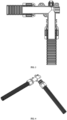
FIG. 1 is an exploded view of a modular fuel transfer pump flow passage structure; -
FIG. 2 is a schematic view of some parts inFIG. 1 ; -
FIG. 3 is a structural sectional view of a modular fuel transfer pump flow passage structure provided by the present invention; -
FIG. 4 is an assembly diagram of a modular fuel transfer pump flow passage structure provided by the present invention; -
FIG. 5 is a schematic structural view of the vent valve; -
FIG. 6 is a perspective view of a fuel transfer pump provided by the present invention; -
FIG. 7 is a sectional view of the connecting pipe and the pump; -
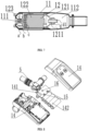
FIG. 8 is an explosion diagram at the control box; -
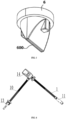
FIG. 9 is a schematic view of a gun nozzle; -
FIG. 10 is a cross-sectional view of the gun nozzle; -
FIG. 11 is a schematic diagram of a fuel transfer pump equipped with a nozzle sleeve. - In the following, the technical scheme in the embodiment of the application will be clearly and completely described with reference to the drawings in the embodiment of the application. Obviously, the described embodiment is only a part of the embodiment of the application, but not the whole embodiment. Based on the embodiments in this application, all other embodiments obtained by ordinary technicians in this field without creative labor belong to the protection scope of this application.
- Reference to "an example" or "an embodiment" herein means that a particular feature, structure or characteristic described in connection with an embodiment or an embodiment can be included in at least one embodiment of this application. The appearance of this phrase in various places in the specification does not necessarily refer to the same embodiment, nor is it an independent or alternative embodiment mutually exclusive with other embodiments. It is understood explicitly and implicitly by those skilled in the art that the embodiments described herein can be combined with other embodiments.
- In this specification, for the sake of convenience, words and expressions indicating orientation or positional relationship such as "middle", "upper", "lower", "front", "rear", "vertical", "horizontal", "top", "inner" and "outer" are used to illustrate the positional relationship of constituent elements with reference to the attached drawings, only for the convenience of description. The positional relationship of the constituent elements is appropriately changed according to the direction of the described constituent elements. Therefore, it is not limited to the words and expressions described in the specification, and can be replaced appropriately according to the situation.
- As shown in
FIG. 1 to FIG. 4 , the present invention provides a modular fuel transfer pump flow passage structure, which includes anoil inlet bellows 1, alead sealing plug 4, anadapter 5, anair vent valve 6 and anoil outlet bellows 10, wherein connection ports at both ends of theadapter 5 are respectively equipped and fixed with anoil inlet bellows 1 and anoil outlet bellows 10 by using fasteners; theadapter 5 is fixedly provided with anoil inlet pipe 100 of theoil inlet bellows 1, and an end wall surface in an axial direction of theadapter 5 is provided with avent hole 101; avent valve 6 equipped with avent cap 7 is arranged outside thevent hole 101; anoil outlet pipe 200 of theoil outlet bellows 10 is fixedly installed on theadapter 5, and athrough hole 201 is formed on the end wall surface in the axial direction of theadapter 5, and thelead sealing plug 4 is installed in the throughhole 201; an inner cavity wall of the fastener is opposite to the structure of the bellows, and a corrugated structure for wedging and fixing is also integrally formed; outer walls at the two ends of theadapter 5 are integrally formed withannular bosses 300 for the fastener to be fixedly installed. - The fastener for fixing the
oil inlet bellows 1 consists of a first fastener 2 and afirst mating part 3, while the fastener for fixing theoil outlet bellows 10 consists of a second fastener 8 and a second mating part 9; both theoil inlet bellows 1 and theoil outlet bellows 10 are corrugated hoses with a circular design; both the first fastener 2 and the second fastener 8 are integrally formed with inverted buttons to match the locking positions of thefirst mating part 3 and the second mating part 9 respectively; thevent valve 6 is a one-way normally closed soft rubber valve, and a mounting direction of one end with a normally closedvent 600 is toward the inner cavity of theadapter 5. In some embodiments (not shown in the figure), thevent valve 6 can also be a conventional valve with unlimited shape, as long as the valve ensures that the external air can flow into theadapter 5, and the high-pressure oil in theadapter 5 can make the valve and the valve seat close to each other to achieve sealing when working. - Compared with the existing fuel transfer pump integrated with the pump casing, the present invention adopts the modular design that all components are formed independently and can be assembled flexibly, and can be fixed on the pump casing after assembly, in which the main role is the adapter, which is connected with the oil inlet bellows, the oil outlet bellows, the vent hole provided with the vent valve and the lead sealing plug connected with the motor, so that the interfaces can be assembled more intuitively, simply and conveniently without mutual interference.
- It should be noted that the vent valve provided by the present invention is a normally closed unidirectional soft rubber valve which opens inward, and its functions and functions are as follows: when the motor of the fuel transfer pump stops working, the liquid in the flow passage will generate negative pressure due to gravity, and the atmospheric pressure at the outside of the vent valve will be greater than the negative pressure at the inside of the vent valve, and the valve will be opened to let gas enter the flow passage, so that the flow passage is disconnected, and the siphon phenomenon of the flow passage can be avoided; When the motor of the pump starts to work, because of the pressure in the flow passage, the pressure of the liquid inside the vent valve is greater than the atmospheric pressure outside the machine, which will make the valve stick more tightly and close tightly, so that the liquid will not leak out. A soft rubber material is selected as the manufacturing material of the vent valve because the soft rubber material combined with the one-way design structure of the vent valve can make the vent valve close to itself and keep the normally closed state without external pressure.
- As shown in
FIG. 6 to FIG. 10 , the present invention also provides a fuel transfer pump, which has the above-mentioned modular fuel transfer pump flow passage structure, and further includes a connectingpipe 11 arranged at a free end of theoil inlet bellows 1, a pump 12 built in the connectingpipe 11, agun nozzle 13 arranged at a free end of theoil outlet bellows 10 and acontrol box 14 arranged outside theadapter 5, wherein thecontrol box 14 is internally provided with aPCB board 141 and abattery 142 and is electrically connected with the pump 12 through wires; the pump 12 comprises an outer casing 121 and a built-inmotor 122, andimpellers 123 are arranged on an output shaft of themotor 122; themotor 122 is provided with a first sealing mechanism at one side close to aliquid inlet 111 of the connectingpipe 11, and themotor 122 is provided with a second sealing mechanism at one side close to a liquid outlet 112 of the connectingpipe 11; - The connection between the
oil inlet bellows 1 and the connectingpipe 11, and the connection between theoil outlet bellows 10 and thegun nozzle 13 are also realized by fasteners, so as to facilitate quick disassembly; the first sealing mechanism includes a gland a, the gland a is embedded and clamped at an end of the outer casing 121, an output end of themotor 122 is sleeved and connected with a motor shaft seal c, and the motor shaft seal c is embedded and installed inside the gland a; a rubber seal b is further arranged between the gland a and the outer casing 121; the second sealing mechanism comprises a rubber part d, and asealing part 1211 is formed on one side of the outer casing 121; one end of the rubber part d penetrates through the sealingpart 1211 and is clamped with an inner wall of the sealingpart 1211; an outer surface of the rubber part d is provided with a sealing hole d1 matched with an electric wiring of themotor 122, and an outer wall of the electric wiring of themotor 122 is fixedly connected with an inner wall of the sealing hole d1 in a sealed manner, so that the sealing performance of the electric wiring of themotor 122 can be improved; acontrol switch 15 and anindicator light 16 are embedded in an outer surface of thecontrol box 14 in sequence, and thecontrol switch 15 and theindicator light 16 are electrically connected with themotor 122; a DC socket is embedded in one side of an outer surface of thecontrol box 14, so as to realize external power connection; amounting pipe 131 is formed on one side of an inner wall of an output end of thegun nozzle 13, and a sensing shell is embedded in themounting pipe 131; aninfrared sensor 17 is installed in a cavity of the sensing shell, and theinfrared sensor 17 is connected to thecontrol box 13 by an electric wiring; a rubber sealing plug is further arranged between themounting pipe 131 and the sensing shell, and the electric wiring of theinfrared sensor 17 passes through the rubber sealing plug, and the sealing assembly is realized through the rubber sealing plug, so that theinfrared sensor 17 is completely sealed in the inner cavity of the sensing shell. - In the fuel transfer pump, through the first sealing mechanism and the second sealing mechanism, the end face and radial sealing are adopted, and the oil pressure and the clamping force of the gland are in the same direction, so that the sealing surface always has a pressing force acting, and the sealing performance of the motor can be improved; the on or off state of the motor can be clearly seen through the indicator light, and the infrared sensor is arranged outside the flow channel, so that it is not in direct contact with the liquid, thus avoiding the misjudgment reaction.
- The
nozzle 13 of the fuel transfer pump is also equipped with anozzle sleeve 18, as shown inFIG. 11 . Thenozzle sleeve 18 is connected to thenozzle 13 through afixing rope 19. When the fuel transfer pump is stored, thenozzle sleeve 18 is sleeved on thenozzle 13 to prevent residual oil from flowing out after the fuel transfer pump is used, and also to prevent impurities and dust from entering the internal flow passage of the fuel transfer pump to cause pollution. - The technical means disclosed in the scheme of the present invention are not limited to the technical means disclosed in the above embodiments, but also include the technical scheme composed of any combination of the above technical features. It should be pointed out that for those skilled in the art, several improvements and embellishments can be made without departing from the principle of the present invention, and these improvements and embellishments are also regarded as the protection scope of the present invention.
Claims (12)
- A modular fuel transfer pump flow passage structure, comprising an oil inlet bellows (1), a lead sealing plug (4), an adapter (5), an air vent valve (6) and an oil outlet bellows (10), wherein connection ports at both ends of the adapter (5) are respectively equipped and fixed with an oil inlet bellows (1) and an oil outlet bellows (10) by using fasteners; the adapter (5) is fixedly provided with an oil inlet pipe (100) of the oil inlet bellows (1), and an end wall surface in an axial direction of the adapter (5) is provided with a vent hole (101); a vent valve (6) equipped with a vent cap (7) is arranged outside the vent hole (101); an oil outlet pipe (200) of the oil outlet bellows (10) is fixedly installed on the adapter (5), and a through hole (201) is formed on the end wall surface in the axial direction of the adapter (5), and the lead sealing plug (4) is installed in the through hole (201); an inner cavity wall of the fastener is opposite to the structure of the bellows, and a corrugated structure for wedging and fixing is also integrally formed; outer walls at the two ends of the adapter (5) are integrally formed with annular bosses (300) for the fastener to be fixedly installed.
- The modular fuel transfer pump flow passage structure according to claim 1, wherein the fastener for fixing the oil inlet bellows (1) consists of a first fastener (2) and a first mating part (3), while the fastener for fixing the oil outlet bellows (10) consists of a second fastener (8) and a second mating part (9).
- The modular fuel transfer pump flow passage structure according to claim 1, wherein both the oil inlet bellows (1) and the oil outlet bellows (10) are corrugated hoses with a circular design.
- The modular fuel transfer pump flow passage structure according to claim 2, wherein both the first fastener (2) and the second fastener (8) are integrally formed with inverted buttons to match the locking positions of the first mating part (3) and the second mating part (9) respectively.
- The modular fuel transfer pump flow passage structure according to claim 1, wherein the vent valve (6) is a one-way normally closed soft rubber valve, and a mounting direction of one end with a normally closed vent (600) is toward the inner cavity of the adapter (5).
- A fuel transfer pump, comprising a modular fuel transfer pump flow passage structure, the modular fuel transfer pump flow passage structure comprising an oil inlet bellows (1), a lead sealing plug (4), an adapter (5), an air vent valve (6) and an oil outlet bellows (10), wherein connection ports at both ends of the adapter (5) are respectively equipped and fixed with an oil inlet bellows (1) and an oil outlet bellows (10) by using fasteners; the adapter (5) is fixedly provided with an oil inlet pipe (100) of the oil inlet bellows (1), and an end wall surface in an axial direction of the adapter (5) is provided with a vent hole (101); a vent valve (6) equipped with a vent cap (7) is arranged outside the vent hole (101); an oil outlet pipe (200) of the oil outlet bellows (10) is fixedly installed on the adapter (5), and a through hole (201) is formed on the end wall surface in the axial direction of the adapter (5), and the lead sealing plug (4) is installed in the through hole (201); an inner cavity wall of the fastener is opposite to the structure of the bellows, and a corrugated structure for wedging and fixing is also integrally formed; outer walls at the two ends of the adapter (5) are integrally formed with annular bosses (300) for the fastener to be fixedly installed; wherein,
the fuel transfer pump further comprises a connecting pipe (11) arranged at a free end of the oil inlet bellows (1), a pump (12) built in the connecting pipe (11), a gun nozzle (13) arranged at a free end of the oil outlet bellows (10) and a control box (14) arranged outside the adapter (5), wherein the control box (14) is internally provided with a PCB board (141) and a battery (142) and is electrically connected with the pump (12) through wires; the pump (12) comprises an outer casing (121) and a built-in motor (122), and impellers (123) are arranged on an output shaft of the motor (122); the motor (122) is provided with a first sealing mechanism at one side close to a liquid inlet (111) of the connecting pipe (11), and the motor (122) is provided with a second sealing mechanism at one side close to a liquid outlet (112) of the connecting pipe (11). - The fuel transfer pump according to claim 6, wherein the connection between the oil inlet bellows (1) and the connecting pipe (11), and the connection between the oil outlet bellows (10) and the gun nozzle (13) are also realized by fasteners, so as to facilitate quick disassembly.
- The fuel transfer pump according to claim 7, wherein the first sealing mechanism comprises a gland (a), the gland (a) is embedded and clamped at an end of the outer casing (121), an output end of the motor (122) is sleeved and connected with a motor shaft seal (c), and the motor shaft seal (c) is embedded and installed inside the gland (a); a rubber seal (b) is further arranged between the gland (a) and the outer casing (121); the second sealing mechanism comprises a rubber part (d), and a sealing part (1211) is formed on one side of the outer casing (121); one end of the rubber part (d) penetrates through the sealing part (1211) and is clamped with an inner wall of the sealing part (1211); an outer surface of the rubber part (d) is provided with a sealing hole (d1) matched with an electric wiring of the motor (122), and an outer wall of the electric wiring of the motor (122) is fixedly connected with an inner wall of the sealing hole (d1) in a sealed manner, so that the sealing performance of the electric wiring of the motor (122) can be improved.
- The fuel transfer pump according to claim 8, wherein a control switch (15) and an indicator light (16) are embedded in an outer surface of the control box (14) in sequence, and the control switch (15) and the indicator light (16) are electrically connected with the motor (122); a DC socket is embedded in one side of an outer surface of the control box (14), so as to realize external power connection.
- The fuel transfer pump according to claim 9, wherein a mounting pipe (131) is formed on one side of an inner wall of an output end of the gun nozzle (13), and a sensing shell is embedded in the mounting pipe (131); an infrared sensor (17) is installed in a cavity of the sensing shell, and the infrared sensor (17) is connected to the control box (13) by an electric wiring; a rubber sealing plug is further arranged between the mounting pipe (131) and the sensing shell, and the electric wiring of the infrared sensor (17) passes through the rubber sealing plug, and the sealing assembly is realized through the rubber sealing plug, so that the infrared sensor (17) is completely sealed in the inner cavity of the sensing shell.
- A fuel transfer pump, comprising an oil inlet bellows (1) and an oil outlet bellows (10) connected by an adapter (5), wherein the adapter (5) is provided with a lead sealing plug (4) and a vent valve (6), wherein the fuel transfer pump further comprises a connecting pipe (11) arranged at a free end of the oil inlet bellows (1), a pump (12) built in the connecting pipe (11), a gun nozzle (13) arranged at a free end of the oil outlet bellows (10) and a control box (14) arranged outside the adapter (5), wherein the control box (14) is internally provided with a PCB board (141) and a battery (142) and is electrically connected with the pump (12) through wires; the pump (12) comprises an outer casing (121) and a built-in motor (122), and impellers (123) are arranged on an output shaft of the motor (122); the motor (122) is provided with a first sealing mechanism at one side close to a liquid inlet (111) of the connecting pipe (11), and the motor (122) is provided with a second sealing mechanism at one side close to a liquid outlet (112) of the connecting pipe (11).
- The fuel transfer pump according to claim 11, wherein the first sealing mechanism comprises a gland (a), the gland (a) is embedded and clamped at an end of the outer casing (121), an output end of the motor (122) is sleeved and connected with a motor shaft seal (c), and the motor shaft seal (c) is embedded and installed inside the gland (a); a rubber seal (b) is further arranged between the gland (a) and the outer casing (121); the second sealing mechanism comprises a rubber part (d), and a sealing part (1211) is formed on one side of the outer casing (121); one end of the rubber part (d) penetrates through the sealing part (1211) and is clamped with an inner wall of the sealing part (1211); an outer surface of the rubber part (d) is provided with a sealing hole (d1) matched with an electric wiring of the motor (122), and an outer wall of the electric wiring of the motor (122) is fixedly connected with an inner wall of the sealing hole (d1) in a sealed manner, so that the sealing performance of the electric wiring of the motor (122) can be improved.
Applications Claiming Priority (1)
| Application Number | Priority Date | Filing Date | Title |
|---|---|---|---|
| US17/829,459 US11466689B1 (en) | 2022-06-01 | 2022-06-01 | Fuel pump |
Publications (3)
| Publication Number | Publication Date |
|---|---|
| EP4286679A1 true EP4286679A1 (en) | 2023-12-06 |
| EP4286679C0 EP4286679C0 (en) | 2025-09-17 |
| EP4286679B1 EP4286679B1 (en) | 2025-09-17 |
Family
ID=83547257
Family Applications (1)
| Application Number | Title | Priority Date | Filing Date |
|---|---|---|---|
| EP23176356.6A Active EP4286679B1 (en) | 2022-06-01 | 2023-05-31 | Modular fuel transfer pump flow passage structure and fuel transfer pump |
Country Status (2)
| Country | Link |
|---|---|
| US (1) | US11466689B1 (en) |
| EP (1) | EP4286679B1 (en) |
Families Citing this family (5)
| Publication number | Priority date | Publication date | Assignee | Title |
|---|---|---|---|---|
| US11725616B1 (en) | 2022-03-15 | 2023-08-15 | Delphi Technologies Ip Limited | Sealing ring gland and fuel pump including the same |
| US12607274B2 (en) * | 2023-11-11 | 2026-04-21 | Zhongshan Peili Technology Co., Ltd. | Fuel pump flow passage structure |
| CN119196063A (en) * | 2024-08-20 | 2024-12-27 | 南通锐莱新能源技术有限公司 | A centrifugal circulation pump with pressure regulation function |
| CN120332152A (en) * | 2025-05-06 | 2025-07-18 | 乐君敏 | A siphon and overflow prevention oil pump structure |
| US12589400B1 (en) * | 2025-10-24 | 2026-03-31 | Zhongshan Peili Technology Co., Ltd. | Liquid pumping device and liquid refilling apparatus |
Citations (8)
| Publication number | Priority date | Publication date | Assignee | Title |
|---|---|---|---|---|
| US4570833A (en) * | 1983-08-26 | 1986-02-18 | Vanderjagt John A | Pumping system |
| US4722556A (en) * | 1985-11-14 | 1988-02-02 | Toddco Partnership | Recreational vehicle sewerline adapter |
| US6352088B1 (en) * | 2000-10-17 | 2002-03-05 | Lannie L. Stegall | Vehicle wastewater drainage system |
| US7722091B1 (en) * | 2007-02-08 | 2010-05-25 | Camco Manufacturing, Inc. | RV waste discharge sewer line two-part adapter assembly with flexible seal and locking mechanism |
| US20150247504A1 (en) * | 2014-02-28 | 2015-09-03 | Flow Control Llc. | Bilge pump arrangement having back flow preventer |
| US20180258893A1 (en) * | 2017-03-13 | 2018-09-13 | Delphi Technologies Ip Limited | Fuel Pump and Fuel Supply System Using the Same |
| US10989198B1 (en) * | 2020-07-24 | 2021-04-27 | Fujian Aidi Electric Co., Ltd. | Detachable submersible pump with modular design |
| US20210388595A1 (en) * | 2020-06-16 | 2021-12-16 | FUJIAN AIDI ELECTRIC Co.,Ltd. | Sewage discharge device |
Family Cites Families (3)
| Publication number | Priority date | Publication date | Assignee | Title |
|---|---|---|---|---|
| US6063634A (en) * | 1998-04-01 | 2000-05-16 | Abbott Laboratories | Fluid assembly and method for diagnostic instrument |
| DE102014209157A1 (en) * | 2014-05-14 | 2015-11-19 | Wiwa Wilhelm Wagner Gmbh & Co Kg | Method for controlling a pump system and pump system |
| CN108050082B (en) * | 2018-01-31 | 2024-07-09 | 苏州优德通力科技有限公司 | Combined sewage pump with novel standby pump structure |
-
2022
- 2022-06-01 US US17/829,459 patent/US11466689B1/en active Active
-
2023
- 2023-05-31 EP EP23176356.6A patent/EP4286679B1/en active Active
Patent Citations (8)
| Publication number | Priority date | Publication date | Assignee | Title |
|---|---|---|---|---|
| US4570833A (en) * | 1983-08-26 | 1986-02-18 | Vanderjagt John A | Pumping system |
| US4722556A (en) * | 1985-11-14 | 1988-02-02 | Toddco Partnership | Recreational vehicle sewerline adapter |
| US6352088B1 (en) * | 2000-10-17 | 2002-03-05 | Lannie L. Stegall | Vehicle wastewater drainage system |
| US7722091B1 (en) * | 2007-02-08 | 2010-05-25 | Camco Manufacturing, Inc. | RV waste discharge sewer line two-part adapter assembly with flexible seal and locking mechanism |
| US20150247504A1 (en) * | 2014-02-28 | 2015-09-03 | Flow Control Llc. | Bilge pump arrangement having back flow preventer |
| US20180258893A1 (en) * | 2017-03-13 | 2018-09-13 | Delphi Technologies Ip Limited | Fuel Pump and Fuel Supply System Using the Same |
| US20210388595A1 (en) * | 2020-06-16 | 2021-12-16 | FUJIAN AIDI ELECTRIC Co.,Ltd. | Sewage discharge device |
| US10989198B1 (en) * | 2020-07-24 | 2021-04-27 | Fujian Aidi Electric Co., Ltd. | Detachable submersible pump with modular design |
Also Published As
| Publication number | Publication date |
|---|---|
| EP4286679C0 (en) | 2025-09-17 |
| EP4286679B1 (en) | 2025-09-17 |
| US11466689B1 (en) | 2022-10-11 |
Similar Documents
| Publication | Publication Date | Title |
|---|---|---|
| EP4286679A1 (en) | Modular fuel transfer pump flow passage structure and fuel transfer pump | |
| CN218620333U (en) | Electric oil-well pump with one-way air valve | |
| CN206546237U (en) | Airtight detection switching device for battery case | |
| CN111289167A (en) | A sensor for measuring the internal pressure of a tank for storing volatile liquids | |
| CN217784460U (en) | Practical efficient modularization oil pump runner access structure | |
| CN117704289B (en) | Remote control type underground pressure regulating system | |
| CN201152206Y (en) | Engine fuel control valve | |
| CN217277183U (en) | Multifunctional sampling tube for fixing pollution source | |
| US12607274B2 (en) | Fuel pump flow passage structure | |
| US20200262406A1 (en) | Watertight chamber type electric vacuum pump and vacuum boosting brake system | |
| CN215623809U (en) | Intelligent electric oil well pump | |
| CN223952779U (en) | Anti-siphon anti-overflow oil pump structure | |
| CN223104808U (en) | A power device and a smoke machine having the same | |
| US12473192B1 (en) | Anti-siphonage and anti-overflow fuel pump structure | |
| CN113043839A (en) | Integrated fuel tank assembly | |
| CN223104809U (en) | A power box assembly | |
| CN218816621U (en) | Engine intubation setting device | |
| CN2466479Y (en) | Safety quick gas connector | |
| CN223881726U (en) | Sealing structure of underwater mechanical arm | |
| CN217712840U (en) | Multipurpose small-sized oil pump | |
| CN223609431U (en) | A portable universal air nozzle | |
| CN208125332U (en) | Battery case air-leakage test aerator | |
| CN120332152A (en) | A siphon and overflow prevention oil pump structure | |
| CN223781527U (en) | Dust-proof carburetor air inlet structure | |
| CN224010199U (en) | A sealed sleeve type handle structure |
Legal Events
| Date | Code | Title | Description |
|---|---|---|---|
| PUAI | Public reference made under article 153(3) epc to a published international application that has entered the european phase |
Free format text: ORIGINAL CODE: 0009012 |
|
| STAA | Information on the status of an ep patent application or granted ep patent |
Free format text: STATUS: THE APPLICATION HAS BEEN PUBLISHED |
|
| AK | Designated contracting states |
Kind code of ref document: A1 Designated state(s): AL AT BE BG CH CY CZ DE DK EE ES FI FR GB GR HR HU IE IS IT LI LT LU LV MC ME MK MT NL NO PL PT RO RS SE SI SK SM TR |
|
| STAA | Information on the status of an ep patent application or granted ep patent |
Free format text: STATUS: REQUEST FOR EXAMINATION WAS MADE |
|
| 17P | Request for examination filed |
Effective date: 20240523 |
|
| RBV | Designated contracting states (corrected) |
Designated state(s): AL AT BE BG CH CY CZ DE DK EE ES FI FR GB GR HR HU IE IS IT LI LT LU LV MC ME MK MT NL NO PL PT RO RS SE SI SK SM TR |
|
| REG | Reference to a national code |
Ref country code: DE Ref legal event code: R079 Free format text: PREVIOUS MAIN CLASS: F02M0037080000 Ipc: F04B0017060000 Ref country code: DE Ref legal event code: R079 Ref document number: 602023006698 Country of ref document: DE Free format text: PREVIOUS MAIN CLASS: F02M0037080000 Ipc: F04B0017060000 |
|
| GRAP | Despatch of communication of intention to grant a patent |
Free format text: ORIGINAL CODE: EPIDOSNIGR1 |
|
| STAA | Information on the status of an ep patent application or granted ep patent |
Free format text: STATUS: GRANT OF PATENT IS INTENDED |
|
| RIC1 | Information provided on ipc code assigned before grant |
Ipc: F04B 53/22 20060101ALI20250402BHEP Ipc: F16L 27/08 20060101ALI20250402BHEP Ipc: F16L 11/15 20060101ALI20250402BHEP Ipc: F04D 29/42 20060101ALI20250402BHEP Ipc: F04D 29/08 20060101ALI20250402BHEP Ipc: F04D 15/00 20060101ALI20250402BHEP Ipc: F04D 13/08 20060101ALI20250402BHEP Ipc: F04D 13/06 20060101ALI20250402BHEP Ipc: F04D 9/00 20060101ALI20250402BHEP Ipc: F16L 25/00 20060101ALI20250402BHEP Ipc: F02M 37/08 20060101ALI20250402BHEP Ipc: F04D 3/00 20060101ALI20250402BHEP Ipc: F04B 53/16 20060101ALI20250402BHEP Ipc: F04B 17/06 20060101AFI20250402BHEP |
|
| INTG | Intention to grant announced |
Effective date: 20250414 |
|
| GRAS | Grant fee paid |
Free format text: ORIGINAL CODE: EPIDOSNIGR3 |
|
| GRAA | (expected) grant |
Free format text: ORIGINAL CODE: 0009210 |
|
| STAA | Information on the status of an ep patent application or granted ep patent |
Free format text: STATUS: THE PATENT HAS BEEN GRANTED |
|
| AK | Designated contracting states |
Kind code of ref document: B1 Designated state(s): AL AT BE BG CH CY CZ DE DK EE ES FI FR GB GR HR HU IE IS IT LI LT LU LV MC ME MK MT NL NO PL PT RO RS SE SI SK SM TR |
|
| REG | Reference to a national code |
Ref country code: GB Ref legal event code: FG4D |
|
| REG | Reference to a national code |
Ref country code: CH Ref legal event code: EP |
|
| REG | Reference to a national code |
Ref country code: IE Ref legal event code: FG4D |
|
| REG | Reference to a national code |
Ref country code: DE Ref legal event code: R096 Ref document number: 602023006698 Country of ref document: DE |
|
| U01 | Request for unitary effect filed |
Effective date: 20251016 |
|
| U07 | Unitary effect registered |
Designated state(s): AT BE BG DE DK EE FI FR IT LT LU LV MT NL PT RO SE SI Effective date: 20251022 |
|
| PG25 | Lapsed in a contracting state [announced via postgrant information from national office to epo] |
Ref country code: NO Free format text: LAPSE BECAUSE OF FAILURE TO SUBMIT A TRANSLATION OF THE DESCRIPTION OR TO PAY THE FEE WITHIN THE PRESCRIBED TIME-LIMIT Effective date: 20251217 |
|
| PG25 | Lapsed in a contracting state [announced via postgrant information from national office to epo] |
Ref country code: HR Free format text: LAPSE BECAUSE OF FAILURE TO SUBMIT A TRANSLATION OF THE DESCRIPTION OR TO PAY THE FEE WITHIN THE PRESCRIBED TIME-LIMIT Effective date: 20250917 |
|
| PG25 | Lapsed in a contracting state [announced via postgrant information from national office to epo] |
Ref country code: GR Free format text: LAPSE BECAUSE OF FAILURE TO SUBMIT A TRANSLATION OF THE DESCRIPTION OR TO PAY THE FEE WITHIN THE PRESCRIBED TIME-LIMIT Effective date: 20251218 |
|
| PG25 | Lapsed in a contracting state [announced via postgrant information from national office to epo] |
Ref country code: RS Free format text: LAPSE BECAUSE OF FAILURE TO SUBMIT A TRANSLATION OF THE DESCRIPTION OR TO PAY THE FEE WITHIN THE PRESCRIBED TIME-LIMIT Effective date: 20251217 |
|
| PG25 | Lapsed in a contracting state [announced via postgrant information from national office to epo] |
Ref country code: SM Free format text: LAPSE BECAUSE OF FAILURE TO SUBMIT A TRANSLATION OF THE DESCRIPTION OR TO PAY THE FEE WITHIN THE PRESCRIBED TIME-LIMIT Effective date: 20250917 |
|
| PG25 | Lapsed in a contracting state [announced via postgrant information from national office to epo] |
Ref country code: ES Free format text: LAPSE BECAUSE OF FAILURE TO SUBMIT A TRANSLATION OF THE DESCRIPTION OR TO PAY THE FEE WITHIN THE PRESCRIBED TIME-LIMIT Effective date: 20250917 |
|
| PG25 | Lapsed in a contracting state [announced via postgrant information from national office to epo] |
Ref country code: IS Free format text: LAPSE BECAUSE OF FAILURE TO SUBMIT A TRANSLATION OF THE DESCRIPTION OR TO PAY THE FEE WITHIN THE PRESCRIBED TIME-LIMIT Effective date: 20260117 |
|
| PG25 | Lapsed in a contracting state [announced via postgrant information from national office to epo] |
Ref country code: CZ Free format text: LAPSE BECAUSE OF FAILURE TO SUBMIT A TRANSLATION OF THE DESCRIPTION OR TO PAY THE FEE WITHIN THE PRESCRIBED TIME-LIMIT Effective date: 20250917 |
|
| PG25 | Lapsed in a contracting state [announced via postgrant information from national office to epo] |
Ref country code: PL Free format text: LAPSE BECAUSE OF FAILURE TO SUBMIT A TRANSLATION OF THE DESCRIPTION OR TO PAY THE FEE WITHIN THE PRESCRIBED TIME-LIMIT Effective date: 20250917 |
|
| PG25 | Lapsed in a contracting state [announced via postgrant information from national office to epo] |
Ref country code: SK Free format text: LAPSE BECAUSE OF FAILURE TO SUBMIT A TRANSLATION OF THE DESCRIPTION OR TO PAY THE FEE WITHIN THE PRESCRIBED TIME-LIMIT Effective date: 20250917 |
|
| U20 | Renewal fee for the european patent with unitary effect paid |
Year of fee payment: 4 Effective date: 20260323 |