EP4286670A1 - Fuel pressurization device - Google Patents
Fuel pressurization device Download PDFInfo
- Publication number
- EP4286670A1 EP4286670A1 EP23175339.3A EP23175339A EP4286670A1 EP 4286670 A1 EP4286670 A1 EP 4286670A1 EP 23175339 A EP23175339 A EP 23175339A EP 4286670 A1 EP4286670 A1 EP 4286670A1
- Authority
- EP
- European Patent Office
- Prior art keywords
- fuel
- pressurization device
- main body
- overflow
- channel
- Prior art date
- Legal status (The legal status is an assumption and is not a legal conclusion. Google has not performed a legal analysis and makes no representation as to the accuracy of the status listed.)
- Granted
Links
Images


Classifications
-
- F—MECHANICAL ENGINEERING; LIGHTING; HEATING; WEAPONS; BLASTING
- F02—COMBUSTION ENGINES; HOT-GAS OR COMBUSTION-PRODUCT ENGINE PLANTS
- F02M—SUPPLYING COMBUSTION ENGINES IN GENERAL WITH COMBUSTIBLE MIXTURES OR CONSTITUENTS THEREOF
- F02M37/00—Apparatus or systems for feeding liquid fuel from storage containers to carburettors or fuel-injection apparatus; Arrangements for purifying liquid fuel specially adapted for, or arranged on, internal-combustion engines
- F02M37/0076—Details of the fuel feeding system related to the fuel tank
- F02M37/0082—Devices inside the fuel tank other than fuel pumps or filters
-
- F—MECHANICAL ENGINEERING; LIGHTING; HEATING; WEAPONS; BLASTING
- F02—COMBUSTION ENGINES; HOT-GAS OR COMBUSTION-PRODUCT ENGINE PLANTS
- F02M—SUPPLYING COMBUSTION ENGINES IN GENERAL WITH COMBUSTIBLE MIXTURES OR CONSTITUENTS THEREOF
- F02M1/00—Carburettors with means for facilitating engine's starting or its idling below operational temperatures
- F02M1/16—Other means for enriching fuel-air mixture during starting; Priming cups; using different fuels for starting and normal operation
-
- F—MECHANICAL ENGINEERING; LIGHTING; HEATING; WEAPONS; BLASTING
- F02—COMBUSTION ENGINES; HOT-GAS OR COMBUSTION-PRODUCT ENGINE PLANTS
- F02B—INTERNAL-COMBUSTION PISTON ENGINES; COMBUSTION ENGINES IN GENERAL
- F02B63/00—Adaptations of engines for driving pumps, hand-held tools or electric generators; Portable combinations of engines with engine-driven devices
- F02B63/02—Adaptations of engines for driving pumps, hand-held tools or electric generators; Portable combinations of engines with engine-driven devices for hand-held tools
-
- F—MECHANICAL ENGINEERING; LIGHTING; HEATING; WEAPONS; BLASTING
- F02—COMBUSTION ENGINES; HOT-GAS OR COMBUSTION-PRODUCT ENGINE PLANTS
- F02M—SUPPLYING COMBUSTION ENGINES IN GENERAL WITH COMBUSTIBLE MIXTURES OR CONSTITUENTS THEREOF
- F02M37/00—Apparatus or systems for feeding liquid fuel from storage containers to carburettors or fuel-injection apparatus; Arrangements for purifying liquid fuel specially adapted for, or arranged on, internal-combustion engines
- F02M37/0011—Constructional details; Manufacturing or assembly of elements of fuel systems; Materials therefor
- F02M37/0023—Valves in the fuel supply and return system
Definitions
- the present disclosure relates to a fuel pressurization device that pressure-feeds starting fuel to an engine.
- fuel for starting an engine is sent to a carburetor by a priming pump, and the fuel is stored in the carburetor. Then, a recoil starter is activated, and the fuel stored in the carburetor is sent into the engine with a negative pressure of the engine.
- a recoil starter is activated, and the fuel stored in the carburetor is sent into the engine with a negative pressure of the engine.
- the fuel is simply sent into the carburetor by the priming pump, and the fuel is simply sent into the engine with the negative pressure of the engine.
- it is required to supply pressurized fuel necessary for starting the engine in order to improve the starting performance of the engine.
- the present disclosure describes a fuel pressurization device capable of pressure-feeding fuel necessary for starting to an engine to enhance startability of the engine.
- a fuel pressurization device (1) which is provided in an engine unit (100) including a pump (3), a valve (4), and an engine (2) and pressure-feeds starting fuel supplied from the pump (3) to the engine (2) via the valve (4), the fuel pressurization device (1) including: a fuel chamber forming portion (12 and 20) including a fuel chamber (R) to which the fuel is supplied from the pump (3) and whose internal volume is variable; and a spring (30) configured to bias the fuel chamber forming portion (12 and 20) such that the volume of the fuel chamber (R) decreases.”
- the fuel chamber forming portion (12 and 20) is biased by the spring (30), and thus the fuel supplied by the pump (3) is pressurized in the fuel chamber (R). Since it is necessary to pressurize the fuel, the valve (4) provided in the engine unit (100) is closed when the fuel is being supplied into the fuel chamber (R) by the pump (3). In this state, when the valve (4) provided in the engine unit (100) is opened to start the engine (2), the pressurized fuel is supplied to the engine (2). In this way, the fuel pressurization device (1) can pressure-feed the fuel necessary for starting to the engine (2) to enhance the startability of the engine (2).
- the above-described fuel pressurization device (1) may be [2] "The fuel pressurization device (1) according to the above-described [1], wherein the fuel chamber forming portion (12 and 20) includes an elastically deformable elastic body (20) in at least a part thereof, wherein the volume of the fuel chamber (R) changes as the elastic body (20) deforms, and wherein the spring (30) biases the elastic body (20)."
- the fuel pressurization device (1) can easily change the volume of the fuel chamber (R) using the elastic body (20).
- the above-described fuel pressurization device (1) may be [3] "The fuel pressurization device (1) according to the above-described [1] or [2], wherein an overflow channel (L13) is connected to a discharge channel (L12), through which the fuel sent out from the fuel chamber (R) passes, to branch off from the discharge channel (L12), and wherein the fuel pressurization device (1) further comprises an overflow valve (40) configured to switch between whether or not to flow the fuel in the overflow channel (L13)."
- the fuel pressurization device (1) can discharge surplus fuel supplied into the fuel chamber (R) by the pump (3) via the overflow valve (40) and the overflow channel (L13).
- the above-described fuel pressurization device (1) may be [4] "The fuel pressurization device (1) according to the above-described [3], wherein the overflow valve (40) includes a valve body (41) and a valve body spring (42) that biases the valve body (41) such that the flow of the fuel is cut off in the overflow channel (L13)."
- the fuel pressurization device (1) adjusts a balance between the biasing forces of the spring (30) that biases the fuel chamber forming portion (12 and 20) and the valve body spring (42) of the overflow valve 40, and thus it is possible to set the volume of the fuel chamber (R) to a desired volume.
- the fuel pressurization device (1) it is possible to set the volume of the fuel chamber (R) to a desired value simply by changing the balance between the biasing forces of the springs (30 and 42) without changing the fuel chamber forming portion (12 and 20). As a result, the fuel pressurization device (1) can be easily applied to these engines (2) even in a case where the amount of the starting fuel to be pressure-fed varies depending on the type of engine (2) or the like.
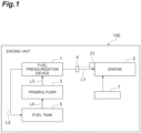
- a fuel pressurization device 1 is provided in an engine unit 100.
- the engine unit 100 may be mounted on, as an example, a brush cutter or the like.
- the engine unit 100 includes an engine 2, a priming pump (a pump) 3, and an electromagnetic valve (a valve) 4.
- the engine 2 may be, as an example, a two-cycle engine.
- the engine unit 100 appropriately includes a fuel supply device 7 for supplying fuel to the engine 2, a recoil starter 21, and the like.
- the fuel supply device 7 is, for example, a fuel pump or carburetor.
- the fuel pressurization device 1 pressure-feeds starting fuel supplied from the priming pump 3 to the engine 2 (for example, the inside of a crankcase or the inside of a combustion chamber) via the electromagnetic valve 4 (e.g., fuel valve).
- the electromagnetic valve 4 e.g., fuel valve
- the priming pump 3 is operated by the user of the engine unit 100 to supply the fuel from a fuel tank 5 to the fuel pressurization device 1.
- the priming pump 3 takes in the fuel from the fuel tank 5 via a pipe L4 and supplies the fuel to the fuel pressurization device 1 via a pipe L3.
- the electromagnetic valve 4 switches between whether or not to supply the starting fuel from the fuel pressurization device 1 to the engine 2.
- the electromagnetic valve 4 is provided in a pipe L1 (e.g., discharge pipe) for supplying the starting fuel from the fuel pressurization device 1 to the engine 2.
- the electromagnetic valve 4 is switched between an open state in which the fuel can flow through the pipe L1 and a closed state in which the flow of the fuel through the pipe L1 is cut off.
- the electromagnetic valve 4 is switched from the closed state to the open state when the engine 2 is started.
- the electromagnetic valve 4 may be switched from the closed state to the open state in conjunction with the operation of a recoil starter that is operated when the engine 2 is started.
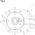
- the fuel pressurization device 1 takes in the fuel supplied from the priming pump 3 through an intake port S1. Then, the fuel pressurization device 1 discharges the taken-in fuel from a discharge port S2 and pressure-feeds the fuel to the engine 2. Further, the fuel pressurization device 1 has an overflow outlet port S3. The overflow outlet port S3 discharges surplus of the taken-in fuel to the outside.
- a nipple N1, a nipple N2, and a nipple N3 are attached to the intake port S1, the discharge port S2, and the overflow outlet port S3, respectively.
- the pipe L3 (see FIG. 1 ) is connected to the nipple N1.
- the pipe L1 see FIG.
- the pipe L2 (see FIG. 1 ) is connected to the nipple N2.
- the pipe L2 (see FIG. 1 ) is connected to the nipple N3.
- the pipe L2 serves as a flow channel for returning the surplus fuel discharged from the fuel pressurization device 1 to the fuel tank 5.
- the fuel pressurization device 1 includes a main body 10, an elastic body 20, a spring 30, and an overflow valve 40 (see FIG. 5 ).
- the main body 10 includes a first main body portion 11 and a second main body portion 12.
- Each of the first main body portion 11 and the second main body portion 12 has a substantially plate shape.
- the first main body portion 11 and the second main body portion 12 are overlapped each other with a gasket G interposed therebetween and are fixed to each other with a screw B1.
- the first main body portion 11 is provided with the discharge port S2.
- the second main body portion 12 is provided with the intake port S1 and the overflow outlet port S3.
- the first main body portion 11 is provided with a hole 11a penetrating in the overlapping direction of the first main body portion 11 and the second main body portion 12.
- the second main body portion 12 is provided with a recess 12a in a portion facing the hole 11a of the first main body portion 11.
- the elastic body 20 is disposed to cover the recess 12a of the second main body portion 12.
- the elastic body 20 is fixed by the edge of the elastic body 20 together with the gasket G being sandwiched between the first main body portion 11 and the second main body portion 12.
- the elastic body 20 is an elastically deformable member.
- the elastic body 20 is made of rubber or the like.
- the elastic body 20 is sheet-like.
- the fuel is supplied from the priming pump 3 to a space between the second main body portion 12 and the elastic body 20. That is, the space between the wall surface of the recess 12a of the second main body portion 12 and the elastic body 20 serves as a fuel chamber R to which the fuel is supplied.
- the fuel chamber R includes the elastic body 20 and the recess 12a of the second main body portion 12.
- the elastic body 20 is elastically deformable. Therefore, the volume of the fuel chamber R changes as the elastic body 20 deforms (see a difference between the fuel chambers R in FIGS. 4 and 5 ).
- FIG. 4 shows a state in which no fuel is being supplied into the fuel chamber R.
- FIG. 5 shows a state in which the fuel is being supplied into the fuel chamber R, the spring 30 is compressed, and the volume of the fuel chamber R becomes larger than the state shown in FIG. 4 .
- the second main body portion 12 and the elastic body 20 constitute a fuel chamber forming portion including the fuel chamber R to which the fuel is supplied from the priming pump 3 and whose internal volume is variable.
- the spring 30 is located between the first main body portion 11 and the elastic body 20.
- the spring 30 is disposed in the hole 11a of the first main body portion 11.
- the spring 30 is a compression spring.
- a substantially plate-like spring retainer 31 is attached to the outer surface of the first main body portion 11 with a screw B2.
- the spring retainer 31 covers the hole 11a of the first main body portion 11.
- One end portion of the spring 30 is in contact with the elastic body 20, and the other end portion of the spring 30 is in contact with the spring retainer 31. That is, the spring 30 biases the elastic body 20 toward the second main body portion 12 such that the volume of the fuel chamber R decreases.
- the spring 30 applies a pressure to the fuel in the fuel chamber R in a state where the fuel is being supplied into the fuel chamber R as shown in FIG. 5 .
- a spring pad 21 attached to the elastic body 20 may be provided between the elastic body 20 and the spring 30.
- the spring 30 bias the elastic body 20 so as to reduce the volume of the fuel chamber R.
- the spring 30 pressure-feeds the fuel in the fuel chamber R to the discharge port S2.
- the main body 10 is provided with an inflow channel L11, a discharge channel L12, and an overflow channel L13.
- the inflow channel L11 connects the intake port S1 and the fuel chamber R to each other.
- the inflow channel L11 is formed by a groove and a hole provided in the first main body portion 11 in the present embodiment.
- the inflow channel L11 guides the fuel supplied from the priming pump 3 to the intake port S1 via the pipe L3 to the fuel chamber R.
- the discharge channel L12 connects the fuel chamber R and the discharge port S2 to each other.
- the discharge channel L12 includes a first part L12a provided in the first main body portion 11 and a second part L12b provided in the second main body portion 12.
- the first part L12a and the second part L12b are formed by grooves or holes.
- the first part L12a is fluidly coupled with the discharge port S2.
- the second part L12b is fluidly coupled with the fuel chamber R and the first part L12a.
- the discharge channel L12 guides the fuel sent out from the fuel chamber R to the discharge port S2. That is, the fuel sent out from the fuel chamber R passes through the discharge channel L12.
- the overflow channel L13 connects the discharge channel L12 and the overflow outlet port S3 to each other. That is, the overflow channel L13 has one end portion connected to the discharge channel L12 to branch off from the discharge passage L12 and the other end portion connected to the overflow outlet port S3.
- the overflow channel L13 is formed by a hole provided in the first main body portion 11 and a hole provided in the second main body portion 12 in the present embodiment.
- the overflow valve 40 is provided in the overflow channel L13 and switches between whether or not to flow the fuel in the overflow channel L13.
- the overflow valve 40 is switched between an open state in which the fuel can flow through the overflow channel L13 and a closed state in which the flow of the fuel through the overflow channel L13 is cut off, depending on the pressure of the fuel in the fuel chamber R.
- the overflow channel L13 includes a small-diameter flow channel portion L13a connected to the discharge channel L12 and a large-diameter flow channel portion L13b connected to the small-diameter flow channel portion L13a.
- the large-diameter flow channel portion L13b has a larger flow channel cross-sectional area than the small-diameter flow channel portion L13a.
- the small-diameter flow channel portion L13a is positioned closer to the discharge channel L12 than the large-diameter flow channel portion L13b.
- the small-diameter flow channel portion L13a is provided in the first main body portion 11, and the large-diameter flow channel portion L13b is provided in the second main body portion 12.
- the overflow valve 40 opens and closes an opening portion L13c of the small-diameter flow channel portion L13a at a connection portion between the small-diameter flow channel portion L13a and the large-diameter flow channel portion L13b to switch between whether or not to flow the fuel in the overflow channel L13.
- the small-diameter flow channel portion L13a is an example of a first part of the overflow channel L13.
- the large-diameter flow channel portion L13b is an example of a second part of the overflow channel L13.
- the small-diameter flow channel portion L13a is fluidly coupled with the first part L12a of the discharge channel L12.
- the large-diameter flow channel portion L13b is fluidly coupled with the small-diameter flow channel portion L13a and the overflow outlet port S3.
- the overflow valve 40 includes a valve body 41 and a spring (a valve body spring) 42.
- the valve body 41 is provided in the large-diameter flow channel portion L13b and opens and closes the opening portion L13c of the small-diameter flow channel portion L13a.
- the spring 42 is a compression spring.
- the spring 42 biases the valve body 41 to cut off the flow of the fuel in the overflow channel L13.
- the spring 42 biases the valve body 41 such that the opening portion L13c of the small-diameter flow channel portion L13a is cut off by the valve body 41.
- One end portion of the spring 42 is in contact with the valve body 41, and the other end portion thereof is in contact with a spring retainer 13 provided in the second main body portion 12.
- the spring retainer 13 is attached to the second main body portion 12 with an O-ring interposed therebetween.
- a male screw portion 13a is provided on the outer peripheral surface of the spring retainer 13.
- a female screw portion 12b is provided on the inner peripheral surface of a hole portion in the second main body portion 12 into which the spring retainer 13 is fitted.
- the spring retainer 13 is attached to the second main body portion 12 by the male screw portion 13a engaging with the female screw portion 12b of the second main body portion 12.
- the spring 42 is compressed when the pressure of the fuel in the fuel chamber R becomes a predetermined pressure or more, and the valve body 41 separates from the opening portion L13c of the small-diameter flow channel portion L13a. As a result, the opening portion L13c is opened, and the fuel can flow through the overflow channel L13.
- the fuel in the fuel chamber R (surplus fuel) is returned from the fuel pressurization device 1 to the fuel tank 5 via the pipe L2 by being able to flow through the overflow channel L13.
- the operation of the fuel pressurization device 1 for pressure-feeding the starting fuel to the engine 2 when starting the engine 2 will be described. It is assumed that the electromagnetic valve 4 is closed before the engine 2 is started.
- the user of the engine unit 100 operates (presses) the priming pump 3 to start the engine 2.
- the fuel in the fuel tank 5 is sent to the intake port S1 of the fuel pressurization device 1 via the pipe L4, the priming pump 3, and the pipe L3, and the fuel is sent from the intake port S1 into the fuel chamber R via the inflow channel L11.
- the fuel sent into the fuel chamber R resists a biasing force of the spring 30 to push up the elastic body 20 (to move the elastic body 20 in a direction in which the spring 30 is compressed).
- the volume of the fuel chamber R increases, and the inside of the fuel chamber R is filled with the fuel.
- the fuel pressurization device 1 can store the fuel in the fuel chamber R. Further, the fuel stored in the fuel chamber R is biased by the spring 30 via the elastic body 20 and is in a pressurized state.
- the fuel sent to the fuel chamber R biases the valve body 41 of the overflow valve 40 via the discharge channel L12 and the overflow channel L13 (the small-diameter flow channel portion L13a).
- the spring 42 is set such that it starts to contract at a pressure higher than the pressure of the fuel in the fuel chamber R accumulated by the spring 30 by a predetermined value. That is, the spring 42 starts to contract after the spring 30 has contracted.
- the valve body 41 is biased by the fuel and the spring 42 is compressed, the valve body 41 separates from the opening portion L13c of the small-diameter flow channel portion L13a.
- the opening portion L13c is opened, and the fuel can flow through the overflow channel L13.
- the fuel is returned to the fuel tank 5 from the overflow channel L13 via the overflow outlet port S3 and the pipe L2. That is, the surplus fuel in the fuel chamber R is returned to the fuel tank 5 via the overflow channel L13, and the fuel in the fuel chamber R can be maintained at a predetermined pressure.
- the user starts the engine 2 by operating a recoil starter, for example.
- the electromagnetic valve 4 is changed from the closed state to the open state in conjunction with the operation of starting the engine 2.
- the starting fuel in the fuel chamber R pressurized by the spring 30 is vigorously sent (pressure-fed) to the engine 2 at once via the discharge channel L12 and the pipe L1. In this way, since the starting fuel is supplied at once when the engine 2 is started, startability of the engine 2 is improved.
- the elastic body 20 is biased by the spring 30, and thus the fuel supplied by the priming pump 3 is pressurized in the fuel chamber R. Since it is necessary to pressurize the fuel, the electromagnetic valve 4 provided in the engine unit 100 is closed when the fuel is being supplied into the fuel chamber R by the priming pump 3. In this state, when the electromagnetic valve 4 provided in the engine unit 100 is opened to start the engine 2, the pressurized fuel is vigorously supplied to the engine 2 at once. In this way, the fuel pressurization device 1 can pressure-feed the fuel necessary for starting to the engine 2 to enhance the startability of the engine 2.
- the fuel chamber R includes the elastically deformable elastic body 20 in at least a part thereof.
- the fuel pressurization device 1 can easily change the volume of the fuel chamber R using the elastic body 20.
- the fuel pressurization device 1 includes the overflow channel L13 that branches off from the discharge channel L12 and the overflow valve 40 that switches between whether or not to flow the fuel in the overflow channel L13. In this case, the fuel pressurization device 1 can discharge the surplus fuel supplied into the fuel chamber R by the priming pump 3 via the overflow valve 40 and the overflow channel L13.
- the overflow valve 40 controls a flow of the fuel into the overflow channel L13 based on a pressure in the discharge channel L12.
- the overflow valve 40 includes the valve body 41 and the spring 42 that biases the valve body 41.
- the fuel pressurization device 1 adjusts a balance between the biasing forces of the spring 30 that biases the elastic body 20 and the spring 42 of the overflow valve 40, and thus it is possible to set the volume of the fuel chamber R to a desired volume. That is, in the fuel pressurization device 1, it is possible to set the volume of the fuel chamber R to a desired value simply by changing the balance between the biasing forces of the springs 30 and 42 without changing the second main body portion 12 (the recess 12a) and the elastic body 20. As a result, the fuel pressurization device 1 can be easily applied to these engines 2 even in a case where the amount of the starting fuel to be pressure-fed varies depending on the type of engine 2 or the like.
- the pump for sending the fuel to the fuel chamber R is not limited to the priming pump 3. Any other type of pump may be used instead of the priming pump 3 as long as it can send the fuel to the fuel chamber R of the fuel pressurization device 1.
- the electromagnetic valve 4 is not limited to an electromagnetic valve, and any other type of valve may be used.
Landscapes
- Engineering & Computer Science (AREA)
- Chemical & Material Sciences (AREA)
- Combustion & Propulsion (AREA)
- Mechanical Engineering (AREA)
- General Engineering & Computer Science (AREA)
- Fuel-Injection Apparatus (AREA)
Abstract
Description
- The disclosure is based upon and claims the benefit of priority from
Japanese Patent Application No. 2022-087625, filed on May/30/2022 - The present disclosure relates to a fuel pressurization device that pressure-feeds starting fuel to an engine.
- For example, in an engine unit mounted on a brush cutter or the like, fuel for starting an engine is sent to a carburetor by a priming pump, and the fuel is stored in the carburetor. Then, a recoil starter is activated, and the fuel stored in the carburetor is sent into the engine with a negative pressure of the engine. An engine unit having such a configuration is described, for example, in
Japanese Patent Publication No. 2019-52593 - In the engine unit described above, the fuel is simply sent into the carburetor by the priming pump, and the fuel is simply sent into the engine with the negative pressure of the engine. In such an engine unit, it is required to supply pressurized fuel necessary for starting the engine in order to improve the starting performance of the engine.
- Accordingly, the present disclosure describes a fuel pressurization device capable of pressure-feeding fuel necessary for starting to an engine to enhance startability of the engine.
- An aspect of the present disclosure is [1] "A fuel pressurization device (1) which is provided in an engine unit (100) including a pump (3), a valve (4), and an engine (2) and pressure-feeds starting fuel supplied from the pump (3) to the engine (2) via the valve (4), the fuel pressurization device (1) including: a fuel chamber forming portion (12 and 20) including a fuel chamber (R) to which the fuel is supplied from the pump (3) and whose internal volume is variable; and a spring (30) configured to bias the fuel chamber forming portion (12 and 20) such that the volume of the fuel chamber (R) decreases."
- In the fuel pressurization device (1), the fuel chamber forming portion (12 and 20) is biased by the spring (30), and thus the fuel supplied by the pump (3) is pressurized in the fuel chamber (R). Since it is necessary to pressurize the fuel, the valve (4) provided in the engine unit (100) is closed when the fuel is being supplied into the fuel chamber (R) by the pump (3). In this state, when the valve (4) provided in the engine unit (100) is opened to start the engine (2), the pressurized fuel is supplied to the engine (2). In this way, the fuel pressurization device (1) can pressure-feed the fuel necessary for starting to the engine (2) to enhance the startability of the engine (2).
- The above-described fuel pressurization device (1) may be [2] "The fuel pressurization device (1) according to the above-described [1], wherein the fuel chamber forming portion (12 and 20) includes an elastically deformable elastic body (20) in at least a part thereof, wherein the volume of the fuel chamber (R) changes as the elastic body (20) deforms, and wherein the spring (30) biases the elastic body (20)." In this case, the fuel pressurization device (1) can easily change the volume of the fuel chamber (R) using the elastic body (20).
- The above-described fuel pressurization device (1) may be [3] "The fuel pressurization device (1) according to the above-described [1] or [2], wherein an overflow channel (L13) is connected to a discharge channel (L12), through which the fuel sent out from the fuel chamber (R) passes, to branch off from the discharge channel (L12), and wherein the fuel pressurization device (1) further comprises an overflow valve (40) configured to switch between whether or not to flow the fuel in the overflow channel (L13)." In this case, the fuel pressurization device (1) can discharge surplus fuel supplied into the fuel chamber (R) by the pump (3) via the overflow valve (40) and the overflow channel (L13).
- The above-described fuel pressurization device (1) may be [4] "The fuel pressurization device (1) according to the above-described [3], wherein the overflow valve (40) includes a valve body (41) and a valve body spring (42) that biases the valve body (41) such that the flow of the fuel is cut off in the overflow channel (L13)." In this case, the fuel pressurization device (1) adjusts a balance between the biasing forces of the spring (30) that biases the fuel chamber forming portion (12 and 20) and the valve body spring (42) of the
overflow valve 40, and thus it is possible to set the volume of the fuel chamber (R) to a desired volume. That is, in the fuel pressurization device (1), it is possible to set the volume of the fuel chamber (R) to a desired value simply by changing the balance between the biasing forces of the springs (30 and 42) without changing the fuel chamber forming portion (12 and 20). As a result, the fuel pressurization device (1) can be easily applied to these engines (2) even in a case where the amount of the starting fuel to be pressure-fed varies depending on the type of engine (2) or the like. - According to the aspect of the present disclosure, it is possible to pressure-feed fuel necessary for starting to an engine to enhance startability of the engine.
-
-
FIG. 1 is a block diagram showing an engine unit provided with a fuel pressurization device according to an embodiment. -
FIG. 2 is a front view of the fuel pressurization device. -
FIG. 3 is a side view of the fuel pressurization device viewed from an intake port side. -
FIG. 4 is a cross-sectional view along line A-B-C-A ofFIG. 2 . -
FIG. 5 is a cross-sectional view along line A-D-E-F inFIG. 2 . -
FIG. 6 is a cross-sectional view along line A-B-C-A inFIG. 2 , showing how fuel is supplied into a fuel chamber. -
FIG. 7 is a cross-sectional view along line A-D-E-F inFIG. 2 , showing how the fuel supplied to the fuel chamber is discharged from an overflow channel. -
FIG. 8 is a cross-sectional view along line A-D-E-F inFIG. 2 , showing how the fuel in the fuel chamber is supplied to the engine via a discharge channel. - Embodiments of the present disclosure will be described below with reference to the drawings. In the drawings, the same or corresponding elements are denoted by the same reference signs, and redundant description will be omitted.
- As shown in
FIG. 1 , afuel pressurization device 1 according to the present embodiment is provided in anengine unit 100. Theengine unit 100 may be mounted on, as an example, a brush cutter or the like. Theengine unit 100 includes anengine 2, a priming pump (a pump) 3, and an electromagnetic valve (a valve) 4. Theengine 2 may be, as an example, a two-cycle engine. Further, theengine unit 100 appropriately includes afuel supply device 7 for supplying fuel to theengine 2, arecoil starter 21, and the like. Thefuel supply device 7 is, for example, a fuel pump or carburetor. - When the
engine 2 is started, thefuel pressurization device 1 pressure-feeds starting fuel supplied from thepriming pump 3 to the engine 2 (for example, the inside of a crankcase or the inside of a combustion chamber) via the electromagnetic valve 4 (e.g., fuel valve). The following description focuses on a configuration in which thefuel pressurization device 1 pressure-feeds the starting fuel. - The
priming pump 3 is operated by the user of theengine unit 100 to supply the fuel from a fuel tank 5 to thefuel pressurization device 1. Here, thepriming pump 3 takes in the fuel from the fuel tank 5 via a pipe L4 and supplies the fuel to thefuel pressurization device 1 via a pipe L3. - The
electromagnetic valve 4 switches between whether or not to supply the starting fuel from thefuel pressurization device 1 to theengine 2. Here, theelectromagnetic valve 4 is provided in a pipe L1 (e.g., discharge pipe) for supplying the starting fuel from thefuel pressurization device 1 to theengine 2. Theelectromagnetic valve 4 is switched between an open state in which the fuel can flow through the pipe L1 and a closed state in which the flow of the fuel through the pipe L1 is cut off. Theelectromagnetic valve 4 is switched from the closed state to the open state when theengine 2 is started. For example, theelectromagnetic valve 4 may be switched from the closed state to the open state in conjunction with the operation of a recoil starter that is operated when theengine 2 is started. - As shown in
FIGS. 2 and3 , thefuel pressurization device 1 takes in the fuel supplied from thepriming pump 3 through an intake port S1. Then, thefuel pressurization device 1 discharges the taken-in fuel from a discharge port S2 and pressure-feeds the fuel to theengine 2. Further, thefuel pressurization device 1 has an overflow outlet port S3. The overflow outlet port S3 discharges surplus of the taken-in fuel to the outside. A nipple N1, a nipple N2, and a nipple N3 are attached to the intake port S1, the discharge port S2, and the overflow outlet port S3, respectively. The pipe L3 (seeFIG. 1 ) is connected to the nipple N1. The pipe L1 (seeFIG. 1 ) is connected to the nipple N2. The pipe L2 (seeFIG. 1 ) is connected to the nipple N3. The pipe L2 serves as a flow channel for returning the surplus fuel discharged from thefuel pressurization device 1 to the fuel tank 5. - More specifically, as shown in
FIGS. 4 and5 , thefuel pressurization device 1 includes amain body 10, anelastic body 20, aspring 30, and an overflow valve 40 (seeFIG. 5 ). In the present embodiment, themain body 10 includes a firstmain body portion 11 and a secondmain body portion 12. Each of the firstmain body portion 11 and the secondmain body portion 12 has a substantially plate shape. The firstmain body portion 11 and the secondmain body portion 12 are overlapped each other with a gasket G interposed therebetween and are fixed to each other with a screw B1. The firstmain body portion 11 is provided with the discharge port S2. The secondmain body portion 12 is provided with the intake port S1 and the overflow outlet port S3. - The first
main body portion 11 is provided with ahole 11a penetrating in the overlapping direction of the firstmain body portion 11 and the secondmain body portion 12. The secondmain body portion 12 is provided with arecess 12a in a portion facing thehole 11a of the firstmain body portion 11. - The
elastic body 20 is disposed to cover therecess 12a of the secondmain body portion 12. In the present embodiment, theelastic body 20 is fixed by the edge of theelastic body 20 together with the gasket G being sandwiched between the firstmain body portion 11 and the secondmain body portion 12. Theelastic body 20 is an elastically deformable member. For example, theelastic body 20 is made of rubber or the like. Theelastic body 20 is sheet-like. - Here, the fuel is supplied from the
priming pump 3 to a space between the secondmain body portion 12 and theelastic body 20. That is, the space between the wall surface of therecess 12a of the secondmain body portion 12 and theelastic body 20 serves as a fuel chamber R to which the fuel is supplied. For example, the fuel chamber R includes theelastic body 20 and therecess 12a of the secondmain body portion 12. Moreover, as described above, theelastic body 20 is elastically deformable. Therefore, the volume of the fuel chamber R changes as theelastic body 20 deforms (see a difference between the fuel chambers R inFIGS. 4 and5 ). -
FIG. 4 shows a state in which no fuel is being supplied into the fuel chamber R. Further,FIG. 5 shows a state in which the fuel is being supplied into the fuel chamber R, thespring 30 is compressed, and the volume of the fuel chamber R becomes larger than the state shown inFIG. 4 . In this way, the secondmain body portion 12 and theelastic body 20 constitute a fuel chamber forming portion including the fuel chamber R to which the fuel is supplied from thepriming pump 3 and whose internal volume is variable. - As shown in
FIG. 4 , thespring 30 is located between the firstmain body portion 11 and theelastic body 20. Thespring 30 is disposed in thehole 11a of the firstmain body portion 11. Thespring 30 is a compression spring. A substantially plate-like spring retainer 31 is attached to the outer surface of the firstmain body portion 11 with a screw B2. Thespring retainer 31 covers thehole 11a of the firstmain body portion 11. One end portion of thespring 30 is in contact with theelastic body 20, and the other end portion of thespring 30 is in contact with thespring retainer 31. That is, thespring 30 biases theelastic body 20 toward the secondmain body portion 12 such that the volume of the fuel chamber R decreases. In this way, thespring 30 applies a pressure to the fuel in the fuel chamber R in a state where the fuel is being supplied into the fuel chamber R as shown inFIG. 5 . Aspring pad 21 attached to theelastic body 20 may be provided between theelastic body 20 and thespring 30. Thespring 30 bias theelastic body 20 so as to reduce the volume of the fuel chamber R. Thespring 30 pressure-feeds the fuel in the fuel chamber R to the discharge port S2. - Further, as shown in
FIGS. 4 and5 , themain body 10 is provided with an inflow channel L11, a discharge channel L12, and an overflow channel L13. As shown inFIG. 4 , the inflow channel L11 connects the intake port S1 and the fuel chamber R to each other. The inflow channel L11 is formed by a groove and a hole provided in the firstmain body portion 11 in the present embodiment. The inflow channel L11 guides the fuel supplied from thepriming pump 3 to the intake port S1 via the pipe L3 to the fuel chamber R. - As shown in
FIG. 5 , the discharge channel L12 connects the fuel chamber R and the discharge port S2 to each other. In the present embodiment, the discharge channel L12 includes a first part L12a provided in the firstmain body portion 11 and a second part L12b provided in the secondmain body portion 12. The first part L12a and the second part L12b are formed by grooves or holes. The first part L12a is fluidly coupled with the discharge port S2. The second part L12b is fluidly coupled with the fuel chamber R and the first part L12a. The discharge channel L12 guides the fuel sent out from the fuel chamber R to the discharge port S2. That is, the fuel sent out from the fuel chamber R passes through the discharge channel L12. - The overflow channel L13 connects the discharge channel L12 and the overflow outlet port S3 to each other. That is, the overflow channel L13 has one end portion connected to the discharge channel L12 to branch off from the discharge passage L12 and the other end portion connected to the overflow outlet port S3. The overflow channel L13 is formed by a hole provided in the first
main body portion 11 and a hole provided in the secondmain body portion 12 in the present embodiment. - In the present embodiment, the
overflow valve 40 is provided in the overflow channel L13 and switches between whether or not to flow the fuel in the overflow channel L13. Here, theoverflow valve 40 is switched between an open state in which the fuel can flow through the overflow channel L13 and a closed state in which the flow of the fuel through the overflow channel L13 is cut off, depending on the pressure of the fuel in the fuel chamber R. - Here, the overflow channel L13 includes a small-diameter flow channel portion L13a connected to the discharge channel L12 and a large-diameter flow channel portion L13b connected to the small-diameter flow channel portion L13a. The large-diameter flow channel portion L13b has a larger flow channel cross-sectional area than the small-diameter flow channel portion L13a. In addition, the small-diameter flow channel portion L13a is positioned closer to the discharge channel L12 than the large-diameter flow channel portion L13b. In the present embodiment, the small-diameter flow channel portion L13a is provided in the first
main body portion 11, and the large-diameter flow channel portion L13b is provided in the secondmain body portion 12. In the present embodiment, theoverflow valve 40 opens and closes an opening portion L13c of the small-diameter flow channel portion L13a at a connection portion between the small-diameter flow channel portion L13a and the large-diameter flow channel portion L13b to switch between whether or not to flow the fuel in the overflow channel L13. - The small-diameter flow channel portion L13a is an example of a first part of the overflow channel L13. The large-diameter flow channel portion L13b is an example of a second part of the overflow channel L13. The small-diameter flow channel portion L13a is fluidly coupled with the first part L12a of the discharge channel L12. The large-diameter flow channel portion L13b is fluidly coupled with the small-diameter flow channel portion L13a and the overflow outlet port S3.
- More specifically, the
overflow valve 40 includes avalve body 41 and a spring (a valve body spring) 42. Thevalve body 41 is provided in the large-diameter flow channel portion L13b and opens and closes the opening portion L13c of the small-diameter flow channel portion L13a. Thespring 42 is a compression spring. Thespring 42 biases thevalve body 41 to cut off the flow of the fuel in the overflow channel L13. Here, thespring 42 biases thevalve body 41 such that the opening portion L13c of the small-diameter flow channel portion L13a is cut off by thevalve body 41. One end portion of thespring 42 is in contact with thevalve body 41, and the other end portion thereof is in contact with aspring retainer 13 provided in the secondmain body portion 12. Thespring retainer 13 is attached to the secondmain body portion 12 with an O-ring interposed therebetween. Here, as an example, amale screw portion 13a is provided on the outer peripheral surface of thespring retainer 13. Afemale screw portion 12b is provided on the inner peripheral surface of a hole portion in the secondmain body portion 12 into which thespring retainer 13 is fitted. Thespring retainer 13 is attached to the secondmain body portion 12 by themale screw portion 13a engaging with thefemale screw portion 12b of the secondmain body portion 12. - In the
overflow valve 40, thespring 42 is compressed when the pressure of the fuel in the fuel chamber R becomes a predetermined pressure or more, and thevalve body 41 separates from the opening portion L13c of the small-diameter flow channel portion L13a. As a result, the opening portion L13c is opened, and the fuel can flow through the overflow channel L13. In this case, the fuel in the fuel chamber R (surplus fuel) is returned from thefuel pressurization device 1 to the fuel tank 5 via the pipe L2 by being able to flow through the overflow channel L13. - Next, the operation of the
fuel pressurization device 1 for pressure-feeding the starting fuel to theengine 2 when starting theengine 2 will be described. It is assumed that theelectromagnetic valve 4 is closed before theengine 2 is started. First, the user of theengine unit 100 operates (presses) thepriming pump 3 to start theengine 2. As a result, the fuel in the fuel tank 5 is sent to the intake port S1 of thefuel pressurization device 1 via the pipe L4, thepriming pump 3, and the pipe L3, and the fuel is sent from the intake port S1 into the fuel chamber R via the inflow channel L11. - When the user further operates the
priming pump 3 to send the fuel to thefuel pressurization device 1, as shown inFIG. 6 , the fuel sent into the fuel chamber R resists a biasing force of thespring 30 to push up the elastic body 20 (to move theelastic body 20 in a direction in which thespring 30 is compressed). As a result, the volume of the fuel chamber R increases, and the inside of the fuel chamber R is filled with the fuel. In this state, the fuel in the fuel chamber R is not sent to theengine 2 because theelectromagnetic valve 4 is closed. That is, thefuel pressurization device 1 can store the fuel in the fuel chamber R. Further, the fuel stored in the fuel chamber R is biased by thespring 30 via theelastic body 20 and is in a pressurized state. - When the user further operates the
priming pump 3 to send the fuel to thefuel pressurization device 1, as shown inFIG. 7 , the fuel sent to the fuel chamber R biases thevalve body 41 of theoverflow valve 40 via the discharge channel L12 and the overflow channel L13 (the small-diameter flow channel portion L13a). Thespring 42 is set such that it starts to contract at a pressure higher than the pressure of the fuel in the fuel chamber R accumulated by thespring 30 by a predetermined value. That is, thespring 42 starts to contract after thespring 30 has contracted. When thevalve body 41 is biased by the fuel and thespring 42 is compressed, thevalve body 41 separates from the opening portion L13c of the small-diameter flow channel portion L13a. As a result, the opening portion L13c is opened, and the fuel can flow through the overflow channel L13. In this state, the fuel is returned to the fuel tank 5 from the overflow channel L13 via the overflow outlet port S3 and the pipe L2. That is, the surplus fuel in the fuel chamber R is returned to the fuel tank 5 via the overflow channel L13, and the fuel in the fuel chamber R can be maintained at a predetermined pressure. - After the fuel is stored in the fuel chamber R, the user starts the
engine 2 by operating a recoil starter, for example. Theelectromagnetic valve 4 is changed from the closed state to the open state in conjunction with the operation of starting theengine 2. As a result, as shown inFIG. 8 , the starting fuel in the fuel chamber R pressurized by thespring 30 is vigorously sent (pressure-fed) to theengine 2 at once via the discharge channel L12 and the pipe L1. In this way, since the starting fuel is supplied at once when theengine 2 is started, startability of theengine 2 is improved. - As described above, in the
fuel pressurization device 1, theelastic body 20 is biased by thespring 30, and thus the fuel supplied by thepriming pump 3 is pressurized in the fuel chamber R. Since it is necessary to pressurize the fuel, theelectromagnetic valve 4 provided in theengine unit 100 is closed when the fuel is being supplied into the fuel chamber R by thepriming pump 3. In this state, when theelectromagnetic valve 4 provided in theengine unit 100 is opened to start theengine 2, the pressurized fuel is vigorously supplied to theengine 2 at once. In this way, thefuel pressurization device 1 can pressure-feed the fuel necessary for starting to theengine 2 to enhance the startability of theengine 2. - The fuel chamber R includes the elastically deformable
elastic body 20 in at least a part thereof. In this case, thefuel pressurization device 1 can easily change the volume of the fuel chamber R using theelastic body 20. - The
fuel pressurization device 1 includes the overflow channel L13 that branches off from the discharge channel L12 and theoverflow valve 40 that switches between whether or not to flow the fuel in the overflow channel L13. In this case, thefuel pressurization device 1 can discharge the surplus fuel supplied into the fuel chamber R by thepriming pump 3 via theoverflow valve 40 and the overflow channel L13. - The
overflow valve 40 controls a flow of the fuel into the overflow channel L13 based on a pressure in the discharge channel L12. Theoverflow valve 40 includes thevalve body 41 and thespring 42 that biases thevalve body 41. In this case, thefuel pressurization device 1 adjusts a balance between the biasing forces of thespring 30 that biases theelastic body 20 and thespring 42 of theoverflow valve 40, and thus it is possible to set the volume of the fuel chamber R to a desired volume. That is, in thefuel pressurization device 1, it is possible to set the volume of the fuel chamber R to a desired value simply by changing the balance between the biasing forces of thesprings recess 12a) and theelastic body 20. As a result, thefuel pressurization device 1 can be easily applied to theseengines 2 even in a case where the amount of the starting fuel to be pressure-fed varies depending on the type ofengine 2 or the like. - Although the embodiments of the present disclosure have been described above, the present disclosure is not limited to the above embodiments. For example, the pump for sending the fuel to the fuel chamber R is not limited to the
priming pump 3. Any other type of pump may be used instead of thepriming pump 3 as long as it can send the fuel to the fuel chamber R of thefuel pressurization device 1. Further, theelectromagnetic valve 4 is not limited to an electromagnetic valve, and any other type of valve may be used.
Claims (10)
- A fuel pressurization device (1) which is provided in an engine unit (100) including a pump (3), a valve (4), and an engine (2) and pressure-feeds starting fuel supplied from the pump (3) to the engine (2) via the valve (4), the fuel pressurization device (1) comprising:a fuel chamber forming portion (12 and 20) including a fuel chamber (R) to which the fuel is supplied from the pump (3) and whose internal volume is variable; anda spring (30) configured to bias the fuel chamber forming portion (12 and 20) such that the volume of the fuel chamber (R) decreases.
- The fuel pressurization device (1) according to claim 1,wherein the fuel chamber forming portion (12 and 20) includes an elastically deformable elastic body (20) in at least a part thereof,wherein the volume of the fuel chamber (R) changes as the elastic body (20) deforms, andwherein the spring (30) biases the elastic body (20).
- The fuel pressurization device (1) according to claim 1 or 2,wherein an overflow channel (L13) is connected to a discharge channel (L12), through which the fuel sent out from the fuel chamber (R) passes, to branch off from the discharge channel (L12), andwherein the fuel pressurization device (1) further comprises an overflow valve (40) configured to switch between whether or not to flow the fuel in the overflow channel (L13).
- The fuel pressurization device (1) according to claim 3, wherein the overflow valve (40) includes a valve body (41) and a valve body spring (42) that biases the valve body (41) such that a flow of the fuel is cut off in the overflow channel (L13).
- The fuel pressurization device (1) according to any one of claims 1 to 4, wherein the elastic body (20) is sheet-like.
- The fuel pressurization device (1) according to claim 1, further comprising a main body (10) including a discharge port (S2),
Wherein the fuel chamber (R) located inside the main body (10) and fluidly coupled with the discharge port (S2). - The fuel pressurization device (1) according to claim 6,wherein the main body (1) comprising;a first main body portion (11) including the discharge port (S2), anda second main body portion (12) including a recess (12a) of the fuel chamber (R), andan elastic body (20) located between the first main body portion (11) and the second main body portion (12) so as to cover the recess (12a).
- The fuel pressurization device (1) according to claim 7,wherein the first main body portion (11) includes a first part (L12a) of a discharge channel (L12) fluidly coupled with the discharge port (S2), andwherein the second main body portion (12) includes a second part (L12b) of the discharge channel (L12) fluidly coupled with the first part (L12a) of the discharge channel (L12) and the fuel chamber (R).
- The fuel pressurization device (1) according to claim 8,wherein the first main body portion (11) includes a first part (L13a) of an overflow channel (L13) fluidly coupled with the first part (L12a) of the discharge channel (L12), andwherein the second main body portion (12) includes an overflow port (S3), and a second part (L13b) of the overflow channel (L13) fluidly coupled with the first part (L13a) of the overflow channel (L13) and the overflow port (S3).
- The fuel pressurization device (1) according to any one of claims 7 to 9,
wherein the spring (30) is located between the elastic body (20) and the first main body portion (11).
Applications Claiming Priority (1)
| Application Number | Priority Date | Filing Date | Title |
|---|---|---|---|
| JP2022087625A JP7813188B2 (en) | 2022-05-30 | 2022-05-30 | Fuel pressurization device |
Publications (3)
| Publication Number | Publication Date |
|---|---|
| EP4286670A1 true EP4286670A1 (en) | 2023-12-06 |
| EP4286670B1 EP4286670B1 (en) | 2025-10-29 |
| EP4286670C0 EP4286670C0 (en) | 2025-10-29 |
Family
ID=86604053
Family Applications (1)
| Application Number | Title | Priority Date | Filing Date |
|---|---|---|---|
| EP23175339.3A Active EP4286670B1 (en) | 2022-05-30 | 2023-05-25 | Fuel pressurization device |
Country Status (3)
| Country | Link |
|---|---|
| US (1) | US12012914B2 (en) |
| EP (1) | EP4286670B1 (en) |
| JP (1) | JP7813188B2 (en) |
Citations (4)
| Publication number | Priority date | Publication date | Assignee | Title |
|---|---|---|---|---|
| DE3737667A1 (en) * | 1987-11-06 | 1989-05-18 | Stihl Maschf Andreas | Carburettor for internal combustion engines |
| US6135429A (en) * | 1998-11-04 | 2000-10-24 | Walbro Corporation | Carburetor with automatic fuel enrichment |
| JP2019052593A (en) | 2017-09-15 | 2019-04-04 | 株式会社マキタ | Carburetor and portable working machine |
| US20190383235A1 (en) * | 2018-06-19 | 2019-12-19 | Andreas Stihl Ag & Co. Kg | Carburetor and handheld work apparatus including a combustion engine having said carburetor |
Family Cites Families (7)
| Publication number | Priority date | Publication date | Assignee | Title |
|---|---|---|---|---|
| US4660597A (en) * | 1985-06-26 | 1987-04-28 | Colt Industries Operating Corp | Fuel pressure regulator |
| JP2508577Y2 (en) * | 1986-10-20 | 1996-08-28 | トヨタ自動車株式会社 | Fuel pressure control device for internal combustion engine |
| DE3823525A1 (en) | 1987-11-06 | 1990-01-18 | Stihl Maschf Andreas | CARBURETTOR FOR COMBUSTION ENGINES |
| US5509390A (en) * | 1994-01-14 | 1996-04-23 | Walbro Corporation | Temperature-responsive demand fuel pressure regulator |
| DE19752963C1 (en) * | 1997-11-28 | 1999-04-08 | Bosch Gmbh Robert | Regulating valve for jet pump |
| JP4129809B2 (en) * | 2000-09-19 | 2008-08-06 | 株式会社ケーヒン | Start fuel preload method and start fuel preload device in fuel injection device |
| DE102011120468A1 (en) * | 2011-12-07 | 2013-06-13 | Andreas Stihl Ag & Co. Kg | Internal combustion engine with fuel supply device |
-
2022
- 2022-05-30 JP JP2022087625A patent/JP7813188B2/en active Active
-
2023
- 2023-05-25 EP EP23175339.3A patent/EP4286670B1/en active Active
- 2023-05-26 US US18/324,154 patent/US12012914B2/en active Active
Patent Citations (4)
| Publication number | Priority date | Publication date | Assignee | Title |
|---|---|---|---|---|
| DE3737667A1 (en) * | 1987-11-06 | 1989-05-18 | Stihl Maschf Andreas | Carburettor for internal combustion engines |
| US6135429A (en) * | 1998-11-04 | 2000-10-24 | Walbro Corporation | Carburetor with automatic fuel enrichment |
| JP2019052593A (en) | 2017-09-15 | 2019-04-04 | 株式会社マキタ | Carburetor and portable working machine |
| US20190383235A1 (en) * | 2018-06-19 | 2019-12-19 | Andreas Stihl Ag & Co. Kg | Carburetor and handheld work apparatus including a combustion engine having said carburetor |
Also Published As
| Publication number | Publication date |
|---|---|
| EP4286670B1 (en) | 2025-10-29 |
| US12012914B2 (en) | 2024-06-18 |
| EP4286670C0 (en) | 2025-10-29 |
| US20230383714A1 (en) | 2023-11-30 |
| JP7813188B2 (en) | 2026-02-12 |
| JP2023175266A (en) | 2023-12-12 |
Similar Documents
| Publication | Publication Date | Title |
|---|---|---|
| EP1712775A1 (en) | Fuel supply device | |
| CN102753809B (en) | Fluid pressure adjusting device and fuel supply device | |
| KR20020001520A (en) | High-pressure fuel supply system | |
| JP2001041125A (en) | Piezo injector | |
| US7832379B2 (en) | Device for pumping fuel | |
| JPH1162773A (en) | Fuel injection mechanism for internal combustion engines | |
| EP4286670A1 (en) | Fuel pressurization device | |
| RU2568023C2 (en) | Fuel injection pump | |
| US6520156B2 (en) | High-pressure fuel supply system | |
| EP4286678A1 (en) | Diaphragm pump | |
| US11035356B2 (en) | High pressure pump and method for compressing a fluid | |
| KR20070036119A (en) | Supply of liquefied gas to diesel engines | |
| JP2006152976A (en) | High pressure fuel pump | |
| JPS5848771A (en) | Fuel injecting device for diesel engine | |
| RU2849112C2 (en) | Diaphragm position control system | |
| JP2006161817A (en) | High pressure fuel supply pump | |
| US7134424B2 (en) | Fuel pump with internal pressure regulation | |
| JP2003247474A (en) | High pressure fuel pump | |
| TWI917737B (en) | Method of operating a diaphragm pump and pumping system | |
| JP2002317721A (en) | Outboard fuel injection system | |
| US20230304487A1 (en) | Diaphragm position control system | |
| JPH1182233A (en) | Fuel feed pump | |
| KR100739939B1 (en) | Fuel supply | |
| JP3318354B2 (en) | High pressure fuel supply | |
| JPH04308376A (en) | Diaphragm pump |
Legal Events
| Date | Code | Title | Description |
|---|---|---|---|
| PUAI | Public reference made under article 153(3) epc to a published international application that has entered the european phase |
Free format text: ORIGINAL CODE: 0009012 |
|
| STAA | Information on the status of an ep patent application or granted ep patent |
Free format text: STATUS: THE APPLICATION HAS BEEN PUBLISHED |
|
| AK | Designated contracting states |
Kind code of ref document: A1 Designated state(s): AL AT BE BG CH CY CZ DE DK EE ES FI FR GB GR HR HU IE IS IT LI LT LU LV MC ME MK MT NL NO PL PT RO RS SE SI SK SM TR |
|
| STAA | Information on the status of an ep patent application or granted ep patent |
Free format text: STATUS: REQUEST FOR EXAMINATION WAS MADE |
|
| 17P | Request for examination filed |
Effective date: 20240328 |
|
| RBV | Designated contracting states (corrected) |
Designated state(s): AL AT BE BG CH CY CZ DE DK EE ES FI FR GB GR HR HU IE IS IT LI LT LU LV MC ME MK MT NL NO PL PT RO RS SE SI SK SM TR |
|
| RIC1 | Information provided on ipc code assigned before grant |
Ipc: F02M 1/16 20060101ALI20250425BHEP Ipc: F02B 63/02 20060101AFI20250425BHEP |
|
| GRAP | Despatch of communication of intention to grant a patent |
Free format text: ORIGINAL CODE: EPIDOSNIGR1 |
|
| STAA | Information on the status of an ep patent application or granted ep patent |
Free format text: STATUS: GRANT OF PATENT IS INTENDED |
|
| INTG | Intention to grant announced |
Effective date: 20250606 |
|
| GRAS | Grant fee paid |
Free format text: ORIGINAL CODE: EPIDOSNIGR3 |
|
| GRAA | (expected) grant |
Free format text: ORIGINAL CODE: 0009210 |
|
| STAA | Information on the status of an ep patent application or granted ep patent |
Free format text: STATUS: THE PATENT HAS BEEN GRANTED |
|
| AK | Designated contracting states |
Kind code of ref document: B1 Designated state(s): AL AT BE BG CH CY CZ DE DK EE ES FI FR GB GR HR HU IE IS IT LI LT LU LV MC ME MK MT NL NO PL PT RO RS SE SI SK SM TR |
|
| REG | Reference to a national code |
Ref country code: CH Ref legal event code: F10 Free format text: ST27 STATUS EVENT CODE: U-0-0-F10-F00 (AS PROVIDED BY THE NATIONAL OFFICE) Effective date: 20251029 Ref country code: GB Ref legal event code: FG4D |
|
| REG | Reference to a national code |
Ref country code: IE Ref legal event code: FG4D |
|
| U01 | Request for unitary effect filed |
Effective date: 20251031 |
|
| U07 | Unitary effect registered |
Designated state(s): AT BE BG DE DK EE FI FR IT LT LU LV MT NL PT RO SE SI Effective date: 20251111 |
|
| PG25 | Lapsed in a contracting state [announced via postgrant information from national office to epo] |
Ref country code: ES Free format text: LAPSE BECAUSE OF FAILURE TO SUBMIT A TRANSLATION OF THE DESCRIPTION OR TO PAY THE FEE WITHIN THE PRESCRIBED TIME-LIMIT Effective date: 20251029 |
|
| PG25 | Lapsed in a contracting state [announced via postgrant information from national office to epo] |
Ref country code: NO Free format text: LAPSE BECAUSE OF FAILURE TO SUBMIT A TRANSLATION OF THE DESCRIPTION OR TO PAY THE FEE WITHIN THE PRESCRIBED TIME-LIMIT Effective date: 20260129 |
|
| PG25 | Lapsed in a contracting state [announced via postgrant information from national office to epo] |
Ref country code: HR Free format text: LAPSE BECAUSE OF FAILURE TO SUBMIT A TRANSLATION OF THE DESCRIPTION OR TO PAY THE FEE WITHIN THE PRESCRIBED TIME-LIMIT Effective date: 20251029 |
|
| PG25 | Lapsed in a contracting state [announced via postgrant information from national office to epo] |
Ref country code: RS Free format text: LAPSE BECAUSE OF FAILURE TO SUBMIT A TRANSLATION OF THE DESCRIPTION OR TO PAY THE FEE WITHIN THE PRESCRIBED TIME-LIMIT Effective date: 20260129 |
|
| PG25 | Lapsed in a contracting state [announced via postgrant information from national office to epo] |
Ref country code: IS Free format text: LAPSE BECAUSE OF FAILURE TO SUBMIT A TRANSLATION OF THE DESCRIPTION OR TO PAY THE FEE WITHIN THE PRESCRIBED TIME-LIMIT Effective date: 20260228 |
|
| PG25 | Lapsed in a contracting state [announced via postgrant information from national office to epo] |
Ref country code: PL Free format text: LAPSE BECAUSE OF FAILURE TO SUBMIT A TRANSLATION OF THE DESCRIPTION OR TO PAY THE FEE WITHIN THE PRESCRIBED TIME-LIMIT Effective date: 20251029 |