EP4286619A1 - Suspended ceiling system - Google Patents
Suspended ceiling system Download PDFInfo
- Publication number
- EP4286619A1 EP4286619A1 EP22176746.0A EP22176746A EP4286619A1 EP 4286619 A1 EP4286619 A1 EP 4286619A1 EP 22176746 A EP22176746 A EP 22176746A EP 4286619 A1 EP4286619 A1 EP 4286619A1
- Authority
- EP
- European Patent Office
- Prior art keywords
- profile
- bulb
- suspension element
- suspension
- suspended ceiling
- Prior art date
- Legal status (The legal status is an assumption and is not a legal conclusion. Google has not performed a legal analysis and makes no representation as to the accuracy of the status listed.)
- Granted
Links
Images



Classifications
-
- E—FIXED CONSTRUCTIONS
- E04—BUILDING
- E04B—GENERAL BUILDING CONSTRUCTIONS; WALLS, e.g. PARTITIONS; ROOFS; FLOORS; CEILINGS; INSULATION OR OTHER PROTECTION OF BUILDINGS
- E04B9/00—Ceilings; Construction of ceilings, e.g. false ceilings; Ceiling construction with regard to insulation
- E04B9/18—Means for suspending the supporting construction
-
- E—FIXED CONSTRUCTIONS
- E04—BUILDING
- E04B—GENERAL BUILDING CONSTRUCTIONS; WALLS, e.g. PARTITIONS; ROOFS; FLOORS; CEILINGS; INSULATION OR OTHER PROTECTION OF BUILDINGS
- E04B9/00—Ceilings; Construction of ceilings, e.g. false ceilings; Ceiling construction with regard to insulation
- E04B9/18—Means for suspending the supporting construction
- E04B9/183—Means for suspending the supporting construction having a lower side adapted to be connected to a channel of the supporting construction
-
- E—FIXED CONSTRUCTIONS
- E04—BUILDING
- E04B—GENERAL BUILDING CONSTRUCTIONS; WALLS, e.g. PARTITIONS; ROOFS; FLOORS; CEILINGS; INSULATION OR OTHER PROTECTION OF BUILDINGS
- E04B9/00—Ceilings; Construction of ceilings, e.g. false ceilings; Ceiling construction with regard to insulation
- E04B9/06—Ceilings; Construction of ceilings, e.g. false ceilings; Ceiling construction with regard to insulation characterised by constructional features of the supporting construction, e.g. cross section or material of framework members
- E04B9/065—Ceilings; Construction of ceilings, e.g. false ceilings; Ceiling construction with regard to insulation characterised by constructional features of the supporting construction, e.g. cross section or material of framework members comprising supporting beams having a folded cross-section
- E04B9/067—Ceilings; Construction of ceilings, e.g. false ceilings; Ceiling construction with regard to insulation characterised by constructional features of the supporting construction, e.g. cross section or material of framework members comprising supporting beams having a folded cross-section with inverted T-shaped cross-section
- E04B9/068—Ceilings; Construction of ceilings, e.g. false ceilings; Ceiling construction with regard to insulation characterised by constructional features of the supporting construction, e.g. cross section or material of framework members comprising supporting beams having a folded cross-section with inverted T-shaped cross-section with double web
-
- E—FIXED CONSTRUCTIONS
- E04—BUILDING
- E04B—GENERAL BUILDING CONSTRUCTIONS; WALLS, e.g. PARTITIONS; ROOFS; FLOORS; CEILINGS; INSULATION OR OTHER PROTECTION OF BUILDINGS
- E04B9/00—Ceilings; Construction of ceilings, e.g. false ceilings; Ceiling construction with regard to insulation
- E04B9/18—Means for suspending the supporting construction
- E04B9/20—Means for suspending the supporting construction adjustable
- E04B9/205—Means for suspending the supporting construction adjustable by means of a resilient clip
Definitions
- the present invention generally relates to a suspended ceiling system, more specifically to a suspended ceiling system including at least one profile for supporting a ceiling tile, at least one suspension element for suspending the profile and a at least one hanger.
- a suspended ceiling system in a room or in another accommodation may serve a variety of purposes.
- One purpose of having a suspended ceiling system may be to conceal a structural ceiling.
- Another purpose may be to provide improved sound absorption and/or sound attenuation in and outside of the room.
- Another purpose may be to support various equipment installed in the ceiling of a room.
- the resulting plenum space located between the suspended ceiling and a structural ceiling of the room may further be utilized to accommodate e.g. wiring, piping, as well as devices related to heating, ventilation and air condition.
- a conventional suspended ceiling system normally comprise profiles or runners used for supporting ceiling tiles.
- the profiles are arranged so as to form a grid of profiles supporting ceiling tiles.
- the tiles are then arranged in frames formed by the grid of profiles.
- the tiles are typically adapted for sound absorption. For that reason, tiles made of materials such as stone wool or glass wool are commonly used.
- some suspended ceilings have ceiling tiles made of rigid materials, such as wood, gypsum or metal.
- Such grid of profiles typically includes main runners and often also cross runners.
- the main runners are normally attached to the structural ceiling of a room via hangers.
- the hangers are typically made of bars or wires which are attached to the main ceiling and to the main runners such that the main runners become suspended below the main ceiling.
- the cross runners typically connect perpendicular to the main runners and extend in parallel in order to form frames in which the ceiling tiles typically are arranged.
- Hangers of the above kind are usually designed with suspension hooks at their lower end and constructed for attachment to the main ceiling at their upper end.
- the suspension hooks of the hangers are commonly designed for hooking into a suspension opening of the runners of the suspended ceiling at hand.
- the hooking into the suspension opening can present significant problems during installation since the profile generally has to be twisted or moved into various positions other than its intended final position in order to receive a hook through its suspension opening. The problem is generally more pronounced when a plurality of hooks are used for the same profile.
- suspension element which is fastened to the runners and to which the hangers are connected in turn.
- Such suspension element is thus a form of an intermediate coupling detail via which a runner is suspended by means of a hanger.
- suspension element An example of such a suspension element is described in European patent application 15165762.4 by Rockwool International A/S.
- the suspension element described in EP 15165762.4 has a general S-shape and is designed to be fitted onto a runner.
- a lower part of the suspension element is inserted into an opening in the runner whereafter a central part of the suspension element is pushed onto and snapped over a top surface of the runner.
- a top part of the suspension element is provided with a set of recesses designed to receive a hook of a hanger.
- a major drawback resides in the fact that the suspension element must be inserted into an opening in the runner in order for the suspension element to be fastened to the runner. This means that the suspension element can only be fastened at certain locations of the runner.
- suspension element can only be fastened at certain locations of the runner brings about that the runner can only be suspended in certain longitudinal locations in relation to the hanger. This is clearly a disadvantage since the suspension element introduces limitations both when designing and mounting a suspended celling.
- suspension element extends all way down to the opening provided in the runner.
- the fact that suspension element extends all way down to the opening of the runner can typically influence the possibility to freely position tiles on the runner since the suspension element will hinder the tiles form being placed in certain positions.
- an object of the present invention is to provide an improved suspended ceiling system.
- Another object is to provide such a suspended ceiling system which offers more flexibility in terms of design and installation.
- Another object is to provide such a suspended ceiling system which is easier to install.
- Another object is to provide such a suspended ceiling system which is easier to disassemble.
- Another object is to provide such a suspended ceiling system which is less prone to mechanical failure.
- a suspended ceiling system comprising: at least one profile for supporting a ceiling tile, the at least one profile comprising a longitudinally extending upright web, and a longitudinal bulb extending along a top end of the upright web, wherein the longitudinal bulb comprises a bottom surface having an undercut surface portion, at least one suspension element for suspending the profile, the suspension element comprising a clamping section and a suspension section, the clamping section being configured to clamp the suspension element on the bulb of the profile, wherein the clamping section comprises an engagement element and a clamping element, wherein the engagement element is configured for engagement with the undercut surface portion of the bottom surface of the bulb, and wherein the clamping element is configured to clamp a top portion of the bulb in response to being pushed over the top portion of the bulb while the engagement element engages the undercut surface portion of the bottom surface of the bulb, and at least one hanger for suspending the at least one profile, wherein each hanger is configured to engage the suspension section of an associated suspension element.
- the ceiling system includes at least one profile for supporting a ceiling tile, at least one suspension element for suspending the profile and at least one hanger for suspending the at least one profile via the suspension element.
- the at least one profile of the suspended ceiling system is designed for supporting a ceiling tile.
- the profile is typically provided with a lateral support flange for supporting a ceiling tile.
- a plurality of lateral support flanges may be provided on opposite sides of the profile to support two or more ceiling tiles at different sides of the profile.
- the lateral support flange or flanges may be arranged at a bottom region or at the bottom of the profile.
- the lateral support flange or flanges may be made of a metal sheet.
- the profile is generally made of metal or comprises metal. The profile may however be made of or comprise other materials such plastic.
- the at least one profile comprises a longitudinally extending upright web and a longitudinal bulb.
- the bulb extends along a top end of the upright web.
- the longitudinal bulb is typically a portion which is made thicker compared to the upright web.
- the longitudinal bulb may be folded from a metal sheet.
- the upright web may be formed of a metal sheet.
- the longitudinal bulb and the upright web may be folded from a metal sheet.
- the longitudinal bulb comprises a bottom surface having an undercut surface portion. That is, the longitudinal bulb includes at least a portion along its longitudinal extension which has a bottom surface having an undercut surface portion. Such undercut surface portion may be provided at a single side of the longitudinal bulb. Such undercut surface portion may be provided at opposite sides of the longitudinal bulb.
- undercut surface portion or “undercut surface” may be any type of surface, surface portion, surface set or surface subset which has normal direction which points downwards and inwards towards the upright web.
- a surface set such as a stepped surface
- a plane placed on the surface set will have normal direction which points downwards and inwards towards the upright web.
- the undercut surface portion or undercut surface is generally facing downwards and slanters downwards away from the upright web.
- the undercut surface portion or undercut surface is so constituted that a height of the surface above a bottom edge of the profile decreases with an increased distance from the upright web. Such decrease may be constant as for a slanted surface, or may be incremental, as for a stepped surface.
- the at least one suspension element is designed for suspending the profile.
- the suspension element comprises a clamping section and a suspension section.
- the clamping section is configured to clamp the suspension element on the bulb of the profile. For that reason, the clamping section comprises an engagement element and a clamping element.
- the engagement element is configured for engagement with the undercut surface of the bottom surface of the bulb. This means that the engagement element is configured to engage the undercut provided by the undercut surface. Hence, the engagement element is configured to project from the suspension element such that the engagement element grips or to some extent contacts the undercut surface. For this reason, the engagement element may typically include a surface portion which has normal direction which points upwards and outwards from the upright web when the suspension element clamps the profile.
- the engagement element may include a surface subset such as a stepped surface configured to engage or partially engage the undercut surface of the profile.
- the clamping element is configured to clamp a top portion of the bulb in response to being pushed over the top portion of the bulb while the engagement element engages the undercut surface portion of the bottom surface of the bulb.
- the clamping element is configured to clamp a top portion of the bulb in response to a push action typically pushing the clamping element over and beyond the top portion of the bulb given that the engagement element engages the undercut surface as discussed above.
- the clamping element may typically be configured to snap over or beyond a feature of the top portion of the bulb, such as a corner, a protrusion or protruding portion.
- the suspension section is configured to engage a hanger of the suspended ceiling system. For that reason, the suspension section is typically provided with an opening, a hook, a loop, a groove, a pair of grooves or similar.
- the suspension section may be configured for engagement with a particular kind of hanger or may be configured to be able to engage different types of hangers.
- the suspended ceiling system comprises at least one hanger for suspending the at least one profile.
- Each hanger is configured to engage the suspension section of an associated suspension element.
- the hanger may include a hook, a loop, a stop element or similar configured to engage the suspension section of an associated suspension element.
- the hanger may be configured for engagement with a particular kind of suspension section of an associated suspension element or may be configured to be able to engage different types of suspension sections of different types of suspension elements.
- the top portion of the bulb may be formed by a ridge extending in a longitudinal direction of the profile.
- the clamping element of the suspension element may clamp the ridge of the bulb in response to being pushed over the ridge of the bulb.
- a secure but yet easily releasable connection may be established between the suspension element and the profile by pushing the clamping element over the ridge of the bulb while the engagement element engages the undercut surface portion of the bottom surface of the bulb.
- the ridge of the bulb may extend along an entire length of the bulb.
- the ridge of the bulb may extend partially along a length of the bulb.
- the ridge of the bulb may be incremental.
- the ridge of the bulb may be formed as a plurality of ridge sections.
- the clamping section may have a shape which is essentially complementary to a shape of a clamped segment of the bulb of the profile, which is advantageous in that the clamping section may securely clamp the bulb of the profile. This is further advantageous in that a tight fit with no or little slack may be achieved between the suspension element and the profile.
- the bottom surface of the bulb may comprise a surface on each side of the upright web, which is advantageous in that an engagement element of a suspension element may engage an undercut surface of the bottom surface of the bulb on either side thereof.
- the fact that the bottom surface of the bulb may comprise a surface on each side of the upright web provides for that an undercut surface may be provided on either side of the upright web.
- a suspension element may be secured to the profile on either side thereof.
- one or more suspension elements may be secured to the profile on both sides thereof.
- the suspension element may be formed in a single piece, which is advantageous in that a strong reliable suspension element may be formed in a simple manner. Moreover, it allows for that a suspension element may be formed at a beneficial cost.
- the suspension element may be formed form a metal sheet, which is advantageous in that a strong reliable suspension element may be formed in a simple manner.
- a suspension element may be formed by cutting and folding a metal sheet. Moreover, it allows for that a suspension element may be formed at a beneficial cost.
- the suspension element may be formed by an extrusion process, which is advantageous in that a strong reliable suspension element may be formed in a simple manner.
- a suspension element may be formed by cutting an extruded profile having a cross section corresponding to a cross section of the suspension element.
- a suspension element may be formed using different materials, such as metal and/or plastic.
- a fiber reinforced polymer suspension element may be formed.
- a suspension element may be formed at a beneficial cost.
- the suspension element may be displaceable along a longitudinal direction of the profile when the clamping section of the suspension element clamps the suspension element on the bulb of the profile, which is advantageous in that a position of the profile may be adjusted in relation to the suspension element. This allows for that the location of a profile may be adjusted in relation to e.g. the structural ceiling of a room even after the profile is suspended.
- the possibility to displace the suspension element along a longitudinal direction of the profile when the clamping section of the suspension element clamps the suspension element on the bulb of the profile brings about several other advantages. It is for instance possible to attach a desired number of suspension elements to a profile and to later slide the suspension elements into their desired locations. It is for instance possible to attach a suspension element to a profile and to later slide the suspension element into its desired location.
- the engagement element may be arranged on a single side of the upright web of the profile when the clamping section of the suspension element clamps the suspension element on the bulb of the profile, which is advantageous in that another, opposite, side of the upright web may be left unaffected when the suspension element is attached to the profile. This brings about that the suspension element is less prone to hinder and negatively influence how ceiling tiles may be supported by the profile.
- the clamping element may comprise a crest extending in a longitudinal direction of the profile and coinciding with a vertical plane defined by the upright web when the clamping section of the suspension element clamps the suspension element on the bulb of the profile, which is advantageous in that the crest may engage a top portion of the bulb.
- the crest may form part of the clamping element and may thus clamp a feature of the bulb.
- the crest may clamp a ridge of the bulb.
- the crest may clamp a top portion of the of the bulb formed by a ridge.
- a crest is combination with a ridge may form a secure and yet easily releasable connection between the suspension element and the profile.
- a crest is combination with a ridge may form a secure and yet easily releasable snap fit connection between the suspension element and the profile.
- the suspension section of the at least one suspension element may be configured to engage a hook member of the at least one hanger, which is advantageous in that the suspension element and any profile attached thereto may be suspended in a simple any yet reliable manner.
- the suspension section of the at least one suspension element may include various features configured to engage a hook member of the at least one hanger.
- the suspension section of the at least one suspension element may include a hook, a loop, hole, an opening, a channel, a cut out, a pair of cut outs or similar for reception of a hook member of the at least one hanger.
- the profile may further comprise a lateral support flange configured to support the ceiling tile and extending along a bottom end of the upright web, which is advantageous in that the ceiling tile may be supported in a simple and yet reliable manner.
- the lateral support flange may comprise a surface on each side of the upright web, which is advantageous in that the profile may support ceiling tiles on either side thereof.
- Fig. 1 is a schematic perspective view conceptually depicting a suspended ceiling system 100.
- the ceiling system 100 comprises a grid of profiles 102.
- the grid of profiles 102 comprises a plurality of profiles 103, some in form of main runners 104a-c extending side by side. For reasons of simplicity there are three main runners 104a-c illustrated in Fig. 1 .
- the ceiling system 100 may include any number of profiles in form of main runners 104a-c extending side by side.
- the ceiling system 100 may thus be used to form a suspended ceiling of an arbitrary size.
- the grid of profiles 102 further includes profiles 103 in form of cross runners 105.
- the cross runners 105 are optional and may or may not be present in the grid of profiles 102.
- the depicted cross runners 105 are interconnecting the plurality of main runners 104a-c extending side by side, i.e. the cross runners 105 are attached to the respective main runners 104a-c.
- the length of the cross runners 105 is typically about the distance between two adjacent main runners.
- the cross runners may be arranged an oblique angle with respect to the main runners 104a-c. In this case the length of the cross runners 105 are typically adapted so as to interconnect adjacent main runners irrespective of the oblique angle.
- the depicted ceiling system 100 also includes a plurality of ceiling tiles 120 arranged in the grid of profiles 102. Eight ceiling tiles 120 are depicted for reasons of simplicity although any number of ceiling tiles 120 may be used with the ceiling system 100.
- the depicted ceiling system 100 also includes twelve hangers 106.
- the hangers 106 are connected to the main runners 104a-c of the profiles 103 of the grid of profiles 102 via a respective suspension element 108.
- each hanger is connected to one of the main runners 104a-c.
- each hanger is connected to a suspension element 108 which in turn is connected to one of the main runners 104a-c.
- suspension elements 108 may be connected to the cross runners 105 of the profiles 103.
- Each hanger 106 is connected to a structural ceiling 110 shown in phantom in Fig. 1 .
- Figs. 2a and 2b are detail views of a profile 204 with a hanger 206 attached thereto via a suspension element 208.
- the profile 204 corresponds to a profile of Fig. 1 such as e.g. the profile 104a.
- the hanger 206 corresponds to a hanger 106 of Fig. 1 and the suspension element 208 corresponds to a suspension element 108 of Fig. 1 .
- the profile supports a ceiling tile 220, such as ceiling tile 120 of Fig. 1 .
- the ceiling tile 220 of Fig. 2a is shown in phantom to not obscure details of the profile 204.
- the profile 204 comprises a longitudinally extending upright web 230.
- the profile 204 further comprises a longitudinal bulb 232 extending along a top end of the upright web 230.
- the longitudinal bulb 232 comprises a bottom surface 234 having an undercut surface portion 236.
- the depicted profile 204 of Figs. 2a and 2b comprises a lateral support flange 237 configured to support the ceiling tile 220.
- the lateral support flange 237 extends along a bottom end of the upright web 230.
- the lateral support flange 237 comprises a surface 237a, 237b on each side of the upright web 230.
- a ceiling tile 220 is supported by surface 237a of the support flange 237.
- the depicted profile 204 of Figs. 2a and 2b is folded from a metal sheet as best seen in Fig. 2a .
- the profile may be formed using any suitable technique and material to advantage.
- the undercut surface portion 236 has normal direction N which points downwards and inwards towards the upright web 230 of the profile 204. That is, the lower portion of the bulb 232 forms what commonly is referred to as an overhang.
- the depicted undercut surface portion 236 is hence located on the overhang on an underside thereof.
- the depicted undercut surface portion 236 is thus facing downwards and slanters downwards away from the upright web 230.
- the undercut surface portion 236 extends along the longitudinal extension of the bulb 232. However, the undercut surface portion 236 may be incremental and extend along a portion of the bulb 232.
- a plurality of undercut surface portions 236 may be present along the bulb 232. Undercut surface portions 236 may be located on either side of the bulb 232. That is, the bottom surface 234 of the bulb 232 may comprise a surface on each side of the upright web 230, as depicted in Figs. 2a and 2b .
- the depicted suspension element 208 of Figs. 2a and 2b is used for suspending the profile 204.
- the suspension element 208 comprises a clamping section 210 and a suspension section 212.
- the clamping section 210 is configured to clamp the suspension element 208 on the bulb 232 of the profile 208.
- the clamping section 210 may be said to include two principal features, namely an engagement element 214 and a clamping element 216.
- the depicted engagement element 214 is formed as what may be regarded a hook.
- the engagement element 214 is configured for engagement with the undercut surface 236 of the bottom surface 234 of the bulb 232. For that reason, the depicted engagement element 214 is formed such that it follows the undercut surface 236 of the bottom surface 234 of the bulb 232 when the suspension element 208 is attached to the profile 208.
- the clamping section 210 of the suspension element 208 is mainly extending down on one side of a central axis CA of the profile 204. This means that a lower portion of the clamping section 210 of the suspension element 208 which is provided with the engagement element 214 is located on one side of the central axis CA. In other words, the engagement element 214 is arranged on a single side of the upright web 230 of the profile 204 when the clamping section 210 of the suspension element 208 clamps the suspension element 208 on the bulb 232 of the profile 204.
- the depicted clamping element 216 is formed as a biased lock feature which is configured to engage the bulb 232.
- the clamping element 216 comprises a crest 216a which extends in a longitudinal direction of the profile 204.
- the crest 216a coincides with a vertical plane defined by the upright web 230 when the clamping section 210 of the suspension element 208 clamps the suspension element 208 on the bulb 232 of the profile 204.
- the crest 216a coincides with the central axis CA of the profile 204.
- the depicted clamping element 216 is integrally formed by a portion of the suspension element 208.
- the clamping element 216 is configured to clamp a top portion 238 of the bulb 232 in response to being pushed over the top portion 238 of the bulb 232 while the engagement element 214 engages the undercut surface portion 236 of the bottom surface 234 of the bulb 232.
- the clamping element 216 is configured to be bent back and to snap over the top portion 238 of the bulb 232 in response to being pushed over the top portion 238 of the bulb 232 while the engagement element 214 engages the undercut surface portion 236 of the bottom surface 234 of the bulb 232.
- the top portion 238 of the bulb 232 is formed by a ridge 238a extending in a longitudinal direction of the profile 204.
- the suspension element 208 is generally configured to be attached to the profile 204, by first engaging the engagement element 214 with the undercut surface portion 236 and thereafter pushing the clamping element 216 past the top portion 238 of the bulb 232 such that it is bent back and thereafter snaps over the top portion 238 of the bulb 232.
- Other strategies of attaching the suspension element 208 to the profile 204 may however be used to advantage.
- the clamping section 210 of the suspension element 208 has a shape which is essentially complementary to a shape of a clamped segment of the bulb 232 of the profile 204.
- the clamping section 210 of the suspension element 208 may be used to advantage.
- the suspension element 208 may for instance engage with the profile 204 at certain discrete points and thus not follow a general contour thereof.
- the clamping section 210 of the suspension element 208 has a shape which is essentially complementary to a shape of a clamped segment of the bulb 232 of the profile 204. This brings about that the suspension element 208 is displaceable along a longitudinal direction of the profile 204 when the clamping section 210 of the suspension element 208 clamps the suspension element 208 on the bulb 232 of the profile 204.
- the fact that the suspension element 208 is displaceable along a longitudinal direction of the profile 204 is indicated by two arrows pointing in opposite directions in Fig. 2b . Further, the fact that the suspension element 208 is displaceable along a longitudinal direction of the profile 204 brings about that a location of the profile 204 in relation to the hanger 206 may be adjusted by simply sliding the suspension element 208 along the profile 204.
- the depicted suspension element 208 of Figs. 2a and 2b is formed in a single piece.
- the suspension element 208 may however be assembled form a plurality of parts to advantage.
- the suspension element 208 may be assembled form two parts to advantage.
- the depicted suspension element 208 of Figs. 2a and 2b is formed form a metal sheet.
- the depicted suspension element 208 is consequently formed by cutting and folding a metal sheet so as to form the suspension element 208.
- the suspension element 208 may be formed by a plastic material.
- the suspension element 208 may be formed by a fiber reinforced plastic material.
- the suspension element 208 may include metal and plastic.
- the suspension element 208 may be formed by an extrusion process.
- Such suspension element 208 formed by an extrusion process may be formed by metal.
- Such suspension element 208 formed by an extrusion process may be formed by a plastic material.
- Such suspension element 208 formed by an extrusion process may be formed by a fiber reinforced plastic material.
- the depicted hanger 206 of Figs. 2a and 2b is used for suspending the profile 204.
- the hanger 206 is configured to engage the suspension section 212 of the suspension element 208.
- the depicted hanger 206 is formed by a pair of rods 206a and 206b which are connected to each other via an adjustment element 206c.
- the lower rod 206a includes a hook member 206d or hook 206d at its lower end.
- the hook 206d is formed by bending the rod 206a.
- the hook 206d is configured to engage the suspension section 212 of the suspension element 208.
- the hook 206d is integrally formed with the rod 206a.
- the hook 206d may however be formed separately from the rod 206a.
- a length of the depicted hanger 206 may be shortened by sliding the rods 206a and 206b in relation to each other in the adjustment element 206c.
- a length of the depicted hanger 206 may be longed by compressing the generally resilient adjustment element 206c and sliding the rods 206a and 206b in relation to each other in the adjustment element 206c.
- the hanger 206 may be of any suitable kind.
- the hanger 206 may be made in one piece.
- the hanger 206 may be of a fixed length.
- the hanger 206 may include a wire and a hook.
- the hanger 206 may be made of a wire.
- the hanger 206 may include a loop instead of a hook.
- the hanger 206 may include a loop and a hook.
- the depicted suspension element 208 comprises a clamping section 210 and a suspension section 212.
- the suspension section 212 of the depicted suspension element 208 includes a horizontally arranged flange 2b:1.
- the flange 2b:1 is formed with two opposite recesses configured to receive the hook 206d of the hanger 206. When the hook 206d engages the two recesses of flange 2b:1 of the suspension section 212, the hook 206d is prevented or counteracted from sliding off the suspension section 212.
- the suspension section 212 of the suspension element 208 may be formed using different designs to advantage.
- Fig. 2b four additional different designs of the suspension section 212 of the suspension element 208 are shown. More specifically, four additional different designs of the horizontally arranged flange 2b:1 of the suspension section 212 are show. The additional different designs of the horizontally arranged flange 2b:1 are shown to the left in Fig. 2b .
- the flanges formed according to the additional different designs are denoted 2b:2, 2b:3, 2b:4 and 2b:5 respectively. Flanges 2b:2, 2b:3, 2b:4 and 2b:5 are similar to flange 2b:1.
- the flange 2b:2 is provided with a hole configured to receive the hook 206d of the hanger 206.
- the flange 2b:3 is provided with a single recess configured to receive the hook 206d of the hanger 206.
- the flange 2b:4 is provided with a loop configured to receive the hook 206d of the hanger 206.
- the flange 2b:5 is provided with a hook configured to receive the hook 206d of the hanger 206.
- the flanges 2b:2, 2b:3, 2b:4 and 2b:5 are all designed such that, when the hook 206d engages the features of a flange 2b:2, 2b:3, 2b:4, 2b:5 the hook 206d is prevented or counteracted from sliding off the suspension section 212. Moreover, when the hook 206d of the hanger 206 engages any one of the flanges 2b:2, 2b:3, 2b:4, 2b:5 of the suspension section 212, the longitudinal extension of the lower rod 206a of the hanger 206 coincides with the central axis CA of the profile 204.
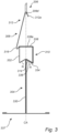
- FIG. 3 Here is conceptually depicted a cross sectional view of a differently shaped profile 304 which is supported by a hanger 206 via a differently shaped suspension element 308.
- the differently shaped profile 304 is similar to the profile 204 of Figs. 2a and 2b .
- the differently shaped suspension element 308 is similar to the suspension element 208 of Figs. 2a and 2b .
- the hanger 206 is of the type described above in conjunction with of Figs. 2a and 2b .
- the profile 304 and the suspension element 308 differences in relation to the profile 204 and the suspension element 208 of Figs. 2a and 2b will mainly be described in order to avoid undue repetition.
- the profile 304 is folded from a metal sheet like the profile 204 of Figs 2a and 2b .
- the bulb 332 of the profile 304 has a flat top portion 338. That is, the bulb 332 of the profile 304 has a flat top surface 338a which is arranged horizontally and extends along a longitudinal extension of the profile 304.
- the bulb 332 comprises a bottom surface 334 having an undercut surface portion 336.
- the undercut surface portion 336 has normal direction N which points downwards and inwards towards the upright web 330 of the profile 304.
- An undercut surface portion 336 is provided on each side of the central axis CA of the profile 304.
- the depicted profile 304 of Fig. 3 comprises a lateral support flange 337 configured to support a ceiling tile.
- the depicted suspension element 308 of Fig. 3 is used for suspending the profile 304.
- the suspension element 308 comprises a clamping section 310 and a suspension section 312.
- the clamping section 310 is configured to clamp the suspension element 308 on the bulb 332 of the profile 308.
- the clamping section 310 may be said to include two principal features like the clamping section 210 of suspension element 208. Those principal features are an engagement element 314 and a clamping element 316.
- the depicted engagement element 314 is of the type described above in conjunction with Figs. 2a and 2b .
- the depicted clamping element 316 is formed as a biased lock feature which is configured to engage a corner or end of the top surface 338a of the bulb 332.
- the depicted clamping element 316 is integrally formed by a portion of the suspension element 308.
- the clamping element 316 is configured to clamp the top portion 338 of the bulb 332 in response to being pushed over the top portion 338 of the bulb 332 while the engagement element 314 engages the undercut surface portion 336 of the bottom surface 334 of the bulb 332.
- the clamping element 316 is configured to be bent back and to snap over the end or corner of the top surface 338a of the top portion 238 of the bulb 232 in response to being pushed over the top portion 338 of the bulb 332 while the engagement element 314 engages the undercut surface portion 336 of the bottom surface 334 of the bulb 332.
- the suspension section 312 of the depicted suspension element 308 includes a hook member 312a which is configured to engage the hook 206d of the hanger 206. Further, when the hook 206d of the hanger 206 engages the hook member 312a the suspension section 312, a longitudinal extension of the hanger 206 coincides with the central axis CA of the profile 304.
- FIG. 4 Here is conceptually depicted a cross sectional view of a differently shaped profile 404 which is supported by a hanger 206 via a differently shaped suspension element 408.
- the differently shaped profile 404 is somewhat similar to the profile 204 of Figs. 2a and 2b .
- the differently shaped suspension element 408 is somewhat similar to the suspension element 208 of Figs. 2a and 2b .
- the hanger 206 is of the type described above in conjunction with of Figs. 2a and 2b .
- the profile 404 and the suspension element 408 differences in relation to the profile 204 and the suspension element 208 of Figs. 2a and 2b will mainly be described in order to avoid undue repetition.
- the profile 404 is formed by an extrusion process.
- the profile 404 is formed by aluminum.
- the bulb 432 of the profile 404 has a generally speaking flat top portion 438. That is, the bulb 432 of the profile 404 has a flat top surface 438a which is arranged horizontally and extends along a longitudinal extension of the profile 404.
- the flat top surface 438a of the top portion 438 of the bulb 432 is provided with a protrusion 438b which extends along a longitudinal extension of the profile 404.
- the bulb 432 comprises a bottom surface 434 having an undercut surface portion 436.
- the bottom surface 434 of the profile 404 is formed as a stepped surface, i.e a set of surfaces which together forms the stepped surface.
- the bottom surface 434 of the profile 404 has an undercut surface portion in the sense that a plane P placed on the bottom surface 434 has normal direction N which points downwards and inwards towards the upright web 430 of the profile 404.
- the undercut surface portion 436 is provided on a single side of the central axis CA of the profile 404.
- the depicted profile 404 of Fig. 4 comprises a lateral support flange 437 configured to support a ceiling tile.
- the depicted suspension element 408 of Fig. 4 is used for suspending the profile 404.
- the suspension element 408 is formed from a fiber reinforced plastic material by an extrusion process.
- the suspension element 408 comprises a clamping section 410 and a suspension section 412.
- the clamping section 410 is configured to clamp the suspension element 408 on the bulb 432 of the profile 408.
- the clamping section 410 may be said to include two principal features like the clamping section 210 of suspension element 208. Those principal features are an engagement element 414 and a clamping element 416.
- the depicted engagement element 414 is generally speaking formed as a hook which is configured to engage with the stepped bottom surface 434 of the bulb 432.
- the engagement element 414 has a flat inside and will thus contact the stepped bottom surface 434 of the bulb 432 at certain discrete locations along the plane P.
- the depicted clamping element 416 is formed as a snap lock feature which is configured to engage the protrusion 438a of the top surface 438a of the bulb 432.
- the depicted clamping element 416 is integrally formed by a portion of the suspension element 408.
- the clamping element 416 is configured to clamp the protrusion 438a of the top portion 438 of the bulb 432 in response to being pushed over the top portion 438 of the bulb 432 while the engagement element 414 engages the undercut surface portion 436 of the bottom surface 434 of the bulb 432.
- the clamping element 416 is configured to be bent up and to snap back over the protrusion 438a of the top surface 438a of the top portion 438 of the bulb 432 in response to being pushed over the top portion 438 of the bulb 432 while the engagement element 414 engages the undercut surface portion 436 of the bottom surface 434 of the bulb 432.
- the suspension section 412 of the depicted suspension element 408 includes a horizontal flange member 412a.
- the flange member 412a includes a recess 412b which is configured to engage the hook 206d of the hanger 206. Further, when the hook 206d of the hanger 206 engages the recess 412b of the suspension section 412, a longitudinal extension of the hanger 206 coincides with the central axis CA of the profile 404.
Landscapes
- Engineering & Computer Science (AREA)
- Architecture (AREA)
- Physics & Mathematics (AREA)
- Electromagnetism (AREA)
- Civil Engineering (AREA)
- Structural Engineering (AREA)
- Clamps And Clips (AREA)
Abstract
Description
- The present invention generally relates to a suspended ceiling system, more specifically to a suspended ceiling system including at least one profile for supporting a ceiling tile, at least one suspension element for suspending the profile and a at least one hanger.
- A suspended ceiling system in a room or in another accommodation may serve a variety of purposes. One purpose of having a suspended ceiling system may be to conceal a structural ceiling. Another purpose may be to provide improved sound absorption and/or sound attenuation in and outside of the room. Another purpose may be to support various equipment installed in the ceiling of a room.
- Moreover, the resulting plenum space located between the suspended ceiling and a structural ceiling of the room may further be utilized to accommodate e.g. wiring, piping, as well as devices related to heating, ventilation and air condition.
- A conventional suspended ceiling system normally comprise profiles or runners used for supporting ceiling tiles. Commonly, the profiles are arranged so as to form a grid of profiles supporting ceiling tiles. The tiles are then arranged in frames formed by the grid of profiles. The tiles are typically adapted for sound absorption. For that reason, tiles made of materials such as stone wool or glass wool are commonly used. However, some suspended ceilings have ceiling tiles made of rigid materials, such as wood, gypsum or metal.
- Such grid of profiles typically includes main runners and often also cross runners. The main runners are normally attached to the structural ceiling of a room via hangers. The hangers are typically made of bars or wires which are attached to the main ceiling and to the main runners such that the main runners become suspended below the main ceiling. The cross runners typically connect perpendicular to the main runners and extend in parallel in order to form frames in which the ceiling tiles typically are arranged.
- Hangers of the above kind are usually designed with suspension hooks at their lower end and constructed for attachment to the main ceiling at their upper end. The suspension hooks of the hangers are commonly designed for hooking into a suspension opening of the runners of the suspended ceiling at hand. The hooking into the suspension opening can present significant problems during installation since the profile generally has to be twisted or moved into various positions other than its intended final position in order to receive a hook through its suspension opening. The problem is generally more pronounced when a plurality of hooks are used for the same profile.
- It has therefore been suggested to suspend the runners by means a suspension element which is fastened to the runners and to which the hangers are connected in turn. Such suspension element is thus a form of an intermediate coupling detail via which a runner is suspended by means of a hanger.
- An example of such a suspension element is described in
European patent application 15165762.4 EP 15165762.4 - The suspension element described in
EP 15165762.4 - A major drawback resides in the fact that the suspension element must be inserted into an opening in the runner in order for the suspension element to be fastened to the runner. This means that the suspension element can only be fastened at certain locations of the runner.
- The fact that the suspension element can only be fastened at certain locations of the runner brings about that the runner can only be suspended in certain longitudinal locations in relation to the hanger. This is clearly a disadvantage since the suspension element introduces limitations both when designing and mounting a suspended celling.
- Further when using the suspension element small adjustments of the position in which the runner is suspended from the hanger becomes troublesome or even impossible. The lack of fine adjustment can result in large aesthetic problems since even the slightest misalignment of the runners of a suspended ceiling are easily visible thereby resulting in an uneasy overall appearance of the suspended ceiling.
- Furthermore, there is a risk that the suspension element come loose from the runner unintentionally since a slightly slandered clamping surface thereof is designed to engage a flat top surface of the runner. This slightly slandered clamping surface can consequently slide off the flat top surface of the runner resulting in that the suspension element come loose. This risk has however been addressed in
EP 15165762.4 - Another disadvantage of the suspension element resides in that the fact that the suspension element extends all way down to the opening provided in the runner. The fact that suspension element extends all way down to the opening of the runner can typically influence the possibility to freely position tiles on the runner since the suspension element will hinder the tiles form being placed in certain positions.
- In view of the above, it is an object of the present invention is to provide an improved suspended ceiling system.
- Another object is to provide such a suspended ceiling system which offers more flexibility in terms of design and installation.
- Another object is to provide such a suspended ceiling system which is easier to install.
- Another object is to provide such a suspended ceiling system which is easier to disassemble.
- Another object is to provide such a suspended ceiling system which is less prone to mechanical failure.
- It is also an object to provide a cost-effective suspended ceiling system.
- To achieve at least one of the above objects and also other objects that will be evident from the following description, a suspended ceiling system having the features defined in
claim 1 is provided according to the present inventive concept. Preferred variations to the inventive concept will be evident from the dependent claims. - More specifically, according to a first aspect, there is provided a suspended ceiling system, the suspended ceiling system comprising: at least one profile for supporting a ceiling tile, the at least one profile comprising a longitudinally extending upright web, and a longitudinal bulb extending along a top end of the upright web, wherein the longitudinal bulb comprises a bottom surface having an undercut surface portion, at least one suspension element for suspending the profile, the suspension element comprising a clamping section and a suspension section, the clamping section being configured to clamp the suspension element on the bulb of the profile, wherein the clamping section comprises an engagement element and a clamping element, wherein the engagement element is configured for engagement with the undercut surface portion of the bottom surface of the bulb, and wherein the clamping element is configured to clamp a top portion of the bulb in response to being pushed over the top portion of the bulb while the engagement element engages the undercut surface portion of the bottom surface of the bulb, and at least one hanger for suspending the at least one profile, wherein each hanger is configured to engage the suspension section of an associated suspension element.
- Hereby an improved suspended ceiling system is provided. The ceiling system includes at least one profile for supporting a ceiling tile, at least one suspension element for suspending the profile and at least one hanger for suspending the at least one profile via the suspension element.
- The at least one profile of the suspended ceiling system is designed for supporting a ceiling tile. For that reason, the profile is typically provided with a lateral support flange for supporting a ceiling tile. A plurality of lateral support flanges may be provided on opposite sides of the profile to support two or more ceiling tiles at different sides of the profile. The lateral support flange or flanges may be arranged at a bottom region or at the bottom of the profile. The lateral support flange or flanges may be made of a metal sheet. The profile is generally made of metal or comprises metal. The profile may however be made of or comprise other materials such plastic.
- The at least one profile comprises a longitudinally extending upright web and a longitudinal bulb. The bulb extends along a top end of the upright web. The longitudinal bulb is typically a portion which is made thicker compared to the upright web. The longitudinal bulb may be folded from a metal sheet. The upright web may be formed of a metal sheet. The longitudinal bulb and the upright web may be folded from a metal sheet.
- The longitudinal bulb comprises a bottom surface having an undercut surface portion. That is, the longitudinal bulb includes at least a portion along its longitudinal extension which has a bottom surface having an undercut surface portion. Such undercut surface portion may be provided at a single side of the longitudinal bulb. Such undercut surface portion may be provided at opposite sides of the longitudinal bulb.
- It should be noted that within the context of this application the term "undercut surface portion" or "undercut surface" may be any type of surface, surface portion, surface set or surface subset which has normal direction which points downwards and inwards towards the upright web. In case of a surface set, such as a stepped surface, a plane placed on the surface set will have normal direction which points downwards and inwards towards the upright web. In other words, the undercut surface portion or undercut surface is generally facing downwards and slanters downwards away from the upright web. In yet other words, the undercut surface portion or undercut surface is so constituted that a height of the surface above a bottom edge of the profile decreases with an increased distance from the upright web. Such decrease may be constant as for a slanted surface, or may be incremental, as for a stepped surface.
- The at least one suspension element is designed for suspending the profile. The suspension element comprises a clamping section and a suspension section.
- The clamping section is configured to clamp the suspension element on the bulb of the profile. For that reason, the clamping section comprises an engagement element and a clamping element.
- The engagement element is configured for engagement with the undercut surface of the bottom surface of the bulb. This means that the engagement element is configured to engage the undercut provided by the undercut surface. Hence, the engagement element is configured to project from the suspension element such that the engagement element grips or to some extent contacts the undercut surface. For this reason, the engagement element may typically include a surface portion which has normal direction which points upwards and outwards from the upright web when the suspension element clamps the profile. The engagement element may include a surface subset such as a stepped surface configured to engage or partially engage the undercut surface of the profile.
- The clamping element is configured to clamp a top portion of the bulb in response to being pushed over the top portion of the bulb while the engagement element engages the undercut surface portion of the bottom surface of the bulb. This means that the clamping element is configured to clamp a top portion of the bulb in response to a push action typically pushing the clamping element over and beyond the top portion of the bulb given that the engagement element engages the undercut surface as discussed above. For this reason, the clamping element may typically be configured to snap over or beyond a feature of the top portion of the bulb, such as a corner, a protrusion or protruding portion.
- The suspension section is configured to engage a hanger of the suspended ceiling system. For that reason, the suspension section is typically provided with an opening, a hook, a loop, a groove, a pair of grooves or similar. The suspension section may be configured for engagement with a particular kind of hanger or may be configured to be able to engage different types of hangers.
- The suspended ceiling system comprises at least one hanger for suspending the at least one profile. Each hanger is configured to engage the suspension section of an associated suspension element. The hanger may include a hook, a loop, a stop element or similar configured to engage the suspension section of an associated suspension element. The hanger may be configured for engagement with a particular kind of suspension section of an associated suspension element or may be configured to be able to engage different types of suspension sections of different types of suspension elements.
- The top portion of the bulb may be formed by a ridge extending in a longitudinal direction of the profile. This is advantageous in that the clamping element of the suspension element may clamp the ridge of the bulb in response to being pushed over the ridge of the bulb. This is further advantageous in that a secure but yet easily releasable connection may be established between the suspension element and the profile by pushing the clamping element over the ridge of the bulb while the engagement element engages the undercut surface portion of the bottom surface of the bulb. The ridge of the bulb may extend along an entire length of the bulb. The ridge of the bulb may extend partially along a length of the bulb. The ridge of the bulb may be incremental. The ridge of the bulb may be formed as a plurality of ridge sections.
- The clamping section may have a shape which is essentially complementary to a shape of a clamped segment of the bulb of the profile, which is advantageous in that the clamping section may securely clamp the bulb of the profile. This is further advantageous in that a tight fit with no or little slack may be achieved between the suspension element and the profile.
- The bottom surface of the bulb may comprise a surface on each side of the upright web, which is advantageous in that an engagement element of a suspension element may engage an undercut surface of the bottom surface of the bulb on either side thereof. In other words, the fact that the bottom surface of the bulb may comprise a surface on each side of the upright web provides for that an undercut surface may be provided on either side of the upright web. This may in turn allow for that a suspension element may be secured to the profile on either side thereof. In other words, one or more suspension elements may be secured to the profile on both sides thereof.
- The suspension element may be formed in a single piece, which is advantageous in that a strong reliable suspension element may be formed in a simple manner. Moreover, it allows for that a suspension element may be formed at a beneficial cost.
- The suspension element may be formed form a metal sheet, which is advantageous in that a strong reliable suspension element may be formed in a simple manner. In practice, a suspension element may be formed by cutting and folding a metal sheet. Moreover, it allows for that a suspension element may be formed at a beneficial cost.
- The suspension element may be formed by an extrusion process, which is advantageous in that a strong reliable suspension element may be formed in a simple manner. In practice, a suspension element may be formed by cutting an extruded profile having a cross section corresponding to a cross section of the suspension element. Moreover, it allows for that a suspension element may be formed using different materials, such as metal and/or plastic. Moreover, it allows for that a fiber reinforced polymer suspension element may be formed. Moreover, it allows for that a suspension element may be formed at a beneficial cost.
- The suspension element may be displaceable along a longitudinal direction of the profile when the clamping section of the suspension element clamps the suspension element on the bulb of the profile, which is advantageous in that a position of the profile may be adjusted in relation to the suspension element. This allows for that the location of a profile may be adjusted in relation to e.g. the structural ceiling of a room even after the profile is suspended. The possibility to displace the suspension element along a longitudinal direction of the profile when the clamping section of the suspension element clamps the suspension element on the bulb of the profile brings about several other advantages. It is for instance possible to attach a desired number of suspension elements to a profile and to later slide the suspension elements into their desired locations. It is for instance possible to attach a suspension element to a profile and to later slide the suspension element into its desired location.
- The engagement element may be arranged on a single side of the upright web of the profile when the clamping section of the suspension element clamps the suspension element on the bulb of the profile, which is advantageous in that another, opposite, side of the upright web may be left unaffected when the suspension element is attached to the profile. This brings about that the suspension element is less prone to hinder and negatively influence how ceiling tiles may be supported by the profile.
- The clamping element may comprise a crest extending in a longitudinal direction of the profile and coinciding with a vertical plane defined by the upright web when the clamping section of the suspension element clamps the suspension element on the bulb of the profile, which is advantageous in that the crest may engage a top portion of the bulb. The crest may form part of the clamping element and may thus clamp a feature of the bulb. The crest may clamp a ridge of the bulb. The crest may clamp a top portion of the of the bulb formed by a ridge. A crest is combination with a ridge may form a secure and yet easily releasable connection between the suspension element and the profile. A crest is combination with a ridge may form a secure and yet easily releasable snap fit connection between the suspension element and the profile.
- The suspension section of the at least one suspension element may be configured to engage a hook member of the at least one hanger, which is advantageous in that the suspension element and any profile attached thereto may be suspended in a simple any yet reliable manner. The suspension section of the at least one suspension element may include various features configured to engage a hook member of the at least one hanger. The suspension section of the at least one suspension element may include a hook, a loop, hole, an opening, a channel, a cut out, a pair of cut outs or similar for reception of a hook member of the at least one hanger.
- The profile may further comprise a lateral support flange configured to support the ceiling tile and extending along a bottom end of the upright web, which is advantageous in that the ceiling tile may be supported in a simple and yet reliable manner.
- The lateral support flange may comprise a surface on each side of the upright web, which is advantageous in that the profile may support ceiling tiles on either side thereof.
- The above, as well as additional objects, features and advantages of the present invention, will be better understood through the following illustrative and non-limiting detailed description of preferred variants of the present inventive concept, with reference to the appended drawings, where the same reference numerals will be used for similar elements, wherein:
-
Fig. 1 conceptually illustrates a suspended ceiling system including a grid of profiles and a plurality of suspension elements and associated hangers. -
Fig. 2a conceptually illustrates a cross sectional view of a profile which is supported by a hanger via a suspension element. -
Fig. 2b conceptually illustrates the profile which is supported by the hanger via the suspension element ofFig. 2a . -
Fig. 3 conceptually illustrates a cross sectional view of a differently shaped profile which is supported by a hanger via a differently shaped suspension element. -
Fig. 4 conceptually illustrates a cross sectional view of a yet differently shaped profile which is supported by a hanger via a yet differently shaped suspension element. - The present inventive concept will now be described more fully hereinafter with reference to the accompanying drawings, in which preferred variants of the inventive concept are shown. This inventive concept may, however, be embodied in many different forms and should not be construed as limited to the variants set forth herein; rather, these variants are provided for thoroughness and completeness, and fully convey the scope of the inventive concept to the skilled person. Like reference numerals refer to like elements throughout the description.
- Initially a suspended
ceiling system 100 will be described with reference toFig. 1. Fig. 1 is a schematic perspective view conceptually depicting a suspendedceiling system 100. Theceiling system 100 comprises a grid ofprofiles 102. The grid ofprofiles 102 comprises a plurality ofprofiles 103, some in form ofmain runners 104a-c extending side by side. For reasons of simplicity there are threemain runners 104a-c illustrated inFig. 1 . Theceiling system 100 may include any number of profiles in form ofmain runners 104a-c extending side by side. Theceiling system 100 may thus be used to form a suspended ceiling of an arbitrary size. - In the depicted
ceiling system 100, the grid ofprofiles 102 further includesprofiles 103 in form ofcross runners 105. Thecross runners 105 are optional and may or may not be present in the grid ofprofiles 102. The depictedcross runners 105 are interconnecting the plurality ofmain runners 104a-c extending side by side, i.e. thecross runners 105 are attached to the respectivemain runners 104a-c. The length of thecross runners 105 is typically about the distance between two adjacent main runners. However, the cross runners may be arranged an oblique angle with respect to themain runners 104a-c. In this case the length of thecross runners 105 are typically adapted so as to interconnect adjacent main runners irrespective of the oblique angle. - The depicted
ceiling system 100 also includes a plurality ofceiling tiles 120 arranged in the grid ofprofiles 102. Eightceiling tiles 120 are depicted for reasons of simplicity although any number ofceiling tiles 120 may be used with theceiling system 100. - Further, the depicted
ceiling system 100 also includes twelvehangers 106. Thehangers 106 are connected to themain runners 104a-c of theprofiles 103 of the grid ofprofiles 102 via arespective suspension element 108. Hence, each hanger is connected to one of themain runners 104a-c. More specifically, each hanger is connected to asuspension element 108 which in turn is connected to one of themain runners 104a-c. It is to be noted thatsuspension elements 108 may be connected to thecross runners 105 of theprofiles 103. - Each
hanger 106 is connected to astructural ceiling 110 shown in phantom inFig. 1 . - The design of the
profiles 103, thesuspension elements 108 and thehangers 106 will be elaborated upon below with reference toFigs. 2a and2b . -
Figs. 2a and2b are detail views of aprofile 204 with ahanger 206 attached thereto via asuspension element 208. Theprofile 204 corresponds to a profile ofFig. 1 such as e.g. theprofile 104a. Correspondingly, thehanger 206 corresponds to ahanger 106 ofFig. 1 and thesuspension element 208 corresponds to asuspension element 108 ofFig. 1 . The profile supports aceiling tile 220, such asceiling tile 120 ofFig. 1 . Theceiling tile 220 ofFig. 2a is shown in phantom to not obscure details of theprofile 204. - The
profile 204 comprises a longitudinally extendingupright web 230. Theprofile 204 further comprises alongitudinal bulb 232 extending along a top end of theupright web 230. Thelongitudinal bulb 232 comprises abottom surface 234 having an undercutsurface portion 236. The depictedprofile 204 ofFigs. 2a and2b comprises alateral support flange 237 configured to support theceiling tile 220. Thelateral support flange 237 extends along a bottom end of theupright web 230. In the depictedprofile 204 ofFigs. 2a and2b thelateral support flange 237 comprises asurface upright web 230. InFigs. 2a and2b aceiling tile 220 is supported bysurface 237a of thesupport flange 237. - The depicted
profile 204 ofFigs. 2a and2b is folded from a metal sheet as best seen inFig. 2a . However, the profile may be formed using any suitable technique and material to advantage. - As can be seen in
Figs. 2a and2b , the undercutsurface portion 236 has normal direction N which points downwards and inwards towards theupright web 230 of theprofile 204. That is, the lower portion of thebulb 232 forms what commonly is referred to as an overhang. The depicted undercutsurface portion 236 is hence located on the overhang on an underside thereof. The depicted undercutsurface portion 236 is thus facing downwards and slanters downwards away from theupright web 230. InFigs. 2a and2b , the undercutsurface portion 236 extends along the longitudinal extension of thebulb 232. However, the undercutsurface portion 236 may be incremental and extend along a portion of thebulb 232. A plurality of undercutsurface portions 236 may be present along thebulb 232. Undercutsurface portions 236 may be located on either side of thebulb 232. That is, thebottom surface 234 of thebulb 232 may comprise a surface on each side of theupright web 230, as depicted inFigs. 2a and2b . - The depicted
suspension element 208 ofFigs. 2a and2b is used for suspending theprofile 204. Thesuspension element 208 comprises aclamping section 210 and asuspension section 212. Theclamping section 210 is configured to clamp thesuspension element 208 on thebulb 232 of theprofile 208. Theclamping section 210 may be said to include two principal features, namely anengagement element 214 and aclamping element 216. - The depicted
engagement element 214 is formed as what may be regarded a hook. Theengagement element 214 is configured for engagement with the undercutsurface 236 of thebottom surface 234 of thebulb 232. For that reason, the depictedengagement element 214 is formed such that it follows the undercutsurface 236 of thebottom surface 234 of thebulb 232 when thesuspension element 208 is attached to theprofile 208. - As can be seen in
Figs. 2a and2b , theclamping section 210 of thesuspension element 208 is mainly extending down on one side of a central axis CA of theprofile 204. This means that a lower portion of theclamping section 210 of thesuspension element 208 which is provided with theengagement element 214 is located on one side of the central axis CA. In other words, theengagement element 214 is arranged on a single side of theupright web 230 of theprofile 204 when theclamping section 210 of thesuspension element 208 clamps thesuspension element 208 on thebulb 232 of theprofile 204. - The depicted
clamping element 216 is formed as a biased lock feature which is configured to engage thebulb 232. The clampingelement 216 comprises acrest 216a which extends in a longitudinal direction of theprofile 204. Thecrest 216a coincides with a vertical plane defined by theupright web 230 when theclamping section 210 of thesuspension element 208 clamps thesuspension element 208 on thebulb 232 of theprofile 204. In other words, thecrest 216a coincides with the central axis CA of theprofile 204. - The depicted
clamping element 216 is integrally formed by a portion of thesuspension element 208. The clampingelement 216 is configured to clamp atop portion 238 of thebulb 232 in response to being pushed over thetop portion 238 of thebulb 232 while theengagement element 214 engages the undercutsurface portion 236 of thebottom surface 234 of thebulb 232. In other words, the clampingelement 216 is configured to be bent back and to snap over thetop portion 238 of thebulb 232 in response to being pushed over thetop portion 238 of thebulb 232 while theengagement element 214 engages the undercutsurface portion 236 of thebottom surface 234 of thebulb 232. InFigs. 2a and2b , thetop portion 238 of thebulb 232 is formed by aridge 238a extending in a longitudinal direction of theprofile 204. - The
suspension element 208 is generally configured to be attached to theprofile 204, by first engaging theengagement element 214 with the undercutsurface portion 236 and thereafter pushing theclamping element 216 past thetop portion 238 of thebulb 232 such that it is bent back and thereafter snaps over thetop portion 238 of thebulb 232. Other strategies of attaching thesuspension element 208 to theprofile 204 may however be used to advantage. - As can be seen in
Figs. 2a and2b theclamping section 210 of thesuspension element 208 has a shape which is essentially complementary to a shape of a clamped segment of thebulb 232 of theprofile 204. However, it should be noted that different designs where theclamping section 210 of thesuspension element 208 has a shape which is not complementary to a shape of a clamped segment of thebulb 232 of theprofile 204 may be used to advantage. Thesuspension element 208 may for instance engage with theprofile 204 at certain discrete points and thus not follow a general contour thereof. - As discussed above, in the depicted
suspension element 208 ofFigs. 2a and2b theclamping section 210 of thesuspension element 208 has a shape which is essentially complementary to a shape of a clamped segment of thebulb 232 of theprofile 204. This brings about that thesuspension element 208 is displaceable along a longitudinal direction of theprofile 204 when theclamping section 210 of thesuspension element 208 clamps thesuspension element 208 on thebulb 232 of theprofile 204. The fact that thesuspension element 208 is displaceable along a longitudinal direction of theprofile 204 is indicated by two arrows pointing in opposite directions inFig. 2b . Further, the fact that thesuspension element 208 is displaceable along a longitudinal direction of theprofile 204 brings about that a location of theprofile 204 in relation to thehanger 206 may be adjusted by simply sliding thesuspension element 208 along theprofile 204. - The depicted
suspension element 208 ofFigs. 2a and2b is formed in a single piece. Thesuspension element 208 may however be assembled form a plurality of parts to advantage. Thesuspension element 208 may be assembled form two parts to advantage. - The depicted
suspension element 208 ofFigs. 2a and2b is formed form a metal sheet. The depictedsuspension element 208 is consequently formed by cutting and folding a metal sheet so as to form thesuspension element 208. - As an alternative, the
suspension element 208 may be formed by a plastic material. Thesuspension element 208 may be formed by a fiber reinforced plastic material. Thesuspension element 208 may include metal and plastic. - As an alternative, the
suspension element 208 may be formed by an extrusion process.Such suspension element 208 formed by an extrusion process may be formed by metal.Such suspension element 208 formed by an extrusion process may be formed by a plastic material.Such suspension element 208 formed by an extrusion process may be formed by a fiber reinforced plastic material. - The depicted
hanger 206 ofFigs. 2a and2b is used for suspending theprofile 204. Thehanger 206 is configured to engage thesuspension section 212 of thesuspension element 208. The depictedhanger 206 is formed by a pair ofrods adjustment element 206c. Thelower rod 206a includes ahook member 206d orhook 206d at its lower end. Thehook 206d is formed by bending therod 206a. Thehook 206d is configured to engage thesuspension section 212 of thesuspension element 208. Thehook 206d is integrally formed with therod 206a. Thehook 206d may however be formed separately from therod 206a. - A length of the depicted
hanger 206 may be shortened by sliding therods adjustment element 206c. Correspondingly, a length of the depictedhanger 206 may be longed by compressing the generallyresilient adjustment element 206c and sliding therods adjustment element 206c. - The
hanger 206 may be of any suitable kind. Thehanger 206 may be made in one piece. Thehanger 206 may be of a fixed length. Thehanger 206 may include a wire and a hook. Thehanger 206 may be made of a wire. Thehanger 206 may include a loop instead of a hook. Thehanger 206 may include a loop and a hook. - As described above, the depicted
suspension element 208 comprises aclamping section 210 and asuspension section 212. Thesuspension section 212 of the depictedsuspension element 208 includes a horizontally arrangedflange 2b:1. Theflange 2b:1 is formed with two opposite recesses configured to receive thehook 206d of thehanger 206. When thehook 206d engages the two recesses offlange 2b:1 of thesuspension section 212, thehook 206d is prevented or counteracted from sliding off thesuspension section 212. - Further, when the
hook 206d of thehanger 206 engages the two recesses offlange 2b:1 of thesuspension section 212, a longitudinal extension of thelower rod 206a of thehanger 206 coincides with the central axis CA of theprofile 204. - The
suspension section 212 of thesuspension element 208 may be formed using different designs to advantage. InFig. 2b four additional different designs of thesuspension section 212 of thesuspension element 208 are shown. More specifically, four additional different designs of the horizontally arrangedflange 2b:1 of thesuspension section 212 are show. The additional different designs of the horizontally arrangedflange 2b:1 are shown to the left inFig. 2b . The flanges formed according to the additional different designs are denoted 2b:2, 2b:3, 2b:4 and 2b:5 respectively.Flanges 2b:2, 2b:3, 2b:4 and 2b:5 are similar toflange 2b:1. However, the way therespective flanges 2b:2, 2b:3, 2b:4 and 2b:5 interact with thehook 206d of thehanger 206 are different as compared to theflange 2b:1. Theflange 2b:2 is provided with a hole configured to receive thehook 206d of thehanger 206. Theflange 2b:3 is provided with a single recess configured to receive thehook 206d of thehanger 206. Theflange 2b:4 is provided with a loop configured to receive thehook 206d of thehanger 206. Theflange 2b:5 is provided with a hook configured to receive thehook 206d of thehanger 206. Like theflange 2b:1, theflanges 2b:2, 2b:3, 2b:4 and 2b:5 are all designed such that, when thehook 206d engages the features of aflange 2b:2, 2b:3, 2b:4, 2b:5 thehook 206d is prevented or counteracted from sliding off thesuspension section 212. Moreover, when thehook 206d of thehanger 206 engages any one of theflanges 2b:2, 2b:3, 2b:4, 2b:5 of thesuspension section 212, the longitudinal extension of thelower rod 206a of thehanger 206 coincides with the central axis CA of theprofile 204. - Now referring to
Fig. 3 . Here is conceptually depicted a cross sectional view of a differently shapedprofile 304 which is supported by ahanger 206 via a differently shapedsuspension element 308. - As can be seen in
Fig. 3 , the differently shapedprofile 304 is similar to theprofile 204 ofFigs. 2a and2b . Correspondingly, the differently shapedsuspension element 308 is similar to thesuspension element 208 ofFigs. 2a and2b . Thehanger 206 is of the type described above in conjunction with ofFigs. 2a and2b . In the following, when describing theprofile 304 and thesuspension element 308 differences in relation to theprofile 204 and thesuspension element 208 ofFigs. 2a and2b will mainly be described in order to avoid undue repetition. - The
profile 304 is folded from a metal sheet like theprofile 204 ofFigs 2a and2b . However, in theprofile 304 thebulb 332 of theprofile 304 has a flattop portion 338. That is, thebulb 332 of theprofile 304 has a flattop surface 338a which is arranged horizontally and extends along a longitudinal extension of theprofile 304. - The
bulb 332 comprises abottom surface 334 having an undercutsurface portion 336. The undercutsurface portion 336 has normal direction N which points downwards and inwards towards theupright web 330 of theprofile 304. An undercutsurface portion 336 is provided on each side of the central axis CA of theprofile 304. - The depicted
profile 304 ofFig. 3 comprises alateral support flange 337 configured to support a ceiling tile. - The depicted
suspension element 308 ofFig. 3 is used for suspending theprofile 304. - The
suspension element 308 comprises aclamping section 310 and asuspension section 312. Theclamping section 310 is configured to clamp thesuspension element 308 on thebulb 332 of theprofile 308. Theclamping section 310 may be said to include two principal features like theclamping section 210 ofsuspension element 208. Those principal features are anengagement element 314 and aclamping element 316. The depictedengagement element 314 is of the type described above in conjunction withFigs. 2a and2b . - The depicted
clamping element 316 is formed as a biased lock feature which is configured to engage a corner or end of thetop surface 338a of thebulb 332. The depictedclamping element 316 is integrally formed by a portion of thesuspension element 308. The clampingelement 316 is configured to clamp thetop portion 338 of thebulb 332 in response to being pushed over thetop portion 338 of thebulb 332 while theengagement element 314 engages the undercutsurface portion 336 of thebottom surface 334 of thebulb 332. In other words, the clampingelement 316 is configured to be bent back and to snap over the end or corner of thetop surface 338a of thetop portion 238 of thebulb 232 in response to being pushed over thetop portion 338 of thebulb 332 while theengagement element 314 engages the undercutsurface portion 336 of thebottom surface 334 of thebulb 332. - The
suspension section 312 of the depictedsuspension element 308 includes ahook member 312a which is configured to engage thehook 206d of thehanger 206. Further, when thehook 206d of thehanger 206 engages thehook member 312a thesuspension section 312, a longitudinal extension of thehanger 206 coincides with the central axis CA of theprofile 304. - Now referring to
Fig. 4 . Here is conceptually depicted a cross sectional view of a differently shapedprofile 404 which is supported by ahanger 206 via a differently shapedsuspension element 408. - As can be seen in
Fig. 4 , the differently shapedprofile 404 is somewhat similar to theprofile 204 ofFigs. 2a and2b . Correspondingly, the differently shapedsuspension element 408 is somewhat similar to thesuspension element 208 ofFigs. 2a and2b . Thehanger 206 is of the type described above in conjunction with ofFigs. 2a and2b . In the following, when describing theprofile 404 and thesuspension element 408 differences in relation to theprofile 204 and thesuspension element 208 ofFigs. 2a and2b will mainly be described in order to avoid undue repetition. - The
profile 404 is formed by an extrusion process. Theprofile 404 is formed by aluminum. In theprofile 404 thebulb 432 of theprofile 404 has a generally speaking flattop portion 438. That is, thebulb 432 of theprofile 404 has a flattop surface 438a which is arranged horizontally and extends along a longitudinal extension of theprofile 404. The flattop surface 438a of thetop portion 438 of thebulb 432 is provided with aprotrusion 438b which extends along a longitudinal extension of theprofile 404. - The
bulb 432 comprises abottom surface 434 having an undercutsurface portion 436. Thebottom surface 434 of theprofile 404 is formed as a stepped surface, i.e a set of surfaces which together forms the stepped surface. Thebottom surface 434 of theprofile 404 has an undercut surface portion in the sense that a plane P placed on thebottom surface 434 has normal direction N which points downwards and inwards towards theupright web 430 of theprofile 404. The undercutsurface portion 436 is provided on a single side of the central axis CA of theprofile 404. - The depicted
profile 404 ofFig. 4 comprises alateral support flange 437 configured to support a ceiling tile. - The depicted
suspension element 408 ofFig. 4 is used for suspending theprofile 404. Thesuspension element 408 is formed from a fiber reinforced plastic material by an extrusion process. - The
suspension element 408 comprises aclamping section 410 and asuspension section 412. Theclamping section 410 is configured to clamp thesuspension element 408 on thebulb 432 of theprofile 408. Theclamping section 410 may be said to include two principal features like theclamping section 210 ofsuspension element 208. Those principal features are anengagement element 414 and aclamping element 416. The depictedengagement element 414 is generally speaking formed as a hook which is configured to engage with the steppedbottom surface 434 of thebulb 432. Theengagement element 414 has a flat inside and will thus contact the steppedbottom surface 434 of thebulb 432 at certain discrete locations along the plane P. - The depicted
clamping element 416 is formed as a snap lock feature which is configured to engage theprotrusion 438a of thetop surface 438a of thebulb 432. The depictedclamping element 416 is integrally formed by a portion of thesuspension element 408. The clampingelement 416 is configured to clamp theprotrusion 438a of thetop portion 438 of thebulb 432 in response to being pushed over thetop portion 438 of thebulb 432 while theengagement element 414 engages the undercutsurface portion 436 of thebottom surface 434 of thebulb 432. In other words, the clampingelement 416 is configured to be bent up and to snap back over theprotrusion 438a of thetop surface 438a of thetop portion 438 of thebulb 432 in response to being pushed over thetop portion 438 of thebulb 432 while theengagement element 414 engages the undercutsurface portion 436 of thebottom surface 434 of thebulb 432. - The
suspension section 412 of the depictedsuspension element 408 includes ahorizontal flange member 412a. Theflange member 412a includes arecess 412b which is configured to engage thehook 206d of thehanger 206. Further, when thehook 206d of thehanger 206 engages therecess 412b of thesuspension section 412, a longitudinal extension of thehanger 206 coincides with the central axis CA of theprofile 404. - It will be appreciated that the present inventive concept is not limited to the variants shown. Several modifications and variations are thus conceivable within the scope of the invention which thus is exclusively defined by the appended claims.
Claims (13)
- A suspended ceiling system (100), the suspended ceiling system (100) comprising:at least one profile (104a-c, 204, 304, 404) for supporting a ceiling tile (120), the at least one profile (104a-c, 204, 304, 404) comprising a longitudinally extending upright web (230, 330, 430), and a longitudinal bulb (232, 332, 432) extending along a top end of the upright web (230, 330, 430), wherein the longitudinal bulb (232, 332, 432) comprises a bottom surface (234, 334, 434) having an undercut surface portion (236, 336, 436),at least one suspension element (108, 208, 308, 408) for suspending the profile (104a-c, 204, 304, 404) the suspension element (208, 308, 408) comprising a clamping section (210, 310, 410) and a suspension section (212, 312, 412), the clamping section (210, 310, 410) being configured to clamp the suspension element (208, 308, 408) on the bulb (232, 332, 432) of the profile (104a-c, 204, 304, 404) wherein the clamping section (210, 310, 410) comprises an engagement element (214, 314, 414) and a clamping element (216, 316, 416), wherein the engagement element (216, 316, 416) is configured for engagement with the undercut surface portion (236, 336, 436) of the bottom surface (234, 334, 434) of the bulb (232, 332, 432), and wherein the clamping element (216, 316, 416) is configured to clamp a top portion (238, 338, 438) of the bulb (232, 332, 432) in response to being pushed over the top portion (238, 338, 438) of the bulb (232, 332, 432) while the engagement element (214, 314, 414) engages the undercut surface portion (236, 336, 436) of the bottom surface (234, 334, 434) of the bulb (232, 332, 432), andat least one hanger (106, 206) for suspending the at least one profile (104a-c, 204, 304, 404), wherein each hanger (206) is configured to engage the suspension section (212, 312, 412) of an associated suspension element (108, 208, 308, 408).
- The suspended ceiling system (100), according to claim 1, wherein the top portion (238, 338, 438) of the bulb (232, 332, 432) is formed by a ridge (238a) extending in a longitudinal direction of the profile (104a-c, 204, 304, 404).
- The suspended ceiling system (100), according to claim 1 or 2, wherein the clamping section (210, 310, 410) has a shape which is essentially complementary to a shape of a clamped segment of the bulb (232, 332, 432) of the profile (104a-c, 204, 304, 404).
- The suspended ceiling system (100), according to any one of the preceding claims wherein the bottom surface (234, 334, 434) of the bulb (232, 332, 432) comprises a surface on each side of the upright web (230, 330, 430).
- The suspended ceiling system (100), according to any one of the preceding claims wherein the suspension element (108, 208, 308, 408) is formed in a single piece.
- The suspended ceiling system (100), according to any one of the preceding claims wherein the suspension element (108, 208, 308) is formed form a metal sheet.
- The suspended ceiling system (100), according to any one of the preceding claims wherein the suspension element (108, 208, 308, 408) is formed by an extrusion process.
- The suspended ceiling system (100), according to any one of the preceding claims wherein the suspension element (108, 208, 308, 408) is displaceable along a longitudinal direction of the profile (104a-c, 204, 304, 404) when the clamping section (210, 310, 410) of the suspension element (208, 308, 408) clamps the suspension element (108, 208, 308, 408) on the bulb (232, 332, 432) of the profile (104a-c, 204, 304, 404).
- The suspended ceiling system (100), according to any one of the preceding claims wherein the engagement element (214, 314, 414) is arranged on a single side of the upright web (230, 330, 430) of the profile (104a-c, 204, 304, 404) when the clamping section (210, 310, 410) of the suspension element (108, 208, 308, 408) clamps the suspension element (108, 208, 308, 408) on the bulb (232, 332, 432) of the profile (104a-c, 204, 304, 404).
- The suspended ceiling system (100), according to any one of the preceding claims wherein the clamping element (216, 316, 416) comprises a crest (216a) extending in a longitudinal direction of the profile (104a-c, 204, 304, 404) and coinciding with a vertical plane defined by the upright web (230, 330, 430) when the clamping section (210, 310, 410) of the suspension element (108, 208, 308, 408) clamps the suspension element (108, 208, 308, 408) on the bulb (232, 332, 432) of the profile (104a-c, 204, 304, 404).
- The suspended ceiling system (100), according to any one of the preceding claims wherein the suspension section (212, 312, 412) of the at least one suspension element (108, 208, 308, 408) is configured to engage a hook member (206d) of the at least one hanger (206).
- The suspended ceiling system (100), according to any one of the preceding claims wherein the profile (104a-c, 204, 304, 404) further comprises a lateral support flange (237, 337, 437) configured to support the ceiling tile (220) and extending along a bottom end of the upright web (230, 330, 430).
- The suspended ceiling system (100), according to preceding claim 12 wherein the lateral support flange (237, 337, 437) comprises a surface (237a, 237b) on each side of the upright web (230, 330, 430).
Priority Applications (4)
| Application Number | Priority Date | Filing Date | Title |
|---|---|---|---|
| EP22176746.0A EP4286619B1 (en) | 2022-06-01 | 2022-06-01 | Suspended ceiling system |
| CA3250336A CA3250336A1 (en) | 2022-06-01 | 2023-05-17 | Suspended ceiling system |
| PCT/EP2023/063219 WO2023232470A1 (en) | 2022-06-01 | 2023-05-17 | Suspended ceiling system |
| US18/861,871 US20250154762A1 (en) | 2022-06-01 | 2023-05-17 | Suspended ceiling system |
Applications Claiming Priority (1)
| Application Number | Priority Date | Filing Date | Title |
|---|---|---|---|
| EP22176746.0A EP4286619B1 (en) | 2022-06-01 | 2022-06-01 | Suspended ceiling system |
Publications (2)
| Publication Number | Publication Date |
|---|---|
| EP4286619A1 true EP4286619A1 (en) | 2023-12-06 |
| EP4286619B1 EP4286619B1 (en) | 2026-08-05 |
Family
ID=81878000
Family Applications (1)
| Application Number | Title | Priority Date | Filing Date |
|---|---|---|---|
| EP22176746.0A Active EP4286619B1 (en) | 2022-06-01 | 2022-06-01 | Suspended ceiling system |
Country Status (4)
| Country | Link |
|---|---|
| US (1) | US20250154762A1 (en) |
| EP (1) | EP4286619B1 (en) |
| CA (1) | CA3250336A1 (en) |
| WO (1) | WO2023232470A1 (en) |
Citations (3)
| Publication number | Priority date | Publication date | Assignee | Title |
|---|---|---|---|---|
| US4723749A (en) * | 1986-05-19 | 1988-02-09 | Erico International Corporation | Channel clip |
| US20180100527A1 (en) * | 2016-10-12 | 2018-04-12 | Flexhead Industries, Inc. | Snap to grid bracket for a sprinkler support assembly |
| EP3839164A1 (en) * | 2019-12-16 | 2021-06-23 | Saint-Gobain Ecophon AB | Suspended ceiling system and method for installing thereof |
Family Cites Families (2)
| Publication number | Priority date | Publication date | Assignee | Title |
|---|---|---|---|---|
| US3816880A (en) * | 1972-12-04 | 1974-06-18 | Prudential Lighting Corp | Multiple detent retaining clip |
| US6327758B1 (en) * | 1999-11-01 | 2001-12-11 | Juno Manufacturing, Inc. | Resilient unitary lighting clip |
-
2022
- 2022-06-01 EP EP22176746.0A patent/EP4286619B1/en active Active
-
2023
- 2023-05-17 US US18/861,871 patent/US20250154762A1/en active Pending
- 2023-05-17 CA CA3250336A patent/CA3250336A1/en active Pending
- 2023-05-17 WO PCT/EP2023/063219 patent/WO2023232470A1/en not_active Ceased
Patent Citations (3)
| Publication number | Priority date | Publication date | Assignee | Title |
|---|---|---|---|---|
| US4723749A (en) * | 1986-05-19 | 1988-02-09 | Erico International Corporation | Channel clip |
| US20180100527A1 (en) * | 2016-10-12 | 2018-04-12 | Flexhead Industries, Inc. | Snap to grid bracket for a sprinkler support assembly |
| EP3839164A1 (en) * | 2019-12-16 | 2021-06-23 | Saint-Gobain Ecophon AB | Suspended ceiling system and method for installing thereof |
Also Published As
| Publication number | Publication date |
|---|---|
| EP4286619B1 (en) | 2026-08-05 |
| CA3250336A1 (en) | 2023-12-07 |
| WO2023232470A1 (en) | 2023-12-07 |
| US20250154762A1 (en) | 2025-05-15 |
Similar Documents
| Publication | Publication Date | Title |
|---|---|---|
| US11098481B2 (en) | Canopy system and group suspension system therefore | |
| US11447945B2 (en) | Panel system and support member for use with the same | |
| US6205733B1 (en) | Direct mount ceiling panel grid system | |
| AU2010213961B2 (en) | Mounting clip | |
| US20020060280A1 (en) | Fixture suspension bracket assembly | |
| US12320116B2 (en) | Ceiling system | |
| US11261601B2 (en) | Cross runner connector and cross runner connector arrangement for a suspended ceiling system | |
| EP4469642B1 (en) | A suspension system for an acoustic ceiling island platform and an acoustic ceiling island platform | |
| EP3839164A1 (en) | Suspended ceiling system and method for installing thereof | |
| US20250154762A1 (en) | Suspended ceiling system | |
| US5433662A (en) | Air bar | |
| CN111502169B (en) | Wallboard connecting piece and whole bathroom | |
| KR102807781B1 (en) | Fixing bracket for ceiling panel | |
| CZ294841B6 (en) | Profiled rail and connecting element for supporting device | |
| WO2025215205A1 (en) | Cross runner and suspended ceiling system |
Legal Events
| Date | Code | Title | Description |
|---|---|---|---|
| PUAI | Public reference made under article 153(3) epc to a published international application that has entered the european phase |
Free format text: ORIGINAL CODE: 0009012 |
|
| STAA | Information on the status of an ep patent application or granted ep patent |
Free format text: STATUS: THE APPLICATION HAS BEEN PUBLISHED |
|
| AK | Designated contracting states |
Kind code of ref document: A1 Designated state(s): AL AT BE BG CH CY CZ DE DK EE ES FI FR GB GR HR HU IE IS IT LI LT LU LV MC MK MT NL NO PL PT RO RS SE SI SK SM TR |
|
| STAA | Information on the status of an ep patent application or granted ep patent |
Free format text: STATUS: REQUEST FOR EXAMINATION WAS MADE |
|
| 17P | Request for examination filed |
Effective date: 20240521 |
|
| RBV | Designated contracting states (corrected) |
Designated state(s): AL AT BE BG CH CY CZ DE DK EE ES FI FR GB GR HR HU IE IS IT LI LT LU LV MC MK MT NL NO PL PT RO RS SE SI SK SM TR |
|
| GRAP | Despatch of communication of intention to grant a patent |
Free format text: ORIGINAL CODE: EPIDOSNIGR1 |
|
| STAA | Information on the status of an ep patent application or granted ep patent |
Free format text: STATUS: GRANT OF PATENT IS INTENDED |
|
| INTG | Intention to grant announced |
Effective date: 20260126 |
|
| GRAS | Grant fee paid |
Free format text: ORIGINAL CODE: EPIDOSNIGR3 |
|
| GRAA | (expected) grant |
Free format text: ORIGINAL CODE: 0009210 |
|
| STAA | Information on the status of an ep patent application or granted ep patent |
Free format text: STATUS: THE PATENT HAS BEEN GRANTED |
|
| AK | Designated contracting states |
Kind code of ref document: B1 Designated state(s): AL AT BE BG CH CY CZ DE DK EE ES FI FR GB GR HR HU IE IS IT LI LT LU LV MC MK MT NL NO PL PT RO RS SE SI SK SM TR |
|
| REG | Reference to a national code |
Ref country code: CH Ref legal event code: F10 Free format text: ST27 STATUS EVENT CODE: U-0-0-F10-F00 (AS PROVIDED BY THE NATIONAL OFFICE) Effective date: 20260805 |