EP4286312A1 - Yarn joining device - Google Patents
Yarn joining device Download PDFInfo
- Publication number
- EP4286312A1 EP4286312A1 EP23175574.5A EP23175574A EP4286312A1 EP 4286312 A1 EP4286312 A1 EP 4286312A1 EP 23175574 A EP23175574 A EP 23175574A EP 4286312 A1 EP4286312 A1 EP 4286312A1
- Authority
- EP
- European Patent Office
- Prior art keywords
- yarn joining
- yarn
- nozzle
- metal
- space
- Prior art date
- Legal status (The legal status is an assumption and is not a legal conclusion. Google has not performed a legal analysis and makes no representation as to the accuracy of the status listed.)
- Pending
Links
Images




Classifications
-
- B—PERFORMING OPERATIONS; TRANSPORTING
- B65—CONVEYING; PACKING; STORING; HANDLING THIN OR FILAMENTARY MATERIAL
- B65H—HANDLING THIN OR FILAMENTARY MATERIAL, e.g. SHEETS, WEBS, CABLES
- B65H69/00—Methods of, or devices for, interconnecting successive lengths of material; Knot-tying devices ;Control of the correct working of the interconnecting device
- B65H69/02—Methods of, or devices for, interconnecting successive lengths of material; Knot-tying devices ;Control of the correct working of the interconnecting device by means of adhesives
-
- B—PERFORMING OPERATIONS; TRANSPORTING
- B65—CONVEYING; PACKING; STORING; HANDLING THIN OR FILAMENTARY MATERIAL
- B65H—HANDLING THIN OR FILAMENTARY MATERIAL, e.g. SHEETS, WEBS, CABLES
- B65H69/00—Methods of, or devices for, interconnecting successive lengths of material; Knot-tying devices ;Control of the correct working of the interconnecting device
- B65H69/06—Methods of, or devices for, interconnecting successive lengths of material; Knot-tying devices ;Control of the correct working of the interconnecting device by splicing
- B65H69/061—Methods of, or devices for, interconnecting successive lengths of material; Knot-tying devices ;Control of the correct working of the interconnecting device by splicing using pneumatic means
-
- B—PERFORMING OPERATIONS; TRANSPORTING
- B65—CONVEYING; PACKING; STORING; HANDLING THIN OR FILAMENTARY MATERIAL
- B65H—HANDLING THIN OR FILAMENTARY MATERIAL, e.g. SHEETS, WEBS, CABLES
- B65H2701/00—Handled material; Storage means
- B65H2701/30—Handled filamentary material
- B65H2701/31—Textiles threads or artificial strands of filaments
Definitions
- the present disclosure relates to a yarn joining device.
- a yarn joining unit (a yarn joining device) having a yarn joining chamber, which is a space in which yarn joining is performed by the action of compressed air
- the yarn joining chamber is formed in a nozzle, and compressed air is injected to the yarn joining chamber through a path and an injection hole of the nozzle, for example.
- a first yarn end and a second yarn end untwisted are twisted together by the action of the compressed air.
- the nozzle is formed of ceramic, for example.
- the nozzle is housed in an opening of a support block and is fixed.
- the support block is formed of metal such as aluminum or resin, for example.
- Ceramic nozzles in conventional yarn joining devices are excellent in terms of resistance to wear and tear against yarns. However, there is a problem in that when impact or stress is applied to nozzles, ceramic nozzles are likely to break.
- An object of the present disclosure is to provide a yarn joining device with a metallic nozzle in order to prevent nozzle breakage, thus improving strength and improving yarn quality.
- a yarn joining device includes a yarn joining nozzle formed of a first metal.
- the yarn joining nozzle has a yarn joining space formed to pass through the yarn joining nozzle in a first direction and a yarn inserting gap connected to the yarn joining space in a second direction orthogonal to the first direction and communicating with an inside and an outside of the yarn joining nozzle in the second direction.
- An arithmetic average roughness (Ra) of surface texture of at least part of a peripheral surface on an outer peripheral side of the yarn joining space is more than 0 and 1.5 or less.
- “Defining a yarn joining space” means “determining the boundary of the yarn joining space” or “forming the boundary of the yarn joining space.”
- the "arithmetic average roughness” is an indicator defined by the Japanese Industrial Standards (JIS) .
- the metallic yarn joining nozzle improves strength and thus prevents breakage of the yarn joining nozzle.
- the arithmetic average roughness (Ra) of surface texture of at least part of the peripheral surface on the outer peripheral side of the yarn joining space is more than 0 and 1.5 or less, and thus the occurrence of yarn snagging during yarn joining is reduced, thereby improving yarn quality.
- the arithmetic average roughness (Ra) of surface texture of at least part of the peripheral surface on the outer peripheral side of the yarn joining space may be 0.5 or more. Even if the arithmetic average roughness (Ra) of surface texture is reduced to less than 0.5, the occurrence of yarn snagging during yarn joining does not change significantly. Thus, by setting the arithmetic average roughness (Ra) of surface texture of the yarn joining nozzle to 0.5 or more and 1.5 or less, it is possible to reduce the manufacturing cost of the yarn joining nozzle while obtaining sufficient yarn quality.
- the yarn joining nozzle may have a plated part in which a surface of the first metal is coated with a metal different from the first metal.
- the surface of the first metal as a base material is covered with the plated part.
- the two types of metals enhance hardness.
- the yarn joining space may have a first yarn joining space including one or a plurality of first passing holes through which compressed air passes, and a second yarn joining space adjacent to and communicating with the first yarn joining space in the first direction and including one or a plurality of second passing holes through which the compressed air passes.
- the plated part may be an electroless nickel-plated coating. Even when the yarn joining nozzle has a complicated shape, the electroless nickel-plated coating can uniformly cover the surface of the first metal.
- the plated part may have a thickness of 5 ⁇ m or more and 20 ⁇ m or less. A smaller thickness of the plated part makes the dimensions of the yarn joining nozzle more substantially the same as the dimensions of the base material (the first metal) and stabilizes the dimension accuracy of the yarn joining nozzle as a finished product.
- the yarn joining nozzle may be subjected to baking treatment.
- the baking treatment achieves high hardness. It also provides superior resistance to wear and tear compared to ordinary decorative plating or rust-preventive plating.
- the yarn joining nozzle may be molded by injecting and sintering a kneaded product obtained by kneading the first metal and a binder.
- the yarn joining nozzle is molded by injection molding, and thus there is no need for performing machining. It can also be manufactured with higher accuracy than by casting.
- the surface of the first metal of the yarn joining nozzle may be ground by shot blast treatment.
- the shot blast treatment can also adjust (reduce) the arithmetic average roughness of surface texture of fine parts on the surface of the first metal, by grinding.
- the yarn joining device may include a support block housing the yarn joining nozzle.
- the yarn joining nozzle and the support block may be bonded together with an epoxy resin thermosetting adhesive, and the support block may be formed of a second metal different from the first metal. Bonding with the thermosetting adhesive requires treatment under high temperature conditions (heating treatment).
- Thermosetting adhesives are excellent in terms of adhesive strength, but conventional ceramic nozzles or the like cannot withstand high temperature conditions in that they cause stress based on thermal expansion, leading to nozzle breakage, for example.
- the yarn joining nozzle being formed of the first metal and the support block being formed of the second metal can reduce the possibility of breakage due to thermal expansion under high temperature conditions.
- the yarn joining device may include a twisting channel configured to twist yarn ends of two yarns together by compressed air with liquid added passing through the twisting channel.
- the liquid, together with air is injected into the yarn joining space of the yarn joining nozzle through the twisting channel.
- the yarn joining nozzle and the support block are bonded together with the epoxy resin thermosetting adhesive, and thus the adhesive strength is maintained despite the presence of a liquid component.
- An adhesive that requires a curing agent may cause variations in adhesive strength based on variations in the concentration of the curing agent in the adhesive. If there is a liquid component under such a situation, adhesive strength is not necessarily maintained.
- the yarn joining nozzle may have an air introducing path connected to an air supply path outside the yarn joining device, a chamber, which is a space connected to a downstream side of the air introducing path, and a passing hole connected to the chamber and through which compressed air passes to the yarn joining space.
- the air introducing path, the chamber, the passing hole, the yarn joining space, and the yarn inserting gap may be provided in the yarn joining nozzle formed as an integral component made from the first metal.
- Such an integrated component is shaped by a metal 3D printer, for example. With this method of shaping, it is possible to easily manufacture the yarn joining nozzle with a complicated shape.
- the yarn joining nozzle may have a plated part in which a surface of the first metal is coated with a metal different from the first metal.
- the surface of the first metal as a base material is covered with the plated part.
- the two types of metals enhance hardness.
- the plated part can provide a desired arithmetic average roughness of surface texture.
- the metallic yarn joining nozzle improves strength.
- the occurrence of yarn snagging during yarn joining is reduced, thus improving yarn quality.
- an automatic winder 1 includes a plurality of winder units 3 arranged in a row, a machine control device 5, and a doffer 7.
- the machine control device 5 can communicate with each of the winder units (winding devices) 3.
- the operator of the automatic winder 1 can collectively control a plurality of winder units 3 by operating the machine control device 5 as appropriate.
- Each of the winder units 3 unwinds yarn Y from a yarn supply bobbin SB while traversing the yarn Y and winds the yarn Y onto a winding bobbin WB to form a package P.
- the doffer 7 travels to the position of the winder unit 3, removes the full package, and sets an empty winding bobbin WB.
- the winder unit 3 includes a unit controller 10, a yarn supply device 12, and a winding device 14.
- the unit controller 10 includes, for example, a central processing unit (CPU) and a read only memory (ROM).
- the ROM stores a program for controlling each component of the winder unit 3.
- the CPU executes the program stored in the ROM.
- the unit controller 10 controls the operation of each part in the winder unit 3 and, as part of the control, controls the injection of compressed air in a yarn joining unit 50 described below.
- the yarn supply device 12 supports a yarn supply bobbin SB placed on a not-illustrated transportation tray at a predetermined position.
- the yarn supply device 12 unwinds the yarn Y from the yarn supply bobbin SB and pulls out the yarn Y from the yarn supply bobbin SB.
- the yarn supply device 12 supplies the yarn Y.
- the yarn supply device 12 is not limited to a transportation tray-type device and may be, for example, a magazine-type device.
- the winding device 14 includes a cradle 16 and a winding drum 18.
- the cradle 16 sandwiches a winding bobbin WB and thereby rotatably supports the winding bobbin WB (or the package P).
- the winding drum 18 traverses the yarn Y on the surface of the package P and rotates the package P.
- the winding drum 18 is driven to rotate by a not-illustrated drum drive motor. With the outer periphery of the package P in contact with the winding drum 18, the winding drum 18 is driven to rotate so that the package P follows the rotation.
- the outer peripheral surface of the winding drum 18 has a spiral traverse groove.
- the yarn Y unwound from the yarn supply bobbin SB is wound onto the surface of the package P while being traversed in a constant width with the traverse groove .
- the package P having a constant winding width thus can be formed.
- Each winder unit 3 includes an unwinding assisting device 20, a tension applying device 22, a tension detecting device 24, a yarn joining device 26, and a yarn monitoring device 28 in this order from the yarn supply device 12, in a yarn path between the yarn supply device 12 and the winding device 14.
- a first catch guide device 30 and a second catch guide device 32 are disposed in the vicinity of the yarn joining device 26.
- the unwinding assisting device 20 prevents the yarn Y unwound from the yarn supply bobbin SB from being swung excessively by centrifugal force and unwinds the yarn Y from the yarn supply bobbin SB appropriately.
- the tension applying device 22 applies a predetermined tension to the traveling yarn Y.
- the tension applying device 22 is a gate-type device in which movable comb teeth are disposed for fixed comb teeth.
- the tension detecting device 24 detects the tension of the traveling yarn Y between the yarn supply device 12 and the winding device 14.
- the yarn joining device 26 joins the yarn Y on the yarn supply device 12 side and the yarn Y on the winding device 14 side when the yarn Y is broken between the yarn supply device 12 and the winding device 14 for some reason.
- the yarn monitoring device 28 monitors a state of the yarn Y traveling on the yarn path and detects whether there is a yarn defect, based on the monitored information.
- the yarn defect is, for example, at least one of abnormal thickness of the yarn Y, a foreign matter contained in the yarn Y, yarn breakage, and the like.
- the first catch guide device 30 can turn from a standby position on the yarn supply device 12 side to a catch position on the winding device 14 side.
- the first catch guide device 30 catches the yarn Y at the catch position and guides the yarn Y to the yarn joining device 26.
- the second catch guide device 32 can turn from a standby position on the yarn supply device 12 side to a catch position on the winding device 14 side.
- the second catch guide device 32 catches the yarn Y at the catch position and guides the yarn Y to the yarn joining device 26.
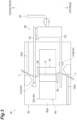
- FIG. 3 is a front view of the yarn joining device 26.
- the winding device 14 side is referred to as the downstream side
- the yarn supply device 12 side is referred to as the upstream side, for convenience sake.
- the yarn Y traveling path (yarn path) side of the yarn joining device 26 is referred to as the front side
- the opposite side is referred to as the rear side.
- the direction orthogonal to the vertical direction and the front-rear direction is referred to as the left-right direction.
- the yarn end of the yarn Y on the winding device 14 side is referred to as a first yarn end
- the yarn end of the yarn Y on the yarn supply device 12 side is referred to as a second yarn end.
- the yarn joining device 26 includes a front plate (contact member) 90, an untwisting unit 40 including a first untwisting pipe member 41A and a second untwisting pipe member 41B, a yarn joining unit 50 configured to join yarns by injection of compressed air, a pair of yarn gathering levers (not illustrated) capable of turning such that the untwisting unit 40 is sandwiched, a yarn holding member 80 including first and second yarn holding levers 82 and 83 capable of turning such that the yarn joining unit 50 is sandwiched, and an air guide 94.
- the front plate 90 has a plate shape having a thickness direction in the front-rear direction.
- a front surface (contact surface) 90a of the front plate 90 is planar along the yarn traveling direction.
- the yarn joining unit 50 is provided on the front surface 90a of the front plate 90.
- the front surface 90a of the front plate 90 has a first yarn end entry that is an opening of the first untwisting pipe member 41A on the downstream side of the yarn joining unit 50 and has a second yarn end entry that is an opening of the second untwisting pipe member 41B on the upstream side of the yarn joining unit 50.
- the front surface 90a of the front plate 90 has a first guide 45A on the downstream side of the first untwisting pipe member 41A and a second guide 45B on the upstream side of the second untwisting pipe member 41B.
- the first and second guides 45A and 45B are disposed to face each other with the yarn joining unit 50 interposed therebetween.
- the first and second guides 45A and 45B guide the yarns Y guided by the first and second catch guide devices 30 and 32, respectively.
- the first untwisting pipe member 41A takes in and untwists the first yarn end by the action of compressed air.
- the second untwisting pipe member 41B takes in and untwists the second yarn end by the action of compressed air.
- the yarn joining unit 50 twists and joins the first yarn end untwisted by the first untwisting pipe member 41A and the second yarn end untwisted by the second untwisting pipe member 41B, by the action of compressed air.
- the first and second yarn ends are pulled out of the first and second untwisting pipe members 41A and 41B by the yarn gathering levers (not illustrated) while being retained by a clamp (not illustrated) .
- the first and second yarn ends are held in the vicinity of the yarn joining unit 50 by the first and second yarn holding levers 82 and 83.
- the yarn holding member 80 is connected to a drive source (not illustrated) such as a stepping motor through a cam link mechanism 95.
- the yarn holding member 80 is movable in directions closer to and away from the front surface 90a of the front plate 90 by the driving force of the driving source. That is, the first and second yarn holding levers 82 and 83 of the yarn holding member 80 turn (rotate) such that the distal ends thereof move closer to and away from the front surface 90a of the front plate 90 by the driving force of the driving source.
- the yarn holding member 80 comes into abutment with the front surface 90a of the front plate 90 to hold the first and second yarn ends in cooperation with the front surface 90a.
- the distal ends of the first and second yarn holding levers 82 and 83 may be biased closer to the front plate 90, for example, by a torsion coil spring (not illustrated) .
- the air guide 94 is a member that guides the compressed air injected in the yarn joining unit 50 and is provided to partially block the upper and lower openings of a yarn joining chamber 113 in which the first and second yarn ends are introduced in the yarn joining unit 50.
- the first and second yarn gathering levers (not illustrated) and the first and second yarn holding levers 82 and 83 turn toward the front plate 90.
- the yarn Y on the downstream side and the yarn Y on the upstream side that are guided by the first and second catch guide devices 30 and 32 are drawn toward the untwisting unit 40.
- the upper yarn Y and the lower yarn Y are then retained by the clamp and cut by a cutter in this state.
- the first yarn end is fed into the first untwisting pipe member 41A
- the second yarn end is fed into the second untwisting pipe member 41B.
- Injection of compressed air is started in the first and second untwisting pipe members 41A and 41B, and the first and second yarn ends are untwisted by the action of compressed air.
- the first and second yarn gathering levers (not illustrated) further turn.
- the first yarn end is pulled out of the first pipe member 41A and the second yarn end is pulled out of the second pipe member 41B.
- the first yarn end and the second yarn end are held in the vicinity of the yarn joining unit 50 by the first and second yarn holding levers 82 and 83.
- Injection of compressed air is started in the yarn joining unit 50, and the first yarn end and the second yarn end untwisted are twisted together by the action of compressed air.
- the first and second yarn gathering levers (not illustrated) and the first and second yarn holding levers 82 and 83 turn in the opposite direction.
- the retention of the yarn Y on the upper side and the yarn Y on the lower side by the clamp is released.
- the joined yarn Y returns onto the traveling path on the front side of the yarn joining device 26.
- the yarn joining unit 50 will be described in detail with reference to FIG. 4 to FIG. 7 .
- the yarn joining unit 50 has a yarn joining nozzle assembly 100 into which the first yarn end and the second yarn end each untwisted are introduced and in which yarn joining of the first yarn end and the second yarn end is performed.
- the yarn joining nozzle assembly 100 which is formed in a rectangular parallelepipedal block-like shape, is fixed in the winder unit 3 so as to be directed to the front (refer to FIG. 2 ) .
- the yarn joining nozzle assembly 100 includes a yarn joining nozzle 70 and a support block 60 housing and supporting the yarn joining nozzle 70, for example.
- the yarn joining nozzle 70 and the support block 60 are both made of metal.
- the yarn joining nozzle 70 is made of metal such as iron, stainless steel (SUS), or brass.
- the support block 60 is made of metal such as zinc or aluminum.
- the metal forming the yarn joining nozzle 70 (a first metal) is different from the metal forming the yarn joining unit 50 (a second metal).
- the support block 60 includes a central part 63 housing the yarn joining nozzle 70, and a first side part 61 and a second side part 62 disposed on both sides of the central part 63.
- the first side part 61, the second side part 62, and the central part 63 are integrally molded (integrally formed) by casting such as die casting.
- the surface of the support block 60 is not painted, exposing the material making up the support block 60.
- the central part 63 has yarn introducing surfaces 63f, which are a pair of sloping surfaces widening toward the front.
- the central part 63 has a nozzle housing part 64, which is a rectangular recess continuous with the yarn introducing surfaces 63f .
- the nozzle housing part 64 is defined by a first side wall surface 63a and a second side wall surface 63b facing each other and being parallel to each other and a rear wall surface 63c connecting the rear ends of the first side wall surface 63a and the second side wall surface 63b to each other.
- the size and shape of the nozzle housing part 64 are formed so as to be able to just house the yarn joining nozzle 70.
- the yarn joining nozzle 70 fits into (is housed in) the nozzle housing part 64 of the support block 60 and is bonded to the support block 60.
- the yarn joining nozzle 70 and the support block 60 are fixed and integrated with each other with an adhesive, thus enhancing the strength of the yarn joining nozzle assembly 100.
- the yarn joining nozzle 70 includes a first side surface 75 facing the first side wall surface 63a of the support block 60, a second side surface 76 facing the second side wall surface 63b of the support block 60, and a back surface 77 facing the rear wall surface 63c of the support block 60.
- the first side surface 75, the second side surface 76, and the back surface 77 are all rectangular areas, and the yarn joining nozzle 70 is provided with a chamber forming part 74 described below.
- the chamber forming part 74 is a space recessed from the first side surface 75, the second side surface 76, and the back surface 77, and thus substantially only a peripheral part is left on each of the first side surface 75, the second side surface 76, and the back surface 77.
- a first side surface edge 75a of the first side surface 75 and a second side surface edge 76a of the second side surface 76 are both U-shaped opened toward the rear.
- the first side surface edge 75a and the second side surface edge 76a form flat surfaces directed toward the side and have the same size and shape, for example.
- Back surface edges 77a of the back surface 77 form two parallel flat surfaces directed to the rear.
- a nozzle body 71 of the yarn joining nozzle 70 includes a substantially cylindrical central block part 71a and a chamber wall surface 71b formed continuously with both side surfaces and a rear surface of the central block part 71a and extending in a U-shape. With the yarn joining nozzle 70 bonded to the support block 60, a chamber C (refer to FIG. 5 ) extending in a U-shape is formed between each of three surfaces of the first side wall surface 63a, the second side wall surface 63b, and the rear wall surface 63c, and the chamber wall surface 71b.
- the yarn joining nozzle 70 and the support block 60 are bonded together with an epoxy resin thermosetting adhesive, for example.
- the yarn joining nozzle 70 is a sintered body molded of the metal described above (the first metal) . As illustrated in FIG. 7 , the yarn joining nozzle 70 has a yarn joining space 72 formed to pass therethrough in a first direction and a yarn inserting gap 73 connected to the yarn joining space 72 and communicating with the inside and the outside of the yarn joining nozzle 70.
- the first direction is a direction parallel to a yarn traveling path L (that is, the traveling direction of the yarn Y) illustrated in FIG. 7 .
- the yarn inserting gap 73 connects to the yarn joining space 72 in the front-rear direction (a second direction and the horizontal direction) orthogonal to the first direction and causes the inside and the outside of the yarn joining nozzle 70 to communicate with each other in the front-rear direction.
- the nozzle body 71 includes a pair of yarn introducing surfaces 71f disposed to be continuous with the pair of yarn introducing surfaces 63f of the support block 60 via an adhesive and sloping in a V shape in plan view.
- the yarn inserting gap 73 connects to the yarn introducing surfaces 71f and is a gap for inserting the yarn Y into the yarn joining space 72 from the front (from the second direction).
- the yarn joining space 72 has an upstream yarn joining space (a first yarn joining space) 72b including two upstream injection holes (first passing holes) 79b, for example, through which compressed air passes and a downstream yarn joining space (a second yarn joining space) 72a including two downstream injection holes (second passing holes) 79a, for example, through which compressed air passes.
- the central block part 71a has two upstream injection channels 78b connecting the chamber C and upstream yarn joining space 72b to each other and two downstream injection channels 78a connecting the chamber C and the downstream yarn joining space 72a to each other.
- the upstream injection channel 78b opens into the upstream yarn joining space 72b, and the openings are the upstream injection holes 79b.
- the downstream injection channel 78a opens into the downstream yarn joining space 72a, and the openings are the downstream injection holes 79a.
- the upstream injection channel 78b is formed from the first side surface 75 toward the yarn traveling path L and from the front to the rear.
- the downstream injection channel 78a is formed from the second side surface 76 toward the yarn traveling path L and from the front to the rear.
- the yarn joining device 26 is a water splicer injecting liquid such as water into the channels for compressed air.
- the upstream injection channel 78b and the downstream injection channel 78a are twisting channels configured to twist the yarn ends of two yarns together by compressed air with, for example, water (liquid) added passing through the channels. Compressed air with, for example, water (liquid) added is also injected in the first untwisting pipe member 41A and the second untwisting pipe member 41B.
- the downstream yarn joining space 72a is adjacent to and communicates with the upstream yarn joining space 72b in the first direction.
- the upstream yarn joining space 72b and the downstream yarn joining space 72a are cylindrical in shape with the same size and shape.
- Each of the upstream yarn joining space 72b and downstream yarn joining space 72a is defined by a cylindrical peripheral surface.
- the upstream yarn joining space 72b and the downstream yarn joining space 72a are displaced (offset) in a third direction, which is orthogonal to both of the first direction and the second direction, with respect to the yarn traveling path L.
- the central axis of the upstream yarn joining space 72b extends in the first direction and is displaced in one in the third direction with respect to the yarn traveling path L.
- the central axis of the downstream yarn joining space 72a also extends in the first direction but is displaced in the other in the third direction with respect to the yarn traveling path L.
- the upstream yarn joining space 72b and the downstream yarn joining space 72a are eccentric to the one and the other sides in the third direction with respect to the yarn traveling path L.
- the upstream yarn joining space 72b and the downstream yarn joining space 72a overlap with one another in an area including the yarn traveling path L in plan view.
- the first side part 61 and the central part 63 of the support block 60 have an air introducing path 66 extending in a V shape from an entrance 66a toward an exit 66b.
- the entrance 66a is formed on a rear surface of the support block 60 and the exit 66b is formed on the first side wall surface 63a of the central part 63.
- the air introducing path 66 includes a first straight part 66A including the entrance 66a and a second straight part 66B including the exit 66b, for example.
- the exit 66b and the upstream injection channel 78b are preferably displaced in the second direction from the viewpoint that this configuration reduces the difference in compressed air injected from the upstream injection channel 78b and the downstream injection channel 78a.
- the shape of the air introducing path 66 is not limited to this form.
- the second straight part 66B may be extended to form an exit of the air introducing path 66 on a side surface of the support block 60, for example.
- the air introducing path 66, the chamber C, the downstream injection channel 78a (the downstream injection holes 79a), and the upstream injection channel 78b (the upstream injection holes 79b) form a path for compressed air.
- Compressed air passes through the upstream injection holes 79b, whereby the compressed air is injected from the upstream injection holes 79b.
- Compressed air passes through the downstream injection holes 79a, whereby the compressed air is injected from the downstream injection holes 79a.
- Yarn joining of the first yarn end and the second yarn end is performed through the compressed air injected into the upstream yarn joining space 72b through the upstream injection channel 78b (the upstream injection holes 79b) and the compressed air injected into the downstream yarn joining space 72a through the downstream injection channel 78a (the downstream injection holes 79a).
- the yarn joining nozzle 70 is subjected to plating treatment with a metal different from the metal forming the yarn joining nozzle 70 or the metal forming the support block 60. That is, the yarn joining nozzle 70 has a plated part in which the surface of the first metal is coated with a metal different from the first metal. More specifically, the plating treatment for the yarn joining nozzle 70 is electroless nickel plating treatment. The plated part is an electroless nickel-plated coating. The plated part is an amorphous nickel coating formed uniformly over the entire surface of the first metal forming the body of the yarn joining nozzle 70.
- the arithmetic average roughness (Ra) of surface texture of the entire yarn joining nozzle 70 is more than 0 and 1.5 or less, for example.
- the arithmetic average roughness (Ra) of the surface texture of the entire yarn joining nozzle 70 may be 0.5 or more. Even if the arithmetic average roughness (Ra) of the surface texture of the yarn joining nozzle 70 is made smaller than 0.5, the occurrence of yarn snagging during yarn joining does not change very much. Consequently, yarn quality does not change very much either. Thus, by setting the arithmetic average roughness (Ra) of surface texture of the yarn joining nozzle 70 to 0.5 or more and 1.5 or less, it is possible to reduce the manufacturing cost of the yarn joining nozzle 70 while also obtaining sufficient yarn quality.
- the plated part has a thickness of 5 ⁇ m or more and 20 ⁇ m or less, for example.
- the hardness of the electroless nickel-plated coating is 450 HV or more in terms of Vickers hardness, for example. Due to the small thickness of the plated part, the plated part does not significantly affect the arithmetic average roughness of surface texture of the yarn joining nozzle 70. Instead, the plated part affects the hardness.
- the unit of arithmetic average roughness of surface texture is " ⁇ m.”
- the region in which the arithmetic average roughness of surface texture and the hardness are adjusted to the above numerical ranges by the electroless nickel-plated coating may be the entire surface of the yarn joining nozzle 70 or only part of the surface of the yarn joining nozzle 70.
- the plating treatment surface treatment
- the plating treatment may be applied only to a first area M1b, which is a peripheral surface on the outer peripheral side of the upstream yarn joining space 72b, and a second area M2b closer to the yarn traveling path L in the upstream yarn joining space 72b.
- the peripheral surface on the outer peripheral side of the yarn joining space 72 can also be said to be "a peripheral surface defining the yarn joining space 72."
- the plating treatment may be applied only to a first area M1a, which is a peripheral surface on the outer peripheral side of the downstream yarn joining space 72a, and a second area M2a closer to the yarn traveling path L in the downstream yarn joining space 72a. That is, the plating treatment (surface treatment) may be applied only to a minimum area including the first area M1b, the second area M2b, the first area M1a, and the second area M2a.
- the first area M1b, the second area M2b, the first area M1a, and the second area M2a are indicated by bold lines.
- a method for manufacturing the yarn joining nozzle 70 will be described.
- a kneaded product obtained by kneading for example, a powdery metallic material and a binder forming the yarn joining nozzle 70 is injected into a mold for forming the yarn joiningnozzle 70. Furthermore, the kneaded product is heated to remove the binder . The kneaded product from which the binder has been removed is sintered to form an intermediate of the yarn joining nozzles 70. Sintering can provide high hardenability in the yarn joining nozzle 70.
- the entire surface of the yarn joining nozzle 70 is ground by shot blast treatment.
- the shot blast treatment has a meaning as pretreatment (base treatment) for forming the plated part.
- electroless nickel plating treatment is applied to the entire part or part of a surface of the yarn joining nozzle 70. Subsequently, the yarn joining nozzle 70 is bonded and fixed to the support block 60.
- the metallic yarn joining nozzle 70 improves strength and thus prevents breakage of the yarn joining nozzle 70.
- the arithmetic average roughness (Ra) of surface texture of at least part of the peripheral surface on the outer peripheral side of the yarn joining space 72 is more than 0 and 1.5 or less, and thus the occurrence of the snagging of the yarn Y during yarn joining is reduced, thereby improving yarn quality.
- the arithmetic average roughness (Ra) of surface texture of at least part of the peripheral surface on the outer peripheral side of the yarn joining space 72 is 0.5 or more and 1.5 or less, and thus it is possible to reduce the manufacturing cost of the yarn joining nozzle 70 while also obtaining certain yarn quality.
- the yarn joining nozzle has the plated part in which the surface of the first metal is coated with the metal different from the first metal.
- the surface of the first metal as a base material is covered with the plated part.
- the two types of metals enhance hardness.
- the support block 60 is formed of the second metal different from the firstmetal. Bonding with the thermosetting adhesive requires treatment under high temperature conditions (heating treatment).
- the thermosetting adhesive is excellent in terms of adhesive strength.
- conventional ceramic nozzles cannot withstand high temperature conditions in that they cause stress based on the difference in thermal expansion between a ceramic nozzle and a metallic support block, leading to nozzle breakage, for example.
- the yarnjoining nozzle being formed of the first metal and the support block being formed of the second metal can reduce the possibility of the yarn joining nozzle 70 breaking due to stress based on thermal expansion under high temperature conditions.
- the yarn joining device 26 is a water splicer injecting liquid such as water into the channels for compressed air.
- the upstream injection channel 78b and the downstream injection channel 78a are twisting channels configured to twist the yarn ends of two yarns together by compressed air with water (liquid) added passing through the channels. Water, together with air, is injected into the yarn joining space 72 of the yarn joining nozzle 70 through the upstream injection channel 78b and the downstream injection channel 78a.
- the yarn joining nozzle 70 and the support block 60 are bonded together with the epoxy resin adhesive, and thus the adhesive strength is maintained despite the presence of a liquid component.
- the plated part is an electroless nickel-plated coating.
- the surface of the first metal can be uniformly covered with the electroless nickel-plated coating to form the plated part (a plated layer) uniformly even when the shape is complicated.
- electroplating is employed, the thickness of the plated part varies from place to place, and variations in thickness are likely to occur, but such non-uniformity is avoided.
- Electroless nickel plating is performed by immersion in a solution. Thus, the plating treatment can be performed even if the shape of the yarn joining nozzle 70 is complicated.
- the part in which the plated part is required is only a part to be in contact with the yarn, but considering simplicity in manufacture, the plated part is formed on the entire surface of the yarn joining nozzle 70 (the first metal).
- the plated part has a thickness of 5 um or more and 20 um or less. A smaller thickness of the plated part makes the dimensions of the yarn joining nozzle 70 more substantially the same as the dimensions of the base material (the first metal) and stabilizes the dimension accuracy of the yarn joining nozzle 70 as a finished product.
- the yarn joining nozzle is molded by injecting a kneaded product obtained by kneading the first metal and a binder into a mold, removing the binder by heating, and then sintering the kneaded product. Sintering provides high hardenability in the yarn joining nozzle 70.
- the yarn joining nozzle 70 is molded by injection molding, and thus there is no need for performing machining. It can also be manufactured with higher accuracy than by casting.
- the yarn joining nozzle 70 is formed with a mold, and thus the yarn joining nozzle 70 can be formed without machining, thus reducing man-hours.
- performing machining can produce burrs or the like, but injection molding is less likely to produce unnecessary parts on the molded product.
- Casting can produce air holes when metal is poured. With the above method of manufacture, dimensional accuracy is enhanced.
- the yarn joining device 26 may be an air splicer injecting only compressed air into the channels for compressed air, for example.
- the number of injection holes formed in the yarn joining nozzle may be one for the entire yarn joining space. Alternatively, it may be one for each of the first yarn joining space and the second yarn joining space.
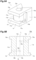
- a yarn joining nozzle 70A may be provided in which the upstream yarn joining space 72b and the downstream yarn joining space 72a are provided coaxially with respect to the yarn traveling path L.
- the sectional shape of the upstream yarn joining space 72b and the downstream yarn joining space 72a may each be semicircular in plan view (in a section perpendicular to the yarn traveling path L).
- the sectional shape of the upstream yarn joining space 72b and the downstream yarn joining space 72a may each be polygonal (e.g., triangular, quadrangular (including rhombic and trapezoidal), pentagonal, or the like) in plan view.
- the yarn joining nozzle 70 may be formed from a solid metallic material without performing plating treatment.
- the surface hardness of the yarn joining nozzle 70 becomes 700 HV or more in terms of Vickers hardness, for example.
- the baking treatment achieves high hardness. It also provides superior resistance to wear and tear compared to ordinary decorative plating or rust-preventive plating.
- the arithmetic average roughness (Ra) of surface texture of the entire part or part of the surface of the yarn joining nozzle 70 is more than 0 and 1.5 or less.
- the arithmetic average roughness (Ra) of surface texture of the entire part or part of the surface of the yarn joining nozzle 70 is 0.5 or more and 1.5 or less.
- the yarn joining nozzle subjected to the baking treatment can be distinguished from the yarn joining nozzle subjected to the plating treatment in appearance.
- the treatment may be applied in order of the shot blast treatment, the plating treatment, and the baking treatment.
- high hardness similar to that described above e.g., 700 HV or more
- the yarn joining device according to an aspect of the present disclosure is applied to the winder unit 3.
- the yarn joining device according to an aspect of the present disclosure may be applied to the winding unit of a spinning machine or a work vehicle moving between a plurality of winding units.
- the adhesive for joining the yarn joining nozzle 70 and the support block 60 together may be an adhesive containing a curing agent.
- the support block 60 may be made of resin.
- the support block is larger than the yarn joining nozzle, and thus when a support block made of resin is used for a yarn joining nozzle made of metal, expansion of the yarn joining nozzle due to elevated temperatures has little effect on the support block.
- the yarn joining nozzle may possibly break, but in the above case, the support block is unlikely to break.
- the yarn joining nozzle 70 and the support block 60 which are configured as separate components, may be configured as an integrated component.
- the yarn joining nozzle 70 has an air introducing path connected to an air supply path outside the yarn joining device 26, a chamber which is a space connected to the downstream side of the air introducing path, and a passing hole connected to the chamber and through which compressed air passes to the yarn joining space.
- the air introducing path, the chamber, the injection hole, the yarn joining space, and the yarn inserting gap are provided in the yarn joining nozzle formed as an integral (one piece) component by the first metal.
- An integral component of the yarn joining nozzle 70 and the support block 60 can be shaped with a metal 3D printer, for example.
- the yarn joining nozzle 70 may be formed by machining or casting.
Landscapes
- Yarns And Mechanical Finishing Of Yarns Or Ropes (AREA)
- Looms (AREA)
- Replacing, Conveying, And Pick-Finding For Filamentary Materials (AREA)
- Spinning Or Twisting Of Yarns (AREA)
Abstract
Description
- The present disclosure relates to a yarn joining device.
- Conventionally, a yarn joining unit (a yarn joining device) having a yarn joining chamber, which is a space in which yarn joining is performed by the action of compressed air, is known. The yarn joining chamber is formed in a nozzle, and compressed air is injected to the yarn joining chamber through a path and an injection hole of the nozzle, for example. A first yarn end and a second yarn end untwisted are twisted together by the action of the compressed air. The nozzle is formed of ceramic, for example. The nozzle is housed in an opening of a support block and is fixed. The support block is formed of metal such as aluminum or resin, for example. (Patent Document 1:
Japanese Unexamined Patent Publication No. 2021-091501 - Ceramic nozzles in conventional yarn joining devices are excellent in terms of resistance to wear and tear against yarns. However, there is a problem in that when impact or stress is applied to nozzles, ceramic nozzles are likely to break.
- An object of the present disclosure is to provide a yarn joining device with a metallic nozzle in order to prevent nozzle breakage, thus improving strength and improving yarn quality.
- A yarn joining device according to an aspect of the present disclosure includes a yarn joining nozzle formed of a first metal. The yarn joining nozzle has a yarn joining space formed to pass through the yarn joining nozzle in a first direction and a yarn inserting gap connected to the yarn joining space in a second direction orthogonal to the first direction and communicating with an inside and an outside of the yarn joining nozzle in the second direction. An arithmetic average roughness (Ra) of surface texture of at least part of a peripheral surface on an outer peripheral side of the yarn joining space is more than 0 and 1.5 or less. "Defining a yarn joining space" means "determining the boundary of the yarn joining space" or "forming the boundary of the yarn joining space." The "arithmetic average roughness" is an indicator defined by the Japanese Industrial Standards (JIS) .
- With this yarn joining device, the metallic yarn joining nozzle improves strength and thus prevents breakage of the yarn joining nozzle. The arithmetic average roughness (Ra) of surface texture of at least part of the peripheral surface on the outer peripheral side of the yarn joining space is more than 0 and 1.5 or less, and thus the occurrence of yarn snagging during yarn joining is reduced, thereby improving yarn quality.
- The arithmetic average roughness (Ra) of surface texture of at least part of the peripheral surface on the outer peripheral side of the yarn joining space may be 0.5 or more. Even if the arithmetic average roughness (Ra) of surface texture is reduced to less than 0.5, the occurrence of yarn snagging during yarn joining does not change significantly. Thus, by setting the arithmetic average roughness (Ra) of surface texture of the yarn joining nozzle to 0.5 or more and 1.5 or less, it is possible to reduce the manufacturing cost of the yarn joining nozzle while obtaining sufficient yarn quality.
- The yarn joining nozzle may have a plated part in which a surface of the first metal is coated with a metal different from the first metal. In this case, the surface of the first metal as a base material is covered with the plated part. The two types of metals enhance hardness. By adjusting the arithmetic average roughness of surface texture of the plated part to the above range, the yarn joining nozzle with excellent yarn quality can be easily achieved.
- The yarn joining space may have a first yarn joining space including one or a plurality of first passing holes through which compressed air passes, and a second yarn joining space adjacent to and communicating with the first yarn joining space in the first direction and including one or a plurality of second passing holes through which the compressed air passes. The plated part may be an electroless nickel-plated coating. Even when the yarn joining nozzle has a complicated shape, the electroless nickel-plated coating can uniformly cover the surface of the first metal.
- The plated part may have a thickness of 5 µm or more and 20 µm or less. A smaller thickness of the plated part makes the dimensions of the yarn joining nozzle more substantially the same as the dimensions of the base material (the first metal) and stabilizes the dimension accuracy of the yarn joining nozzle as a finished product.
- The yarn joining nozzle may be subjected to baking treatment. The baking treatment achieves high hardness. It also provides superior resistance to wear and tear compared to ordinary decorative plating or rust-preventive plating.
- The yarn joining nozzle may be molded by injecting and sintering a kneaded product obtained by kneading the first metal and a binder. The yarn joining nozzle is molded by injection molding, and thus there is no need for performing machining. It can also be manufactured with higher accuracy than by casting.
- The surface of the first metal of the yarn joining nozzle may be ground by shot blast treatment. The shot blast treatment can also adjust (reduce) the arithmetic average roughness of surface texture of fine parts on the surface of the first metal, by grinding.
- The yarn joining device may include a support block housing the yarn joining nozzle. The yarn joining nozzle and the support block may be bonded together with an epoxy resin thermosetting adhesive, and the support block may be formed of a second metal different from the first metal. Bonding with the thermosetting adhesive requires treatment under high temperature conditions (heating treatment). Thermosetting adhesives are excellent in terms of adhesive strength, but conventional ceramic nozzles or the like cannot withstand high temperature conditions in that they cause stress based on thermal expansion, leading to nozzle breakage, for example. The yarn joining nozzle being formed of the first metal and the support block being formed of the second metal can reduce the possibility of breakage due to thermal expansion under high temperature conditions.
- The yarn joining device may include a twisting channel configured to twist yarn ends of two yarns together by compressed air with liquid added passing through the twisting channel. In this case, the liquid, together with air, is injected into the yarn joining space of the yarn joining nozzle through the twisting channel. The yarn joining nozzle and the support block are bonded together with the epoxy resin thermosetting adhesive, and thus the adhesive strength is maintained despite the presence of a liquid component. An adhesive that requires a curing agent may cause variations in adhesive strength based on variations in the concentration of the curing agent in the adhesive. If there is a liquid component under such a situation, adhesive strength is not necessarily maintained.
- The yarn joining nozzle may have an air introducing path connected to an air supply path outside the yarn joining device, a chamber, which is a space connected to a downstream side of the air introducing path, and a passing hole connected to the chamber and through which compressed air passes to the yarn joining space. The air introducing path, the chamber, the passing hole, the yarn joining space, and the yarn inserting gap may be provided in the yarn joining nozzle formed as an integral component made from the first metal. Such an integrated component is shaped by a metal 3D printer, for example. With this method of shaping, it is possible to easily manufacture the yarn joining nozzle with a complicated shape.
- The yarn joining nozzle may have a plated part in which a surface of the first metal is coated with a metal different from the first metal. In this case, the surface of the first metal as a base material is covered with the plated part. The two types of metals enhance hardness. By adjusting the arithmetic average roughness of surface texture of the plated part to the above range, the yarn joining nozzle with excellent yarn quality can be easily achieved. Furthermore, when the yarn joining nozzle is shaped by the metal 3D printer, the plated part can provide a desired arithmetic average roughness of surface texture.
- According to the present disclosure, the metallic yarn joining nozzle improves strength. In addition, the occurrence of yarn snagging during yarn joining is reduced, thus improving yarn quality.
-
-
FIG. 1 is a front view of an automatic winder; -
FIG. 2 is a side view of a winder unit inFIG. 1 ; -
FIG. 3 is a front view of a yarn joining device according to an embodiment; -
FIG. 4 is a perspective view of a yarn joining nozzle assembly of the yarn joining device according to the embodiment; -
FIG. 5 is a plan view of a channel structure of the yarn joining nozzle assembly inFIG. 4 ; -
FIG. 6A is a perspective view of the yarn joining nozzle inFIG. 4 , viewed from the rear; -
FIG. 6B is a perspective view of the yarn joining nozzle, viewed from obliquely above; -
FIG. 7 is a sectional view cut along the VII-VII line inFIG. 6B ; -
FIG. 8A is a perspective view of a yarn joining nozzle according to a modification, viewed from the rear; and -
FIG. 8B is a sectional view of the yarn joining nozzle along an axial line extending in a first direction. - Embodiments of the present disclosure will be described with reference to the accompanying drawings. In the description of the drawings, like elements are denoted by the same reference signs and an overlapping description is omitted.
- As illustrated in
FIG. 1 , anautomatic winder 1 includes a plurality ofwinder units 3 arranged in a row, amachine control device 5, and adoffer 7. Themachine control device 5 can communicate with each of the winder units (winding devices) 3. The operator of theautomatic winder 1 can collectively control a plurality ofwinder units 3 by operating themachine control device 5 as appropriate. Each of thewinder units 3 unwinds yarn Y from a yarn supply bobbin SB while traversing the yarn Y and winds the yarn Y onto a winding bobbin WB to form a package P. When the package P becomes full (a state in which a predetermined amount of yarn is wound) in eachwinder unit 3, thedoffer 7 travels to the position of thewinder unit 3, removes the full package, and sets an empty winding bobbin WB. - As illustrated in
FIG. 2 , thewinder unit 3 includes aunit controller 10, ayarn supply device 12, and a windingdevice 14. Theunit controller 10 includes, for example, a central processing unit (CPU) and a read only memory (ROM). The ROM stores a program for controlling each component of thewinder unit 3. The CPU executes the program stored in the ROM. Theunit controller 10 controls the operation of each part in thewinder unit 3 and, as part of the control, controls the injection of compressed air in ayarn joining unit 50 described below. - The
yarn supply device 12 supports a yarn supply bobbin SB placed on a not-illustrated transportation tray at a predetermined position. Theyarn supply device 12 unwinds the yarn Y from the yarn supply bobbin SB and pulls out the yarn Y from the yarn supply bobbin SB. Theyarn supply device 12 supplies the yarn Y. Theyarn supply device 12 is not limited to a transportation tray-type device and may be, for example, a magazine-type device. - The winding
device 14 includes acradle 16 and a windingdrum 18. Thecradle 16 sandwiches a winding bobbin WB and thereby rotatably supports the winding bobbin WB (or the package P). The windingdrum 18 traverses the yarn Y on the surface of the package P and rotates the package P. The windingdrum 18 is driven to rotate by a not-illustrated drum drive motor. With the outer periphery of the package P in contact with the windingdrum 18, the windingdrum 18 is driven to rotate so that the package P follows the rotation. The outer peripheral surface of the windingdrum 18 has a spiral traverse groove. The yarn Y unwound from the yarn supply bobbin SB is wound onto the surface of the package P while being traversed in a constant width with the traverse groove . The package P having a constant winding width thus can be formed. - Each
winder unit 3 includes anunwinding assisting device 20, atension applying device 22, atension detecting device 24, ayarn joining device 26, and ayarn monitoring device 28 in this order from theyarn supply device 12, in a yarn path between theyarn supply device 12 and the windingdevice 14. A firstcatch guide device 30 and a secondcatch guide device 32 are disposed in the vicinity of theyarn joining device 26. - The unwinding assisting
device 20 prevents the yarn Y unwound from the yarn supply bobbin SB from being swung excessively by centrifugal force and unwinds the yarn Y from the yarn supply bobbin SB appropriately. Thetension applying device 22 applies a predetermined tension to the traveling yarn Y. In the present embodiment, thetension applying device 22 is a gate-type device in which movable comb teeth are disposed for fixed comb teeth. - The
tension detecting device 24 detects the tension of the traveling yarn Y between theyarn supply device 12 and the windingdevice 14. Theyarn joining device 26 joins the yarn Y on theyarn supply device 12 side and the yarn Y on the windingdevice 14 side when the yarn Y is broken between theyarn supply device 12 and the windingdevice 14 for some reason. - The
yarn monitoring device 28 monitors a state of the yarn Y traveling on the yarn path and detects whether there is a yarn defect, based on the monitored information. The yarn defect is, for example, at least one of abnormal thickness of the yarn Y, a foreign matter contained in the yarn Y, yarn breakage, and the like. - The first
catch guide device 30 can turn from a standby position on theyarn supply device 12 side to a catch position on the windingdevice 14 side. The firstcatch guide device 30 catches the yarn Y at the catch position and guides the yarn Y to theyarn joining device 26. The secondcatch guide device 32 can turn from a standby position on theyarn supply device 12 side to a catch position on the windingdevice 14 side. The secondcatch guide device 32 catches the yarn Y at the catch position and guides the yarn Y to theyarn joining device 26. - The
yarn joining device 26 described above will now be described in detail. -
FIG. 3 is a front view of theyarn joining device 26. In the following description, the windingdevice 14 side is referred to as the downstream side, and theyarn supply device 12 side is referred to as the upstream side, for convenience sake. The yarn Y traveling path (yarn path) side of theyarn joining device 26 is referred to as the front side, and the opposite side is referred to as the rear side. The direction orthogonal to the vertical direction and the front-rear direction is referred to as the left-right direction. The yarn end of the yarn Y on the windingdevice 14 side is referred to as a first yarn end, and the yarn end of the yarn Y on theyarn supply device 12 side is referred to as a second yarn end. - As illustrated in
FIG. 3 , theyarn joining device 26 includes a front plate (contact member) 90, an untwistingunit 40 including a firstuntwisting pipe member 41A and a seconduntwisting pipe member 41B, ayarn joining unit 50 configured to join yarns by injection of compressed air, a pair of yarn gathering levers (not illustrated) capable of turning such that the untwistingunit 40 is sandwiched, ayarn holding member 80 including first and secondyarn holding levers yarn joining unit 50 is sandwiched, and anair guide 94. - The
front plate 90 has a plate shape having a thickness direction in the front-rear direction. A front surface (contact surface) 90a of thefront plate 90 is planar along the yarn traveling direction. Theyarn joining unit 50 is provided on thefront surface 90a of thefront plate 90. Thefront surface 90a of thefront plate 90 has a first yarn end entry that is an opening of the firstuntwisting pipe member 41A on the downstream side of theyarn joining unit 50 and has a second yarn end entry that is an opening of the seconduntwisting pipe member 41B on the upstream side of theyarn joining unit 50. - The
front surface 90a of thefront plate 90 has afirst guide 45A on the downstream side of the firstuntwisting pipe member 41A and asecond guide 45B on the upstream side of the seconduntwisting pipe member 41B. The first andsecond guides yarn joining unit 50 interposed therebetween. The first andsecond guides catch guide devices - The first
untwisting pipe member 41A takes in and untwists the first yarn end by the action of compressed air. The seconduntwisting pipe member 41B takes in and untwists the second yarn end by the action of compressed air. Theyarn joining unit 50 twists and joins the first yarn end untwisted by the firstuntwisting pipe member 41A and the second yarn end untwisted by the seconduntwisting pipe member 41B, by the action of compressed air. When the yarn ends are twisted together in theyarn joining unit 50, the first and second yarn ends are pulled out of the first and seconduntwisting pipe members yarn joining unit 50 by the first and secondyarn holding levers - The
yarn holding member 80 is connected to a drive source (not illustrated) such as a stepping motor through acam link mechanism 95. Theyarn holding member 80 is movable in directions closer to and away from thefront surface 90a of thefront plate 90 by the driving force of the driving source. That is, the first and secondyarn holding levers yarn holding member 80 turn (rotate) such that the distal ends thereof move closer to and away from thefront surface 90a of thefront plate 90 by the driving force of the driving source. Theyarn holding member 80 comes into abutment with thefront surface 90a of thefront plate 90 to hold the first and second yarn ends in cooperation with thefront surface 90a. The distal ends of the first and secondyarn holding levers front plate 90, for example, by a torsion coil spring (not illustrated) . Theair guide 94 is a member that guides the compressed air injected in theyarn joining unit 50 and is provided to partially block the upper and lower openings of a yarn joining chamber 113 in which the first and second yarn ends are introduced in theyarn joining unit 50. - In the
yarn joining device 26 configured as described above, first, the first and second yarn gathering levers (not illustrated) and the first and secondyarn holding levers front plate 90. As a result, the yarn Y on the downstream side and the yarn Y on the upstream side that are guided by the first and secondcatch guide devices unit 40. The upper yarn Y and the lower yarn Y are then retained by the clamp and cut by a cutter in this state. The first yarn end is fed into the firstuntwisting pipe member 41A, and the second yarn end is fed into the seconduntwisting pipe member 41B. Injection of compressed air is started in the first and seconduntwisting pipe members - Subsequently, the first and second yarn gathering levers (not illustrated) further turn. As a result, the first yarn end is pulled out of the
first pipe member 41A and the second yarn end is pulled out of thesecond pipe member 41B. The first yarn end and the second yarn end are held in the vicinity of theyarn joining unit 50 by the first and secondyarn holding levers yarn joining unit 50, and the first yarn end and the second yarn end untwisted are twisted together by the action of compressed air. Subsequently, the first and second yarn gathering levers (not illustrated) and the first and secondyarn holding levers yarn joining device 26. - The
yarn joining unit 50 will be described in detail with reference toFIG. 4 to FIG. 7 . As illustrated inFIG. 4 andFIG. 5 , theyarn joining unit 50 has a yarn joiningnozzle assembly 100 into which the first yarn end and the second yarn end each untwisted are introduced and in which yarn joining of the first yarn end and the second yarn end is performed. The yarn joiningnozzle assembly 100, which is formed in a rectangular parallelepipedal block-like shape, is fixed in thewinder unit 3 so as to be directed to the front (refer toFIG. 2 ) . The yarn joiningnozzle assembly 100 includes ayarn joining nozzle 70 and asupport block 60 housing and supporting theyarn joining nozzle 70, for example. - The
yarn joining nozzle 70 and thesupport block 60 are both made of metal. Theyarn joining nozzle 70 is made of metal such as iron, stainless steel (SUS), or brass. Thesupport block 60 is made of metal such as zinc or aluminum. The metal forming the yarn joining nozzle 70 (a first metal) is different from the metal forming the yarn joining unit 50 (a second metal). - The
support block 60 includes acentral part 63 housing theyarn joining nozzle 70, and afirst side part 61 and asecond side part 62 disposed on both sides of thecentral part 63. Thefirst side part 61, thesecond side part 62, and thecentral part 63 are integrally molded (integrally formed) by casting such as die casting. The surface of thesupport block 60 is not painted, exposing the material making up thesupport block 60. Thecentral part 63 hasyarn introducing surfaces 63f, which are a pair of sloping surfaces widening toward the front. Thecentral part 63 has anozzle housing part 64, which is a rectangular recess continuous with theyarn introducing surfaces 63f . Thenozzle housing part 64 is defined by a firstside wall surface 63a and a secondside wall surface 63b facing each other and being parallel to each other and arear wall surface 63c connecting the rear ends of the firstside wall surface 63a and the secondside wall surface 63b to each other. The size and shape of thenozzle housing part 64 are formed so as to be able to just house theyarn joining nozzle 70. - The
yarn joining nozzle 70 fits into (is housed in) thenozzle housing part 64 of thesupport block 60 and is bonded to thesupport block 60. Theyarn joining nozzle 70 and thesupport block 60 are fixed and integrated with each other with an adhesive, thus enhancing the strength of the yarn joiningnozzle assembly 100. - As illustrated in
FIG. 5 ,FIG. 6A, and FIG. 6B , theyarn joining nozzle 70 includes afirst side surface 75 facing the firstside wall surface 63a of thesupport block 60, asecond side surface 76 facing the secondside wall surface 63b of thesupport block 60, and aback surface 77 facing therear wall surface 63c of thesupport block 60. Thefirst side surface 75, thesecond side surface 76, and theback surface 77 are all rectangular areas, and theyarn joining nozzle 70 is provided with achamber forming part 74 described below. Thechamber forming part 74 is a space recessed from thefirst side surface 75, thesecond side surface 76, and theback surface 77, and thus substantially only a peripheral part is left on each of thefirst side surface 75, thesecond side surface 76, and theback surface 77. A firstside surface edge 75a of thefirst side surface 75 and a secondside surface edge 76a of thesecond side surface 76 are both U-shaped opened toward the rear. The firstside surface edge 75a and the secondside surface edge 76a form flat surfaces directed toward the side and have the same size and shape, for example. Back surface edges 77a of theback surface 77 form two parallel flat surfaces directed to the rear. - For the first
side wall surface 63a, the area of the firstside surface edge 75a is an adhesive surface (joining surface) . For the secondside wall surface 63b, the area of the secondside surface edge 76a is an adhesive surface (joining surface) . For therear wall surface 63c, the areas of the back surface edges 77a are adhesive surfaces (joining surfaces). Anozzle body 71 of theyarn joining nozzle 70 includes a substantially cylindricalcentral block part 71a and achamber wall surface 71b formed continuously with both side surfaces and a rear surface of thecentral block part 71a and extending in a U-shape. With theyarn joining nozzle 70 bonded to thesupport block 60, a chamber C (refer toFIG. 5 ) extending in a U-shape is formed between each of three surfaces of the firstside wall surface 63a, the secondside wall surface 63b, and therear wall surface 63c, and thechamber wall surface 71b. - The
yarn joining nozzle 70 and thesupport block 60 are bonded together with an epoxy resin thermosetting adhesive, for example. - Next, referring to
FIG. 5 ,FIG. 6A ,FIG. 6B , andFIG. 7 , the details of theyarn joining nozzle 70 will be described. Theyarn joining nozzle 70 is a sintered body molded of the metal described above (the first metal) . As illustrated inFIG. 7 , theyarn joining nozzle 70 has ayarn joining space 72 formed to pass therethrough in a first direction and ayarn inserting gap 73 connected to theyarn joining space 72 and communicating with the inside and the outside of theyarn joining nozzle 70. The first direction is a direction parallel to a yarn traveling path L (that is, the traveling direction of the yarn Y) illustrated inFIG. 7 . Theyarn inserting gap 73 connects to theyarn joining space 72 in the front-rear direction (a second direction and the horizontal direction) orthogonal to the first direction and causes the inside and the outside of theyarn joining nozzle 70 to communicate with each other in the front-rear direction. - The
nozzle body 71 includes a pair ofyarn introducing surfaces 71f disposed to be continuous with the pair ofyarn introducing surfaces 63f of thesupport block 60 via an adhesive and sloping in a V shape in plan view. Theyarn inserting gap 73 connects to theyarn introducing surfaces 71f and is a gap for inserting the yarn Y into theyarn joining space 72 from the front (from the second direction). - The
yarn joining space 72 has an upstream yarn joining space (a first yarn joining space) 72b including two upstream injection holes (first passing holes) 79b, for example, through which compressed air passes and a downstream yarn joining space (a second yarn joining space) 72a including two downstream injection holes (second passing holes) 79a, for example, through which compressed air passes. Thecentral block part 71a has twoupstream injection channels 78b connecting the chamber C and upstreamyarn joining space 72b to each other and twodownstream injection channels 78a connecting the chamber C and the downstreamyarn joining space 72a to each other. Theupstream injection channel 78b opens into the upstreamyarn joining space 72b, and the openings are theupstream injection holes 79b. Thedownstream injection channel 78a opens into the downstreamyarn joining space 72a, and the openings are thedownstream injection holes 79a. Theupstream injection channel 78b is formed from thefirst side surface 75 toward the yarn traveling path L and from the front to the rear. Thedownstream injection channel 78a is formed from thesecond side surface 76 toward the yarn traveling path L and from the front to the rear. - The
yarn joining device 26 is a water splicer injecting liquid such as water into the channels for compressed air. Theupstream injection channel 78b and thedownstream injection channel 78a are twisting channels configured to twist the yarn ends of two yarns together by compressed air with, for example, water (liquid) added passing through the channels. Compressed air with, for example, water (liquid) added is also injected in the firstuntwisting pipe member 41A and the seconduntwisting pipe member 41B. - The downstream
yarn joining space 72a is adjacent to and communicates with the upstreamyarn joining space 72b in the first direction. The upstreamyarn joining space 72b and the downstreamyarn joining space 72a are cylindrical in shape with the same size and shape. Each of the upstreamyarn joining space 72b and downstreamyarn joining space 72a is defined by a cylindrical peripheral surface. In the present embodiment, the upstreamyarn joining space 72b and the downstreamyarn joining space 72a are displaced (offset) in a third direction, which is orthogonal to both of the first direction and the second direction, with respect to the yarn traveling path L. The central axis of the upstreamyarn joining space 72b extends in the first direction and is displaced in one in the third direction with respect to the yarn traveling path L. The central axis of the downstreamyarn joining space 72a also extends in the first direction but is displaced in the other in the third direction with respect to the yarn traveling path L. As a result, the upstreamyarn joining space 72b and the downstreamyarn joining space 72a are eccentric to the one and the other sides in the third direction with respect to the yarn traveling path L. The upstreamyarn joining space 72b and the downstreamyarn joining space 72a overlap with one another in an area including the yarn traveling path L in plan view. - As illustrated in
FIG. 5 , thefirst side part 61 and thecentral part 63 of thesupport block 60 have anair introducing path 66 extending in a V shape from anentrance 66a toward anexit 66b. Theentrance 66a is formed on a rear surface of thesupport block 60 and theexit 66b is formed on the firstside wall surface 63a of thecentral part 63. Theair introducing path 66 includes a firststraight part 66A including theentrance 66a and a secondstraight part 66B including theexit 66b, for example. Theexit 66b and theupstream injection channel 78b are preferably displaced in the second direction from the viewpoint that this configuration reduces the difference in compressed air injected from theupstream injection channel 78b and thedownstream injection channel 78a. The shape of theair introducing path 66 is not limited to this form. The secondstraight part 66B may be extended to form an exit of theair introducing path 66 on a side surface of thesupport block 60, for example. - In the yarn joining
nozzle assembly 100, theair introducing path 66, the chamber C, thedownstream injection channel 78a (thedownstream injection holes 79a), and theupstream injection channel 78b (the upstream injection holes 79b) form a path for compressed air. Compressed air passes through theupstream injection holes 79b, whereby the compressed air is injected from theupstream injection holes 79b. Compressed air passes through thedownstream injection holes 79a, whereby the compressed air is injected from thedownstream injection holes 79a. Yarn joining of the first yarn end and the second yarn end is performed through the compressed air injected into the upstreamyarn joining space 72b through theupstream injection channel 78b (the upstream injection holes 79b) and the compressed air injected into the downstreamyarn joining space 72a through thedownstream injection channel 78a (thedownstream injection holes 79a). - The
yarn joining nozzle 70 is subjected to plating treatment with a metal different from the metal forming theyarn joining nozzle 70 or the metal forming thesupport block 60. That is, theyarn joining nozzle 70 has a plated part in which the surface of the first metal is coated with a metal different from the first metal. More specifically, the plating treatment for theyarn joining nozzle 70 is electroless nickel plating treatment. The plated part is an electroless nickel-plated coating. The plated part is an amorphous nickel coating formed uniformly over the entire surface of the first metal forming the body of theyarn joining nozzle 70. The arithmetic average roughness (Ra) of surface texture of the entireyarn joining nozzle 70 is more than 0 and 1.5 or less, for example. Alternatively, the arithmetic average roughness (Ra) of the surface texture of the entireyarn joining nozzle 70 may be 0.5 or more. Even if the arithmetic average roughness (Ra) of the surface texture of theyarn joining nozzle 70 is made smaller than 0.5, the occurrence of yarn snagging during yarn joining does not change very much. Consequently, yarn quality does not change very much either. Thus, by setting the arithmetic average roughness (Ra) of surface texture of theyarn joining nozzle 70 to 0.5 or more and 1.5 or less, it is possible to reduce the manufacturing cost of theyarn joining nozzle 70 while also obtaining sufficient yarn quality. The plated part has a thickness of 5 µm or more and 20 µm or less, for example. The hardness of the electroless nickel-plated coating is 450 HV or more in terms of Vickers hardness, for example. Due to the small thickness of the plated part, the plated part does not significantly affect the arithmetic average roughness of surface texture of theyarn joining nozzle 70. Instead, the plated part affects the hardness. The unit of arithmetic average roughness of surface texture is "µm." - The region in which the arithmetic average roughness of surface texture and the hardness are adjusted to the above numerical ranges by the electroless nickel-plated coating may be the entire surface of the
yarn joining nozzle 70 or only part of the surface of theyarn joining nozzle 70. As illustrated inFIG. 5 andFIG. 7 , for example, the plating treatment (surface treatment) may be applied only to a first area M1b, which is a peripheral surface on the outer peripheral side of the upstreamyarn joining space 72b, and a second area M2b closer to the yarn traveling path L in the upstreamyarn joining space 72b. The peripheral surface on the outer peripheral side of theyarn joining space 72 can also be said to be "a peripheral surface defining theyarn joining space 72." The plating treatment (surface treatment) may be applied only to a first area M1a, which is a peripheral surface on the outer peripheral side of the downstreamyarn joining space 72a, and a second area M2a closer to the yarn traveling path L in the downstreamyarn joining space 72a. That is, the plating treatment (surface treatment) may be applied only to a minimum area including the first area M1b, the second area M2b, the first area M1a, and the second area M2a. InFIG. 5 andFIG. 7 , the first area M1b, the second area M2b, the first area M1a, and the second area M2a are indicated by bold lines. - Next, a method for manufacturing the
yarn joining nozzle 70 will be described. First, a kneaded product obtained by kneading, for example, a powdery metallic material and a binder forming theyarn joining nozzle 70 is injected into a mold for forming theyarn joiningnozzle 70. Furthermore, the kneaded product is heated to remove the binder . The kneaded product from which the binder has been removed is sintered to form an intermediate of theyarn joining nozzles 70. Sintering can provide high hardenability in theyarn joining nozzle 70. Next, the entire surface of theyarn joining nozzle 70 is ground by shot blast treatment. The shot blast treatment has a meaning as pretreatment (base treatment) for forming the plated part. Then, electroless nickel plating treatment is applied to the entire part or part of a surface of theyarn joining nozzle 70. Subsequently, theyarn joining nozzle 70 is bonded and fixed to thesupport block 60. - According to the
yarn joining device 26 of the present embodiment, the metallicyarn joining nozzle 70 improves strength and thus prevents breakage of theyarn joining nozzle 70. The arithmetic average roughness (Ra) of surface texture of at least part of the peripheral surface on the outer peripheral side of theyarn joining space 72 is more than 0 and 1.5 or less, and thus the occurrence of the snagging of the yarn Y during yarn joining is reduced, thereby improving yarn quality. - With the
yarn joining device 26 of the present embodiment, the arithmetic average roughness (Ra) of surface texture of at least part of the peripheral surface on the outer peripheral side of theyarn joining space 72 is 0.5 or more and 1.5 or less, and thus it is possible to reduce the manufacturing cost of theyarn joining nozzle 70 while also obtaining certain yarn quality. - The yarn joining nozzle has the plated part in which the surface of the first metal is coated with the metal different from the first metal. In this case, the surface of the first metal as a base material is covered with the plated part. The two types of metals enhance hardness. By adjusting the arithmetic average roughness of surface texture of the plated part to the above range, the
yarn joining nozzle 70 with excellent yarn quality can be easily achieved. - The
support block 60 is formed of the second metal different from the firstmetal. Bonding with the thermosetting adhesive requires treatment under high temperature conditions (heating treatment). The thermosetting adhesive is excellent in terms of adhesive strength. However, conventional ceramic nozzles cannot withstand high temperature conditions in that they cause stress based on the difference in thermal expansion between a ceramic nozzle and a metallic support block, leading to nozzle breakage, for example. The yarnjoining nozzle being formed of the first metal and the support block being formed of the second metal can reduce the possibility of theyarn joining nozzle 70 breaking due to stress based on thermal expansion under high temperature conditions. - The
yarn joining device 26 is a water splicer injecting liquid such as water into the channels for compressed air. Theupstream injection channel 78b and thedownstream injection channel 78a are twisting channels configured to twist the yarn ends of two yarns together by compressed air with water (liquid) added passing through the channels. Water, together with air, is injected into theyarn joining space 72 of theyarn joining nozzle 70 through theupstream injection channel 78b and thedownstream injection channel 78a. Theyarn joining nozzle 70 and thesupport block 60 are bonded together with the epoxy resin adhesive, and thus the adhesive strength is maintained despite the presence of a liquid component. Even if compressed air with water added is injected in the firstuntwisting pipe member 41A and the seconduntwisting pipe member 41B, the water (liquid) can adhere to theyarn joining nozzle 70. However, theyarn joining nozzle 70 and thesupport block 60 are bonded together with the epoxy resin adhesive as in the present embodiment, thus having a small (almost no) effect on the adhesive strength. - The plated part is an electroless nickel-plated coating. By providing the upstream
yarn joining space 72b having the upstream injection holes 79b and the downstreamyarn joining space 72a having thedownstream injection holes 79a in theyarn joining nozzle 70, the surface of the first metal can be uniformly covered with the electroless nickel-plated coating to form the plated part (a plated layer) uniformly even when the shape is complicated. When electroplating is employed, the thickness of the plated part varies from place to place, and variations in thickness are likely to occur, but such non-uniformity is avoided. Electroless nickel plating is performed by immersion in a solution. Thus, the plating treatment can be performed even if the shape of theyarn joining nozzle 70 is complicated. The part in which the plated part is required is only a part to be in contact with the yarn, but considering simplicity in manufacture, the plated part is formed on the entire surface of the yarn joining nozzle 70 (the first metal). - The plated part has a thickness of 5 um or more and 20 um or less. A smaller thickness of the plated part makes the dimensions of the
yarn joining nozzle 70 more substantially the same as the dimensions of the base material (the first metal) and stabilizes the dimension accuracy of theyarn joining nozzle 70 as a finished product. - The yarn joining nozzle is molded by injecting a kneaded product obtained by kneading the first metal and a binder into a mold, removing the binder by heating, and then sintering the kneaded product. Sintering provides high hardenability in the
yarn joining nozzle 70. Theyarn joining nozzle 70 is molded by injection molding, and thus there is no need for performing machining. It can also be manufactured with higher accuracy than by casting. - With the method for manufacturing the
yarn joining nozzle 70 of the present embodiment, theyarn joining nozzle 70 is formed with a mold, and thus theyarn joining nozzle 70 can be formed without machining, thus reducing man-hours. In addition, performing machining can produce burrs or the like, but injection molding is less likely to produce unnecessary parts on the molded product. Casting can produce air holes when metal is poured. With the above method of manufacture, dimensional accuracy is enhanced. - Although the embodiment of the present disclosure has been described above, the present invention is not limited to the foregoing embodiment. The
yarn joining device 26 may be an air splicer injecting only compressed air into the channels for compressed air, for example. - The number of injection holes formed in the yarn joining nozzle may be one for the entire yarn joining space. Alternatively, it may be one for each of the first yarn joining space and the second yarn joining space. As illustrated in
FIG. 8 , ayarn joining nozzle 70A may be provided in which the upstreamyarn joining space 72b and the downstreamyarn joining space 72a are provided coaxially with respect to the yarn traveling path L. The sectional shape of the upstreamyarn joining space 72b and the downstreamyarn joining space 72a may each be semicircular in plan view (in a section perpendicular to the yarn traveling path L). The sectional shape of the upstreamyarn joining space 72b and the downstreamyarn joining space 72a may each be polygonal (e.g., triangular, quadrangular (including rhombic and trapezoidal), pentagonal, or the like) in plan view. - The
yarn joining nozzle 70 may be formed from a solid metallic material without performing plating treatment. In such a case, by applying baking treatment, for example, the surface hardness of theyarn joining nozzle 70 becomes 700 HV or more in terms of Vickers hardness, for example. The baking treatment achieves high hardness. It also provides superior resistance to wear and tear compared to ordinary decorative plating or rust-preventive plating. In this case also, the arithmetic average roughness (Ra) of surface texture of the entire part or part of the surface of theyarn joining nozzle 70 is more than 0 and 1.5 or less. Alternatively, the arithmetic average roughness (Ra) of surface texture of the entire part or part of the surface of theyarn joining nozzle 70 is 0.5 or more and 1.5 or less. The yarn joining nozzle subjected to the baking treatment can be distinguished from the yarn joining nozzle subjected to the plating treatment in appearance. - The treatment may be applied in order of the shot blast treatment, the plating treatment, and the baking treatment. By performing the baking treatment after plating, high hardness similar to that described above (e.g., 700 HV or more) is achieved.
- In the foregoing embodiment, the yarn joining device according to an aspect of the present disclosure is applied to the
winder unit 3. However, the yarn joining device according to an aspect of the present disclosure may be applied to the winding unit of a spinning machine or a work vehicle moving between a plurality of winding units. - The adhesive for joining the
yarn joining nozzle 70 and thesupport block 60 together may be an adhesive containing a curing agent. - The
support block 60 may be made of resin. The support block is larger than the yarn joining nozzle, and thus when a support block made of resin is used for a yarn joining nozzle made of metal, expansion of the yarn joining nozzle due to elevated temperatures has little effect on the support block. When a yarn joining nozzle made of resin is used for a support block made of metal, the yarn joining nozzle may possibly break, but in the above case, the support block is unlikely to break. - In the above embodiment, the
yarn joining nozzle 70 and thesupport block 60, which are configured as separate components, may be configured as an integrated component. Theyarn joining nozzle 70 has an air introducing path connected to an air supply path outside theyarn joining device 26, a chamber which is a space connected to the downstream side of the air introducing path, and a passing hole connected to the chamber and through which compressed air passes to the yarn joining space. The air introducing path, the chamber, the injection hole, the yarn joining space, and the yarn inserting gap are provided in the yarn joining nozzle formed as an integral (one piece) component by the first metal. An integral component of theyarn joining nozzle 70 and thesupport block 60 can be shaped with a metal 3D printer, for example. With this method of shaping, metal powder as a material can be spread, and a part to be shaped can be melted and solidified by being irradiated with a laser or an electron beam. As a result, it is possible to easily manufacture a nozzle with a complicated shape with theyarn joining nozzle 70 and thesupport block 60 integrated with each other. By applying plating treatment to the nozzle shaped with the metal 3D printer, the surface hardness and the arithmetic average roughness of surface texture similar to those in the above embodiment can be obtained. With this method, theyarn joining nozzle 70 and thesupport block 60 can be constructed as a seamless integrated component, thus eliminating the need for bonding. Thus, air leaks due to faulty bonding will not occur. Furthermore, man-hours during nozzle manufacture are reduced. - The
yarn joining nozzle 70 may be formed by machining or casting.
Claims (12)
- A yarn joining device (26) comprising a yarn joining nozzle (70) formed of a first metal, whereinthe yarn joining nozzle (70) hasa yarn joining space (72) formed to pass through the yarn joining nozzle (70) in a first direction, anda yarn inserting gap (73) connected to the yarn joining space (72) in a second direction orthogonal to the first direction and communicating with an inside and an outside of the yarn joining nozzle (70) in the second direction, andan arithmetic average roughness (Ra) of surface texture of at least part of a peripheral surface on an outer peripheral side of the yarn joining space (72) is more than 0 and 1.5 or less.
- The yarn joining device (26) according to claim 1, wherein the arithmetic average roughness (Ra) of surface texture of at least part of the outer peripheral side of the yarn joining space (72) is 0.5 or more.
- The yarn joining device (26) according to claim 1 or 2, wherein the yarn joining nozzle (70) has a plated part in which a surface of the first metal is coated with a metal different from the first metal.
- The yarn joining device (26) according to claim 3, whereinthe yarn joining space (72) hasa first yarn joining space (72b) including one or a plurality of first passing holes (79b) through which compressed air passes, anda second yarn joining space (72a) adjacent to and communicating with the first yarn joining space (72b) in the first direction and including one or a plurality of second passing holes (79a) through which the compressed air passes, andthe plated part is an electroless nickel-plated coating.
- The yarn joining device (26) according to claim 3 or 4, wherein the plated part has a thickness of 5 µm or more and 20 µm or less.
- The yarn joining device (26) according to any one of claims 1 to 5, wherein the yarn joining nozzle (70) is subjected to baking treatment.
- The yarn joining device (26) according to any one of claims 1 to 6, wherein the yarn joining nozzle (70) is molded by injecting and sintering a kneaded product obtained by kneading the first metal and a binder.
- The yarn joining device (26) according to any one of claims 1 to 7, wherein a surface of the first metal of the yarn joining nozzle (70) is ground by shot blast treatment.
- The yarn joining device (26) according to any one of claims 1 to 8, further comprising a support block (60) housing the yarn joining nozzle (70), whereinthe yarn joining nozzle (70) and the support block (60) are bonded together with an epoxy resin thermosetting adhesive, andthe support block (60) is formed of a second metal different from the first metal.
- The yarn joining device (26) according to claim 9, further comprising a twisting channel (78a, 78b) configured to twist yarn ends of two yarns together by compressed air with liquid added passing through the twisting channel (78a, 78b).
- The yarn joining device (26) according to claim 1, whereinthe yarn joining nozzle (70) has an air introducing path connected to an air supply path outside the yarn joining device (26), a chamber, which is a space connected to a downstream side of the air introducing path, and a passing hole connected to the chamber and through which compressed air passes to the yarn joining space, andthe air introducing path, the chamber, the passing hole, the yarn joining space, and the yarn inserting gap are provided in the yarn joining nozzle (70) formed as an integral component made from the first metal.
- The yarn joining device (26) according to claim 11, wherein the yarn joining nozzle (70) has a plated part in which a surface of the first metal is coated with a metal different from the first metal.
Applications Claiming Priority (1)
| Application Number | Priority Date | Filing Date | Title |
|---|---|---|---|
| JP2022089012A JP2023176628A (en) | 2022-05-31 | 2022-05-31 | Yarn splicing device |
Publications (1)
| Publication Number | Publication Date |
|---|---|
| EP4286312A1 true EP4286312A1 (en) | 2023-12-06 |
Family
ID=86604893
Family Applications (1)
| Application Number | Title | Priority Date | Filing Date |
|---|---|---|---|
| EP23175574.5A Pending EP4286312A1 (en) | 2022-05-31 | 2023-05-26 | Yarn joining device |
Country Status (3)
| Country | Link |
|---|---|
| EP (1) | EP4286312A1 (en) |
| JP (1) | JP2023176628A (en) |
| CN (1) | CN117142261A (en) |
Citations (8)
| Publication number | Priority date | Publication date | Assignee | Title |
|---|---|---|---|---|
| US2185890A (en) * | 1939-01-16 | 1940-01-02 | James D Friday | Yarn tension device |
| DE3215423A1 (en) * | 1982-04-24 | 1983-10-27 | W. Schlafhorst & Co, 4050 Mönchengladbach | PRESSURE GAS SPLICE HEAD |
| JP2006316371A (en) | 2005-05-11 | 2006-11-24 | Teijin Techno Products Ltd | Apparatus for uniformizing oil solution attached and method for producing synthetic fiber by using the same |
| EP2077247A2 (en) * | 2007-12-18 | 2009-07-08 | Murata Kikai Kabushiki Kaisha | Splicer nozzle |
| JP2010030707A (en) * | 2008-07-25 | 2010-02-12 | Murata Machinery Ltd | Splicer device |
| EP3248925A1 (en) * | 2015-02-25 | 2017-11-29 | Kyocera Corporation | Fiber guide |
| DE102015204469B4 (en) * | 2014-03-18 | 2021-05-12 | Murata Machinery, Ltd. | Splice nozzle, yarn connecting nozzle assembly, yarn connecting device, winder unit and textile machine |
| JP2021091501A (en) | 2019-12-06 | 2021-06-17 | 村田機械株式会社 | Thread-piecing device, thread-piecing nozzle structure and winder |
-
2022
- 2022-05-31 JP JP2022089012A patent/JP2023176628A/en active Pending
-
2023
- 2023-05-26 EP EP23175574.5A patent/EP4286312A1/en active Pending
- 2023-05-26 CN CN202310603121.4A patent/CN117142261A/en active Pending
Patent Citations (8)
| Publication number | Priority date | Publication date | Assignee | Title |
|---|---|---|---|---|
| US2185890A (en) * | 1939-01-16 | 1940-01-02 | James D Friday | Yarn tension device |
| DE3215423A1 (en) * | 1982-04-24 | 1983-10-27 | W. Schlafhorst & Co, 4050 Mönchengladbach | PRESSURE GAS SPLICE HEAD |
| JP2006316371A (en) | 2005-05-11 | 2006-11-24 | Teijin Techno Products Ltd | Apparatus for uniformizing oil solution attached and method for producing synthetic fiber by using the same |
| EP2077247A2 (en) * | 2007-12-18 | 2009-07-08 | Murata Kikai Kabushiki Kaisha | Splicer nozzle |
| JP2010030707A (en) * | 2008-07-25 | 2010-02-12 | Murata Machinery Ltd | Splicer device |
| DE102015204469B4 (en) * | 2014-03-18 | 2021-05-12 | Murata Machinery, Ltd. | Splice nozzle, yarn connecting nozzle assembly, yarn connecting device, winder unit and textile machine |
| EP3248925A1 (en) * | 2015-02-25 | 2017-11-29 | Kyocera Corporation | Fiber guide |
| JP2021091501A (en) | 2019-12-06 | 2021-06-17 | 村田機械株式会社 | Thread-piecing device, thread-piecing nozzle structure and winder |
Also Published As
| Publication number | Publication date |
|---|---|
| JP2023176628A (en) | 2023-12-13 |
| CN117142261A (en) | 2023-12-01 |
Similar Documents
| Publication | Publication Date | Title |
|---|---|---|
| EP2186765B1 (en) | Take-up winding facility | |
| EP2141105B1 (en) | Splice head, splicing device and splicing method | |
| JP2013193883A (en) | Yarn splicing device for textile machinery manufacturing cheese winding package | |
| JP4643779B2 (en) | How to operate the working part of the winder | |
| JP2015174764A (en) | Twisting nozzle, yarn splicing nozzle structure, yarn splicing device, winding unit and textile machine | |
| CN103159080A (en) | Fiber strand apparatus and method | |
| JP6895774B2 (en) | Thread splicing equipment for working units of textile machines that manufacture twill-wound packages | |
| US7407079B2 (en) | Automated filament attachment system for vacuum fluorescent display | |
| JP7053294B2 (en) | Splicing prisms for thread splicing equipment and insert members for splicing prisms in the working units of textile machines that manufacture twill-wound packages. | |
| EP2966022B1 (en) | Yarn winding machine and yarn winding method | |
| CN105084107A (en) | Yarn winding device and mark-forming method | |
| JP5615562B2 (en) | Continuous plating method for fiber bundles | |
| US4768725A (en) | Apparatus for winding a filament onto a former, having guide structure for reducing filament bending | |
| EP3093378B1 (en) | Oil supply guide and spun yarn take-up apparatus | |
| JP2023176628A (en) | Yarn splicing device | |
| EP4071097B1 (en) | Yarn splicing nozzle and winding device | |
| JP3426232B2 (en) | Method and apparatus for automatically splicing a newly spun yarn to an existing yarn end | |
| JP4499396B2 (en) | Belt for winding device | |
| JP2020063156A (en) | Method for activating winding device | |
| JP2018080059A (en) | Yarn guide pulley for mechanical yarn storage device provided in traversing triangle area at work station of textile machine that manufactures cross wound package | |
| EP3831756B1 (en) | Yarn joining device, yarn joining nozzle structure, and winding device | |
| CN212832118U (en) | Paraffin distribution device, winding unit and winding machine | |
| EP3165488A1 (en) | Traverse guide, yarn winding machine, and method for producing traverse guide | |
| EP4624401A1 (en) | Yarn winding apparatus | |
| EP2982631A1 (en) | Traverse arm and yarn winding machine |
Legal Events
| Date | Code | Title | Description |
|---|---|---|---|
| PUAI | Public reference made under article 153(3) epc to a published international application that has entered the european phase |
Free format text: ORIGINAL CODE: 0009012 |
|
| STAA | Information on the status of an ep patent application or granted ep patent |
Free format text: STATUS: THE APPLICATION HAS BEEN PUBLISHED |
|
| AK | Designated contracting states |
Kind code of ref document: A1 Designated state(s): AL AT BE BG CH CY CZ DE DK EE ES FI FR GB GR HR HU IE IS IT LI LT LU LV MC ME MK MT NL NO PL PT RO RS SE SI SK SM TR |
|
| STAA | Information on the status of an ep patent application or granted ep patent |
Free format text: STATUS: REQUEST FOR EXAMINATION WAS MADE |
|
| 17P | Request for examination filed |
Effective date: 20240605 |
|
| RBV | Designated contracting states (corrected) |
Designated state(s): AL AT BE BG CH CY CZ DE DK EE ES FI FR GB GR HR HU IE IS IT LI LT LU LV MC ME MK MT NL NO PL PT RO RS SE SI SK SM TR |
|
| TPAC | Observations filed by third parties |
Free format text: ORIGINAL CODE: EPIDOSNTIPA |
|
| STAA | Information on the status of an ep patent application or granted ep patent |
Free format text: STATUS: EXAMINATION IS IN PROGRESS |
|
| 17Q | First examination report despatched |
Effective date: 20250820 |