EP4286277A1 - Economy class passenger seat row with bed mode - Google Patents
Economy class passenger seat row with bed mode Download PDFInfo
- Publication number
- EP4286277A1 EP4286277A1 EP23175812.9A EP23175812A EP4286277A1 EP 4286277 A1 EP4286277 A1 EP 4286277A1 EP 23175812 A EP23175812 A EP 23175812A EP 4286277 A1 EP4286277 A1 EP 4286277A1
- Authority
- EP
- European Patent Office
- Prior art keywords
- frame
- moving
- fixed frame
- passenger seat
- relative
- Prior art date
- Legal status (The legal status is an assumption and is not a legal conclusion. Google has not performed a legal analysis and makes no representation as to the accuracy of the status listed.)
- Granted
Links
Images





Classifications
-
- B—PERFORMING OPERATIONS; TRANSPORTING
- B64—AIRCRAFT; AVIATION; COSMONAUTICS
- B64D—EQUIPMENT FOR FITTING IN OR TO AIRCRAFT; FLIGHT SUITS; PARACHUTES; ARRANGEMENT OR MOUNTING OF POWER PLANTS OR PROPULSION TRANSMISSIONS IN AIRCRAFT
- B64D11/00—Passenger or crew accommodation; Flight-deck installations not otherwise provided for
- B64D11/06—Arrangements of seats, or adaptations or details specially adapted for aircraft seats
- B64D11/0639—Arrangements of seats, or adaptations or details specially adapted for aircraft seats with features for adjustment or converting of seats
- B64D11/0641—Seats convertible into beds
-
- B—PERFORMING OPERATIONS; TRANSPORTING
- B60—VEHICLES IN GENERAL
- B60N—SEATS SPECIALLY ADAPTED FOR VEHICLES; VEHICLE PASSENGER ACCOMMODATION NOT OTHERWISE PROVIDED FOR
- B60N2/00—Seats specially adapted for vehicles; Arrangement or mounting of seats in vehicles
- B60N2/02—Seats specially adapted for vehicles; Arrangement or mounting of seats in vehicles the seat or part thereof being movable, e.g. adjustable
- B60N2/0284—Adjustable seat-cushion length
-
- B—PERFORMING OPERATIONS; TRANSPORTING
- B60—VEHICLES IN GENERAL
- B60N—SEATS SPECIALLY ADAPTED FOR VEHICLES; VEHICLE PASSENGER ACCOMMODATION NOT OTHERWISE PROVIDED FOR
- B60N2/00—Seats specially adapted for vehicles; Arrangement or mounting of seats in vehicles
- B60N2/24—Seats specially adapted for vehicles; Arrangement or mounting of seats in vehicles for particular purposes or particular vehicles
- B60N2/32—Seats specially adapted for vehicles; Arrangement or mounting of seats in vehicles for particular purposes or particular vehicles convertible for other use
- B60N2/34—Seats specially adapted for vehicles; Arrangement or mounting of seats in vehicles for particular purposes or particular vehicles convertible for other use into a bed
- B60N2/345—Seats specially adapted for vehicles; Arrangement or mounting of seats in vehicles for particular purposes or particular vehicles convertible for other use into a bed by adding parts
-
- B—PERFORMING OPERATIONS; TRANSPORTING
- B64—AIRCRAFT; AVIATION; COSMONAUTICS
- B64D—EQUIPMENT FOR FITTING IN OR TO AIRCRAFT; FLIGHT SUITS; PARACHUTES; ARRANGEMENT OR MOUNTING OF POWER PLANTS OR PROPULSION TRANSMISSIONS IN AIRCRAFT
- B64D11/00—Passenger or crew accommodation; Flight-deck installations not otherwise provided for
- B64D11/06—Arrangements of seats, or adaptations or details specially adapted for aircraft seats
- B64D11/0647—Seats characterised by special upholstery or cushioning features
-
- Y—GENERAL TAGGING OF NEW TECHNOLOGICAL DEVELOPMENTS; GENERAL TAGGING OF CROSS-SECTIONAL TECHNOLOGIES SPANNING OVER SEVERAL SECTIONS OF THE IPC; TECHNICAL SUBJECTS COVERED BY FORMER USPC CROSS-REFERENCE ART COLLECTIONS [XRACs] AND DIGESTS
- Y02—TECHNOLOGIES OR APPLICATIONS FOR MITIGATION OR ADAPTATION AGAINST CLIMATE CHANGE
- Y02T—CLIMATE CHANGE MITIGATION TECHNOLOGIES RELATED TO TRANSPORTATION
- Y02T50/00—Aeronautics or air transport
- Y02T50/40—Weight reduction
Definitions
- the present disclosure relates generally to aircraft passenger seats, and more particularly to an economy class passenger seat row configured to achieve an in-flight bed mode.
- Passenger aircraft typically include different seating classes.
- Economy classes are characterized by rows of attached seats and a seat pitch that allows for a minimal amount of backrest recline.
- Premium classes are characterized by separate seats and a greater seat pitch that allows for maximum seat adjustability. For instance, some super premium seats are configured to achieve a horizontal bed during flight.
- economy class passenger seat rows do not include a provision to sleep.
- the present disclosure provides economy class passenger seat rows configured with an in-flight bed mode.
- a passenger seat row including at least two passenger seats attached to a common frame.
- Each passenger seat includes a backrest forming a recess on a front of the backrest, a cushion removably disposed in the recess, and a seat pan including a fixed frame and a moving frame movably coupled to the fixed frame.
- a taxi, takeoff and landing (TTOL) mode of the passenger seat row the moving frame of each of the at least two passenger seats is retracted relative to its respective fixed frame and the cushion is disposed in the recess, and in a bed mode of the passenger seat row the moving frame of each of the at least two passenger seats is extended relative to its fixed frame and the cushion is positioned atop its respective fixed frame.
- TOL taxi, takeoff and landing
- a length dimension of the cushion is substantially equal to an amount of travel of the moving frame relative to the fixed frame.
- the moving frame translates relative to the fixed frame as the moving frame extends and retracts.
- the fixed frame comprises spaced frame members interconnected by spaced beams and a foraminous plate attached atop the spaced beams, at least one of the spaced frame members defining a rack on an inboard side thereof, and the moving frame comprises spaced frame members interconnected by spaced beams and a foraminous plate attached atop the spaced beams, each of the spaced frame members defining an elongate slot.
- a forward beam of the spaced beams of the fixed frame is disposed in the elongate slot of each of the spaced frame members of the moving frame for guiding movement of the moving frame relative to the fixed frame.
- the seat row further includes a locking mechanism associated with each of the at least two passenger seats for locking relative motion between the moving frame and the fixed frame.
- the locking mechanism includes a lock configured to interact with the rack on at least one of the frame members of the fixed frame to lock a position of the moving frame relative to the fixed frame, a lever positioned on the moving frame, and a Bowden cable coupled to each of the lock and the lever. In use, pulling the lever causes an inner cable of the Bowden cable to disengage the lock from the rack to permit movement of the moving frame relative to the fixed frame.
- the seat row further includes hook and loop fasteners positioned in the recess, on a bottom side of the cushion, and atop the foraminous plate of at least one of the fixed frame and the moving frame, wherein in use, the hook and loop fasteners secure the cushion in the recess and atop at least one of the fixed frame and the moving frame.
- the moving frame when in the TTOL mode the moving frame is positioned above the common frame and when in the bed mode the moving frame is positioned forward of the common frame.
- the common frame includes spaced beam tubes supporting the fixed frame of the at least two passenger seats, spreaders forming legs for attachment to a floor, and at least one armrest.
- the passenger seat row includes at least three passenger seats.
- the passenger seat row includes a locking mechanism for locking relative motion of each of the moving frames relative to the respective fixed frames.
- the locking mechanism includes configured to interact with the racks on at least one of the frame members of each of the fixed frames to lock a position of the moving frames relative to the fixed frames, a singular lever positioned under a forward end of the moving frames, and Bowden cables coupled to each of the locks and to the singular lever. In use, pulling the singular lever causes an inner cable of the Bowden cables to disengage the locks from the racks simultaneously to permit movement of the moving frames relative to the fixed frames.
- an aircraft passenger seat including a frame, a backrest attached to the frame and forming a recess on a front of the backrest, a cushion removably disposed in the recess, and a seat pan attached to the frame and including a fixed frame and a moving frame movably coupled to the fixed frame.
- the moving frame In a TTOL mode of the aircraft passenger seat the moving frame is retracted relative to the fixed frame and the cushion is disposed in the recess, and in a bed mode of the aircraft passenger seat the moving frame is extended relative to the fixed frame and the cushion is positioned atop the fixed frame.
- the fixed frame includes spaced frame members interconnected by spaced beams and a foraminous plate attached atop the spaced beams, at least one of the spaced frame members defining a rack on an inboard side thereof, and the moving frame includes spaced frame members interconnected by spaced beams and a foraminous plate attached atop the spaced beams, each of the spaced frame members defining an elongate slot receiving of the spaced beams of the fixed frame.
- the passenger seat further includes a locking mechanism for locking a position of the moving frame relative to the fixed frame.
- the locking mechanism includes a lock configured to interact with the rack on at least one of the frame members of the fixed frame to lock a position of the moving frame relative to the fixed frame, a lever positioned on the moving frame, and a Bowden cable coupled to each of the lock and the lever, wherein in use, pulling the lever causes an inner cable of the Bowden cable to disengage the lock from the rack to permit movement of the moving frame relative to the fixed frame.
- the present disclosure provides embodiments of passenger seats and passenger seat rows configured to adjust between an upright sitting mode and a bed mode.
- the upright sitting mode may correspond to a taxi, takeoff and landing mode in which the seat pan is retracted and the backrest is fully upright or reclined.
- the seat embodiments are equipped with backrest recline, the seat pan motions described herein may be independent of the backrest recline mechanism and other mechanisms of the seat.
- the row includes at least two, and preferably at least three laterally adjacent passenger seats to provide an adequate bed length.
- the passenger seat row 100 shown includes three laterally adjacent passenger seats 102, 104, 106 attached to a common frame 108.
- the term "common" means shared and not ordinary, and common may mean at least one of the elements of the frame 108 is shared by at least two of the seats.
- the frame 108 generally includes spaced beam tubes 110 extending the length of the seat row, spreaders 112 positioned at the lateral extents of the seat row and between adjacent seats, backrest frames 114 pivotally attached to the spreaders or another frame element, and armrests 116 positioned at the lateral extents of the seat row and between adjacent seats.
- the armrests 116 are preferably configured to pivot between stowed and deployed positions to be stowed during boarding, deplaning, and when the seat row is configured for bed mode.
- the spreaders may form or be attached to legs 118 for attachment to the floor, such as by way of track fasteners 120.
- the frame 108 includes a luggage retention bar 122.
- Each passenger seat 102, 104, 106 generally includes a backrest 124 and a seat pan assembly 126, also referred to herein as the seat pan.
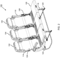
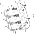
- Each seat within the passenger seat row 100 is configurable, separately or together, between the upright sitting mode shown in FIG. 1 and the bed mode shown in FIG. 3 through an intermediate mode shown in FIG. 2 .
- the seat pan 126 In the upright sitting or TTOL mode, the seat pan 126 is retracted to position the seat pan above the frame 108.
- the seat pan 126 In the bed mode, the seat pan 126 is extended to position the seat pan forward of the frame 108.
- the seat pan 126 may be inclined toward the forward end for cradling comfort and the seat pan translates between the retracted and extended conditions of the seat pan.
- the seat pan 126 attaches to the spaced beam tubes 110.
- the seat pan 126 includes a fixed frame 128 that attaches to the beam tubes and a moving frame 130 that translates relative to the fixed frame, and more particularly, extends forward to achieve the in-flight bed mode and retracts to achieve the TTOL mode.
- the mechanism for attaching the fixed frame 128 to the beam tubes 110 is not limiting, so long as the fixed frame is maintained fixed relative to the seat frame.
- a recess 132 is formed in a front of the backrest 124 and a cushion 134 is removably disposed in the recess 132.
- the cushion 134 When in the TTOL mode, the cushion 134 is positioned in the recess and serves to support the lower back of the seat occupant.
- the cushion 134 When in bed mode, the cushion 134 is removed from the recess 132 and positioned atop the fixed frame 128.
- the length dimension of the cushion 134 is approximately equal to the maximum amount of forward travel of the moving frame 130 or is less than the maximum amount of forward travel.
- the cushion 134 when the moving frame 130 is extended to achieve bed mode, the cushion 134 is removed from the backrest and positioned atop the fixed frame 128 to form a continuous bed formed by the repositioned backrest cushion 134 and the seat pan cushion 136 translated forward with the moving frame 130.
- the cushion in the backrest is used to form part of the bed cushion.
- the cushion 134 can be detached from the backrest and in other embodiments the cushion is pivotally attached to the backrest.
- the backrest cushion may not be removable and instead the infill bed cushion is a separate cushion installed by the flight crew.
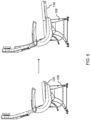
- FIG. 6 shows the conversion from TTOL mode on the left to the bed mode on the right.
- the moving frame 130 When in the TTOL mode the moving frame 130 is positioned above the frame 108.
- the moving frame 130 When in the bed mode, the moving frame 130 is positioned forward of the frame 108, for instance cantilevered.
- the maximum forward travel of the moving frame 130 may be limited by the seat pitch and interference with a forward row or monument.
- the seat pan 126 generally includes the fixed frame 128 and the moving frame 130, and the removable backrest cushion 134 attached atop the fixed frame when the moving frame is moved forward to the extended condition shown in FIG. 7B .
- the moving frame 130 translates horizontally or along its angle of inclination relative to the fixed frame 128.
- Fasteners 138 for instance hook and loop fasteners pairings, function to secure the cushions in place on their respective frame members.
- a hook and loop fastener pairing may also be used to maintain the cushion in the backrest recess.
- the fixed frame 128 generally includes spaced frame members 140 and interconnecting spaced beams 142.
- a plate 144 for instance a foraminous plate for weight savings, is attached atop the spaced beams 142.
- a rack 146 or racks are formed on the inboard side of at least one of the frame members 140 and serves to lock the position of the moving frame relative to the fixed frame 128.
- the rack or racks allow for indexing of the moving frame at discrete positions and at predetermined intervals, for example 1-centimeter intervals, less than 1-centimeter intervals, and greater than 1-centimeter intervals.
- the moving frame 130 generally includes spaced frame members 148, interconnecting spaced beams 150, and a plate 152 positioned atop and attached to the interconnecting spaced beams 150.
- Each of the spaced frame members 148 defines an elongate longitudinal slot 154 receiving one of the interconnecting spaced beams of the fixed frame, such as the forward beams.
- Bosses 156 formed on the outboard sides of the spaced frame members 148 travel along the racks formed on the inboard sides of the spaced frame members of fixed frame to guide translating motion and maintain squareness.
- each passenger seat is equipped with a locking mechanism for locking relative movement of the moving frame relative to the fixed frame.
- the locking mechanism 158 generally includes a Bowden cable 160 coupled at one end to a lever 162 and coupled at an opposing end to a biased lock 164.
- the lock 164 interacts with the rack, for instance having a shape complimentary with the rack to engage therewith.
- the lever 162 is positioned at the forward end of the moving frame 130 to be accessible to the user.
- the locking mechanism 158 is carried by the moving frame 130 considering the moving frame moves and the fixed frame remains stationary.
- actuating e.g., pulling
- the lever 162 translates an inner cable relative to an outer cable of the Bowden cable, thereby pulling the lock 164 to disengage the lock from the rack.
- the inner cable translates relative to the outer cable in the opposite direction to reengage the lock 164 with the rack.
- the lever remains actuated until the moving frame is in the desired frame and then the lever is released.
- the locking mechanism 166 shown in FIG. 11 includes a singular lever 168 operable for actuating all locks in the same row simultaneously.
- the singular lever 168 is an elongate handle positioned below the forward end of the seat pans and is coupled to multiple Bowden cables each coupled to a lock engaging its respective rack. In use, the singular lever 168 is actuated to pull the plurality of internal cables to release the moving frames from their locked positions.
- the singular lever 168 is pulled, the moving frames are pushed toward their retracted positions, and the lever released to lock the moving frames in place.
- Other locking mechanisms are possible and envisioned including electronic actuators which may be passenger or crew controlled, and in some cases networked to be controllable in preparation for a flight condition.
Landscapes
- Engineering & Computer Science (AREA)
- Aviation & Aerospace Engineering (AREA)
- Transportation (AREA)
- Mechanical Engineering (AREA)
- Seats For Vehicles (AREA)
Abstract
Description
- The present disclosure relates generally to aircraft passenger seats, and more particularly to an economy class passenger seat row configured to achieve an in-flight bed mode.
- Passenger aircraft typically include different seating classes. Economy classes are characterized by rows of attached seats and a seat pitch that allows for a minimal amount of backrest recline. Premium classes are characterized by separate seats and a greater seat pitch that allows for maximum seat adjustability. For instance, some super premium seats are configured to achieve a horizontal bed during flight.
- In the case of long-haul flights, a passenger may desire to purchase an entire economy class seat row for privacy and comfort. In other cases, when a flight is not full, passengers may redistribute throughout the cabin to maximize spacing between passengers. In either case, economy class passenger seat rows do not include a provision to sleep.
- Therefore, what is needed is a passenger seat row configured with an in-flight bed mode.
- Broadly speaking, the present disclosure provides economy class passenger seat rows configured with an in-flight bed mode.
- To achieve the foregoing and other advantages, the inventive aspects disclosed herein are directed to a passenger seat row including at least two passenger seats attached to a common frame. Each passenger seat includes a backrest forming a recess on a front of the backrest, a cushion removably disposed in the recess, and a seat pan including a fixed frame and a moving frame movably coupled to the fixed frame. In a taxi, takeoff and landing (TTOL) mode of the passenger seat row the moving frame of each of the at least two passenger seats is retracted relative to its respective fixed frame and the cushion is disposed in the recess, and in a bed mode of the passenger seat row the moving frame of each of the at least two passenger seats is extended relative to its fixed frame and the cushion is positioned atop its respective fixed frame.
- In some embodiments, a length dimension of the cushion is substantially equal to an amount of travel of the moving frame relative to the fixed frame.
- In some embodiments, the moving frame translates relative to the fixed frame as the moving frame extends and retracts.
- In some embodiments, the fixed frame comprises spaced frame members interconnected by spaced beams and a foraminous plate attached atop the spaced beams, at least one of the spaced frame members defining a rack on an inboard side thereof, and the moving frame comprises spaced frame members interconnected by spaced beams and a foraminous plate attached atop the spaced beams, each of the spaced frame members defining an elongate slot. A forward beam of the spaced beams of the fixed frame is disposed in the elongate slot of each of the spaced frame members of the moving frame for guiding movement of the moving frame relative to the fixed frame.
- In some embodiments, the seat row further includes a locking mechanism associated with each of the at least two passenger seats for locking relative motion between the moving frame and the fixed frame.
- In some embodiments, the locking mechanism includes a lock configured to interact with the rack on at least one of the frame members of the fixed frame to lock a position of the moving frame relative to the fixed frame, a lever positioned on the moving frame, and a Bowden cable coupled to each of the lock and the lever. In use, pulling the lever causes an inner cable of the Bowden cable to disengage the lock from the rack to permit movement of the moving frame relative to the fixed frame.
- In some embodiments, the seat row further includes hook and loop fasteners positioned in the recess, on a bottom side of the cushion, and atop the foraminous plate of at least one of the fixed frame and the moving frame, wherein in use, the hook and loop fasteners secure the cushion in the recess and atop at least one of the fixed frame and the moving frame.
- In some embodiments, when in the TTOL mode the moving frame is positioned above the common frame and when in the bed mode the moving frame is positioned forward of the common frame.
- In some embodiments, the common frame includes spaced beam tubes supporting the fixed frame of the at least two passenger seats, spreaders forming legs for attachment to a floor, and at least one armrest.
- In some embodiments, the passenger seat row includes at least three passenger seats.
- In some embodiments, the passenger seat row includes a locking mechanism for locking relative motion of each of the moving frames relative to the respective fixed frames. The locking mechanism includes configured to interact with the racks on at least one of the frame members of each of the fixed frames to lock a position of the moving frames relative to the fixed frames, a singular lever positioned under a forward end of the moving frames, and Bowden cables coupled to each of the locks and to the singular lever. In use, pulling the singular lever causes an inner cable of the Bowden cables to disengage the locks from the racks simultaneously to permit movement of the moving frames relative to the fixed frames.
- The inventive aspects disclosed herein are further directed to an aircraft passenger seat including a frame, a backrest attached to the frame and forming a recess on a front of the backrest, a cushion removably disposed in the recess, and a seat pan attached to the frame and including a fixed frame and a moving frame movably coupled to the fixed frame. In a TTOL mode of the aircraft passenger seat the moving frame is retracted relative to the fixed frame and the cushion is disposed in the recess, and in a bed mode of the aircraft passenger seat the moving frame is extended relative to the fixed frame and the cushion is positioned atop the fixed frame.
- In some embodiments, the fixed frame includes spaced frame members interconnected by spaced beams and a foraminous plate attached atop the spaced beams, at least one of the spaced frame members defining a rack on an inboard side thereof, and the moving frame includes spaced frame members interconnected by spaced beams and a foraminous plate attached atop the spaced beams, each of the spaced frame members defining an elongate slot receiving of the spaced beams of the fixed frame.
- In some embodiments, the passenger seat further includes a locking mechanism for locking a position of the moving frame relative to the fixed frame. The locking mechanism includes a lock configured to interact with the rack on at least one of the frame members of the fixed frame to lock a position of the moving frame relative to the fixed frame, a lever positioned on the moving frame, and a Bowden cable coupled to each of the lock and the lever, wherein in use, pulling the lever causes an inner cable of the Bowden cable to disengage the lock from the rack to permit movement of the moving frame relative to the fixed frame.
- Implementations of the inventive concepts disclosed herein may be better understood when consideration is given to the following detailed description thereof. Such description makes reference to the included drawings, which are not necessarily to scale, and in which some features may be exaggerated, and some features may be omitted or may be represented schematically in the interest of clarity. Like reference numbers in the drawings may represent and refer to the same or similar element, feature, or function. In the drawings:
-
FIG. 1 shows an isometric view of a passenger seat row according to the present disclosure and in a taxi, takeoff and landing (TTOL) mode; -
FIG. 2 shows the passenger seat row ofFIG. 1 in a partially converted mode; -
FIG. 3 shows the passenger seat row ofFIG. 1 in an in-flight bed mode; -
FIG. 4 shows a detailed view of seat pan attachment to a frame; -
FIG. 5 shows a side view of an individual passenger seat in bed mode and the location of the bed cushion in the backrest; -
FIG. 6 shows a side elevation view of a passenger seat converted from TTOL mode to bed mode; -
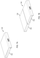
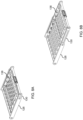
FIGS. 7A and 7B show the seat pan in TTOL mode and bed mode, respectively; -
FIGS. 8A and 8B show the seat pan in TTOL mode and bed mode, respectively, and with the cushions removed for clarity; -
FIG. 9A shows the fixed frame of the seat pan; -
FIG. 9B shows an exploded view of the fixed frame of the seat pan; -
FIG. 9C shows an inside view of a frame member of the fixed frame of the seat pan; -
FIG. 9D shows a toother rack of the frame member ofFIG. 9C ; -
FIG. 10A shows a moving frame of the seat pan; -
FIG. 10B shows an exploded view of the moving frame of the seat pan; and -
FIG. 11 shows an isometric view of a seat row including a single lever to for actuating seat pan translation. - The description set forth below in connection with the appended drawings is intended to be a description of various, illustrative embodiments of the disclosed subject matter. Specific features and functionalities are described in connection with each illustrative embodiment; however, it will be apparent to those skilled in the art that the disclosed embodiments may be practiced without each of those specific features and functionalities. The aspects, features and functions described below in connection with one embodiment are intended to be applicable to the other embodiments described below except where expressly stated or where an aspect, feature or function is incompatible with an embodiment.
- Broadly speaking, the present disclosure provides embodiments of passenger seats and passenger seat rows configured to adjust between an upright sitting mode and a bed mode. When implemented in an aircraft, the upright sitting mode may correspond to a taxi, takeoff and landing mode in which the seat pan is retracted and the backrest is fully upright or reclined. When the seat embodiments are equipped with backrest recline, the seat pan motions described herein may be independent of the backrest recline mechanism and other mechanisms of the seat. When implemented as a passenger seat row, the row includes at least two, and preferably at least three laterally adjacent passenger seats to provide an adequate bed length.
- Referring to
FIGS. 1-4 , thepassenger seat row 100 shown includes three laterallyadjacent passenger seats common frame 108. As used herein, the term "common" means shared and not ordinary, and common may mean at least one of the elements of theframe 108 is shared by at least two of the seats. Theframe 108 generally includes spacedbeam tubes 110 extending the length of the seat row,spreaders 112 positioned at the lateral extents of the seat row and between adjacent seats, backrest frames 114 pivotally attached to the spreaders or another frame element, andarmrests 116 positioned at the lateral extents of the seat row and between adjacent seats. Thearmrests 116 are preferably configured to pivot between stowed and deployed positions to be stowed during boarding, deplaning, and when the seat row is configured for bed mode. The spreaders may form or be attached tolegs 118 for attachment to the floor, such as by way oftrack fasteners 120. In some embodiments, theframe 108 includes aluggage retention bar 122. - Each
passenger seat backrest 124 and aseat pan assembly 126, also referred to herein as the seat pan. Each seat within thepassenger seat row 100 is configurable, separately or together, between the upright sitting mode shown inFIG. 1 and the bed mode shown inFIG. 3 through an intermediate mode shown inFIG. 2 . In the upright sitting or TTOL mode, theseat pan 126 is retracted to position the seat pan above theframe 108. In the bed mode, theseat pan 126 is extended to position the seat pan forward of theframe 108. Theseat pan 126 may be inclined toward the forward end for cradling comfort and the seat pan translates between the retracted and extended conditions of the seat pan. - With specific reference to
FIG. 4 , theseat pan 126 attaches to the spacedbeam tubes 110. As discussed in detail below, theseat pan 126 includes a fixedframe 128 that attaches to the beam tubes and a movingframe 130 that translates relative to the fixed frame, and more particularly, extends forward to achieve the in-flight bed mode and retracts to achieve the TTOL mode. The mechanism for attaching the fixedframe 128 to thebeam tubes 110 is not limiting, so long as the fixed frame is maintained fixed relative to the seat frame. - Referring to
FIG. 5 , arecess 132 is formed in a front of thebackrest 124 and acushion 134 is removably disposed in therecess 132. When in the TTOL mode, thecushion 134 is positioned in the recess and serves to support the lower back of the seat occupant. When in bed mode, thecushion 134 is removed from therecess 132 and positioned atop the fixedframe 128. In some embodiments, the length dimension of thecushion 134 is approximately equal to the maximum amount of forward travel of the movingframe 130 or is less than the maximum amount of forward travel. As such, when the movingframe 130 is extended to achieve bed mode, thecushion 134 is removed from the backrest and positioned atop the fixedframe 128 to form a continuous bed formed by the repositionedbackrest cushion 134 and theseat pan cushion 136 translated forward with the movingframe 130. Thus, the cushion in the backrest is used to form part of the bed cushion. In some embodiments, thecushion 134 can be detached from the backrest and in other embodiments the cushion is pivotally attached to the backrest. In an alternative embodiment, the backrest cushion may not be removable and instead the infill bed cushion is a separate cushion installed by the flight crew. -
FIG. 6 shows the conversion from TTOL mode on the left to the bed mode on the right. When in the TTOL mode the movingframe 130 is positioned above theframe 108. When in the bed mode, the movingframe 130 is positioned forward of theframe 108, for instance cantilevered. The maximum forward travel of the movingframe 130 may be limited by the seat pitch and interference with a forward row or monument. - Referring to
FIGS. 7A and 7B , theseat pan 126 generally includes the fixedframe 128 and the movingframe 130, and theremovable backrest cushion 134 attached atop the fixed frame when the moving frame is moved forward to the extended condition shown inFIG. 7B . Referring toFIGS. 8A and 8B , the movingframe 130 translates horizontally or along its angle of inclination relative to the fixedframe 128.Fasteners 138, for instance hook and loop fasteners pairings, function to secure the cushions in place on their respective frame members. A hook and loop fastener pairing may also be used to maintain the cushion in the backrest recess. - Referring to
FIGS. 9A-9D , the fixedframe 128 generally includes spacedframe members 140 and interconnecting spaced beams 142. Aplate 144, for instance a foraminous plate for weight savings, is attached atop the spaced beams 142. Arack 146 or racks are formed on the inboard side of at least one of theframe members 140 and serves to lock the position of the moving frame relative to the fixedframe 128. In some embodiments, the rack or racks allow for indexing of the moving frame at discrete positions and at predetermined intervals, for example 1-centimeter intervals, less than 1-centimeter intervals, and greater than 1-centimeter intervals. - Referring to
FIGS. 10A and 10B , the movingframe 130 generally includes spacedframe members 148, interconnecting spacedbeams 150, and aplate 152 positioned atop and attached to the interconnecting spaced beams 150. Each of the spacedframe members 148 defines an elongatelongitudinal slot 154 receiving one of the interconnecting spaced beams of the fixed frame, such as the forward beams.Bosses 156 formed on the outboard sides of the spacedframe members 148 travel along the racks formed on the inboard sides of the spaced frame members of fixed frame to guide translating motion and maintain squareness. - In some embodiments, each passenger seat is equipped with a locking mechanism for locking relative movement of the moving frame relative to the fixed frame. With continued reference to
FIGS. 10A and 10B , thelocking mechanism 158 generally includes aBowden cable 160 coupled at one end to alever 162 and coupled at an opposing end to abiased lock 164. Thelock 164 interacts with the rack, for instance having a shape complimentary with the rack to engage therewith. Thelever 162 is positioned at the forward end of the movingframe 130 to be accessible to the user. Thelocking mechanism 158 is carried by the movingframe 130 considering the moving frame moves and the fixed frame remains stationary. In use, actuating (e.g., pulling) thelever 162 translates an inner cable relative to an outer cable of the Bowden cable, thereby pulling thelock 164 to disengage the lock from the rack. When the lever is released, the inner cable translates relative to the outer cable in the opposite direction to reengage thelock 164 with the rack. To move the movingframe 130 relative to the fixed frame, the lever remains actuated until the moving frame is in the desired frame and then the lever is released. - Referring to
FIG. 11 , whereas the locking mechanism shown inFIGS. 10A and 10B is associated with each passenger seat, thelocking mechanism 166 shown inFIG. 11 includes asingular lever 168 operable for actuating all locks in the same row simultaneously. In some embodiment, thesingular lever 168 is an elongate handle positioned below the forward end of the seat pans and is coupled to multiple Bowden cables each coupled to a lock engaging its respective rack. In use, thesingular lever 168 is actuated to pull the plurality of internal cables to release the moving frames from their locked positions. To retract the moving frames, i.e., return the moving frame toward their TTOL positions, thesingular lever 168 is pulled, the moving frames are pushed toward their retracted positions, and the lever released to lock the moving frames in place. Other locking mechanisms are possible and envisioned including electronic actuators which may be passenger or crew controlled, and in some cases networked to be controllable in preparation for a flight condition. - While the foregoing description provides embodiments of the invention by way of example only, it is envisioned that other embodiments may perform similar functions and/or achieve similar results. Any and all such equivalent embodiments and examples are within the scope of the present invention and are intended to be covered by the appended claims.
Claims (15)
- A passenger seat row; comprising:at least two passenger seats (102, 104, 106) attached to a common frame (108), each of the at least two passenger seats comprising:a backrest (124) forming a recess (132) on a front of the backrest;a cushion (134) removably disposed in the recess; anda seat pan (126) including a fixed frame (128) and a moving frame (130) movably coupled to the fixed frame;wherein in a taxi, takeoff and landing, TTOL, mode of the passenger seat row, the moving frame of each of the at least two passenger seats is retracted relative to its respective fixed frame and the cushion is disposed in the recess; andwherein in a bed mode of the passenger seat row, the moving frame of each of the at least two passenger seats is extended relative to its fixed frame and the cushion is positioned atop its respective fixed frame.
- The passenger seat row according to claim 1, wherein a length dimension of the cushion (134) is substantially equal to an amount of travel of the moving frame (130) relative to the fixed frame (128).
- The passenger seat row according to claim 1 or 2, wherein the moving frame (130) translates relative to the fixed frame (128) as the moving frame extends and retracts.
- The passenger seat row according to claim 1, 2 or 3, wherein:the fixed frame (128) comprises spaced frame members (140) interconnected by spaced beams (142) and a foraminous plate attached atop the spaced beams, at least one of the spaced frame members defining a rack (146) on an inboard side thereof; andthe moving frame (130) comprises spaced frame members (148) interconnected by spaced beams (150) and a foraminous plate attached atop the spaced beams, each of the spaced frame members defining an elongate slot (154);wherein a forward beam of the spaced beams of the fixed frame is disposed in the elongate slot of each of the spaced frame members of the moving frame for guiding movement of the moving frame relative to the fixed frame.
- The passenger seat row according to any preceding claim, further comprising a locking mechanism (166) associated with each of the at least two passenger seats (102, 104, 106) for locking relative motion between the moving frame (130) and the fixed frame (128).
- The passenger seat row according to claim 5, wherein the locking mechanism (166) comprises:a lock (164) configured to interact with the rack on at least one of the frame members (140) of the fixed frame (128) to lock a position of the moving frame (130) relative to the fixed frame;a lever (168) positioned on the moving frame; anda Bowden cable (160) coupled to each of the lock and the lever, wherein in use, pulling the lever causes an inner cable of the Bowden cable to disengage the lock from the rack to permit movement of the moving frame relative to the fixed frame.
- The passenger seat row according to any preceding claim, further comprising hook and look fasteners positioned in the recess (132), on a bottom side of the cushion (134), and atop the foraminous plate of at least one of the fixed frame (128) and the moving frame (130), wherein in use, the hook and loop fasteners secure the cushion in the recess and atop at least one of the fixed frame and the moving frame.
- The passenger seat row according to any preceding claim, wherein:when in the TTOL mode, the moving frame (130) is positioned above the common frame (108); andwhen in the bed mode, the moving frame is positioned forward of the common frame.
- The passenger seat row according to any preceding claim, wherein the common frame (108) comprises:spaced beam tubes (110) supporting the fixed frame (128) of the at least two passenger seats (102, 104, 106);spreaders (112) forming legs (118) for attachment to a floor; andat least one armrest (116).
- The passenger seat row according to any preceding claim, comprising at least three passenger seats (102, 104, 106).
- The passenger seat row according to any of claims 1 to 4, comprising a locking mechanism (166) for locking relative motion of each of the moving frames (130) relative to the respective fixed frames (128), the locking mechanism comprising:locks (164) configured to interact with the racks (146) on at least one of the frame members (140) of each of the fixed frames (128) to lock a position of the moving frames relative to the fixed frames;a singular lever (168) positioned under a forward end of the moving frames; andBowden cables coupled to each of the locks and to the singular lever, wherein in use, pulling the singular lever causes an inner cable of the Bowden cables to disengage the locks from the racks simultaneously to permit movement of the moving frames relative to the fixed frames.
- An aircraft passenger seat (102, 104, 106), comprising:a frame (108);a backrest (124) attached to the frame, the backrest forming a recess (132) on a front of the backrest;a cushion (134) removably disposed in the recess; anda seat pan (126) attached to the frame, the seat pan including a fixed frame (128) and a moving frame (130) movably coupled to the fixed frame;wherein in a taxi, takeoff and landing, TTOL, mode of the aircraft passenger seat, the moving frame is retracted relative to the fixed frame and the cushion is disposed in the recess; andwherein in a bed mode of the aircraft passenger seat, the moving frame is extended relative to the fixed frame and the cushion is positioned atop the fixed frame.
- The aircraft passenger seat according to claim 12, wherein:the fixed frame (128) comprises spaced frame members (140) interconnected by spaced beams (142) and a foraminous plate attached atop the spaced beams, at least one of the spaced frame members defining a rack (146) on an inboard side thereof; andthe moving frame (130) comprises spaced frame members (148) interconnected by spaced beams (150) and a foraminous plate attached atop the spaced beams, each of the spaced frame members defining an elongate slot (154);wherein a forward beam of the spaced beams of the fixed frame is disposed in the elongate slot of each of the spaced frame members of the moving frame for guiding movement of the moving frame relative to the fixed frame.
- The aircraft passenger seat according to claim 12 or 13, further comprising a locking mechanism (166) for locking relative motion between the moving frame (130) and the fixed frame (128), the locking mechanism comprising:a lock (164) configured to interact with the rack (146) on at least one of the frame members of the fixed frame to lock a position of the moving frame relative to the fixed frame;a lever (168) positioned on the moving frame; anda Bowden cable coupled to each of the lock and the lever, wherein in use, pulling the lever causes an inner cable of the Bowden cable to disengage the lock from the rack to permit movement of the moving frame relative to the fixed frame.
- The aircraft passenger seat according to any of claims 12 to 14, wherein:the moving frame (130) translates relative to the fixed frame (128);when in the TTOL mode, the moving frame is positioned above the frame; andwhen in the bed mode, the moving frame is positioned forward of the frame.
Applications Claiming Priority (2)
| Application Number | Priority Date | Filing Date | Title |
|---|---|---|---|
| IN202241031495 | 2022-06-01 | ||
| US17/872,874 US12187437B2 (en) | 2022-06-01 | 2022-07-25 | Economy class passenger seat with bed mode and removable cushion |
Publications (2)
| Publication Number | Publication Date |
|---|---|
| EP4286277A1 true EP4286277A1 (en) | 2023-12-06 |
| EP4286277B1 EP4286277B1 (en) | 2025-08-13 |
Family
ID=86605728
Family Applications (1)
| Application Number | Title | Priority Date | Filing Date |
|---|---|---|---|
| EP23175812.9A Active EP4286277B1 (en) | 2022-06-01 | 2023-05-26 | Economy class passenger seat row with bed mode |
Country Status (1)
| Country | Link |
|---|---|
| EP (1) | EP4286277B1 (en) |
Citations (3)
| Publication number | Priority date | Publication date | Assignee | Title |
|---|---|---|---|---|
| JPS5527435U (en) * | 1978-08-11 | 1980-02-22 | ||
| US20140265513A1 (en) * | 2011-12-16 | 2014-09-18 | Trevor Edouard Lambert | Vehicle Seat |
| EP3078594B1 (en) * | 2015-03-30 | 2018-08-01 | Aviointeriors S.p.A. | Improved differently configurable vehicle seat |
-
2023
- 2023-05-26 EP EP23175812.9A patent/EP4286277B1/en active Active
Patent Citations (3)
| Publication number | Priority date | Publication date | Assignee | Title |
|---|---|---|---|---|
| JPS5527435U (en) * | 1978-08-11 | 1980-02-22 | ||
| US20140265513A1 (en) * | 2011-12-16 | 2014-09-18 | Trevor Edouard Lambert | Vehicle Seat |
| EP3078594B1 (en) * | 2015-03-30 | 2018-08-01 | Aviointeriors S.p.A. | Improved differently configurable vehicle seat |
Also Published As
| Publication number | Publication date |
|---|---|
| EP4286277B1 (en) | 2025-08-13 |
Similar Documents
| Publication | Publication Date | Title |
|---|---|---|
| US12187437B2 (en) | Economy class passenger seat with bed mode and removable cushion | |
| US5131607A (en) | Extendable and retractable aircraft seat assembly | |
| EP1571037B1 (en) | A seating system and a passenger accommodation unit for a vehicle | |
| US11040775B2 (en) | Seat assemblies, such as for use in aircraft, and associated systems and methods | |
| US10953987B2 (en) | Aircraft interior configuration with flexible use space | |
| US9545999B2 (en) | Seating arrangement | |
| EP3689748B1 (en) | Deployable infill assembly and passenger seat construction | |
| EP3680173B1 (en) | Passenger seat reconfigurable for seating or storage | |
| US20230331389A1 (en) | Configurable cabin attendant seat | |
| US12269598B2 (en) | Economy class passenger seat row convertible to bunk beds | |
| US8851568B2 (en) | Retractable passenger seat | |
| US20050184566A1 (en) | Aircraft passenger seat row | |
| EP4286277B1 (en) | Economy class passenger seat row with bed mode | |
| US12049320B2 (en) | Passenger seating assembly with swinging seatpan for increased passenger egress space | |
| US12157574B2 (en) | Interior layout of an aircraft cabin and associated method | |
| EP4592179A1 (en) | Passenger seat with coupled linkage and cradled recline motion | |
| US12351317B2 (en) | Row of passenger seats convertible to a bed | |
| US12459650B2 (en) | Converting economy seat to full flat bed by dropping seat back frame | |
| EP4253238A1 (en) | Integrated meal tray for passenger seat with low-profile pull-style latch | |
| EP4506252A1 (en) | Row of passenger seats convertible to a bed | |
| EP4480822A1 (en) | Converting economy seat to full flat bed by dropping seat back frame | |
| EP4015385B1 (en) | Aircraft passenger seat row with cabin attendant seat | |
| EP4223642A1 (en) | Passenger seating assembly with swinging seatpan for increased passenger egress space | |
| WO2025184692A1 (en) | Aircraft seating arrangements | |
| HK1076432B (en) | A seating system and a passenger accommodation unit for a vehicle |
Legal Events
| Date | Code | Title | Description |
|---|---|---|---|
| PUAI | Public reference made under article 153(3) epc to a published international application that has entered the european phase |
Free format text: ORIGINAL CODE: 0009012 |
|
| STAA | Information on the status of an ep patent application or granted ep patent |
Free format text: STATUS: THE APPLICATION HAS BEEN PUBLISHED |
|
| AK | Designated contracting states |
Kind code of ref document: A1 Designated state(s): AL AT BE BG CH CY CZ DE DK EE ES FI FR GB GR HR HU IE IS IT LI LT LU LV MC ME MK MT NL NO PL PT RO RS SE SI SK SM TR |
|
| STAA | Information on the status of an ep patent application or granted ep patent |
Free format text: STATUS: REQUEST FOR EXAMINATION WAS MADE |
|
| 17P | Request for examination filed |
Effective date: 20240605 |
|
| RBV | Designated contracting states (corrected) |
Designated state(s): AL AT BE BG CH CY CZ DE DK EE ES FI FR GB GR HR HU IE IS IT LI LT LU LV MC ME MK MT NL NO PL PT RO RS SE SI SK SM TR |
|
| GRAP | Despatch of communication of intention to grant a patent |
Free format text: ORIGINAL CODE: EPIDOSNIGR1 |
|
| STAA | Information on the status of an ep patent application or granted ep patent |
Free format text: STATUS: GRANT OF PATENT IS INTENDED |
|
| INTG | Intention to grant announced |
Effective date: 20250321 |
|
| GRAS | Grant fee paid |
Free format text: ORIGINAL CODE: EPIDOSNIGR3 |
|
| GRAA | (expected) grant |
Free format text: ORIGINAL CODE: 0009210 |
|
| STAA | Information on the status of an ep patent application or granted ep patent |
Free format text: STATUS: THE PATENT HAS BEEN GRANTED |
|
| RIN1 | Information on inventor provided before grant (corrected) |
Inventor name: KODATI, SAMBASIVA RAO Inventor name: GUDLA, CHANDRA SEKHAR |
|
| AK | Designated contracting states |
Kind code of ref document: B1 Designated state(s): AL AT BE BG CH CY CZ DE DK EE ES FI FR GB GR HR HU IE IS IT LI LT LU LV MC ME MK MT NL NO PL PT RO RS SE SI SK SM TR |
|
| REG | Reference to a national code |
Ref country code: GB Ref legal event code: FG4D |
|
| REG | Reference to a national code |
Ref country code: CH Ref legal event code: EP |
|
| REG | Reference to a national code |
Ref country code: DE Ref legal event code: R096 Ref document number: 602023005619 Country of ref document: DE |
|
| REG | Reference to a national code |
Ref country code: IE Ref legal event code: FG4D |
|
| PG25 | Lapsed in a contracting state [announced via postgrant information from national office to epo] |
Ref country code: IS Free format text: LAPSE BECAUSE OF FAILURE TO SUBMIT A TRANSLATION OF THE DESCRIPTION OR TO PAY THE FEE WITHIN THE PRESCRIBED TIME-LIMIT Effective date: 20251213 |
|
| PG25 | Lapsed in a contracting state [announced via postgrant information from national office to epo] |
Ref country code: NO Free format text: LAPSE BECAUSE OF FAILURE TO SUBMIT A TRANSLATION OF THE DESCRIPTION OR TO PAY THE FEE WITHIN THE PRESCRIBED TIME-LIMIT Effective date: 20251113 |
|
| REG | Reference to a national code |
Ref country code: LT Ref legal event code: MG9D |
|
| PG25 | Lapsed in a contracting state [announced via postgrant information from national office to epo] |
Ref country code: PT Free format text: LAPSE BECAUSE OF FAILURE TO SUBMIT A TRANSLATION OF THE DESCRIPTION OR TO PAY THE FEE WITHIN THE PRESCRIBED TIME-LIMIT Effective date: 20251215 |
|
| PG25 | Lapsed in a contracting state [announced via postgrant information from national office to epo] |
Ref country code: FI Free format text: LAPSE BECAUSE OF FAILURE TO SUBMIT A TRANSLATION OF THE DESCRIPTION OR TO PAY THE FEE WITHIN THE PRESCRIBED TIME-LIMIT Effective date: 20250813 |
|
| PG25 | Lapsed in a contracting state [announced via postgrant information from national office to epo] |
Ref country code: HR Free format text: LAPSE BECAUSE OF FAILURE TO SUBMIT A TRANSLATION OF THE DESCRIPTION OR TO PAY THE FEE WITHIN THE PRESCRIBED TIME-LIMIT Effective date: 20250813 Ref country code: NL Free format text: LAPSE BECAUSE OF FAILURE TO SUBMIT A TRANSLATION OF THE DESCRIPTION OR TO PAY THE FEE WITHIN THE PRESCRIBED TIME-LIMIT Effective date: 20250813 |
|
| PG25 | Lapsed in a contracting state [announced via postgrant information from national office to epo] |
Ref country code: GR Free format text: LAPSE BECAUSE OF FAILURE TO SUBMIT A TRANSLATION OF THE DESCRIPTION OR TO PAY THE FEE WITHIN THE PRESCRIBED TIME-LIMIT Effective date: 20251114 |
|
| PG25 | Lapsed in a contracting state [announced via postgrant information from national office to epo] |
Ref country code: SE Free format text: LAPSE BECAUSE OF FAILURE TO SUBMIT A TRANSLATION OF THE DESCRIPTION OR TO PAY THE FEE WITHIN THE PRESCRIBED TIME-LIMIT Effective date: 20250813 |
|
| PG25 | Lapsed in a contracting state [announced via postgrant information from national office to epo] |
Ref country code: LV Free format text: LAPSE BECAUSE OF FAILURE TO SUBMIT A TRANSLATION OF THE DESCRIPTION OR TO PAY THE FEE WITHIN THE PRESCRIBED TIME-LIMIT Effective date: 20250813 |
|
| PG25 | Lapsed in a contracting state [announced via postgrant information from national office to epo] |
Ref country code: PL Free format text: LAPSE BECAUSE OF FAILURE TO SUBMIT A TRANSLATION OF THE DESCRIPTION OR TO PAY THE FEE WITHIN THE PRESCRIBED TIME-LIMIT Effective date: 20250813 Ref country code: BG Free format text: LAPSE BECAUSE OF FAILURE TO SUBMIT A TRANSLATION OF THE DESCRIPTION OR TO PAY THE FEE WITHIN THE PRESCRIBED TIME-LIMIT Effective date: 20250813 |
|
| PG25 | Lapsed in a contracting state [announced via postgrant information from national office to epo] |
Ref country code: RS Free format text: LAPSE BECAUSE OF FAILURE TO SUBMIT A TRANSLATION OF THE DESCRIPTION OR TO PAY THE FEE WITHIN THE PRESCRIBED TIME-LIMIT Effective date: 20251113 |
|
| PG25 | Lapsed in a contracting state [announced via postgrant information from national office to epo] |
Ref country code: ES Free format text: LAPSE BECAUSE OF FAILURE TO SUBMIT A TRANSLATION OF THE DESCRIPTION OR TO PAY THE FEE WITHIN THE PRESCRIBED TIME-LIMIT Effective date: 20250813 |
|
| REG | Reference to a national code |
Ref country code: AT Ref legal event code: MK05 Ref document number: 1824437 Country of ref document: AT Kind code of ref document: T Effective date: 20250813 |
|
| PG25 | Lapsed in a contracting state [announced via postgrant information from national office to epo] |
Ref country code: SM Free format text: LAPSE BECAUSE OF FAILURE TO SUBMIT A TRANSLATION OF THE DESCRIPTION OR TO PAY THE FEE WITHIN THE PRESCRIBED TIME-LIMIT Effective date: 20250813 |
|
| PG25 | Lapsed in a contracting state [announced via postgrant information from national office to epo] |
Ref country code: DK Free format text: LAPSE BECAUSE OF FAILURE TO SUBMIT A TRANSLATION OF THE DESCRIPTION OR TO PAY THE FEE WITHIN THE PRESCRIBED TIME-LIMIT Effective date: 20250813 |
|
| PG25 | Lapsed in a contracting state [announced via postgrant information from national office to epo] |
Ref country code: AT Free format text: LAPSE BECAUSE OF FAILURE TO SUBMIT A TRANSLATION OF THE DESCRIPTION OR TO PAY THE FEE WITHIN THE PRESCRIBED TIME-LIMIT Effective date: 20250813 |
|
| PG25 | Lapsed in a contracting state [announced via postgrant information from national office to epo] |
Ref country code: IT Free format text: LAPSE BECAUSE OF FAILURE TO SUBMIT A TRANSLATION OF THE DESCRIPTION OR TO PAY THE FEE WITHIN THE PRESCRIBED TIME-LIMIT Effective date: 20250813 |
|
| PG25 | Lapsed in a contracting state [announced via postgrant information from national office to epo] |
Ref country code: CZ Free format text: LAPSE BECAUSE OF FAILURE TO SUBMIT A TRANSLATION OF THE DESCRIPTION OR TO PAY THE FEE WITHIN THE PRESCRIBED TIME-LIMIT Effective date: 20250813 |
|
| PG25 | Lapsed in a contracting state [announced via postgrant information from national office to epo] |
Ref country code: SK Free format text: LAPSE BECAUSE OF FAILURE TO SUBMIT A TRANSLATION OF THE DESCRIPTION OR TO PAY THE FEE WITHIN THE PRESCRIBED TIME-LIMIT Effective date: 20250813 Ref country code: EE Free format text: LAPSE BECAUSE OF FAILURE TO SUBMIT A TRANSLATION OF THE DESCRIPTION OR TO PAY THE FEE WITHIN THE PRESCRIBED TIME-LIMIT Effective date: 20250813 |