EP4286128B1 - Apparatus and method for processing material in a hopper - Google Patents
Apparatus and method for processing material in a hopper Download PDFInfo
- Publication number
- EP4286128B1 EP4286128B1 EP23174837.7A EP23174837A EP4286128B1 EP 4286128 B1 EP4286128 B1 EP 4286128B1 EP 23174837 A EP23174837 A EP 23174837A EP 4286128 B1 EP4286128 B1 EP 4286128B1
- Authority
- EP
- European Patent Office
- Prior art keywords
- process fluid
- internal volume
- permeable
- incoherent
- plastics
- Prior art date
- Legal status (The legal status is an assumption and is not a legal conclusion. Google has not performed a legal analysis and makes no representation as to the accuracy of the status listed.)
- Active
Links
Images


Classifications
-
- B—PERFORMING OPERATIONS; TRANSPORTING
- B29—WORKING OF PLASTICS; WORKING OF SUBSTANCES IN A PLASTIC STATE IN GENERAL
- B29B—PREPARATION OR PRETREATMENT OF THE MATERIAL TO BE SHAPED; MAKING GRANULES OR PREFORMS; RECOVERY OF PLASTICS OR OTHER CONSTITUENTS OF WASTE MATERIAL CONTAINING PLASTICS
- B29B13/00—Conditioning or physical treatment of the material to be shaped
- B29B13/02—Conditioning or physical treatment of the material to be shaped by heating
-
- B—PERFORMING OPERATIONS; TRANSPORTING
- B29—WORKING OF PLASTICS; WORKING OF SUBSTANCES IN A PLASTIC STATE IN GENERAL
- B29B—PREPARATION OR PRETREATMENT OF THE MATERIAL TO BE SHAPED; MAKING GRANULES OR PREFORMS; RECOVERY OF PLASTICS OR OTHER CONSTITUENTS OF WASTE MATERIAL CONTAINING PLASTICS
- B29B13/00—Conditioning or physical treatment of the material to be shaped
- B29B13/06—Conditioning or physical treatment of the material to be shaped by drying
- B29B13/065—Conditioning or physical treatment of the material to be shaped by drying of powder or pellets
-
- F—MECHANICAL ENGINEERING; LIGHTING; HEATING; WEAPONS; BLASTING
- F26—DRYING
- F26B—DRYING SOLID MATERIALS OR OBJECTS BY REMOVING LIQUID THEREFROM
- F26B17/00—Machines or apparatus for drying materials in loose, plastic, or fluidised form, e.g. granules, staple fibres, with progressive movement
- F26B17/12—Machines or apparatus for drying materials in loose, plastic, or fluidised form, e.g. granules, staple fibres, with progressive movement with movement performed solely by gravity, i.e. the material moving through a substantially vertical drying enclosure, e.g. shaft
- F26B17/14—Machines or apparatus for drying materials in loose, plastic, or fluidised form, e.g. granules, staple fibres, with progressive movement with movement performed solely by gravity, i.e. the material moving through a substantially vertical drying enclosure, e.g. shaft the materials moving through a counter-current of gas
- F26B17/1408—Machines or apparatus for drying materials in loose, plastic, or fluidised form, e.g. granules, staple fibres, with progressive movement with movement performed solely by gravity, i.e. the material moving through a substantially vertical drying enclosure, e.g. shaft the materials moving through a counter-current of gas the gas being supplied and optionally extracted through ducts extending into the moving stack of material
- F26B17/1425—Machines or apparatus for drying materials in loose, plastic, or fluidised form, e.g. granules, staple fibres, with progressive movement with movement performed solely by gravity, i.e. the material moving through a substantially vertical drying enclosure, e.g. shaft the materials moving through a counter-current of gas the gas being supplied and optionally extracted through ducts extending into the moving stack of material the ducts being perforated and arranged vertically
-
- F—MECHANICAL ENGINEERING; LIGHTING; HEATING; WEAPONS; BLASTING
- F26—DRYING
- F26B—DRYING SOLID MATERIALS OR OBJECTS BY REMOVING LIQUID THEREFROM
- F26B25/00—Details of general application not covered by group F26B21/00 or F26B23/00
- F26B25/005—Treatment of dryer exhaust gases
- F26B25/007—Dust filtering; Exhaust dust filters
-
- F—MECHANICAL ENGINEERING; LIGHTING; HEATING; WEAPONS; BLASTING
- F26—DRYING
- F26B—DRYING SOLID MATERIALS OR OBJECTS BY REMOVING LIQUID THEREFROM
- F26B3/00—Drying solid materials or objects by processes involving the application of heat
- F26B3/02—Drying solid materials or objects by processes involving the application of heat by convection, i.e. heat being conveyed from a heat source to the materials or objects to be dried by a gas or vapour, e.g. air
- F26B3/06—Drying solid materials or objects by processes involving the application of heat by convection, i.e. heat being conveyed from a heat source to the materials or objects to be dried by a gas or vapour, e.g. air the gas or vapour flowing through the materials or objects to be dried
-
- F—MECHANICAL ENGINEERING; LIGHTING; HEATING; WEAPONS; BLASTING
- F26—DRYING
- F26B—DRYING SOLID MATERIALS OR OBJECTS BY REMOVING LIQUID THEREFROM
- F26B21/00—Arrangements for supplying or controlling air or other gases for drying solid materials or objects
- F26B21/20—Circulating air or gases in closed cycles, e.g. wholly within the drying enclosure
- F26B21/25—Circulating air or gases in closed cycles, e.g. wholly within the drying enclosure partly outside the drying enclosure
-
- F—MECHANICAL ENGINEERING; LIGHTING; HEATING; WEAPONS; BLASTING
- F26—DRYING
- F26B—DRYING SOLID MATERIALS OR OBJECTS BY REMOVING LIQUID THEREFROM
- F26B21/00—Arrangements for supplying or controlling air or other gases for drying solid materials or objects
- F26B21/30—Controlling, e.g. regulating, parameters of gas supply
- F26B21/33—Humidity
-
- F—MECHANICAL ENGINEERING; LIGHTING; HEATING; WEAPONS; BLASTING
- F26—DRYING
- F26B—DRYING SOLID MATERIALS OR OBJECTS BY REMOVING LIQUID THEREFROM
- F26B2200/00—Drying processes and machines for solid materials characterised by the specific requirements of the drying goods
- F26B2200/08—Granular materials
Definitions
- the invention relates to an apparatus for processing material in a hopper, in particular for processing incoherent plastics, i.e. in the form of granules and/or microgranules and/or pellets and/or powder and/or flakes or the like.
- a process fluid generally hot air
- a process fluid generally hot air
- the invention can be advantageously applied in the context of a plant for treating incoherent plastics, like, for example, a plant for dehumidifying and/or drying and/or crystallizing and/or packaging and/or conveying in a vacuum and/or under pressure the incoherent plastics.
- This plant may be intended, in particular, to supply a user machine, such as, for example, a machine for processing and transforming plastics, in particular an extruder that supplies extruded plastics to an injection moulding and/or blow moulding and/or compression moulding apparatus.
- Patent publication US 2009/090019 A1 shows an apparatus according to the preamble of claim 1.
- Patent publication US 2021/0387380 A1 shows a solution intended to obtain a better distribution of thermal energy in the mass of the polymer granules and to reduce energy consumption.
- This solution diffuses the process fluid (hot air) inside a drying and/or dehumidifying hopper not only vertically (in general from bottom to top), but also horizontally.
- This combined mode involves the use of a great flowrate of the process fluid to ensure the transmission of the thermal energy to the granule. It has been established that this flowrate is about double the flowrate in a traditional process that uses a distributing cone that distributes in a vertical manner.
- Document CN108973003 discloses an apparatus having a similar structure as the apparatus claimed. However, instead of an outlet chamber, an inlet chamber is disclosed, the inlet chamber being connected to inlet nozzles extending into the internal volume.
- One object of the invention is to provide an apparatus and/or a method that is able to overcome the aforesaid limits and drawbacks of the prior art.
- One object is to provide a solution, which is alternative to the prior art solutions, for processing incoherent plastics.
- One advantage is to reduce the phenomenon of conveying the granule to a hopper and/or optimizing the distribution of the air inside the hopper.
- One advantage is to limit the material conveyed "in flight" by the process fluid and reduce clogging of the filters of the fluid.
- One advantage is to transmit thermal energy to the granule so as to homogenize the temperature of the granule and reduce the thermal gradient between the heart of the granule and the external surface thereof.
- One advantage is to reduce or eliminate the powder deposit (coming from the granule) along the conduits evacuating the process fluid.
- One advantage is to obtain high process efficiency, in particular of a process that involves heating material.
- One advantage is to make available a constructionally simple and cheap apparatus for processing incoherent plastics.
- a method for processing incoherent plastics with a process fluid comprises the step of generating a flow of the process fluid through the incoherent plastics contained in an internal volume of a container and the step of extracting the process fluid through at least one tubular portion, which is permeable to the process fluid, of at least one tubular body that is provided above with an opening that leads into an outlet chamber of the process fluid that is arranged above the internal volume and is separated from the internal volume by a diaphragm that is impermeable to the process fluid.
- the method may comprise the step of introducing the incoherent plastics into the internal volume through at least one inlet port separated from the outlet chamber by separating means that is impermeable to the process fluid.
- a method for processing incoherent plastics with a process fluid comprises the step of generating a flow of the process fluid through the incoherent plastics contained in an internal volume of a container and the step of extracting the process fluid through at least one tubular portion, which is permeable to the process fluid, of at least one tubular body that is provided above with an opening connected to an outlet of the process fluid, in which the aforesaid at least one tubular body may be, in particular, arranged eccentrically with respect to a vertical central longitudinal axis of the aforesaid container.
- tubular bodies each comprising at least one tubular portion which is permeable to the process fluid and at least one upper opening connected to the outlet, arranged angularly spaced apart with respect to a vertical central longitudinal axis of the aforesaid container.
- permeable to the process fluid means a means (for example a perforated wall) that lets the process fluid pass through and retains the incoherent material or at least the less fine particles.
- the only escape route for the incoherent plastics to the outlet chamber consists of each of the aforesaid tubular portions that are permeable to the fluid that advantageously represent a significantly effective barrier against the undesired aspiration of incoherent plastics.
- tubular bodies immersed in the internal volume of the container of the incoherent plastics enables the transit surface of the process fluid to be increased. It is further observed that the tubular bodies can be completely surrounded by the incoherent plastics, when the internal volume is sufficiently filled, so that flowing of the material contributes to keeping the surfaces of the tubular bodies clean by eliminating the depositing of powder.
- the eccentric arrangement with respect to a central axis of the container of one, two or more tubular bodies enables the material to be limited that is conveyed "in flight" by the process fluid and also obtains the advantage of reducing clogging of the filters by the material conveyed.
- the apparatus 1 comprises a container 2 extending vertically with an internal volume configured to contain the incoherent plastics.
- the container 2 may comprise, in particular, a drying and/or dehumidifying hopper for drying and/or dehumidifying incoherent plastics (polymer granules).
- the container 2 may comprise, in particular, a vertical central longitudinal axis.
- the apparatus 1 may comprise, in particular, an outlet chamber 3 of the process fluid arranged above the internal volume containing the material.
- the outlet chamber 3 is provided with at least one outlet 4 of the process fluid.
- the outlet chamber 3 may be, in particular, separated from the internal volume, where the plastics are situated, by a diaphragm 5 (for example made of sheet metal) that is permeable to the process fluid.
- the diaphragm 5 is provided with one or more openings 6 to enable the process fluid to exit the internal volume.
- the apparatus 1 comprises, for each of the aforesaid openings 6, a tubular body 7 extending below the diaphragm 5 and arranged inside the internal volume.
- Each tubular body 7 is open above at the respective opening 6 in the diaphragm 5.
- Each tubular body 7 may comprise, in particular, at least one segment 7a that is permeable to the process fluid.
- This segment 7a that is permeable to the fluid may comprise, in particular, a tubular segment, for example a perforated tubular wall.
- This segment 7a that is permeable enables the process fluid to exit the internal volume through the respective opening.
- This segment 7a that is permeable may be, in particular, arranged in the internal volume so as to be completely immersed and surrounded (at 360° degrees) by the incoherent plastics that are processed once the internal volume has been sufficiently filled with the material.
- the apparatus 1 comprises means for generating a flow of the process fluid inside the internal volume to the outlet chamber 3.
- the means for generating a flow may comprise, in particular, at least one fan 8 to send the flow to an inlet 9 of the container 2.
- the means for generating a flow may comprise, in particular, at least one filter 10 for filtering the process fluid coming from the outlet 4 of the container. It is possible, as in the embodiment of Figure 1 , for the apparatus 1 to comprise a closed circuit for the circulation of the process fluid.
- the fan 8 may operate in a closed circuit by removing the fluid from the outlet 4 and sending the fluid to the inlet 9.
- the apparatus 1 may comprise, in particular, regenerating means, for example of known type (not illustrated), to regenerate the fluid exiting the container 2. The regenerated fluid may be sent in a closed circuit to the inlet 9 by the fan 8.
- the outlet chamber 3 may be, in particular, of annular shape.
- the outlet chamber 3 may be, in particular, internally bounded by a tubular wall 11 that is permeable to the process fluid.
- the tubular wall 11 may define, in particular, a passage for the entry of the incoherent plastics into the internal volume.
- the apparatus 1 may comprise, in particular, a loader 12 for feeding the incoherent plastics to the internal volume through the tubular wall 11. It is possible, as in the embodiments in Figures 2 and 3 , for the material supplied by the loader 12 to pass inside the tubular wall 11 remaining isolated from the flow of the process fluid that exits through the outlet chamber 3.
- the apparatus 1 may comprise, in particular, a discharge 13 for the processed material to exit.
- the discharge 13 may comprise, in particular, an outlet port arranged at the lower end of the internal volume.
- the diaphragm 5 may be, in particular, arranged radially around the tubular wall 11 starting from the tubular wall 11, so as to ensure substantial impermeability to the process fluid.
- the diaphragm 5 may comprise, in particular, a wall of annular shape with an edge inside a closed loop (for example, of circular shape) directly connected (substantially coincident with) to a lower end edge of the tubular wall 11.
- the aforesaid passage for the entry of the material and the aforesaid outlet chamber 3 of the fluid may be, in particular, separated from one another by the tubular wall 11, so that the outlet chamber 3 is substantially isolated, almost hermetically, from the course of the incoherent plastics, apart from the fluid communication represented by the permeable segment/s 7a.
- This fluid communication is anyway conformed and arranged so as to constitute an effective barrier to reduce or eliminate the undesired transit of incoherent material.
- Each tubular body 7 may, in particular, extend along a longitudinal (for example, vertical) axis not coinciding with a longitudinal axis (for example, vertical) along which the tubular wall 11 (for example of cylindrical shape) extends.
- the longitudinal axis of each tubular body 7 may be spaced apart from the longitudinal axis of the tubular wall 11.
- the tubular wall 11 may be arranged centrally with respect to a vertical central longitudinal axis of the container 2, or with respect to a center of gravity of the diaphragm 5, whereas each tubular body 7 may be arranged eccentrically with respect to the vertical central longitudinal axis of the container 2, or with respect to the center of gravity of the diaphragm 5.
- the apparatus 1 may comprise, in particular, an inlet conduit 14 of the process fluid that is connected to the inlet 9 and is arranged in the internal volume and is permeable to the process fluid.
- the inlet conduit 14 may, in particular, terminate below with a permeable portion 15 (for example, perforated) that is arranged to enable the process fluid to enter the internal volume.
- the permeable portion 15 may be, in particular, arranged below each of the tubular bodies 7, in particular below the segments 7a that are permeable of the tubular bodies 7.
- the permeable portion 15 may comprise, in particular, a distributing cone.
- the permeable portion 15 may be, in particular, arranged in a manner that is central or coaxial with respect to the vertical central longitudinal axis of the container 2.
- Each tubular body 7 may be, in particular, arranged in a manner that is eccentric or offset with respect to the permeable portion 15 and/or with respect to the vertical central longitudinal axis of the container 2. This eccentric or offset arrangement, together with the fact that the segment 7a that is permeable can be completely immersed and surrounded by the incoherent material, promotes the regularity and efficiency of the extraction of the process fluid from the internal volume of the container to the outlet 4.
- the diaphragm 5 may be, in particular, provided with two, or three, or four, or five, or more than five openings 6, with each of which a respective tubular body 7 is associated.
- the openings 6 may be arranged, in particular, spaced angularly apart from one another around a vertical axis of the container 2.
- the tubular body 7 may comprise a segment 7a (lower and/or tubular) that is permeable to the process fluid to enable the transit thereof from the outside inside the tubular body 7.
- the tubular body 7 may comprise, in particular, an (upper or lower) segment 7b that is impermeable to the process fluid.
- the segment 7b that is impermeable may be arranged (for example coaxially) above the segment 7a that is permeable.
- the segment 7a that is permeable (perforated) may be of cylindrical shape.
- the segment 7b that is impermeable (unperforated) may be of cylindrical shape.
- the (upper) segment 7b that is impermeable may extend, in particular, between the respective (lower) segment 7a that is permeable and the respective opening 6 on the diaphragm 5.
- a vertical length of the (upper) segment 7b that is impermeable may be, in particular, greater than a vertical length of the respective (lower) segment 7a that is permeable.
- the apparatus 1 may comprise, in particular, at least one perforated wall 16 which is permeable to the process fluid and arranged to bound laterally the internal volume and define an annular circulating zone of the process fluid.
- the apparatus 1 may comprise, in particular, at least one external wall 17 that is permeable to the process fluid to bound laterally and externally the aforesaid annular zone.
- the apparatus 1 may comprise, in particular, one or more septa 18 that are impermeable to the process fluid to divide the aforesaid annular zone into two or more compartments arranged one on top of the other.
- the aforesaid annular circulating zone of the process fluid promotes circulation with at least one component of the flow in a horizontal direction.
- the division into two or more compartments arranged one on top of the other promotes complex circulation in which the flow can enter and exit each compartment so as to be able to enter or exit each compartment so as to generate flow components in a horizontal direction radially outwards and several components of the flow in a horizontal direction radially inwards.
- the operation of the apparatus may actuate, in particular, a method for processing incoherent plastics with a process fluid, in particular to dry and/or dehumidify incoherent plastics.
- the method may comprise, in particular, the step of generating a flow of a process fluid through incoherent plastics contained in an internal volume of a container 2.
- the method may comprise, in particular, the step of extracting the process fluid from the internal volume through a tubular body 7 which is at least partially permeable (for example perforated) to the fluid and provided above with an opening 6 that leads into an outlet chamber 3 of the process fluid arranged above the internal volume and separated from the internal volume by a diaphragm 5 which is permeable to the process fluid.
- the method may comprise, in particular, the step of extracting the process fluid through two or more tubular bodies 7 (each of which is at least partially permeable to the fluid) that are arranged angularly spaced apart from one another around a central vertical axis of the container 2.
- the number N of removal zones may be chosen in function of the maximum flowrate of the process fluid and/or of the diameter/height ratio of the container 2 (hopper).
- the embodiments of Figs 2 and 3 differ from one another substantially through the number of removal or extraction zones for removing or extracting the process fluid, i.e. tubular bodies 7.
Landscapes
- Engineering & Computer Science (AREA)
- Mechanical Engineering (AREA)
- General Engineering & Computer Science (AREA)
- Physics & Mathematics (AREA)
- Thermal Sciences (AREA)
- Life Sciences & Earth Sciences (AREA)
- Microbiology (AREA)
- Processing And Handling Of Plastics And Other Materials For Molding In General (AREA)
Description
- The invention relates to an apparatus for processing material in a hopper, in particular for processing incoherent plastics, i.e. in the form of granules and/or microgranules and/or pellets and/or powder and/or flakes or the like.
- Reference is made, in particular, to an apparatus and/or a method in which a process fluid (generally hot air) is introduced into a hopper to pass through incoherent material and is then extracted from the hopper.
- Specifically, but not exclusively, the invention can be advantageously applied in the context of a plant for treating incoherent plastics, like, for example, a plant for dehumidifying and/or drying and/or crystallizing and/or packaging and/or conveying in a vacuum and/or under pressure the incoherent plastics. This plant may be intended, in particular, to supply a user machine, such as, for example, a machine for processing and transforming plastics, in particular an extruder that supplies extruded plastics to an injection moulding and/or blow moulding and/or compression moulding apparatus.
- It is known that in the process of drying and/or dehumidifying polymer granules the latter are heated by creating a thermal gradient between the external surface and the central part of the granule. The drying and/or dehumidifying process has to be maintained in as stable condition as possible, such that all the dried and/or dehumidified polymer granules reach with constancy the same temperature and humidity conditions. This need is all the more evident the greater the mass of polymeric granular material to be heated.
- Patent publication
US 2009/090019 A1 shows an apparatus according to the preamble of claim 1. - Patent publication
US 2021/0387380 A1 shows a solution intended to obtain a better distribution of thermal energy in the mass of the polymer granules and to reduce energy consumption. This solution diffuses the process fluid (hot air) inside a drying and/or dehumidifying hopper not only vertically (in general from bottom to top), but also horizontally. This combined mode involves the use of a great flowrate of the process fluid to ensure the transmission of the thermal energy to the granule. It has been established that this flowrate is about double the flowrate in a traditional process that uses a distributing cone that distributes in a vertical manner. DocumentCN108973003 discloses an apparatus having a similar structure as the apparatus claimed. However, instead of an outlet chamber, an inlet chamber is disclosed, the inlet chamber being connected to inlet nozzles extending into the internal volume. - This great flowrate nevertheless generates the drawback of clogging the filtering means of the process fluid, both during the step of loading the incoherent material into the hopper, and during the treatment step proper. This could be caused by the granules falling that are introduced from above into the hopper through a feeding port and/or by the high speed of the process fluid. An undesired granule conveying phenomenon has been detected of granules that "fly" to the outlet of the process fluid, thus creating in fact clogging of the filters. This conveying phenomenon is particularly intense in the initial step of filling the "empty" hopper when the fall distance of the granules is greater.
- Another drawback, found in the solution known from
US 2021/0387380 A1 , is a certain imbalance in the transfer of the thermal energy into the volume of the hopper that contains the material. This heat imbalance could be caused by the formation of preferential routes in the process fluid inside the hopper. These preferential routes seem to be at least partially due to the aforesaid phenomenon of granules conveyed "in flight" by the process fluid, a phenomenon that causes localized decreases in load losses inside the hopper, generating in fact preferential routes with a high flow rate and a consequent increase in the phenomenon of conveying and clogging of the filters. - In one test, it was observed that during a stable process with 625 kg/h production and an airflow near 1800 m3/h, the quantity of material conveyed inside the containers of the filters was about 10kg in 24h.
- One object of the invention is to provide an apparatus and/or a method that is able to overcome the aforesaid limits and drawbacks of the prior art.
- One object is to provide a solution, which is alternative to the prior art solutions, for processing incoherent plastics.
- One advantage is to reduce the phenomenon of conveying the granule to a hopper and/or optimizing the distribution of the air inside the hopper.
- One advantage is to limit the material conveyed "in flight" by the process fluid and reduce clogging of the filters of the fluid.
- One advantage is to transmit thermal energy to the granule so as to homogenize the temperature of the granule and reduce the thermal gradient between the heart of the granule and the external surface thereof.
- One advantage is to reduce or eliminate the powder deposit (coming from the granule) along the conduits evacuating the process fluid.
- One advantage is to obtain high process efficiency, in particular of a process that involves heating material.
- One advantage is to make available a constructionally simple and cheap apparatus for processing incoherent plastics.
- These objects and advantages and still others are achieved by an apparatus and/or a method according to one or more of the claims set out below.
- In one embodiment, a method for processing incoherent plastics with a process fluid comprises the step of generating a flow of the process fluid through the incoherent plastics contained in an internal volume of a container and the step of extracting the process fluid through at least one tubular portion, which is permeable to the process fluid, of at least one tubular body that is provided above with an opening that leads into an outlet chamber of the process fluid that is arranged above the internal volume and is separated from the internal volume by a diaphragm that is impermeable to the process fluid. The method may comprise the step of introducing the incoherent plastics into the internal volume through at least one inlet port separated from the outlet chamber by separating means that is impermeable to the process fluid.
- In one embodiment, a method for processing incoherent plastics with a process fluid comprises the step of generating a flow of the process fluid through the incoherent plastics contained in an internal volume of a container and the step of extracting the process fluid through at least one tubular portion, which is permeable to the process fluid, of at least one tubular body that is provided above with an opening connected to an outlet of the process fluid, in which the aforesaid at least one tubular body may be, in particular, arranged eccentrically with respect to a vertical central longitudinal axis of the aforesaid container. It is possible to provide two or more tubular bodies, each comprising at least one tubular portion which is permeable to the process fluid and at least one upper opening connected to the outlet, arranged angularly spaced apart with respect to a vertical central longitudinal axis of the aforesaid container.
- In this description, "permeable to the process fluid" means a means (for example a perforated wall) that lets the process fluid pass through and retains the incoherent material or at least the less fine particles.
- In practice, the only escape route for the incoherent plastics to the outlet chamber consists of each of the aforesaid tubular portions that are permeable to the fluid that advantageously represent a significantly effective barrier against the undesired aspiration of incoherent plastics.
- The possibility of providing a plurality of tubular bodies that are suitable for the transit of the exiting process fluid (tubular bodies immersed in the internal volume of the container of the incoherent plastics) enables the transit surface of the process fluid to be increased. It is further observed that the tubular bodies can be completely surrounded by the incoherent plastics, when the internal volume is sufficiently filled, so that flowing of the material contributes to keeping the surfaces of the tubular bodies clean by eliminating the depositing of powder. The eccentric arrangement with respect to a central axis of the container of one, two or more tubular bodies enables the material to be limited that is conveyed "in flight" by the process fluid and also obtains the advantage of reducing clogging of the filters by the material conveyed.
- The invention can be better understood and implemented with reference to the enclosed drawings that illustrate embodiments thereof by way of non-limiting example, in which:
-
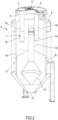
Figure 1 is a vertical raised view of a first embodiment of an apparatus made in accordance with the invention; -
Figure 2 is a vertical raised section view of an embodiment of a container (hopper) that is usable in the apparatus ofFigure 1 ; -
Figure 3 is a partial vertical raised section view of another embodiment of a container that is usable in the apparatus ofFigure 1 . - For the sake of simplicity, in the appended figures similar elements of different embodiments are indicated by the same numbering.
- With reference to the aforesaid figures, overall with 1 an apparatus has been indicated for processing incoherent plastics with a process fluid (for example heated air). The apparatus 1 comprises a
container 2 extending vertically with an internal volume configured to contain the incoherent plastics. Thecontainer 2 may comprise, in particular, a drying and/or dehumidifying hopper for drying and/or dehumidifying incoherent plastics (polymer granules). Thecontainer 2 may comprise, in particular, a vertical central longitudinal axis. - The apparatus 1 may comprise, in particular, an
outlet chamber 3 of the process fluid arranged above the internal volume containing the material. Theoutlet chamber 3 is provided with at least one outlet 4 of the process fluid. Theoutlet chamber 3 may be, in particular, separated from the internal volume, where the plastics are situated, by a diaphragm 5 (for example made of sheet metal) that is permeable to the process fluid. Thediaphragm 5 is provided with one ormore openings 6 to enable the process fluid to exit the internal volume. - The apparatus 1 comprises, for each of the
aforesaid openings 6, atubular body 7 extending below thediaphragm 5 and arranged inside the internal volume. Eachtubular body 7 is open above at the respective opening 6 in thediaphragm 5. Eachtubular body 7 may comprise, in particular, at least onesegment 7a that is permeable to the process fluid. Thissegment 7a that is permeable to the fluid may comprise, in particular, a tubular segment, for example a perforated tubular wall. Thissegment 7a that is permeable enables the process fluid to exit the internal volume through the respective opening. Thissegment 7a that is permeable may be, in particular, arranged in the internal volume so as to be completely immersed and surrounded (at 360° degrees) by the incoherent plastics that are processed once the internal volume has been sufficiently filled with the material. - The apparatus 1 comprises means for generating a flow of the process fluid inside the internal volume to the
outlet chamber 3. The means for generating a flow may comprise, in particular, at least one fan 8 to send the flow to an inlet 9 of thecontainer 2. The means for generating a flow may comprise, in particular, at least onefilter 10 for filtering the process fluid coming from the outlet 4 of the container. It is possible, as in the embodiment ofFigure 1 , for the apparatus 1 to comprise a closed circuit for the circulation of the process fluid. The fan 8 may operate in a closed circuit by removing the fluid from the outlet 4 and sending the fluid to the inlet 9. The apparatus 1 may comprise, in particular, regenerating means, for example of known type (not illustrated), to regenerate the fluid exiting thecontainer 2. The regenerated fluid may be sent in a closed circuit to the inlet 9 by the fan 8. - The
outlet chamber 3 may be, in particular, of annular shape. Theoutlet chamber 3 may be, in particular, internally bounded by atubular wall 11 that is permeable to the process fluid. Thetubular wall 11 may define, in particular, a passage for the entry of the incoherent plastics into the internal volume. - The apparatus 1 may comprise, in particular, a
loader 12 for feeding the incoherent plastics to the internal volume through thetubular wall 11. It is possible, as in the embodiments inFigures 2 and3 , for the material supplied by theloader 12 to pass inside thetubular wall 11 remaining isolated from the flow of the process fluid that exits through theoutlet chamber 3. - The apparatus 1 may comprise, in particular, a
discharge 13 for the processed material to exit. Thedischarge 13 may comprise, in particular, an outlet port arranged at the lower end of the internal volume. - The
diaphragm 5 may be, in particular, arranged radially around thetubular wall 11 starting from thetubular wall 11, so as to ensure substantial impermeability to the process fluid. Thediaphragm 5 may comprise, in particular, a wall of annular shape with an edge inside a closed loop (for example, of circular shape) directly connected (substantially coincident with) to a lower end edge of thetubular wall 11. - The aforesaid passage for the entry of the material and the
aforesaid outlet chamber 3 of the fluid may be, in particular, separated from one another by thetubular wall 11, so that theoutlet chamber 3 is substantially isolated, almost hermetically, from the course of the incoherent plastics, apart from the fluid communication represented by the permeable segment/s 7a. This fluid communication is anyway conformed and arranged so as to constitute an effective barrier to reduce or eliminate the undesired transit of incoherent material. - Each tubular body 7 (for example of cylindrical shape) may, in particular, extend along a longitudinal (for example, vertical) axis not coinciding with a longitudinal axis (for example, vertical) along which the tubular wall 11 (for example of cylindrical shape) extends. The longitudinal axis of each
tubular body 7 may be spaced apart from the longitudinal axis of thetubular wall 11. In particular, thetubular wall 11 may be arranged centrally with respect to a vertical central longitudinal axis of thecontainer 2, or with respect to a center of gravity of thediaphragm 5, whereas eachtubular body 7 may be arranged eccentrically with respect to the vertical central longitudinal axis of thecontainer 2, or with respect to the center of gravity of thediaphragm 5. - The apparatus 1 may comprise, in particular, an
inlet conduit 14 of the process fluid that is connected to the inlet 9 and is arranged in the internal volume and is permeable to the process fluid. Theinlet conduit 14 may, in particular, terminate below with a permeable portion 15 (for example, perforated) that is arranged to enable the process fluid to enter the internal volume. Thepermeable portion 15 may be, in particular, arranged below each of thetubular bodies 7, in particular below thesegments 7a that are permeable of thetubular bodies 7. Thepermeable portion 15 may comprise, in particular, a distributing cone. - The
permeable portion 15 may be, in particular, arranged in a manner that is central or coaxial with respect to the vertical central longitudinal axis of thecontainer 2. Eachtubular body 7 may be, in particular, arranged in a manner that is eccentric or offset with respect to thepermeable portion 15 and/or with respect to the vertical central longitudinal axis of thecontainer 2. This eccentric or offset arrangement, together with the fact that thesegment 7a that is permeable can be completely immersed and surrounded by the incoherent material, promotes the regularity and efficiency of the extraction of the process fluid from the internal volume of the container to the outlet 4. - The
diaphragm 5 may be, in particular, provided with two, or three, or four, or five, or more than fiveopenings 6, with each of which a respectivetubular body 7 is associated. Theopenings 6 may be arranged, in particular, spaced angularly apart from one another around a vertical axis of thecontainer 2. - As said, the
tubular body 7 may comprise asegment 7a (lower and/or tubular) that is permeable to the process fluid to enable the transit thereof from the outside inside thetubular body 7. Thetubular body 7 may comprise, in particular, an (upper or lower)segment 7b that is impermeable to the process fluid. Thesegment 7b that is impermeable may be arranged (for example coaxially) above thesegment 7a that is permeable. Thesegment 7a that is permeable (perforated) may be of cylindrical shape. Thesegment 7b that is impermeable (unperforated) may be of cylindrical shape. The (upper)segment 7b that is impermeable may extend, in particular, between the respective (lower)segment 7a that is permeable and therespective opening 6 on thediaphragm 5. A vertical length of the (upper)segment 7b that is impermeable may be, in particular, greater than a vertical length of the respective (lower)segment 7a that is permeable. - The apparatus 1 may comprise, in particular, at least one
perforated wall 16 which is permeable to the process fluid and arranged to bound laterally the internal volume and define an annular circulating zone of the process fluid. The apparatus 1 may comprise, in particular, at least oneexternal wall 17 that is permeable to the process fluid to bound laterally and externally the aforesaid annular zone. The apparatus 1 may comprise, in particular, one ormore septa 18 that are impermeable to the process fluid to divide the aforesaid annular zone into two or more compartments arranged one on top of the other. The aforesaid annular circulating zone of the process fluid promotes circulation with at least one component of the flow in a horizontal direction. The division into two or more compartments arranged one on top of the other promotes complex circulation in which the flow can enter and exit each compartment so as to be able to enter or exit each compartment so as to generate flow components in a horizontal direction radially outwards and several components of the flow in a horizontal direction radially inwards. - The operation of the apparatus may actuate, in particular, a method for processing incoherent plastics with a process fluid, in particular to dry and/or dehumidify incoherent plastics.
- The method may comprise, in particular, the step of generating a flow of a process fluid through incoherent plastics contained in an internal volume of a
container 2. The method may comprise, in particular, the step of extracting the process fluid from the internal volume through atubular body 7 which is at least partially permeable (for example perforated) to the fluid and provided above with anopening 6 that leads into anoutlet chamber 3 of the process fluid arranged above the internal volume and separated from the internal volume by adiaphragm 5 which is permeable to the process fluid. - The method may comprise, in particular, the step of extracting the process fluid through two or more tubular bodies 7 (each of which is at least partially permeable to the fluid) that are arranged angularly spaced apart from one another around a central vertical axis of the
container 2. The process fluid may then be extracted, in particular, through two or more removal zones (in particular, tubular removal zones), i.e. through N removal zones, with N = 2, 3, 4, 5, 6, 7, 8, 9, 10 or more. The number N of removal zones may be chosen in function of the maximum flowrate of the process fluid and/or of the diameter/height ratio of the container 2 (hopper). The embodiments ofFigs 2 and3 differ from one another substantially through the number of removal or extraction zones for removing or extracting the process fluid, i.e.tubular bodies 7. - Inserting one or more extracting or removing zones for extracting or removing the process fluid with an eccentric arrangement with respect to the central vertical axis of the
container 2, immersed inside the mass of the incoherent material, promotes the formation of a flow of the process fluid (hot air) so as to reduce the clogging of the filtering means with the incoherent material. It has been also seen that this arrangement that is eccentric and immersed in the material increases the efficiency of the process fluid, in particular for a flow that traverses the material in a complex manner with motion components in various horizontal directions and the motion component in a vertical direction.
Claims (15)
- Apparatus for processing incoherent plastics with a process fluid, said apparatus (1) comprising:- a container (2) extended vertically with an internal volume configured to contain the incoherent plastics;- a process fluid outlet chamber (3) arranged above said internal volume and separated from said internal volume by a diaphragm (5) impermeable to the process fluid and provided with one or more openings (6) for the outlet of the process fluid from said internal volume;- for each of said one or more openings (6), a tubular body (7) open at the top at the respective opening (6) and at least partially permeable to the process fluid so as to allow the process fluid to exit from said internal volume through the respective opening (6);- a tubular wall (11) which is impermeable to the process fluid, and which defines a passage for the inlet of the incoherent plastics in said internal volume, said outlet chamber (3) being internally delimited by said tubular wall (11);- means for generating a flow of the process fluid inside said internal volume towards said outlet chamber (3);characterized in that said tubular body (7) extends below said diaphragm (5) inside said internal volume.
- Apparatus according to claim 1, wherein said outlet chamber (3) is annular in shape, said passage and said outlet chamber (3) being separated from each other by said tubular wall (11).
- Apparatus according to claim 2, wherein said diaphragm (5) extends around said tubular wall (11).
- Apparatus according to claim 2 or 3, wherein said tubular body (7) extends along a longitudinal axis not coinciding with a longitudinal axis along which said tubular wall (11) extends.
- Apparatus according to any one of the preceding claims, comprising an inlet conduit (14) for the process fluid arranged in said internal volume and impermeable to the process fluid, said inlet conduit (14) terminating at the bottom with a permeable portion (15) arranged to allow the process fluid to enter said internal volume.
- Apparatus according to claim 5, wherein said permeable portion (15) is arranged below said tubular body (7).
- Apparatus according to any one of the preceding claims, wherein said diaphragm (5) is provided with two, or three, or four, or five, or more than five openings (6), each of which is associated with a respective tubular body (7); said openings (6) being arranged, in particular, angularly spaced from each other around a vertical axis of said container (2).
- Apparatus according to any one of the preceding claims, wherein said means for generating a flow comprises at least one fan (8) for sending the flow to an inlet (9) of said container (2) and/or at least one filter (10) to filter the process fluid coming from an outlet (4) of said container (2).
- Apparatus according to any one of the preceding claims, wherein said tubular body (7) comprises a segment (7a) that is permeable to the process fluid to allow its passage from the outside to the inside of the tubular body (7) and a segment (7b) that is impermeable to the process fluid.
- Apparatus according to claim 9, wherein said impermeable segment (7b) is arranged above the respective permeable segment (7a).
- Apparatus according to claim 10, wherein said impermeable segment (7b) is interposed between the respective permeable segment (7a) and the respective opening (6) on said diaphragm (5).
- Apparatus according to any one of the preceding claims, comprising at least one perforated wall (16) that is permeable to the process fluid and is arranged to laterally delimit said internal volume and to define an annular zone for the circulation of the process fluid, and at least one external wall (17) to delimit said annular zone laterally and externally.
- Apparatus according to claim 12, comprising one or more septa (18) impermeable to the process fluid to divide said annular zone into two or more compartments arranged one above the other.
- Apparatus according to any one of the preceding claims:- said container (2) comprising at least one inlet (9) of a process fluid and at least one outlet (4) of the process fluid;- said means for generating a flow of the process fluid from said at least one inlet (9) to said at least one outlet (4);- two or more tubular bodies (7) arranged in said internal volume and angularly spaced relative to each other around a vertical axis of said container (2), each of said two or more tubular bodies (7) being provided with an upper opening (6) connected to said outlet (4), each of said two or more tubular bodies (7) being at least partly permeable to the process fluid to allow the process fluid to exit through the respective openings (6).
- Method for processing incoherent plastics with a process fluid using the apparatus of claim 1, in particular for drying and/or dehumidifying incoherent plastics, said method comprising the step of generating a flow of a process fluid through incoherent plastics contained in an internal volume of a container (2), the step of introducing said incoherent plastics into said internal volume through a passage defined by a tubular wall (11) which is impermeable to the process fluid and which internally delimits an outlet chamber (3), and the step of extracting the process fluid from said internal volume through at least one tubular body (7) at least partially permeable to the process fluid and through an upper opening (6) of said tubular body (7 ) which flows into said outlet chamber (3) of the process fluid arranged above said internal volume, said outlet chamber (3) being separated from said internal volume by a diaphragm (5) that is impermeable to the process fluid.
Applications Claiming Priority (1)
| Application Number | Priority Date | Filing Date | Title |
|---|---|---|---|
| IT102022000011555A IT202200011555A1 (en) | 2022-05-31 | 2022-05-31 | Apparatus and method for processing material in a hopper |
Publications (2)
| Publication Number | Publication Date |
|---|---|
| EP4286128A1 EP4286128A1 (en) | 2023-12-06 |
| EP4286128B1 true EP4286128B1 (en) | 2024-10-09 |
Family
ID=82943322
Family Applications (1)
| Application Number | Title | Priority Date | Filing Date |
|---|---|---|---|
| EP23174837.7A Active EP4286128B1 (en) | 2022-05-31 | 2023-05-23 | Apparatus and method for processing material in a hopper |
Country Status (2)
| Country | Link |
|---|---|
| EP (1) | EP4286128B1 (en) |
| IT (1) | IT202200011555A1 (en) |
Family Cites Families (8)
| Publication number | Priority date | Publication date | Assignee | Title |
|---|---|---|---|---|
| DE4234696C2 (en) * | 1991-10-14 | 1994-06-09 | Werner Koch | Device for drying plastic bulk goods |
| DE102006024126A1 (en) * | 2006-05-22 | 2007-11-29 | Bühler AG | Device for drying crystallizable synthetic material, comprises a processing space for uptake of the synthetic material, feed- and discharge openings for the synthetic material, process gas feed mechanisms, and process gas exhaust systems |
| ITVR20070140A1 (en) * | 2007-10-09 | 2009-04-10 | Moretto Spa | GRANULAR MATERIAL TREATMENT UNIT EQUIPPED WITH HEAT RECOVERY GROUP |
| CN108973003A (en) * | 2018-08-07 | 2018-12-11 | 安徽龙锐模塑有限公司 | A kind of injection molding machine baking material bucket |
| EP3870418B1 (en) | 2018-10-24 | 2025-12-10 | Stefan Bock | Method and device for the fast and efficient heating of plastic granulates for preparing for the processing in a plasticization |
| CN110671909A (en) * | 2019-10-30 | 2020-01-10 | 太仓金昊达新材料有限公司 | Plastic pellet dries by fire material machine |
| CN111589792A (en) * | 2020-05-28 | 2020-08-28 | 合肥德捷节能环保科技有限公司 | Plastic master batch dedusting, cleaning and drying integrated device |
| CN114986737A (en) * | 2021-03-26 | 2022-09-02 | 浙江方欣新材料有限公司 | Nylon fiber, antibacterial nylon fiber and production method of flame-retardant nylon fiber |
-
2022
- 2022-05-31 IT IT102022000011555A patent/IT202200011555A1/en unknown
-
2023
- 2023-05-23 EP EP23174837.7A patent/EP4286128B1/en active Active
Also Published As
| Publication number | Publication date |
|---|---|
| EP4286128A1 (en) | 2023-12-06 |
| IT202200011555A1 (en) | 2023-12-01 |
Similar Documents
| Publication | Publication Date | Title |
|---|---|---|
| US4591324A (en) | Granulating apparatus | |
| US2561392A (en) | Process and apparatus for treating solutions to recover and coat solid particles | |
| US4584366A (en) | Process for the crystallizing, drying and aftercondensation of polycondensates | |
| EP2999933B1 (en) | Process for drying and powderizing functional foods, nutraceuticals, and natural health ingredients | |
| US20150246333A1 (en) | Agglomeration apparatus and method for producing agglomerated particles | |
| US8142551B2 (en) | Energy recuperating filtration apparatus | |
| FI82980B (en) | FOERFARANDE OCH ANORDNING FOER AVLAEGSNANDE AV VATTEN FRAON PARTIKELFORMIGT MATERIAL. | |
| DK151128B (en) | PROCEDURE AND APPARATUS FOR TREATMENT OF POWDER OR CORNED MATERIALS | |
| WO2009018996A2 (en) | Method and apparatus for drying a material | |
| KR20070087076A (en) | Rotary fluidized bed apparatus and method in a series of cylindrical chambers | |
| JPWO1997024570A1 (en) | Drying method and drying device for powder and granular material | |
| US11913721B2 (en) | Apparatus, a bottom plate component and a method for drying bulk particulate material | |
| EP4286128A1 (en) | Apparatus and method for processing material in a hopper | |
| FI78383B (en) | FOERFARANDE FOER BEHANDLING AV PARTIKELFORMIGT MATERIAL. | |
| EP3550242B1 (en) | An apparatus for drying bulk particulate material and a method of drying bulk particulate material | |
| EP4470742A1 (en) | Apparatus and method for processing incoherent material | |
| WO2008121020A1 (en) | Granulated product producing method and a drum granulator | |
| PL204355B1 (en) | Spray-drying device | |
| WO2017092758A1 (en) | Powder drying system with improved filter unit cleaning arrangement and method for cleaning the system | |
| US20240269896A1 (en) | System and method for recovering plastic recycling material | |
| WO2013020832A2 (en) | Capsule treatment | |
| US789109A (en) | Apparatus for treating materials. | |
| DK201570798A1 (en) | Powder drying system with improved filter unit cleaning arrangement and method for cleaning the system | |
| CN211329290U (en) | Granulation system | |
| GB2050182A (en) | Method of and apparatus for drying liquid suspensions or solution |
Legal Events
| Date | Code | Title | Description |
|---|---|---|---|
| PUAI | Public reference made under article 153(3) epc to a published international application that has entered the european phase |
Free format text: ORIGINAL CODE: 0009012 |
|
| STAA | Information on the status of an ep patent application or granted ep patent |
Free format text: STATUS: REQUEST FOR EXAMINATION WAS MADE |
|
| 17P | Request for examination filed |
Effective date: 20231031 |
|
| AK | Designated contracting states |
Kind code of ref document: A1 Designated state(s): AL AT BE BG CH CY CZ DE DK EE ES FI FR GB GR HR HU IE IS IT LI LT LU LV MC ME MK MT NL NO PL PT RO RS SE SI SK SM TR |
|
| GRAP | Despatch of communication of intention to grant a patent |
Free format text: ORIGINAL CODE: EPIDOSNIGR1 |
|
| STAA | Information on the status of an ep patent application or granted ep patent |
Free format text: STATUS: GRANT OF PATENT IS INTENDED |
|
| RIC1 | Information provided on ipc code assigned before grant |
Ipc: F26B 17/12 20060101ALI20240417BHEP Ipc: F26B 3/14 20060101ALI20240417BHEP Ipc: F26B 3/06 20060101ALI20240417BHEP Ipc: B29B 13/06 20060101ALI20240417BHEP Ipc: B29B 13/02 20060101AFI20240417BHEP |
|
| INTG | Intention to grant announced |
Effective date: 20240430 |
|
| P01 | Opt-out of the competence of the unified patent court (upc) registered |
Free format text: CASE NUMBER: APP_42075/2024 Effective date: 20240716 |
|
| GRAS | Grant fee paid |
Free format text: ORIGINAL CODE: EPIDOSNIGR3 |
|
| GRAA | (expected) grant |
Free format text: ORIGINAL CODE: 0009210 |
|
| STAA | Information on the status of an ep patent application or granted ep patent |
Free format text: STATUS: THE PATENT HAS BEEN GRANTED |
|
| AK | Designated contracting states |
Kind code of ref document: B1 Designated state(s): AL AT BE BG CH CY CZ DE DK EE ES FI FR GB GR HR HU IE IS IT LI LT LU LV MC ME MK MT NL NO PL PT RO RS SE SI SK SM TR |
|
| REG | Reference to a national code |
Ref country code: CH Ref legal event code: EP |
|
| REG | Reference to a national code |
Ref country code: DE Ref legal event code: R096 Ref document number: 602023000690 Country of ref document: DE |
|
| REG | Reference to a national code |
Ref country code: IE Ref legal event code: FG4D |
|
| REG | Reference to a national code |
Ref country code: LT Ref legal event code: MG9D |
|
| REG | Reference to a national code |
Ref country code: NL Ref legal event code: MP Effective date: 20241009 |
|
| PG25 | Lapsed in a contracting state [announced via postgrant information from national office to epo] |
Ref country code: NL Free format text: LAPSE BECAUSE OF FAILURE TO SUBMIT A TRANSLATION OF THE DESCRIPTION OR TO PAY THE FEE WITHIN THE PRESCRIBED TIME-LIMIT Effective date: 20241009 |
|
| PG25 | Lapsed in a contracting state [announced via postgrant information from national office to epo] |
Ref country code: NL Free format text: LAPSE BECAUSE OF FAILURE TO SUBMIT A TRANSLATION OF THE DESCRIPTION OR TO PAY THE FEE WITHIN THE PRESCRIBED TIME-LIMIT Effective date: 20241009 |
|
| PG25 | Lapsed in a contracting state [announced via postgrant information from national office to epo] |
Ref country code: HR Free format text: LAPSE BECAUSE OF FAILURE TO SUBMIT A TRANSLATION OF THE DESCRIPTION OR TO PAY THE FEE WITHIN THE PRESCRIBED TIME-LIMIT Effective date: 20241009 Ref country code: IS Free format text: LAPSE BECAUSE OF FAILURE TO SUBMIT A TRANSLATION OF THE DESCRIPTION OR TO PAY THE FEE WITHIN THE PRESCRIBED TIME-LIMIT Effective date: 20250209 Ref country code: PT Free format text: LAPSE BECAUSE OF FAILURE TO SUBMIT A TRANSLATION OF THE DESCRIPTION OR TO PAY THE FEE WITHIN THE PRESCRIBED TIME-LIMIT Effective date: 20250210 |
|
| PG25 | Lapsed in a contracting state [announced via postgrant information from national office to epo] |
Ref country code: FI Free format text: LAPSE BECAUSE OF FAILURE TO SUBMIT A TRANSLATION OF THE DESCRIPTION OR TO PAY THE FEE WITHIN THE PRESCRIBED TIME-LIMIT Effective date: 20241009 |
|
| PG25 | Lapsed in a contracting state [announced via postgrant information from national office to epo] |
Ref country code: BG Free format text: LAPSE BECAUSE OF FAILURE TO SUBMIT A TRANSLATION OF THE DESCRIPTION OR TO PAY THE FEE WITHIN THE PRESCRIBED TIME-LIMIT Effective date: 20241009 |
|
| PG25 | Lapsed in a contracting state [announced via postgrant information from national office to epo] |
Ref country code: ES Free format text: LAPSE BECAUSE OF FAILURE TO SUBMIT A TRANSLATION OF THE DESCRIPTION OR TO PAY THE FEE WITHIN THE PRESCRIBED TIME-LIMIT Effective date: 20241009 |
|
| PG25 | Lapsed in a contracting state [announced via postgrant information from national office to epo] |
Ref country code: NO Free format text: LAPSE BECAUSE OF FAILURE TO SUBMIT A TRANSLATION OF THE DESCRIPTION OR TO PAY THE FEE WITHIN THE PRESCRIBED TIME-LIMIT Effective date: 20250109 |
|
| PG25 | Lapsed in a contracting state [announced via postgrant information from national office to epo] |
Ref country code: LV Free format text: LAPSE BECAUSE OF FAILURE TO SUBMIT A TRANSLATION OF THE DESCRIPTION OR TO PAY THE FEE WITHIN THE PRESCRIBED TIME-LIMIT Effective date: 20241009 Ref country code: GR Free format text: LAPSE BECAUSE OF FAILURE TO SUBMIT A TRANSLATION OF THE DESCRIPTION OR TO PAY THE FEE WITHIN THE PRESCRIBED TIME-LIMIT Effective date: 20250110 |
|
| PG25 | Lapsed in a contracting state [announced via postgrant information from national office to epo] |
Ref country code: PL Free format text: LAPSE BECAUSE OF FAILURE TO SUBMIT A TRANSLATION OF THE DESCRIPTION OR TO PAY THE FEE WITHIN THE PRESCRIBED TIME-LIMIT Effective date: 20241009 |
|
| PG25 | Lapsed in a contracting state [announced via postgrant information from national office to epo] |
Ref country code: RS Free format text: LAPSE BECAUSE OF FAILURE TO SUBMIT A TRANSLATION OF THE DESCRIPTION OR TO PAY THE FEE WITHIN THE PRESCRIBED TIME-LIMIT Effective date: 20250109 |
|
| PG25 | Lapsed in a contracting state [announced via postgrant information from national office to epo] |
Ref country code: SM Free format text: LAPSE BECAUSE OF FAILURE TO SUBMIT A TRANSLATION OF THE DESCRIPTION OR TO PAY THE FEE WITHIN THE PRESCRIBED TIME-LIMIT Effective date: 20241009 |
|
| PGFP | Annual fee paid to national office [announced via postgrant information from national office to epo] |
Ref country code: DE Payment date: 20250529 Year of fee payment: 3 |
|
| PG25 | Lapsed in a contracting state [announced via postgrant information from national office to epo] |
Ref country code: DK Free format text: LAPSE BECAUSE OF FAILURE TO SUBMIT A TRANSLATION OF THE DESCRIPTION OR TO PAY THE FEE WITHIN THE PRESCRIBED TIME-LIMIT Effective date: 20241009 |
|
| REG | Reference to a national code |
Ref country code: DE Ref legal event code: R097 Ref document number: 602023000690 Country of ref document: DE |
|
| PGFP | Annual fee paid to national office [announced via postgrant information from national office to epo] |
Ref country code: IT Payment date: 20250531 Year of fee payment: 3 |
|
| PG25 | Lapsed in a contracting state [announced via postgrant information from national office to epo] |
Ref country code: EE Free format text: LAPSE BECAUSE OF FAILURE TO SUBMIT A TRANSLATION OF THE DESCRIPTION OR TO PAY THE FEE WITHIN THE PRESCRIBED TIME-LIMIT Effective date: 20241009 |
|
| PG25 | Lapsed in a contracting state [announced via postgrant information from national office to epo] |
Ref country code: RO Free format text: LAPSE BECAUSE OF FAILURE TO SUBMIT A TRANSLATION OF THE DESCRIPTION OR TO PAY THE FEE WITHIN THE PRESCRIBED TIME-LIMIT Effective date: 20241009 |
|
| PGFP | Annual fee paid to national office [announced via postgrant information from national office to epo] |
Ref country code: AT Payment date: 20250721 Year of fee payment: 3 |
|
| PG25 | Lapsed in a contracting state [announced via postgrant information from national office to epo] |
Ref country code: SK Free format text: LAPSE BECAUSE OF FAILURE TO SUBMIT A TRANSLATION OF THE DESCRIPTION OR TO PAY THE FEE WITHIN THE PRESCRIBED TIME-LIMIT Effective date: 20241009 |
|
| PG25 | Lapsed in a contracting state [announced via postgrant information from national office to epo] |
Ref country code: CZ Free format text: LAPSE BECAUSE OF FAILURE TO SUBMIT A TRANSLATION OF THE DESCRIPTION OR TO PAY THE FEE WITHIN THE PRESCRIBED TIME-LIMIT Effective date: 20241009 |
|
| PLBE | No opposition filed within time limit |
Free format text: ORIGINAL CODE: 0009261 |
|
| STAA | Information on the status of an ep patent application or granted ep patent |
Free format text: STATUS: NO OPPOSITION FILED WITHIN TIME LIMIT |
|
| PG25 | Lapsed in a contracting state [announced via postgrant information from national office to epo] |
Ref country code: SE Free format text: LAPSE BECAUSE OF FAILURE TO SUBMIT A TRANSLATION OF THE DESCRIPTION OR TO PAY THE FEE WITHIN THE PRESCRIBED TIME-LIMIT Effective date: 20241009 |
|
| 26N | No opposition filed |
Effective date: 20250710 |
|
| PG25 | Lapsed in a contracting state [announced via postgrant information from national office to epo] |
Ref country code: LU Free format text: LAPSE BECAUSE OF NON-PAYMENT OF DUE FEES Effective date: 20250523 |
|
| REG | Reference to a national code |
Ref country code: BE Ref legal event code: MM Effective date: 20250531 |
|
| PG25 | Lapsed in a contracting state [announced via postgrant information from national office to epo] |
Ref country code: MC Free format text: LAPSE BECAUSE OF FAILURE TO SUBMIT A TRANSLATION OF THE DESCRIPTION OR TO PAY THE FEE WITHIN THE PRESCRIBED TIME-LIMIT Effective date: 20241009 |
|
| REG | Reference to a national code |
Ref country code: AT Ref legal event code: UEP Ref document number: 1730100 Country of ref document: AT Kind code of ref document: T Effective date: 20241009 |
|
| PG25 | Lapsed in a contracting state [announced via postgrant information from national office to epo] |
Ref country code: IE Free format text: LAPSE BECAUSE OF NON-PAYMENT OF DUE FEES Effective date: 20250523 |
|
| PG25 | Lapsed in a contracting state [announced via postgrant information from national office to epo] |
Ref country code: BE Free format text: LAPSE BECAUSE OF NON-PAYMENT OF DUE FEES Effective date: 20250531 |
|
| PG25 | Lapsed in a contracting state [announced via postgrant information from national office to epo] |
Ref country code: FR Free format text: LAPSE BECAUSE OF NON-PAYMENT OF DUE FEES Effective date: 20250531 |