EP4286127A1 - A fibrous preform comprising a plurality of hourglass-shaped voids - Google Patents
A fibrous preform comprising a plurality of hourglass-shaped voids Download PDFInfo
- Publication number
- EP4286127A1 EP4286127A1 EP23177242.7A EP23177242A EP4286127A1 EP 4286127 A1 EP4286127 A1 EP 4286127A1 EP 23177242 A EP23177242 A EP 23177242A EP 4286127 A1 EP4286127 A1 EP 4286127A1
- Authority
- EP
- European Patent Office
- Prior art keywords
- preform
- hourglass
- spikes
- spiked
- array
- Prior art date
- Legal status (The legal status is an assumption and is not a legal conclusion. Google has not performed a legal analysis and makes no representation as to the accuracy of the status listed.)
- Granted
Links
Images



Classifications
-
- B—PERFORMING OPERATIONS; TRANSPORTING
- B29—WORKING OF PLASTICS; WORKING OF SUBSTANCES IN A PLASTIC STATE IN GENERAL
- B29B—PREPARATION OR PRETREATMENT OF THE MATERIAL TO BE SHAPED; MAKING GRANULES OR PREFORMS; RECOVERY OF PLASTICS OR OTHER CONSTITUENTS OF WASTE MATERIAL CONTAINING PLASTICS
- B29B11/00—Making preforms
- B29B11/14—Making preforms characterised by structure or composition
- B29B11/16—Making preforms characterised by structure or composition comprising fillers or reinforcement
-
- C—CHEMISTRY; METALLURGY
- C04—CEMENTS; CONCRETE; ARTIFICIAL STONE; CERAMICS; REFRACTORIES
- C04B—LIME, MAGNESIA; SLAG; CEMENTS; COMPOSITIONS THEREOF, e.g. MORTARS, CONCRETE OR LIKE BUILDING MATERIALS; ARTIFICIAL STONE; CERAMICS; REFRACTORIES; TREATMENT OF NATURAL STONE
- C04B35/00—Shaped ceramic products characterised by their composition; Ceramics compositions; Processing powders of inorganic compounds preparatory to the manufacturing of ceramic products
- C04B35/71—Ceramic products containing macroscopic reinforcing agents
- C04B35/78—Ceramic products containing macroscopic reinforcing agents containing non-metallic materials
- C04B35/80—Fibres, filaments, whiskers, platelets, or the like
-
- B—PERFORMING OPERATIONS; TRANSPORTING
- B26—HAND CUTTING TOOLS; CUTTING; SEVERING
- B26F—PERFORATING; PUNCHING; CUTTING-OUT; STAMPING-OUT; SEVERING BY MEANS OTHER THAN CUTTING
- B26F1/00—Perforating; Punching; Cutting-out; Stamping-out; Apparatus therefor
- B26F1/24—Perforating by needles or pins
-
- B—PERFORMING OPERATIONS; TRANSPORTING
- B29—WORKING OF PLASTICS; WORKING OF SUBSTANCES IN A PLASTIC STATE IN GENERAL
- B29B—PREPARATION OR PRETREATMENT OF THE MATERIAL TO BE SHAPED; MAKING GRANULES OR PREFORMS; RECOVERY OF PLASTICS OR OTHER CONSTITUENTS OF WASTE MATERIAL CONTAINING PLASTICS
- B29B11/00—Making preforms
-
- C—CHEMISTRY; METALLURGY
- C04—CEMENTS; CONCRETE; ARTIFICIAL STONE; CERAMICS; REFRACTORIES
- C04B—LIME, MAGNESIA; SLAG; CEMENTS; COMPOSITIONS THEREOF, e.g. MORTARS, CONCRETE OR LIKE BUILDING MATERIALS; ARTIFICIAL STONE; CERAMICS; REFRACTORIES; TREATMENT OF NATURAL STONE
- C04B35/00—Shaped ceramic products characterised by their composition; Ceramics compositions; Processing powders of inorganic compounds preparatory to the manufacturing of ceramic products
- C04B35/515—Shaped ceramic products characterised by their composition; Ceramics compositions; Processing powders of inorganic compounds preparatory to the manufacturing of ceramic products based on non-oxide ceramics
- C04B35/56—Shaped ceramic products characterised by their composition; Ceramics compositions; Processing powders of inorganic compounds preparatory to the manufacturing of ceramic products based on non-oxide ceramics based on carbides or oxycarbides
- C04B35/565—Shaped ceramic products characterised by their composition; Ceramics compositions; Processing powders of inorganic compounds preparatory to the manufacturing of ceramic products based on non-oxide ceramics based on carbides or oxycarbides based on silicon carbide
-
- C—CHEMISTRY; METALLURGY
- C04—CEMENTS; CONCRETE; ARTIFICIAL STONE; CERAMICS; REFRACTORIES
- C04B—LIME, MAGNESIA; SLAG; CEMENTS; COMPOSITIONS THEREOF, e.g. MORTARS, CONCRETE OR LIKE BUILDING MATERIALS; ARTIFICIAL STONE; CERAMICS; REFRACTORIES; TREATMENT OF NATURAL STONE
- C04B35/00—Shaped ceramic products characterised by their composition; Ceramics compositions; Processing powders of inorganic compounds preparatory to the manufacturing of ceramic products
- C04B35/622—Forming processes; Processing powders of inorganic compounds preparatory to the manufacturing of ceramic products
-
- C—CHEMISTRY; METALLURGY
- C04—CEMENTS; CONCRETE; ARTIFICIAL STONE; CERAMICS; REFRACTORIES
- C04B—LIME, MAGNESIA; SLAG; CEMENTS; COMPOSITIONS THEREOF, e.g. MORTARS, CONCRETE OR LIKE BUILDING MATERIALS; ARTIFICIAL STONE; CERAMICS; REFRACTORIES; TREATMENT OF NATURAL STONE
- C04B35/00—Shaped ceramic products characterised by their composition; Ceramics compositions; Processing powders of inorganic compounds preparatory to the manufacturing of ceramic products
- C04B35/622—Forming processes; Processing powders of inorganic compounds preparatory to the manufacturing of ceramic products
- C04B35/626—Preparing or treating the powders individually or as batches ; preparing or treating macroscopic reinforcing agents for ceramic products, e.g. fibres; mechanical aspects section B
- C04B35/628—Coating the powders or the macroscopic reinforcing agents
- C04B35/62884—Coating the powders or the macroscopic reinforcing agents by gas phase techniques
-
- C—CHEMISTRY; METALLURGY
- C04—CEMENTS; CONCRETE; ARTIFICIAL STONE; CERAMICS; REFRACTORIES
- C04B—LIME, MAGNESIA; SLAG; CEMENTS; COMPOSITIONS THEREOF, e.g. MORTARS, CONCRETE OR LIKE BUILDING MATERIALS; ARTIFICIAL STONE; CERAMICS; REFRACTORIES; TREATMENT OF NATURAL STONE
- C04B35/00—Shaped ceramic products characterised by their composition; Ceramics compositions; Processing powders of inorganic compounds preparatory to the manufacturing of ceramic products
- C04B35/622—Forming processes; Processing powders of inorganic compounds preparatory to the manufacturing of ceramic products
- C04B35/626—Preparing or treating the powders individually or as batches ; preparing or treating macroscopic reinforcing agents for ceramic products, e.g. fibres; mechanical aspects section B
- C04B35/628—Coating the powders or the macroscopic reinforcing agents
- C04B35/62886—Coating the powders or the macroscopic reinforcing agents by wet chemical techniques
-
- C—CHEMISTRY; METALLURGY
- C04—CEMENTS; CONCRETE; ARTIFICIAL STONE; CERAMICS; REFRACTORIES
- C04B—LIME, MAGNESIA; SLAG; CEMENTS; COMPOSITIONS THEREOF, e.g. MORTARS, CONCRETE OR LIKE BUILDING MATERIALS; ARTIFICIAL STONE; CERAMICS; REFRACTORIES; TREATMENT OF NATURAL STONE
- C04B41/00—After-treatment of mortars, concrete, artificial stone or ceramics; Treatment of natural stone
- C04B41/009—After-treatment of mortars, concrete, artificial stone or ceramics; Treatment of natural stone characterised by the material treated
-
- C—CHEMISTRY; METALLURGY
- C04—CEMENTS; CONCRETE; ARTIFICIAL STONE; CERAMICS; REFRACTORIES
- C04B—LIME, MAGNESIA; SLAG; CEMENTS; COMPOSITIONS THEREOF, e.g. MORTARS, CONCRETE OR LIKE BUILDING MATERIALS; ARTIFICIAL STONE; CERAMICS; REFRACTORIES; TREATMENT OF NATURAL STONE
- C04B41/00—After-treatment of mortars, concrete, artificial stone or ceramics; Treatment of natural stone
- C04B41/80—After-treatment of mortars, concrete, artificial stone or ceramics; Treatment of natural stone of only ceramics
- C04B41/81—Coating or impregnation
- C04B41/89—Coating or impregnation for obtaining at least two superposed coatings having different compositions
-
- C—CHEMISTRY; METALLURGY
- C04—CEMENTS; CONCRETE; ARTIFICIAL STONE; CERAMICS; REFRACTORIES
- C04B—LIME, MAGNESIA; SLAG; CEMENTS; COMPOSITIONS THEREOF, e.g. MORTARS, CONCRETE OR LIKE BUILDING MATERIALS; ARTIFICIAL STONE; CERAMICS; REFRACTORIES; TREATMENT OF NATURAL STONE
- C04B2235/00—Aspects relating to ceramic starting mixtures or sintered ceramic products
- C04B2235/02—Composition of constituents of the starting material or of secondary phases of the final product
- C04B2235/30—Constituents and secondary phases not being of a fibrous nature
- C04B2235/38—Non-oxide ceramic constituents or additives
- C04B2235/3817—Carbides
- C04B2235/3826—Silicon carbides
-
- C—CHEMISTRY; METALLURGY
- C04—CEMENTS; CONCRETE; ARTIFICIAL STONE; CERAMICS; REFRACTORIES
- C04B—LIME, MAGNESIA; SLAG; CEMENTS; COMPOSITIONS THEREOF, e.g. MORTARS, CONCRETE OR LIKE BUILDING MATERIALS; ARTIFICIAL STONE; CERAMICS; REFRACTORIES; TREATMENT OF NATURAL STONE
- C04B2235/00—Aspects relating to ceramic starting mixtures or sintered ceramic products
- C04B2235/02—Composition of constituents of the starting material or of secondary phases of the final product
- C04B2235/50—Constituents or additives of the starting mixture chosen for their shape or used because of their shape or their physical appearance
- C04B2235/52—Constituents or additives characterised by their shapes
- C04B2235/5208—Fibers
- C04B2235/5216—Inorganic
- C04B2235/524—Non-oxidic, e.g. borides, carbides, silicides or nitrides
- C04B2235/5244—Silicon carbide
-
- C—CHEMISTRY; METALLURGY
- C04—CEMENTS; CONCRETE; ARTIFICIAL STONE; CERAMICS; REFRACTORIES
- C04B—LIME, MAGNESIA; SLAG; CEMENTS; COMPOSITIONS THEREOF, e.g. MORTARS, CONCRETE OR LIKE BUILDING MATERIALS; ARTIFICIAL STONE; CERAMICS; REFRACTORIES; TREATMENT OF NATURAL STONE
- C04B2235/00—Aspects relating to ceramic starting mixtures or sintered ceramic products
- C04B2235/02—Composition of constituents of the starting material or of secondary phases of the final product
- C04B2235/50—Constituents or additives of the starting mixture chosen for their shape or used because of their shape or their physical appearance
- C04B2235/52—Constituents or additives characterised by their shapes
- C04B2235/5208—Fibers
- C04B2235/5252—Fibers having a specific pre-form
- C04B2235/5256—Two-dimensional, e.g. woven structures
-
- C—CHEMISTRY; METALLURGY
- C04—CEMENTS; CONCRETE; ARTIFICIAL STONE; CERAMICS; REFRACTORIES
- C04B—LIME, MAGNESIA; SLAG; CEMENTS; COMPOSITIONS THEREOF, e.g. MORTARS, CONCRETE OR LIKE BUILDING MATERIALS; ARTIFICIAL STONE; CERAMICS; REFRACTORIES; TREATMENT OF NATURAL STONE
- C04B2235/00—Aspects relating to ceramic starting mixtures or sintered ceramic products
- C04B2235/60—Aspects relating to the preparation, properties or mechanical treatment of green bodies or pre-forms
-
- C—CHEMISTRY; METALLURGY
- C04—CEMENTS; CONCRETE; ARTIFICIAL STONE; CERAMICS; REFRACTORIES
- C04B—LIME, MAGNESIA; SLAG; CEMENTS; COMPOSITIONS THEREOF, e.g. MORTARS, CONCRETE OR LIKE BUILDING MATERIALS; ARTIFICIAL STONE; CERAMICS; REFRACTORIES; TREATMENT OF NATURAL STONE
- C04B2235/00—Aspects relating to ceramic starting mixtures or sintered ceramic products
- C04B2235/60—Aspects relating to the preparation, properties or mechanical treatment of green bodies or pre-forms
- C04B2235/614—Gas infiltration of green bodies or pre-forms
Definitions
- the present invention relates to ceramic matrix composites, and more particularly to the preparation of woven ceramic fabrics for use in ceramic matrix composites.
- a method of preparing a fibrous preform for use in a ceramic matrix composite comprises arranging the preform from a woven ceramic material, the preform comprising a pair of opposing outer surfaces and a midplane disposed between the pair of opposing outer surfaces, and perforating the preform with a spiked array to form a perforated preform.
- the perforated preform comprises a plurality of hourglass-shaped voids extending through a thickness of the preform.
- a fibrous preform that comprises an arrangement of woven ceramic material, a pair of oppositely disposed outer surfaces defining a thickness therebetween, a midplane disposed between the pair of oppositely disposed surfaces, and a plurality of hourglass-shaped voids extending through the thickness.
- This disclosure presents a method of and means for perforating a fibrous ceramic preform prior to densification via chemical vapor infiltration (CVI).
- CVI chemical vapor infiltration
- Multiple embodiments of spiked arrays can be used to create hourglass-shaped voids through the thickness of the preform. Such voids facilitate access to the preform midplane by reactant vapors such that matrix deposits in a more even, inside-out manner.
- the combined inter-tow and intra-tow porosities can represent a total porosity of preform 10 (and the resulting CMC) as a whole.
- a midplane point, represented by line M, lies generally midway between opposing outer surfaces 12.
- Outer surfaces 12 also delimit a through-thickness T of the illustrated portion of preform 10.
- FIGS. 2A and 2B illustrate alternative embodiments of spikes array 20 of FIG. 1 . More specifically, FIG. 2A is a simplified illustration of a subset of linear, conical spikes 22A of spiked array 20A shown in isolation. FIG. 2B is a simplified illustration of an alternative subset of spikes 22B with a non-linear, concave profile. FIGS. 2A and 2B are discussed together.
- Spikes 22A extend from backplate 24A and have a conical geometry with a linear taper.
- Spikes 22B extend from backplate 24B and are non-linear with a combination of concave curvature and straight segments. Other combinations of curved and/or straight segments are possible, for example, with a further alternative embodiment including convexly curved (i.e., outwardly bowed) sides.
- lengths L1, L2 of spikes 22A, 22B is generally uniform across a given spiked array 20A, 20B, although in an alternative embodiment, the length of one or a subset of spikes 22A, 22B can be greater than other spikes in a given array 20A, 20B. For example, longer spikes 22A, 22B may be necessary where curvature in preform 10 exists, as the outer surface 12 at such location can be further from (i.e., not flush with) plate 16.
- Each spike 22A can be tapered such that base 26A has a base diameter d 1 that is wider than a tip diameter d 2 .
- each spike 22B can be tapered, although non-linearly, having a base diameter d 3 and a tip diameter d 4 .
- d 1 and/or d 3 can range from 1.0 x 10 -1 mm to 1.0 mm, and can further be between 1.1 and 10 times greater than d 2 and/or d 4 .
- the distance Ds between adjacent spikes 22A and/or 22B can be taken from the center/midpoint of each base 26A, 26B. In either embodiment, distance D S can range from 1.6 x 10 -1 mm (0.16 mm) to 7.62 mm.
- spikes 22A and/or 22B can be formed from a printed polymer material, and any polymer contaminants in preform 20 from the perforation process would burn off during densification.
- spikes 22A and/or 22B can be formed from a ceramic-coated (e.g., SiC) metallic material, with any contaminants being from the ceramic coating and beneficially incorporated into the densified component.
- FIG. 3 is a simplified cross-sectional view of the portion of preform 10 from FIG. 1 after being perforated from both sides (i.e., through both outer surfaces 12) by spiked array 20A. Accordingly, FIG. 3 illustrates a perforated preform 10. As shown in FIG. 3 , hourglass-shaped voids 30A which correspond generally to a geometry of spikes 22A having straight sides/edges. Voids 30A extend through thickness T of preform 10, and represent locations where spikes 22A were pushed into preform 10 from each outer surface 12 in such manner as to have opposing tips 28A more or less aligned.
- Dashed lines forming concave hourglass shapes represent an alternative geometry of void 30B which can be similarly formed by, for example, spikes 22B such that voids 30B have concave/curved sides. Accordingly, the geometry of each void 30A, 30B from the midplane to one outer surface 12 or the other corresponds to the three-dimensional geometry (i.e., shape, length, diameters, etc.) of an individual spike 22A, 22B, respectively, and further to the arrangement and spacing of the respective spiked array 20A, 20B.
- spacing between adjacent voids 30A and/or 30B, or distance D V , measured from the center of one void 30A and/or 30B at outer surface 12 to the center of the adjacent void 30A and/or 30B can be equal to the distance D S between respective adjacent spikes 22A and/or 22B.
- the widest points (at outer surfaces 12) of each void 30A and/or 30B will correspond in size and shape to base diameter d 1 and/or d 3 , while the narrowest point (at the midplane) will correspond to tip diameter d 2 and/or d 4 .
- Voids 30A and/or 30B further align with holes 18 within tooling 14.
- preform 10 can include voids with convexly curved sides if such spikes are included in the spiked array.
- FIG. 4 is a simplified illustration of an alternative spiked array 120, shown as a two-sided pressing apparatus.
- Spiked array 120 includes upper backplate 124 U and lower backplate 124 L with respective upper and lower spikes 122 U and 122 L (collectively referred to as "spikes 122").
- Spikes 122 U and 122 L can be substantially similar to spikes 22 discussed above.
- Backplate 124 U and 124 L are connected to hinge 129, and one or both backplates may be movable about hinge 129.
- one backplate e.g., lower backplate 124 L
- the other backplate e.g., upper backplate 124 U
- Spiked array 120 can be used to perforate generally planar segments of preform 10, and need not be guided by holes 18 of tooling 14. This is due to the fact that upper spikes 122 U are aligned with corresponding lower spikes 122 L . Spiked array 120 may be preferable for quickly perforating relatively large areas (e.g., ⁇ 1.0 ft 2 ( ⁇ 0.09 m 2 )) of woven fabric. Additionally, since spiked array 120 can be used without tooling 14, the layout of upper and/or lower spikes 122 U and 122 L is not constrained by a requirement to match holes 18, and can be arranged in various array patterns, such as square, staggered, etc. Although shown with more conical spikes 122, spiked array 120 can additionally and/or alternatively includes spikes similar to those shown in FIG. 2B .
- FIG. 5 is a method flowchart illustrating select steps of method 200 for preparing a perforated preform, such as preform 10 of FIG. 3 , for use in a CMC.
- FIG. 6 is a simplified cross-sectional view of a section of CMC 332 formed using method 200. Method 200 is discussed together with FIGS. 1-4 and 6 .
- a net shape or near-net shape preform (e.g., preform 10) can be arranged.
- a preform can include various layers of woven fiber plies, braids, etc., and can further include a polymer-based binder or tackifier such that the underlying ceramic fabric is wet and somewhat pliable.
- the preform can be perforated with a spiked array to form a perforated preform.
- preform 10 must first be mounted on graphite tooling 14.
- Spikes 22 can be aligned with holes 18 and inserted into preform 10 to the midplane. If using only a single spiked array 20, spikes 22 can be removed and aligned with holes 18 on the other (unperforated) side of preform 10 and inserted to reach the midplane such that the hourglass voids of FIG. 3 are formed. If using multiple spiked arrays 20, spikes 22 can be inserted more or less simultaneously in an aligned manner.
- step 204 can include placing a portion of the preform into the apparatus and bringing upper and lower backplates 124 U and 124 L together such that corresponding spikes 122 U and 122 L meet or nearly meet at the midplane.
- the perforated preform 10 can then be subsequently placed in requisite tooling in preparation for step 206.
- preform can undergo matrix formation and densification within a reaction chamber using CVI.
- voids 30A and/or 30B in perforated preform 10 align with holes 18 in graphite tooling 14, which gives the reactant vapors access to voids 30A and/or 30B.
- the matrix material can be SiC or other suitable ceramic material. Densification is carried out until the resulting CMC has reached the desired residual porosity. If not previously burned off/decomposed, for example, during debulking, any polymer or ceramic contaminants from spikes 22, 122 remaining in preform 10 will burn off and/or decompose during step 206.
- the matrix can deposit in an inside-out manner, referring directionally from the midplane to an outer surface 12.
- the widening in the outward direction due to the larger base diameter d 1 and/or d 3 prevents "canning off of the preform region near the midplane, where the matrix deposits too quickly near the outer surface of the preform and prevents vapors from accessing the midplane region. This can lead to asymmetrical densification with an undesirably porous midplane region compared to sufficiently densified outer surfaces.
- CMC 332 is shown in FIG. 6 with matrix 334 deposited where voids 30A and/or 30B of preform 10 had been.
- matrix 334 deposits in and around fibers of preform 10 in a generally uniform manner.
- the final inter-tow porosity can range from 10% to 15% with a total porosity of over 20%.
- the disclosed perforated preforms can be used to form CMCs (e.g., CMC 332) with a final inter-tow porosity of less than 10% such that the total porosity of the CMC is less than 20%.
- a method of preparing a fibrous preform for use in a ceramic matrix composite comprises arranging the preform from a woven ceramic material, the preform comprising a pair of opposing outer surfaces and a midplane disposed between the pair of opposing outer surfaces, and perforating the preform with a spiked array to form a perforated preform.
- the perforated preform comprises a plurality of hourglass-shaped voids extending through a thickness of the preform.
- the method of the preceding paragraph can optionally include, additionally and/or alternatively, any one or more of the following features, configurations and/or additional components:
- the above method can further include, prior to perforating the preform, laying-up the preform on tooling, the tooling comprising a first plate along one outer surface of the pair of opposing outer surfaces, and a plurality of holes through the plate.
- the spiked array can be a two-sided pressing apparatus, and perforating the preform can further include placing the preform between a plurality of upper and lower spikes of the spiked array, and pressing the upper and lower spikes into the preform.
- arranging the preform can further include applying a polymer material to the preform to wet the preform.
- Any of the above methods can further include applying at least one of a thermal barrier coating and an environmental barrier coating to the ceramic matrix composite.
- a ceramic matrix composite can include any of the above preforms, and a ceramic matrix deposited on and around the woven ceramic material and filling the plurality of hourglass-shaped voids.
- the ceramic matrix can include silicon carbide.
- any of the above ceramic matrix composites can further include at least one of a thermal barrier coating and an environmental barrier coating.
Landscapes
- Chemical & Material Sciences (AREA)
- Engineering & Computer Science (AREA)
- Ceramic Engineering (AREA)
- Manufacturing & Machinery (AREA)
- Structural Engineering (AREA)
- Organic Chemistry (AREA)
- Materials Engineering (AREA)
- Chemical Kinetics & Catalysis (AREA)
- Inorganic Chemistry (AREA)
- Mechanical Engineering (AREA)
- General Chemical & Material Sciences (AREA)
- Life Sciences & Earth Sciences (AREA)
- Forests & Forestry (AREA)
- Ceramic Products (AREA)
Abstract
Description
- The present invention relates to ceramic matrix composites, and more particularly to the preparation of woven ceramic fabrics for use in ceramic matrix composites.
- In the processing of ceramic matrix composites, there is a need to infiltrate matrix within and around fibrous tow bundles to replace pore volume with dense matrix material. In a woven system, large voids often exist between adj acent tows of a preform-such voids can become large defects after infiltration of the composite that are detrimental to composite properties. The pore network through a woven system is often highly tortuous for infiltrating reactant vapors, which leads to uneven deposition through the thickness of the preform. Instead, higher concentrations tend to deposit on preform surfaces and edges. This leads to an overall slower and less uniform matrix infiltration process resulting in composites with undesirably porous midplanes. Thus, a need exists for means to facilitate even matrix infiltration.
- From one aspect, there is provided a method of preparing a fibrous preform for use in a ceramic matrix composite that comprises arranging the preform from a woven ceramic material, the preform comprising a pair of opposing outer surfaces and a midplane disposed between the pair of opposing outer surfaces, and perforating the preform with a spiked array to form a perforated preform. The perforated preform comprises a plurality of hourglass-shaped voids extending through a thickness of the preform.
- There is also provided a fibrous preform that comprises an arrangement of woven ceramic material, a pair of oppositely disposed outer surfaces defining a thickness therebetween, a midplane disposed between the pair of oppositely disposed surfaces, and a plurality of hourglass-shaped voids extending through the thickness.
-
-
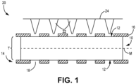
FIG. 1 is a simplified cross-sectional view of a fibrous preform prior to perforation by a first embodiment of a spiked array. -
FIGS. 2A and 2B are simplified illustrations of subsets of alternatively shaped spikes from the spiked array ofFIG. 1 . -
FIG. 3 is a simplified cross-sectional view of a perforated fibrous preform showing voids formed by the spiked array ofFIG. 1 . -
FIG. 4 is a simplified illustration of an alternative spiked array for use in perforating a fibrous preform. -
FIG. 5 is a method flow chart illustrating steps of a method of preparing a perforated preform for use in a ceramic matrix composite (CMC). -
FIG. 6 is a simplified cross-sectional view of a CMC formed using the method ofFIG. 5 . - While the above-identified figures set forth one or more embodiments of the present disclosure, other embodiments are also contemplated, as noted in the discussion. In all cases, this disclosure presents the invention by way of representation and not limitation. It should be understood that numerous other modifications and embodiments can be devised by those skilled in the art, which fall within the scope and spirit of the principles of the invention. The figures may not be drawn to scale, and applications and embodiments of the present invention may include features and components not specifically shown in the drawings.
- This disclosure presents a method of and means for perforating a fibrous ceramic preform prior to densification via chemical vapor infiltration (CVI). Multiple embodiments of spiked arrays can be used to create hourglass-shaped voids through the thickness of the preform. Such voids facilitate access to the preform midplane by reactant vapors such that matrix deposits in a more even, inside-out manner.
-
FIG. 1 is simplified cross-sectional view of a portion offibrous preform 10 prior to perforation withspiked array 20. Preform 10 can be formed from bundled ceramic (e.g., silicon carbide - SiC) tows, arranged in one of various woven architectures such as plain, harness (e.g., 3, 5, 8, etc.), twill, braid, or non-symmetric to name a few non-limiting examples. Preform 10 can have a bimodal pore distribution including intra-tow pores (i.e., open spaces between filaments within a tow) and inter-tow pores (i.e., open spaces between adjacent tows). The combined inter-tow and intra-tow porosities can represent a total porosity of preform 10 (and the resulting CMC) as a whole. A midplane point, represented by line M, lies generally midway between opposingouter surfaces 12.Outer surfaces 12 also delimit a through-thickness T of the illustrated portion ofpreform 10. - As shown in
FIG. 1 ,preform 10 is situated withintooling 14, which can includeopposing plates 16, one in contact with each preformouter surface 12.Plates 16 can be formed, for example, of graphite. Eachplate 16 can includeholes 18 which facilitate the passage of reactant vapors intopreform 10 during the CVI process, as is discussed in greater detail below.Holes 18 can also serve as a guide forspiked array 20.Spiked array 20 can includemultiple spikes 22 arranged in rows and columns onbackplate 24 in alignment withholes 18 ofplate 16. Eachspike 22 can have a generally tapered three-dimensional shape with a base (labeled inFIGS. 2A and 2B as 26A and 26B, respectively), an oppositely disposed tip (labeled inFIGS. 2A and 2B as 28A and 28B, respectively), and a length (labeled inFIGS. 2A and 2B as L1 and L2, respectively) extending therebetween. Generally, the length ofspikes 22 will be suitable to reach the midplane once pushed into preform 10 through oneouter surface 12 or the other, as is discussed in greater detail below. The tips can be slightly to moderately blunted or rounded to reduce damage to the tows during insertion ofspikes 22 intopreform 10. -
FIGS. 2A and 2B illustrate alternative embodiments ofspikes array 20 ofFIG. 1 . More specifically,FIG. 2A is a simplified illustration of a subset of linear,conical spikes 22A ofspiked array 20A shown in isolation.FIG. 2B is a simplified illustration of an alternative subset ofspikes 22B with a non-linear, concave profile.FIGS. 2A and 2B are discussed together. -
Spikes 22A extend frombackplate 24A and have a conical geometry with a linear taper.Spikes 22B extend frombackplate 24B and are non-linear with a combination of concave curvature and straight segments. Other combinations of curved and/or straight segments are possible, for example, with a further alternative embodiment including convexly curved (i.e., outwardly bowed) sides. As shown inFIGS. 2A and 2B , lengths L1, L2 ofspikes spiked array spikes array preform 10 exists, as theouter surface 12 at such location can be further from (i.e., not flush with)plate 16. - Each
spike 22A can be tapered such thatbase 26A has a base diameter d1 that is wider than a tip diameter d2. Similarly, eachspike 22B can be tapered, although non-linearly, having a base diameter d3 and a tip diameter d4. In some cases, d1 and/or d3 can range from 1.0 x 10⁻¹ mm to 1.0 mm, and can further be between 1.1 and 10 times greater than d2 and/or d4. The distance Ds betweenadjacent spikes 22A and/or 22B can be taken from the center/midpoint of eachbase spikes 22A and/or 22B can be formed from a printed polymer material, and any polymer contaminants inpreform 20 from the perforation process would burn off during densification. In an alternative embodiment, spikes 22A and/or 22B can be formed from a ceramic-coated (e.g., SiC) metallic material, with any contaminants being from the ceramic coating and beneficially incorporated into the densified component. The dimensions and geometry ofspikes preform 10 that are ideally sized and positioned to enhance matrix densification, as is discussed in greater detail below. -
FIG. 3 is a simplified cross-sectional view of the portion ofpreform 10 fromFIG. 1 after being perforated from both sides (i.e., through both outer surfaces 12) byspiked array 20A. Accordingly,FIG. 3 illustrates aperforated preform 10. As shown inFIG. 3 , hourglass-shapedvoids 30A which correspond generally to a geometry ofspikes 22A having straight sides/edges.Voids 30A extend through thickness T ofpreform 10, and represent locations wherespikes 22A were pushed intopreform 10 from eachouter surface 12 in such manner as to have opposingtips 28A more or less aligned. Dashed lines forming concave hourglass shapes represent an alternative geometry of void 30B which can be similarly formed by, for example, spikes 22B such that voids 30B have concave/curved sides. Accordingly, the geometry of each void 30A, 30B from the midplane to oneouter surface 12 or the other corresponds to the three-dimensional geometry (i.e., shape, length, diameters, etc.) of anindividual spike array adjacent voids 30A and/or 30B, or distance DV, measured from the center of onevoid 30A and/or 30B atouter surface 12 to the center of theadjacent void 30A and/or 30B can be equal to the distance DS between respectiveadjacent spikes 22A and/or 22B. Similarly, the widest points (at outer surfaces 12) of each void 30A and/or 30B will correspond in size and shape to base diameter d1 and/or d3, while the narrowest point (at the midplane) will correspond to tip diameter d2 and/or d4.Voids 30A and/or 30B further align withholes 18 withintooling 14. In an alternative embodiment, preform 10 can include voids with convexly curved sides if such spikes are included in the spiked array. -
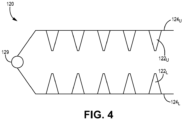
FIG. 4 is a simplified illustration of an alternative spikedarray 120, shown as a two-sided pressing apparatus.Spiked array 120 includes upper backplate 124U and lower backplate 124L with respective upper andlower spikes 122U and 122L (collectively referred to as "spikes 122").Spikes spikes 22 discussed above. Backplate 124U and 124L are connected to hinge 129, and one or both backplates may be movable abouthinge 129. In an alternative embodiment, one backplate (e.g., lower backplate 124L) can be fixed, while the other backplate (e.g., upper backplate 124U) can be moveable abouthinge 129.Spiked array 120 can be used to perforate generally planar segments ofpreform 10, and need not be guided byholes 18 oftooling 14. This is due to the fact thatupper spikes 122U are aligned with correspondinglower spikes 122L.Spiked array 120 may be preferable for quickly perforating relatively large areas (e.g., ~ 1.0 ft2 (~0.09 m2)) of woven fabric. Additionally, sincespiked array 120 can be used without tooling 14, the layout of upper and/orlower spikes holes 18, and can be arranged in various array patterns, such as square, staggered, etc. Although shown with moreconical spikes 122, spikedarray 120 can additionally and/or alternatively includes spikes similar to those shown inFIG. 2B . -
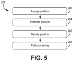
FIG. 5 is a method flowchart illustrating select steps ofmethod 200 for preparing a perforated preform, such aspreform 10 ofFIG. 3 , for use in a CMC.FIG. 6 is a simplified cross-sectional view of a section ofCMC 332 formed usingmethod 200.Method 200 is discussed together withFIGS. 1-4 and6 . - At
step 202, a net shape or near-net shape preform (e.g., preform 10) can be arranged. Such a preform can include various layers of woven fiber plies, braids, etc., and can further include a polymer-based binder or tackifier such that the underlying ceramic fabric is wet and somewhat pliable. - At
step 204, the preform can be perforated with a spiked array to form a perforated preform. In a first example using spikedarray 20, preform 10 must first be mounted ongraphite tooling 14.Spikes 22 can be aligned withholes 18 and inserted intopreform 10 to the midplane. If using only a single spikedarray 20, spikes 22 can be removed and aligned withholes 18 on the other (unperforated) side ofpreform 10 and inserted to reach the midplane such that the hourglass voids ofFIG. 3 are formed. If using multiple spikedarrays 20, spikes 22 can be inserted more or less simultaneously in an aligned manner. In a second example usingspiked array 120, step 204 can include placing a portion of the preform into the apparatus and bringing upper and lower backplates 124U and 124L together such thatcorresponding spikes perforated preform 10 can then be subsequently placed in requisite tooling in preparation forstep 206. - In either the first or second example, spikes 22, 122 are inserted in such manner as to push apart, rather than break or fray the ceramic tows. The prior application of a polymer-based binder facilitates the ability of the ceramic tows to move and bend away from the spikes, as necessary. The preform can be dried and/or debulked via one or a combination of heat and pressure applied after the insertion of spikes, which can preferably remain in place during the drying step to prevent distortion of the shape of
voids 30A and/or 30B, but may be removed in some cases. - At
step 206, preform can undergo matrix formation and densification within a reaction chamber using CVI. As is shown inFIG. 3 ,voids 30A and/or 30B inperforated preform 10 align withholes 18 ingraphite tooling 14, which gives the reactant vapors access tovoids 30A and/or 30B. During densification, the fabric layers ofperforated preform 10 are infiltrated by the reactant vapors, and a gaseous precursor deposits on the underlying fibers. The matrix material can be SiC or other suitable ceramic material. Densification is carried out until the resulting CMC has reached the desired residual porosity. If not previously burned off/decomposed, for example, during debulking, any polymer or ceramic contaminants fromspikes preform 10 will burn off and/or decompose duringstep 206. - Because of the hourglass geometry of
voids 30A and/or 30B, the matrix can deposit in an inside-out manner, referring directionally from the midplane to anouter surface 12. The widening in the outward direction due to the larger base diameter d1 and/or d3 prevents "canning off of the preform region near the midplane, where the matrix deposits too quickly near the outer surface of the preform and prevents vapors from accessing the midplane region. This can lead to asymmetrical densification with an undesirably porous midplane region compared to sufficiently densified outer surfaces.CMC 332 is shown inFIG. 6 withmatrix 334 deposited wherevoids 30A and/or 30B ofpreform 10 had been. Although shown somewhat exaggeratedly concentrated invoids 30A and/or 30B, it should be understood thatmatrix 334 deposits in and around fibers ofpreform 10 in a generally uniform manner. In CMCs formed from non-perforated preforms, or even those with cylindrical/straight holes, the final inter-tow porosity can range from 10% to 15% with a total porosity of over 20%. However, the disclosed perforated preforms can be used to form CMCs (e.g., CMC 332) with a final inter-tow porosity of less than 10% such that the total porosity of the CMC is less than 20%. - At
step 208, various post-processing steps can be performed, such as the application of one or more protective coatings (e.g., environmental and/or thermal barrier coatings). A bond coat can also be applied to facilitate bonding between the CMC and a protective coating. Other protective coatings, especially those renderingCMC 332 suitable for use in a gas turbine engine environment, are contemplated herein. - A CMC formed with the disclosed perforated preforms can be incorporated into aerospace, maritime, or industrial equipment, to name a few, non-limiting examples.
- The following are non-exclusive descriptions of possible embodiments of the present invention.
- A method of preparing a fibrous preform for use in a ceramic matrix composite comprises arranging the preform from a woven ceramic material, the preform comprising a pair of opposing outer surfaces and a midplane disposed between the pair of opposing outer surfaces, and perforating the preform with a spiked array to form a perforated preform. The perforated preform comprises a plurality of hourglass-shaped voids extending through a thickness of the preform.
- The method of the preceding paragraph can optionally include, additionally and/or alternatively, any one or more of the following features, configurations and/or additional components:
The above method can further include, prior to perforating the preform, laying-up the preform on tooling, the tooling comprising a first plate along one outer surface of the pair of opposing outer surfaces, and a plurality of holes through the plate. - In any of the above methods, the first plate can be formed from graphite.
- In any of the above methods, perforating the preform can further include aligning a plurality of spikes of the spiked array with the plurality of holes, and pressing the plurality of spikes of the spiked array into the preform via the plurality of holes.
- In any of the above methods, pressing the plurality of spikes of the spiked array into the preform can include pressing the plurality of spikes through the one outer surface to the midplane of the preform.
- In any of the above methods, the spiked array can be a two-sided pressing apparatus, and perforating the preform can further include placing the preform between a plurality of upper and lower spikes of the spiked array, and pressing the upper and lower spikes into the preform.
- In any of the above methods, arranging the preform can further include applying a polymer material to the preform to wet the preform.
- Any of the above methods can further include after perforating the preform, applying at least one of heat or pressure to dry the preform.
- Any of the above methods can further include forming the ceramic matrix composite by densifying the perforated preform using chemical vapor infiltration.
- Any of the above methods can further include applying at least one of a thermal barrier coating and an environmental barrier coating to the ceramic matrix composite.
- A fibrous preform comprises an arrangement of woven ceramic material, a pair of oppositely disposed outer surfaces defining a thickness therebetween, a midplane disposed between the pair of oppositely disposed surfaces, and a plurality of hourglass-shaped voids extending through the thickness.
- The preform of the preceding paragraph can optionally include, additionally and/or alternatively, any one or more of the following features, configurations and/or additional components:
In the above preform, the woven ceramic material can include silicon carbide. - In any of the above preforms, each of the plurality of hourglass-shaped voids can have at least one of linear or curved sides.
- In any of the above preforms, a distance from a center of a first void of the hourglass-shaped voids to a center of a second, adjacent hourglass-shaped voids can range from 1.6 x 10⁻¹ mm to 7.62 mm.
- In any of the above preforms, a diameter at a widest point of one of the plurality of hourglass-shaped voids can range from 1.0 x 10⁻¹ mm to 1.0 mm.
- In any of the above preforms, a diameter at a narrowest point of the one of the plurality of hourglass-shaped voids can range from 1.1 to 10 times less than the diameter at the widest point.
- A ceramic matrix composite can include any of the above preforms, and a ceramic matrix deposited on and around the woven ceramic material and filling the plurality of hourglass-shaped voids.
- The above ceramic matrix composite can further include an inter-tow porosity below 10%.
- In any of the above ceramic matrix composites, the ceramic matrix can include silicon carbide.
- Any of the above ceramic matrix composites can further include at least one of a thermal barrier coating and an environmental barrier coating.
- While the invention has been described with reference to an exemplary embodiment(s), it will be understood by those skilled in the art that various changes may be made and equivalents may be substituted for elements thereof without departing from the scope of the invention. In addition, many modifications may be made to adapt a particular situation or material to the teachings of the invention without departing from the essential scope thereof. Therefore, it is intended that the invention not be limited to the particular embodiment(s) disclosed, but that the invention will include all embodiments falling within the scope of the appended claims.
Claims (15)
- A method of preparing a fibrous preform (10) for use in a ceramic matrix composite (332), the method comprising:arranging the preform (10) from a woven ceramic material, the preform (10) comprising a pair of opposing outer surfaces (12) and a midplane (M) disposed between the pair of opposing outer surfaces (12); andperforating the preform (10) with a spiked array (20; 20A; 20B; 120) to form a perforated preform (10), the perforated preform (10) comprising:
a plurality of hourglass-shaped voids (30A; 30B) extending through a thickness (T) of the preform (10). - The method of claim 1 and further comprising: prior to perforating the preform (10), laying-up the preform (10) on tooling (14), the tooling (14) comprising a first plate (16) along one outer surface (12) of the pair of opposing outer surfaces (12), and a plurality of holes (18) through the first plate (16).
- The method of claim 2, wherein the first plate (16) is formed from graphite.
- The method of claim 2 or 3, wherein perforating the preform (10) comprises:aligning a plurality of spikes (22; 22A; 22B) of the spiked array (20; 20A; 20B) with the plurality of holes (18); andpressing the plurality of spikes (22; 22A; 22B) of the spiked array (20; 20A; 20B) into the preform (10) via the plurality of holes (18).
- The method of claim 4, wherein pressing the plurality of spikes (22; 22A; 22B) of the spiked array (20; 20A; 20B) into the preform (10) comprising pressing the plurality of spikes (22; 22A; 22B) through the one outer surface (12) to the midplane (M) of the preform (10).
- The method of claim 1, wherein the spiked array (120) is a two-sided pressing apparatus (120), and wherein perforating the preform (10) further comprises:placing the preform (10) between a plurality of upper and lower spikes (122U, 122L) of the spiked array (120); andpressing the upper and lower spikes (122U, 122L) into the preform (10).
- The method of any preceding claim, wherein arranging the preform (10) further comprises: applying a polymer material to the preform (10) to wet the preform (10).
- The method of claim 7, and further comprising: after perforating the preform (10), applying at least one of heat or pressure to dry the preform (10).
- The method of any preceding claim and further comprising:forming the ceramic matrix composite (332) by densifying the perforated preform (10) using chemical vapor infiltration; and optionallyapplying at least one of a thermal barrier coating and an environmental barrier coating to the ceramic matrix composite (332).
- A fibrous preform (10) comprising:an arrangement of woven ceramic material;a pair of oppositely disposed outer surfaces (12) defining a thickness (T) therebetween;a midplane (M) disposed between the pair of oppositely disposed surfaces (12); anda plurality of hourglass-shaped voids (30A; 30B) extending through the thickness (T).
- The preform (10) of claim 10, wherein the woven ceramic material comprises silicon carbide.
- The preform (10) of claim 10 or 11, wherein each of the plurality of hourglass-shaped voids (30A; 30B) has at least one of linear or curved sides.
- The preform (10) of any of claims 10 to 12, wherein a distance (DV) from a center of a first void (30A; 30B) of the hourglass-shaped voids (30A; 30B) to a center of a second, adjacent hourglass-shaped void (30A; 30B) ranges from 1.6 x 10⁻¹ mm to 7.62 mm.
- The preform (10) of any of claims 10 to 13, wherein a diameter (d1; d3) at a widest point of one of the plurality of hourglass-shaped voids (30A; 30B) ranges from 1.0 x 10⁻¹ mm to 1.0 mm, wherein a diameter (d2; d4) at a narrowest point of the one of the plurality of hourglass-shaped voids (30A; 30B) optionally ranges from 1.1 to 10 times less than the diameter (d1; d3) at the widest point.
- A ceramic matrix composite (332) comprising:the preform (10) of any of claims 10 to 14; anda ceramic matrix (334) deposited on and around the woven ceramic material and filling the plurality of hourglass-shaped voids (30A; 30B);wherein the ceramic matrix composite (332) optionally further comprises: an inter-tow porosity below 10%,wherein the ceramic matrix (334) optionally comprises silicon carbide,wherein the ceramic matrix composite (332) optionally further comprises: at least one of a thermal barrier coating and an environmental barrier coating.
Applications Claiming Priority (1)
| Application Number | Priority Date | Filing Date | Title |
|---|---|---|---|
| US202263348782P | 2022-06-03 | 2022-06-03 |
Publications (2)
| Publication Number | Publication Date |
|---|---|
| EP4286127A1 true EP4286127A1 (en) | 2023-12-06 |
| EP4286127B1 EP4286127B1 (en) | 2025-11-19 |
Family
ID=86692792
Family Applications (1)
| Application Number | Title | Priority Date | Filing Date |
|---|---|---|---|
| EP23177242.7A Active EP4286127B1 (en) | 2022-06-03 | 2023-06-05 | A fibrous preform comprising a plurality of hourglass-shaped voids |
Country Status (2)
| Country | Link |
|---|---|
| US (1) | US20230391680A1 (en) |
| EP (1) | EP4286127B1 (en) |
Families Citing this family (2)
| Publication number | Priority date | Publication date | Assignee | Title |
|---|---|---|---|---|
| US12473236B2 (en) * | 2023-10-20 | 2025-11-18 | Rtx Corporation | Internal tooling configuration for the creation of z-channels in woven ceramic matrix composite preforms |
| US12552085B2 (en) | 2023-10-20 | 2026-02-17 | Rtx Corporation | Z-channeling into a preform via needle perforation in a stand-alone tool |
Citations (3)
| Publication number | Priority date | Publication date | Assignee | Title |
|---|---|---|---|---|
| US8192662B2 (en) * | 2004-03-30 | 2012-06-05 | Toray Industries, Inc. | Processes for producing perform and FRP |
| US9475254B2 (en) * | 2009-10-23 | 2016-10-25 | Hexcel Reinforcements | Multiaxial stack rigidly connected by means of weld points applied by means of inserted thermoplastic webs |
| US10850456B2 (en) * | 2016-11-25 | 2020-12-01 | Safran Aircraft Engines | Method of fabricating an airfoil element out of composite material and having metal reinforcement fastened by riveting |
Family Cites Families (4)
| Publication number | Priority date | Publication date | Assignee | Title |
|---|---|---|---|---|
| US10618848B2 (en) * | 2013-09-20 | 2020-04-14 | General Electric Company | Ceramic matrix composites made by chemical vapor infiltration and methods of manufacture thereof |
| US10894746B2 (en) * | 2016-10-19 | 2021-01-19 | Rolls-Royce Corporation | Ceramic matrix composite reinforced material |
| EP3529059A4 (en) * | 2016-10-21 | 2020-06-03 | Mosaic Manufacturing Ltd. | ASSEMBLY ELEMENT, ASSEMBLY METHODS, AND ASSOCIATED SYSTEMS FOR ADDITIVE MANUFACTURE |
| FR3093298B1 (en) * | 2019-03-01 | 2021-03-12 | Safran | Repair or resumption of manufacture of a composite material part |
-
2023
- 2023-05-26 US US18/202,640 patent/US20230391680A1/en active Pending
- 2023-06-05 EP EP23177242.7A patent/EP4286127B1/en active Active
Patent Citations (3)
| Publication number | Priority date | Publication date | Assignee | Title |
|---|---|---|---|---|
| US8192662B2 (en) * | 2004-03-30 | 2012-06-05 | Toray Industries, Inc. | Processes for producing perform and FRP |
| US9475254B2 (en) * | 2009-10-23 | 2016-10-25 | Hexcel Reinforcements | Multiaxial stack rigidly connected by means of weld points applied by means of inserted thermoplastic webs |
| US10850456B2 (en) * | 2016-11-25 | 2020-12-01 | Safran Aircraft Engines | Method of fabricating an airfoil element out of composite material and having metal reinforcement fastened by riveting |
Also Published As
| Publication number | Publication date |
|---|---|
| US20230391680A1 (en) | 2023-12-07 |
| EP4286127B1 (en) | 2025-11-19 |
Similar Documents
| Publication | Publication Date | Title |
|---|---|---|
| EP4286127B1 (en) | A fibrous preform comprising a plurality of hourglass-shaped voids | |
| EP4344843A1 (en) | Spiked preform tooling for improved chemical vapor infiltration in ceramic matrix composites | |
| US10906205B2 (en) | Shaping equipment and facility for gas-phase chemical infiltration of fibrous preforms | |
| RU2519116C2 (en) | Method of producing complex shape parts from composites | |
| US6691393B2 (en) | Wear resistance in carbon fiber friction materials | |
| CN107043268B (en) | Sacrificial fibers for forming channels in composite materials | |
| CN101189447B (en) | Method and substrate for making composite material parts by chemical vapor infiltration densification and resulting parts | |
| EP4541535A1 (en) | Z-channeling into a preform via needle perforation in a stand-alone tool | |
| EP3326814B1 (en) | High strength laminate structure | |
| EP4454842A1 (en) | Z-channel creation in woven preform by incorporation of pin features into preform tooling | |
| JP7416470B2 (en) | System and method for coating ceramic fibers | |
| EP4446076A1 (en) | A method of forming a ceramic matrix composite, and a pin array | |
| US10934219B2 (en) | Method of increasing the uniformity of chemical vapor deposition on fibrous material through the imposition of pressure waves | |
| US11608748B2 (en) | Preform crossovers for composite airfoils | |
| US20040074075A1 (en) | Wear resistance in carbon fiber friction materials | |
| US20250136521A1 (en) | Variable z-channel hole pattern | |
| US12473236B2 (en) | Internal tooling configuration for the creation of z-channels in woven ceramic matrix composite preforms | |
| EP1568911A1 (en) | Improved wear resistance in carbon fiber friction materials | |
| EP4431483A1 (en) | Three dimensional weave with sacrifical z-fibers for improved ceramic matrix composite microstructure | |
| EP4119319B1 (en) | Method of fabric processing for improved cmc infiltration | |
| EP4477413A1 (en) | Particle enhanced ceramic matrix composite with no particles on surface plies | |
| EP4470740A1 (en) | Additively manufactured graphite tooling |
Legal Events
| Date | Code | Title | Description |
|---|---|---|---|
| PUAI | Public reference made under article 153(3) epc to a published international application that has entered the european phase |
Free format text: ORIGINAL CODE: 0009012 |
|
| STAA | Information on the status of an ep patent application or granted ep patent |
Free format text: STATUS: THE APPLICATION HAS BEEN PUBLISHED |
|
| AK | Designated contracting states |
Kind code of ref document: A1 Designated state(s): AL AT BE BG CH CY CZ DE DK EE ES FI FR GB GR HR HU IE IS IT LI LT LU LV MC ME MK MT NL NO PL PT RO RS SE SI SK SM TR |
|
| STAA | Information on the status of an ep patent application or granted ep patent |
Free format text: STATUS: REQUEST FOR EXAMINATION WAS MADE |
|
| 17P | Request for examination filed |
Effective date: 20240521 |
|
| RBV | Designated contracting states (corrected) |
Designated state(s): AL AT BE BG CH CY CZ DE DK EE ES FI FR GB GR HR HU IE IS IT LI LT LU LV MC ME MK MT NL NO PL PT RO RS SE SI SK SM TR |
|
| STAA | Information on the status of an ep patent application or granted ep patent |
Free format text: STATUS: EXAMINATION IS IN PROGRESS |
|
| 17Q | First examination report despatched |
Effective date: 20241015 |
|
| GRAP | Despatch of communication of intention to grant a patent |
Free format text: ORIGINAL CODE: EPIDOSNIGR1 |
|
| STAA | Information on the status of an ep patent application or granted ep patent |
Free format text: STATUS: GRANT OF PATENT IS INTENDED |
|
| INTG | Intention to grant announced |
Effective date: 20250617 |
|
| GRAS | Grant fee paid |
Free format text: ORIGINAL CODE: EPIDOSNIGR3 |
|
| GRAA | (expected) grant |
Free format text: ORIGINAL CODE: 0009210 |
|
| STAA | Information on the status of an ep patent application or granted ep patent |
Free format text: STATUS: THE PATENT HAS BEEN GRANTED |
|
| AK | Designated contracting states |
Kind code of ref document: B1 Designated state(s): AL AT BE BG CH CY CZ DE DK EE ES FI FR GB GR HR HU IE IS IT LI LT LU LV MC ME MK MT NL NO PL PT RO RS SE SI SK SM TR |
|
| REG | Reference to a national code |
Ref country code: CH Ref legal event code: F10 Free format text: ST27 STATUS EVENT CODE: U-0-0-F10-F00 (AS PROVIDED BY THE NATIONAL OFFICE) Effective date: 20251119 Ref country code: GB Ref legal event code: FG4D |
|
| REG | Reference to a national code |
Ref country code: DE Ref legal event code: R096 Ref document number: 602023008692 Country of ref document: DE |
|
| REG | Reference to a national code |
Ref country code: IE Ref legal event code: FG4D |
|
| REG | Reference to a national code |
Ref country code: NL Ref legal event code: MP Effective date: 20251119 |
|
| PG25 | Lapsed in a contracting state [announced via postgrant information from national office to epo] |
Ref country code: ES Free format text: LAPSE BECAUSE OF FAILURE TO SUBMIT A TRANSLATION OF THE DESCRIPTION OR TO PAY THE FEE WITHIN THE PRESCRIBED TIME-LIMIT Effective date: 20251119 |
|
| REG | Reference to a national code |
Ref country code: LT Ref legal event code: MG9D |
|
| PG25 | Lapsed in a contracting state [announced via postgrant information from national office to epo] |
Ref country code: NO Free format text: LAPSE BECAUSE OF FAILURE TO SUBMIT A TRANSLATION OF THE DESCRIPTION OR TO PAY THE FEE WITHIN THE PRESCRIBED TIME-LIMIT Effective date: 20260219 |
|
| PG25 | Lapsed in a contracting state [announced via postgrant information from national office to epo] |
Ref country code: FI Free format text: LAPSE BECAUSE OF FAILURE TO SUBMIT A TRANSLATION OF THE DESCRIPTION OR TO PAY THE FEE WITHIN THE PRESCRIBED TIME-LIMIT Effective date: 20251119 Ref country code: HR Free format text: LAPSE BECAUSE OF FAILURE TO SUBMIT A TRANSLATION OF THE DESCRIPTION OR TO PAY THE FEE WITHIN THE PRESCRIBED TIME-LIMIT Effective date: 20251119 Ref country code: AT Free format text: LAPSE BECAUSE OF FAILURE TO SUBMIT A TRANSLATION OF THE DESCRIPTION OR TO PAY THE FEE WITHIN THE PRESCRIBED TIME-LIMIT Effective date: 20251119 |
|
| REG | Reference to a national code |
Ref country code: AT Ref legal event code: MK05 Ref document number: 1858477 Country of ref document: AT Kind code of ref document: T Effective date: 20251119 |
|
| PG25 | Lapsed in a contracting state [announced via postgrant information from national office to epo] |
Ref country code: NL Free format text: LAPSE BECAUSE OF FAILURE TO SUBMIT A TRANSLATION OF THE DESCRIPTION OR TO PAY THE FEE WITHIN THE PRESCRIBED TIME-LIMIT Effective date: 20251119 |
|
| PG25 | Lapsed in a contracting state [announced via postgrant information from national office to epo] |
Ref country code: RS Free format text: LAPSE BECAUSE OF FAILURE TO SUBMIT A TRANSLATION OF THE DESCRIPTION OR TO PAY THE FEE WITHIN THE PRESCRIBED TIME-LIMIT Effective date: 20260219 |
|
| PG25 | Lapsed in a contracting state [announced via postgrant information from national office to epo] |
Ref country code: IS Free format text: LAPSE BECAUSE OF FAILURE TO SUBMIT A TRANSLATION OF THE DESCRIPTION OR TO PAY THE FEE WITHIN THE PRESCRIBED TIME-LIMIT Effective date: 20260319 |
|
| PG25 | Lapsed in a contracting state [announced via postgrant information from national office to epo] |
Ref country code: PT Free format text: LAPSE BECAUSE OF FAILURE TO SUBMIT A TRANSLATION OF THE DESCRIPTION OR TO PAY THE FEE WITHIN THE PRESCRIBED TIME-LIMIT Effective date: 20260319 |
|
| PG25 | Lapsed in a contracting state [announced via postgrant information from national office to epo] |
Ref country code: PL Free format text: LAPSE BECAUSE OF FAILURE TO SUBMIT A TRANSLATION OF THE DESCRIPTION OR TO PAY THE FEE WITHIN THE PRESCRIBED TIME-LIMIT Effective date: 20251119 |
|
| PG25 | Lapsed in a contracting state [announced via postgrant information from national office to epo] |
Ref country code: LV Free format text: LAPSE BECAUSE OF FAILURE TO SUBMIT A TRANSLATION OF THE DESCRIPTION OR TO PAY THE FEE WITHIN THE PRESCRIBED TIME-LIMIT Effective date: 20251119 |
|
| PG25 | Lapsed in a contracting state [announced via postgrant information from national office to epo] |
Ref country code: BG Free format text: LAPSE BECAUSE OF FAILURE TO SUBMIT A TRANSLATION OF THE DESCRIPTION OR TO PAY THE FEE WITHIN THE PRESCRIBED TIME-LIMIT Effective date: 20251119 |