EP4286110A1 - Wearable instrument - Google Patents
Wearable instrument Download PDFInfo
- Publication number
- EP4286110A1 EP4286110A1 EP21931753.4A EP21931753A EP4286110A1 EP 4286110 A1 EP4286110 A1 EP 4286110A1 EP 21931753 A EP21931753 A EP 21931753A EP 4286110 A1 EP4286110 A1 EP 4286110A1
- Authority
- EP
- European Patent Office
- Prior art keywords
- output
- judgment
- unit
- wearable instrument
- user
- Prior art date
- Legal status (The legal status is an assumption and is not a legal conclusion. Google has not performed a legal analysis and makes no representation as to the accuracy of the status listed.)
- Withdrawn
Links
Images


Classifications
-
- B—PERFORMING OPERATIONS; TRANSPORTING
- B25—HAND TOOLS; PORTABLE POWER-DRIVEN TOOLS; MANIPULATORS
- B25J—MANIPULATORS; CHAMBERS PROVIDED WITH MANIPULATION DEVICES
- B25J19/00—Accessories fitted to manipulators, e.g. for monitoring, for viewing; Safety devices combined with or specially adapted for use in connection with manipulators
- B25J19/02—Sensing devices
-
- B—PERFORMING OPERATIONS; TRANSPORTING
- B25—HAND TOOLS; PORTABLE POWER-DRIVEN TOOLS; MANIPULATORS
- B25J—MANIPULATORS; CHAMBERS PROVIDED WITH MANIPULATION DEVICES
- B25J13/00—Controls for manipulators
- B25J13/06—Control stands, e.g. consoles, switchboards
-
- B—PERFORMING OPERATIONS; TRANSPORTING
- B25—HAND TOOLS; PORTABLE POWER-DRIVEN TOOLS; MANIPULATORS
- B25J—MANIPULATORS; CHAMBERS PROVIDED WITH MANIPULATION DEVICES
- B25J13/00—Controls for manipulators
- B25J13/02—Hand grip control means
-
- B—PERFORMING OPERATIONS; TRANSPORTING
- B25—HAND TOOLS; PORTABLE POWER-DRIVEN TOOLS; MANIPULATORS
- B25J—MANIPULATORS; CHAMBERS PROVIDED WITH MANIPULATION DEVICES
- B25J19/00—Accessories fitted to manipulators, e.g. for monitoring, for viewing; Safety devices combined with or specially adapted for use in connection with manipulators
- B25J19/06—Safety devices
-
- B—PERFORMING OPERATIONS; TRANSPORTING
- B25—HAND TOOLS; PORTABLE POWER-DRIVEN TOOLS; MANIPULATORS
- B25J—MANIPULATORS; CHAMBERS PROVIDED WITH MANIPULATION DEVICES
- B25J9/00—Program-controlled manipulators
- B25J9/16—Program controls
- B25J9/1674—Program controls characterised by safety, monitoring, diagnostic
-
- G—PHYSICS
- G01—MEASURING; TESTING
- G01C—MEASURING DISTANCES, LEVELS OR BEARINGS; SURVEYING; NAVIGATION; GYROSCOPIC INSTRUMENTS; PHOTOGRAMMETRY OR VIDEOGRAMMETRY
- G01C21/00—Navigation; Navigational instruments not provided for in groups G01C1/00 - G01C19/00
- G01C21/10—Navigation; Navigational instruments not provided for in groups G01C1/00 - G01C19/00 by using measurements of speed or acceleration
- G01C21/12—Navigation; Navigational instruments not provided for in groups G01C1/00 - G01C19/00 by using measurements of speed or acceleration executed aboard the object being navigated; Dead reckoning
- G01C21/16—Navigation; Navigational instruments not provided for in groups G01C1/00 - G01C19/00 by using measurements of speed or acceleration executed aboard the object being navigated; Dead reckoning by integrating acceleration or speed, i.e. inertial navigation
-
- G—PHYSICS
- G06—COMPUTING OR CALCULATING; COUNTING
- G06F—ELECTRIC DIGITAL DATA PROCESSING
- G06F3/00—Input arrangements for transferring data to be processed into a form capable of being handled by the computer; Output arrangements for transferring data from processing unit to output unit, e.g. interface arrangements
- G06F3/01—Input arrangements or combined input and output arrangements for interaction between user and computer
- G06F3/011—Arrangements for interaction with the human body, e.g. for user immersion in virtual reality
-
- G—PHYSICS
- G08—SIGNALLING
- G08B—SIGNALLING SYSTEMS, e.g. PERSONAL CALLING SYSTEMS; ORDER TELEGRAPHS; ALARM SYSTEMS
- G08B21/00—Alarms responsive to a single specified undesired or abnormal condition and not otherwise provided for
- G08B21/02—Alarms for ensuring the safety of persons
- G08B21/04—Alarms for ensuring the safety of persons responsive to non-activity, e.g. of elderly persons
-
- G—PHYSICS
- G08—SIGNALLING
- G08B—SIGNALLING SYSTEMS, e.g. PERSONAL CALLING SYSTEMS; ORDER TELEGRAPHS; ALARM SYSTEMS
- G08B21/00—Alarms responsive to a single specified undesired or abnormal condition and not otherwise provided for
- G08B21/02—Alarms for ensuring the safety of persons
- G08B21/04—Alarms for ensuring the safety of persons responsive to non-activity, e.g. of elderly persons
- G08B21/0407—Alarms for ensuring the safety of persons responsive to non-activity, e.g. of elderly persons based on behaviour analysis
- G08B21/0415—Alarms for ensuring the safety of persons responsive to non-activity, e.g. of elderly persons based on behaviour analysis detecting absence of activity per se
-
- G—PHYSICS
- G08—SIGNALLING
- G08B—SIGNALLING SYSTEMS, e.g. PERSONAL CALLING SYSTEMS; ORDER TELEGRAPHS; ALARM SYSTEMS
- G08B21/00—Alarms responsive to a single specified undesired or abnormal condition and not otherwise provided for
- G08B21/02—Alarms for ensuring the safety of persons
- G08B21/04—Alarms for ensuring the safety of persons responsive to non-activity, e.g. of elderly persons
- G08B21/0438—Sensor means for detecting
- G08B21/0446—Sensor means for detecting worn on the body to detect changes of posture, e.g. a fall, inclination, acceleration, gait
-
- G—PHYSICS
- G05—CONTROLLING; REGULATING
- G05B—CONTROL OR REGULATING SYSTEMS IN GENERAL; FUNCTIONAL ELEMENTS OF SUCH SYSTEMS; MONITORING OR TESTING ARRANGEMENTS FOR SUCH SYSTEMS OR ELEMENTS
- G05B2219/00—Program-control systems
- G05B2219/30—Nc systems
- G05B2219/37—Measurements
- G05B2219/37134—Gyroscope
-
- G—PHYSICS
- G05—CONTROLLING; REGULATING
- G05B—CONTROL OR REGULATING SYSTEMS IN GENERAL; FUNCTIONAL ELEMENTS OF SUCH SYSTEMS; MONITORING OR TESTING ARRANGEMENTS FOR SUCH SYSTEMS OR ELEMENTS
- G05B2219/00—Program-control systems
- G05B2219/30—Nc systems
- G05B2219/50—Machine tool, machine tool null till machine tool work handling
- G05B2219/50198—Emergency stop
Definitions
- the present invention relates to a wearable instrument.
- Patent Document 1 discloses an enabling switch used in a safety device of equipment such as a teach pendant of a robot or a machine tool.
- Patent Literature 1 Japanese Patent No. 4085686
- the present invention has been made in view of the circumstances described above, and an object of the present invention is to provide a technique that enables a user to use both hands while ensuring safety during work.
- a wearable instrument is a wearable instrument configured to be wearable by a user, the wearable instrument including an inertial sensor, a judgment unit configured to judge whether an output value of the inertial sensor meets a predetermined condition, and an output unit configured to output an operation permission signal for instructing a control device configured to control operation of a machine to permit operation of the machine in a case in which the output value meets the predetermined condition.
- the output unit In a case in which the output value of the inertial sensor meets the predetermined condition, the output unit outputs the operation permission signal for instructing the control device to permit operation of the machine.
- the control device continues operation of the machine. For example, in a case in which the user makes a sudden movement to avoid contact or collision with the machine, the output value of the inertial sensor does not meet the predetermined condition and the output unit does not output the operation permission signal to the control device.
- the operation permission signal is no longer input to the control device, and the control device stops operation of the machine.
- the wearable instrument By wearing the wearable instrument, the user does not need to hold the wearable instrument with one or both hands, and the user can use both hands during work. Accordingly, the user can use both hands while ensuring safety during work.
- the judgment unit may judge whether the output value meets the predetermined condition by executing one of a plurality of types of judgment algorithms.
- the wearable instrument according to the present disclosure may include a switching unit configured to switch a state of the output unit to active or inactive.
- the output unit may output the operation permission signal to the control device in a case in which the state of the output unit is active and the output value meets the predetermined condition.
- the output unit does not output the operation permission signal to the control device in a case in which the state of the output unit is inactive.
- the judgment unit may make a judgment that the user is not wearing the wearable instrument in a case in which the output value does not fluctuate for a predetermined period, and the switching unit may set the state of the output unit to inactive in a case in which the judgment unit makes a judgment that the user is not wearing the wearable instrument.
- the wearable instrument according to the present disclosure may further include a vital sensor configured to acquire vital data of the user, the judgment unit may make a judgment that the user is not wearing the wearable instrument in a case in which the vital sensor does not acquire the vital data, and the switching unit may set the state of the output unit to inactive in a case in which the judgment unit makes a judgment that the user is not wearing the wearable instrument.
- a vital sensor configured to acquire vital data of the user
- the judgment unit may make a judgment that the user is not wearing the wearable instrument in a case in which the vital sensor does not acquire the vital data
- the switching unit may set the state of the output unit to inactive in a case in which the judgment unit makes a judgment that the user is not wearing the wearable instrument.
- the wearable instrument according to the present disclosure may further include a notification unit configured to issue a notification of first information indicating that the user is wearing the wearable instrument or second information indicating that the user is not wearing the wearable instrument, and the notification unit may issue a notification of the first information in a case in which the judgment unit makes a judgment that the user is wearing the wearable instrument, and issue a notification of the second information in a case in which the judgment unit makes a judgment that the user is not wearing the wearable instrument.
- the wearable instrument may further include a diagnostic unit configured to make a diagnosis as to whether the inertial sensor is operating normally, and the notification unit may issue a notification of information indicating that the inertial sensor is operating normally in a case in which the diagnostic unit makes a diagnosis that the inertial sensor is operating normally, and issue a notification of information indicating that the inertial sensor is not operating normally in a case in which the diagnostic unit makes a diagnosis that the inertial sensor is not operating normally.
- a diagnostic unit configured to make a diagnosis as to whether the inertial sensor is operating normally
- the notification unit may issue a notification of information indicating that the inertial sensor is operating normally in a case in which the diagnostic unit makes a diagnosis that the inertial sensor is operating normally, and issue a notification of information indicating that the inertial sensor is not operating normally in a case in which the diagnostic unit makes a diagnosis that the inertial sensor is not operating normally.
- the inertial sensor may be an accelerometer or an angular velocity sensor.
- the wearable instrument according to the present disclosure may include a plurality of the inertial sensors. At least one of the plurality of inertial sensors may be an accelerometer, and at least one of the plurality of inertial sensors may be an angular velocity sensor.
- the predetermined condition may include a condition that the output value is equal to or less than a threshold value or less than the threshold value.
- the predetermined condition may include a condition that a predetermined calculation is performed on the output value and a calculation value obtained by the predetermined calculation is equal to or less than a threshold value or less than the threshold value.
- the predetermined condition may include a condition that an amount of change in a current value of the output value with respect to a previous value of the output value is equal to or less than a threshold value or less than the threshold value, or that the amount of change falls within a predetermined range.
- the predetermined condition may include a condition that a predetermined calculation is performed on past data and current data of the output value, and a calculation value obtained by the predetermined calculation is equal to or less than a threshold value or less than the threshold value, or the calculation value falls within a predetermined range.
- the predetermined condition may include a condition that a predetermined calculation is performed on past data and current data of an amount of change in a current value of the output value with respect to a previous value of the output value, and a calculation value obtained by the predetermined calculation is equal to or less than a threshold value or less than the threshold value, or the calculation value falls within a predetermined range.
- the threshold value and the predetermined range may be variable.
- FIG. 1 is a block diagram schematically illustrating a configuration of a control system including a wearable instrument 1 according to an embodiment of the present invention.
- the wearable instrument 1 can be worn by a user 2 such as a worker, and is worn by the user 2 when the user 2 performs work such as maintenance near a machine 3 such as a robot.
- the wearable instrument 1 can be worn on the wrist, arm, foot, head, or another body part of the user 2.
- the machine 3 and a control device 4 that controls operation of the machine 3 are installed on a workbench 5.
- the wearable instrument 1 and the control device 4 communicate with each other in a wired or wireless manner. Communication between the wearable instrument 1 and the control device 4 includes transmission of information by a digital input/output (I/O) signal.
- the wearable instrument 1 may be configured to allow selection as to whether communication with the control device 4 is performed by a wired or wireless method. An optimum connection method for the control device 4 or an optimum connection method for each environment in which the control device 4 is installed is selected, and then communication between the wearable instrument 1 and the control device 4 is performed.
- the user 2 When the user 2 performs work such as maintenance near the machine 3 as illustrated in FIG. 1 , it is necessary to ensure the safety of the user 2.
- the user 2 puts on the wearable instrument 1 before performing the work such as maintenance. For example, in a case in which the user 2 comes too close to the machine 3, the user 2 tends to make more sudden movements (abnormal movements) than normal during the work such as maintenance to avoid contact or collision with the machine 3. This abnormal movement of the user 2 is detected and operation of the machine 3 is stopped. Thus, contact or collision between the user 2 and the machine 3 is avoided.
- a technique of detecting an abnormal movement of the user 2 will be described.
- FIG. 2 is a hardware configuration diagram of the wearable instrument 1.
- the wearable instrument 1 includes a sensor unit 10, a control unit 20, an output unit 30, a display unit 40, and an operation unit 50.
- the sensor unit 10 includes a plurality of inertial sensors 11 (11A and 11B) and a diagnostic circuit 12.
- the sensor unit 10 processes output values of the inertial sensors 11A, 11B and transmits the output values to the control unit 20.
- the inertial sensors 11A, 11B may each be an accelerometer that detects acceleration in the X-axis direction, the Y-axis direction, and the Z-axis direction.
- the inertial sensors 11A, 11B may each be an angular velocity sensor (gyro sensor) that detects rotational angular velocities respectively about the three axes of a roll axis, a pitch axis, and a roll axis. At least one of the plurality of inertial sensors 11 may be an angular velocity sensor. At least one of the plurality of inertial sensors 11 may be an angular velocity sensor.
- FIG. 2 illustrates an example of a configuration in which the sensor unit 10 includes the two inertial sensors 11 (11A, 11B), but the number of the inertial sensors 11 may be increased or decreased.
- the sensor unit 10 may include one inertial sensor 11 or may include three or more inertial sensors 11.
- the diagnostic circuit 12 makes a diagnosis as to whether the inertial sensors 11A, 11B are operating normally, and displays the result of the diagnosis on the display unit 40.
- the diagnostic circuit 12 is an example of a diagnostic unit.
- the control unit 20 controls each unit of the wearable instrument 1 and performs signal processing, arithmetic processing, and the like.
- the control unit 20 includes a plurality of microprocessor units (MPUs) 21 (21A and 21B) and a plurality of memories 22 (22A and 22B).
- the MPUs 21A, 21B may monitor each other.
- the memories 22A, 22B are each a random access memory (RAM), a nonvolatile storage device (read-only memory (ROM), flash memory), or the like.
- Functions of the control unit 20 may be provided by the MPU 21A deploying a program stored in the memory 22A and executing the program.
- the functions of the control unit 20 may be provided by the MPU 21B deploying a program stored in the memory 22B and executing the program.
- control unit 20 may be configured by a circuit such as an application-specific integrated circuit (ASIC) or a field-programmable gate array (FPGA).
- FIG. 2 illustrates an example of a configuration in which the control unit 20 includes the two MPUs 21 (21A and 21B) and the two memories 22 (22A and 22B), but the number of the MPUs 21 and the number of the memories 22 may be increased or decreased.
- the control unit 20 may include one MPU 21 or may have three or more MPUs 21.
- the control unit 20 may include one memory 22 or may include three or more memories 22. Further, the memory 22 need not be provided in the control unit 20.
- the output unit 30 includes a plurality of output circuits 31 (31A and 31B) and a diagnostic circuit 32.
- the output unit 30 outputs data and signals processed by the control unit 20 under the control of the control unit 20.
- the functions of the output unit 30 may be provided by the output circuit 31A performing various kinds of processes under the control of the control unit 20.
- the functions of the output unit 30 may be provided by the output circuit 31B performing various kinds of processes under the control of the control unit 20.
- FIG. 2 illustrates an example of a configuration in which the output unit 30 includes the two output circuits 31 (31A and 31B), but the number of the output circuit 31 may be increased or decreased.
- the output unit 30 may include one output circuit 31, or may include three or more output circuits 31.
- the diagnostic circuit 32 makes a diagnosis as to whether the output circuits 31A, 31B are operating normally, and displays the result of the diagnosis on the display unit 40.
- the display unit 40 is constituted by a liquid crystal display or another display, and displays various kinds of information. Further, the display unit 40 may have a function of notifying the user 2 by using sound, a light, an LED, or the like, on the basis of an instruction from the control unit 20.
- the operation unit 50 accepts input of various kinds of instructions from the user 2 and transmits the input information to the control unit 20.
- FIG. 3 is a functional block diagram of the control unit 20.
- the control unit 20 includes a judgment unit 60, a switching unit 70, a notification unit 80, and a storage unit 90.
- the judgment unit 60 judges whether the output value of the inertial sensor 11 meets a predetermined condition.
- the predetermined condition will be described below.
- the judgment unit 60 judges whether the output value of the inertial sensor 11A meets the predetermined condition.
- the judgment unit 60 judges whether the output value of the inertial sensor 11B meets the predetermined condition.
- the switching unit 70 switches a state of the output unit 30 to active or inactive.
- the switching unit 70 may switch the state of the output unit 30 to active or inactive on the basis of an instruction from the judgment unit 60 or the judgment result of the judgment unit 60. Further, the switching unit 70 may switch the state of the output unit 30 to active or inactive on the basis of an instruction from the user 2.
- the notification unit 80 issues a notification of various kinds of information.
- the storage unit 90 stores various kinds of data and information.
- the output unit 30 outputs an operation permission signal for instructing the control device 4 to permit operation of the machine 3.
- the control device 4 controls the operation of the machine 3 on the basis of control information stored in a storage device such as a memory in the control device 4. As described above, in a case in which the operation permission signal is input to the control device 4, the control device 4 continues operation of the machine 3.
- the output value of the inertial sensor 11 does not meet the predetermined condition, and the output unit 30 stops the output of the operation permission signal to the control device 4.
- the operation permission signal is no longer input to the control device 4, and the control device 4 stops the operation of the machine 3. Accordingly, contact or collision between the user 2 and the machine 3 is avoided, and the safety of the user 2 when the user 2 performs work such as maintenance near the machine 3 is ensured.
- the wearable instrument 1 By wearing the wearable instrument 1, the user 2 does not need to hold the wearable instrument 1 in one or both hands, and the user 2 can use both hands during work such as maintenance. Thus, the user 2 can use both hands while ensuring safety during work.
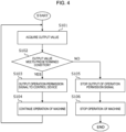
- step S101 the judgment unit 60 acquires the output value of the inertial sensor 11.
- step S102 the judgment unit 60 judges whether the output value of the inertial sensor 11 meets the predetermined condition.
- the judgment unit 60 may judge whether the output value of the inertial sensor 11 meets the predetermined condition by executing one of a plurality of types of judgment algorithms.
- the plurality of types of judgment algorithms are stored in the storage unit 90.
- the judgment unit 60 may select one of the plurality of types of judgment algorithms stored in the storage unit 90. Accordingly, the judgment unit 60 can perform an appropriate judgment process suited to the user 2 and the work environment, and the control device 4 can appropriately stop operation of the machine 3.
- first to third judgment processes based on the judgment algorithms will be described.
- the judgment unit 60 may perform the first to third judgment processes described below by machine learning using artificial intelligence (Al) technology.
- the judgment unit 60 may set a threshold value for the output value of the inertial sensor 11 and judge whether the output value of the inertial sensor 11 is equal to or less than the threshold value or less than the threshold value. Threshold values for the output values of each axis of XYZ of the inertial sensor 11 may be used, or a threshold value for a result of calculating the output value of the inertial sensor 11 as in ⁇ (x ⁇ 2 + y ⁇ 2 + z ⁇ 2) may be used.
- a threshold value for the absolute value of the output value of the inertial sensor 11 may be used. Different threshold values may be used in accordance with whether the output value of the inertial sensor 11 is positive or negative.
- the threshold value may be variably set. The threshold value may be changed in accordance with the posture of the inertial sensor 11. The threshold value may be set in consideration of variation in statistical data of the output values of the inertial sensor 11.
- the predetermined condition includes a condition that the output value of the inertial sensor 11 is equal to or less than a threshold value or less than the threshold value.
- the predetermined condition includes a condition that a predetermined calculation is performed on the output value of the inertial sensor 11, and a calculation value obtained by the predetermined calculation is equal to or less than a threshold value or less than the threshold value.
- the judgment unit 60 may judge whether an amount of change in the current value of the output value of the inertial sensor 11 with respect to the previous value of the output value of the inertial sensor 11 is equal to or less than a threshold value or less than a threshold value, or whether the amount of change falls within a predetermined range.
- the amount of change may be a ratio of the current value of the output value of the inertial sensor 11 to the previous value of the output value of the inertial sensor 11, or may be a value of difference between the previous value of the output value of the inertial sensor 11 and the current value of the output value of the inertial sensor 11.
- the threshold value and the predetermined range may be variable.
- the threshold value and the predetermined range may be set in consideration of variation in statistical data of the output values of the inertial sensor 11.
- the predetermined condition includes a condition that the amount of change in the current value of the output value of the inertial sensor 11 with respect to the previous value of the output value of the inertial sensor 11 is equal to or less than a threshold value or less than a threshold value, or that the amount of change falls within a predetermined range.
- the judgment unit 60 may perform a predetermined calculation on past data and current data of the output value of the inertial sensor 11, and judge whether a calculation value obtained by the predetermined calculation is equal to or less than a threshold value or less than the threshold value, or whether the calculation value falls within a predetermined range.
- the predetermined calculation is, for example, a moving average.
- the past data of the output value of the inertial sensor 11 includes a plurality of output values output from the inertial sensor 11 in the past.
- the judgment unit 60 may perform a predetermined calculation on the past data and latest data of the amount of change in the current value of the output value of the inertial sensor 11 with respect to the previous value of the output value of the inertial sensor 11, and judge whether a calculation value obtained by the predetermined calculation is equal to or less than a threshold value or less than a threshold value, or whether the calculation value falls within a predetermined range.
- the past data of the amount of change includes multiple amounts of change calculated from a plurality of output values output from the inertial sensor 11 in the past.
- the threshold value and the predetermined range may be variable.
- the threshold value and the predetermined range may be set in consideration of variation in statistical data of the output values of the inertial sensor 11.
- the predetermined condition includes a condition that a predetermined calculation is performed on the past data and the current data of the output value of the inertial sensor 11, and a calculation value obtained by the predetermined calculation is equal to or less than a threshold value or less than the threshold value, or the calculation value falls within a predetermined range.
- the predetermined condition includes a condition that a predetermined calculation is performed on the past data and the current data of the amount of change in the current value of the output value of the inertial sensor 11 with respect to the previous value of the output value of the inertial sensor 11, and a calculation value obtained by the predetermined calculation is equal to or less than a threshold value or less than the threshold value, or the calculation value falls within a predetermined range.
- step S102 When the output value of the inertial sensor 11 meets the predetermined condition (step S102: YES), the process proceeds to step S103.
- step S103 the output unit 30 outputs an operation permission signal for instructing the control device 4 to permit operation of the machine 3.
- step S104 the control device 4 continues operation of the machine 3.
- step S102 NO
- the process proceeds to step S105.
- step S105 the output unit 30 stops output of the operation permission signal.
- step S106 the control device 4 stops operation of the machine 3.
- the switching unit 70 switches the state of the output unit 30 from active to inactive on the basis of an instruction from the user 2. In a case in which the state of the output unit 30 is inactive, the output unit 30 does not output the operation permission signal to the control device 4.
- the switching unit 70 switches the state of the output unit 30 from inactive to active on the basis of an instruction from the user 2. For example, in a case in which the user 2 performs work near the machine 3, the user 2 switches the state of the output unit 30 from inactive to active. In a case in which the state of the output unit 30 is active and the output value of the inertial sensor 11 meets a predetermined condition, the output unit 30 outputs the operation permission signal to the control device 4. With the state of the output unit 30 switched from inactive to active, the operation of the machine 3 is stopped when the user 2 makes an abnormal movement. Thus, contact or collision between the user 2 and the machine 3 can be avoided.
- the judgment unit 60 judges whether the user 2 is wearing the wearable instrument 1. In a case in which the output value of the inertial sensor 11 does not fluctuate for a predetermined period, the judgment unit 60 makes a judgment that the user 2 is not wearing the wearable instrument 1. When the user 2 is wearing the wearable instrument 1, the output value of the inertial sensor 11 fluctuates. In a case in which the judgment unit 60 makes a judgment that the user 2 is not wearing the wearable instrument 1, the switching unit 70 sets the state of the output unit 30 to inactive. Accordingly, in a case in which the user 2 is not wearing the wearable instrument 1, the state of the output unit 30 is set to inactive, and the output unit 30 does not output the operation permission signal to the control device 4.
- the switching unit 70 may maintain the state of the output unit 30 as active. In this case, the output unit 30 does not output the operation permission signal to the control device 4. That is, in a case in which the judgment unit 60 makes a judgment that the user 2 is not wearing the wearable instrument 1, the output unit 30 does not output the operation permission signal to the control device 4.
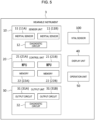
- the wearable instrument 1 may include a vital sensor 100 that acquires vital data (biological data) of the user 2.
- FIG. 5 is a hardware configuration diagram of the wearable instrument 1.
- the sensor unit 10 may include the vital sensor 100.
- the judgment unit 60 makes a judgment that the user 2 is not wearing the wearable instrument 1.
- the vital data is, for example, a pulse of the user 2.
- the judgment unit 60 can judge whether the user 2 is wearing the wearable instrument 1 by using the vital data.
- the switching unit 70 sets the state of the output unit 30 to inactive.
- the switching unit 70 may maintain the state of the output unit 30 as active. In this case, the output unit 30 does not output the operation permission signal to the control device 4. That is, in a case in which the judgment unit 60 makes a judgment that the user 2 is not wearing the wearable instrument 1, the output unit 30 does not output the operation permission signal to the control device 4.
- the notification unit 80 notifies the user of information (first information) indicating that the user 2 is wearing the wearable instrument 1 or information (second information) indicating that the user 2 is not wearing the wearable instrument 1.
- the notification unit 80 issues a notification of the first information.
- the notification unit 80 issues a notification of the second information.
- the notification unit 80 may display the first information or the second information on the display unit 40. Accordingly, the user 2 can recognize whether the user 2 is wearing the wearable instrument 1 or not wearing the wearable instrument 1. Further, in a case in which the user 2 is not wearing the wearable instrument 1, the user 2 can be prompted to put on the wearable instrument 1.
- the diagnostic circuit 12 makes a diagnosis as to whether the inertial sensors 11A, 11B are operating normally.
- the notification unit 80 issues a notification of information indicating that the inertial sensors 11A, 11B are operating normally.
- the notification unit 80 issues a notification of information indicating that the inertial sensors 11A, 11B are not operating normally. Accordingly, the user 2 can recognize whether the inertial sensors 11A, 11B are operating normally or the inertial sensors 11A, 11B are not operating normally. For example, in a case in which the inertial sensor 11A is not operating normally, the user 2 can repair or replace the wearable instrument 1, thereby preventing malfunction of the wearable instrument 1.
- the diagnostic circuit 12 periodically compares the output value of the inertial sensor 11A with the output value of the inertial sensor 11 to confirm that a change of the output value of the inertial sensor 11A and a change of the output value of the inertial sensor 11 are the same within a certain error range. In a case in which the change of the output value of the inertial sensor 11A and the change of the output value of the inertial sensor 11 are the same within a certain error range, the diagnostic circuit 12 makes a judgment that the inertial sensors 11A, 11B are operating normally.
- a mounting direction of the inertial sensor 11A is the same as a mounting direction of the inertial sensor 11B. Further, even in a case in which the mounting direction of the inertial sensor 11A and the mounting direction of the inertial sensor 11B are opposite to each other, the change of the output value of the inertial sensor 11A and the change of the output value of the inertial sensor 11 need only be maintained within a certain error range.
- Example 2 In a case in which the output value of the inertial sensor 11A indicates a fixed value without exceeding a certain range for a certain time period or longer, the diagnostic circuit 12 determines that the inertial sensor 11A has failed. The same applies to the inertial sensor 11B. This determination is made on the basis of the premise that, when the user 2 is wearing the wearable instrument 1, the output values of the inertial sensors 11A, 11B at least fluctuate.
- Example 3 At the start of work, the wearable instrument 1 is maintained in a predetermined posture, and the diagnostic circuit 12 confirms that the output values of the inertial sensors 11A, 11B at that time fall within an expected range.
- the predetermined posture includes, for example, a plurality of patterns including, for example, a display surface of the wearable instrument 1 being oriented horizontally upward or horizontally downward.
- the diagnostic circuit 12 makes a judgment that the inertial sensors 11A, 11B are operating normally.
- Example 4 Current is supplied to the sensor unit 10, and then, the supply of the current is stopped at regular intervals. Current is again supplied to the sensor unit 10.
- the diagnostic circuit 12 confirms whether the output values of the inertial sensors 11A, 11B before the current is supplied and the output values of the inertial sensors 11A, 11B after the current is again supplied are equivalent values within a certain error range.
- the judgment process described above may be performed by inertial sensors 11A, 11B having a self-diagnostic function.
- a wearable instrument (1) configured to be wearable by a user (2), the wearable instrument (1) including:
Landscapes
- Engineering & Computer Science (AREA)
- Mechanical Engineering (AREA)
- Robotics (AREA)
- Physics & Mathematics (AREA)
- General Physics & Mathematics (AREA)
- Health & Medical Sciences (AREA)
- Remote Sensing (AREA)
- Radar, Positioning & Navigation (AREA)
- General Health & Medical Sciences (AREA)
- Emergency Management (AREA)
- Business, Economics & Management (AREA)
- Gerontology & Geriatric Medicine (AREA)
- General Engineering & Computer Science (AREA)
- Theoretical Computer Science (AREA)
- Automation & Control Theory (AREA)
- Human Computer Interaction (AREA)
- Social Psychology (AREA)
- Psychology (AREA)
- Psychiatry (AREA)
- User Interface Of Digital Computer (AREA)
- Measurement Of The Respiration, Hearing Ability, Form, And Blood Characteristics Of Living Organisms (AREA)
- Manipulator (AREA)
Abstract
Description
- The present invention relates to a wearable instrument.
- When a worker performs work such as maintenance in a hazardous area, such as inside a fenced-off area, an enabling switch is used to protect a worker from unexpected machine operation. The enabling switch is configured to output an operation permission signal for the machine when gripped to a middle position.
Patent Document 1 discloses an enabling switch used in a safety device of equipment such as a teach pendant of a robot or a machine tool. - Patent Literature 1:
Japanese Patent No. 4085686 - When a worker performs work such as maintenance while using the enabling switch, the worker holds the enabling switch in one hand. As a result, one hand of the worker is always occupied during work, which is a problem.
- The present invention has been made in view of the circumstances described above, and an object of the present invention is to provide a technique that enables a user to use both hands while ensuring safety during work.
- A wearable instrument according to the present disclosure is a wearable instrument configured to be wearable by a user, the wearable instrument including an inertial sensor, a judgment unit configured to judge whether an output value of the inertial sensor meets a predetermined condition, and an output unit configured to output an operation permission signal for instructing a control device configured to control operation of a machine to permit operation of the machine in a case in which the output value meets the predetermined condition.
- In a case in which the output value of the inertial sensor meets the predetermined condition, the output unit outputs the operation permission signal for instructing the control device to permit operation of the machine. When the operation permission signal is input to the control device from the output unit, the control device continues operation of the machine. For example, in a case in which the user makes a sudden movement to avoid contact or collision with the machine, the output value of the inertial sensor does not meet the predetermined condition and the output unit does not output the operation permission signal to the control device. Thus, in a case in which the output value of the inertial sensor does not meet the predetermined condition, the operation permission signal is no longer input to the control device, and the control device stops operation of the machine. Accordingly, contact or collision between the user and the machine is avoided, and the safety of the user is ensured when the user performs work near the machine. By wearing the wearable instrument, the user does not need to hold the wearable instrument with one or both hands, and the user can use both hands during work. Accordingly, the user can use both hands while ensuring safety during work.
- The judgment unit may judge whether the output value meets the predetermined condition by executing one of a plurality of types of judgment algorithms. The wearable instrument according to the present disclosure may include a switching unit configured to switch a state of the output unit to active or inactive. The output unit may output the operation permission signal to the control device in a case in which the state of the output unit is active and the output value meets the predetermined condition.
- The output unit does not output the operation permission signal to the control device in a case in which the state of the output unit is inactive. The judgment unit may make a judgment that the user is not wearing the wearable instrument in a case in which the output value does not fluctuate for a predetermined period, and the switching unit may set the state of the output unit to inactive in a case in which the judgment unit makes a judgment that the user is not wearing the wearable instrument.
- The wearable instrument according to the present disclosure may further include a vital sensor configured to acquire vital data of the user, the judgment unit may make a judgment that the user is not wearing the wearable instrument in a case in which the vital sensor does not acquire the vital data, and the switching unit may set the state of the output unit to inactive in a case in which the judgment unit makes a judgment that the user is not wearing the wearable instrument. The wearable instrument according to the present disclosure may further include a notification unit configured to issue a notification of first information indicating that the user is wearing the wearable instrument or second information indicating that the user is not wearing the wearable instrument, and the notification unit may issue a notification of the first information in a case in which the judgment unit makes a judgment that the user is wearing the wearable instrument, and issue a notification of the second information in a case in which the judgment unit makes a judgment that the user is not wearing the wearable instrument.
- The wearable instrument according to the present disclosure may further include a diagnostic unit configured to make a diagnosis as to whether the inertial sensor is operating normally, and the notification unit may issue a notification of information indicating that the inertial sensor is operating normally in a case in which the diagnostic unit makes a diagnosis that the inertial sensor is operating normally, and issue a notification of information indicating that the inertial sensor is not operating normally in a case in which the diagnostic unit makes a diagnosis that the inertial sensor is not operating normally.
- The inertial sensor may be an accelerometer or an angular velocity sensor. The wearable instrument according to the present disclosure may include a plurality of the inertial sensors. At least one of the plurality of inertial sensors may be an accelerometer, and at least one of the plurality of inertial sensors may be an angular velocity sensor.
- The predetermined condition may include a condition that the output value is equal to or less than a threshold value or less than the threshold value. The predetermined condition may include a condition that a predetermined calculation is performed on the output value and a calculation value obtained by the predetermined calculation is equal to or less than a threshold value or less than the threshold value. The predetermined condition may include a condition that an amount of change in a current value of the output value with respect to a previous value of the output value is equal to or less than a threshold value or less than the threshold value, or that the amount of change falls within a predetermined range.
- The predetermined condition may include a condition that a predetermined calculation is performed on past data and current data of the output value, and a calculation value obtained by the predetermined calculation is equal to or less than a threshold value or less than the threshold value, or the calculation value falls within a predetermined range. The predetermined condition may include a condition that a predetermined calculation is performed on past data and current data of an amount of change in a current value of the output value with respect to a previous value of the output value, and a calculation value obtained by the predetermined calculation is equal to or less than a threshold value or less than the threshold value, or the calculation value falls within a predetermined range. The threshold value and the predetermined range may be variable.
- According to the present invention, it is possible to provide a technique that enables a user to use both hands while ensuring safety during work.
-
- [
FIG. 1] FIG. 1 is a block diagram schematically illustrating a configuration of a control system. - [
FIG. 2] FIG. 2 is a hardware configuration diagram of a wearable instrument. - [
FIG. 3] FIG. 3 is a functional block diagram of a control unit. - [
FIG. 4] FIG. 4 is a flowchart illustrating a processing flow of the control system. - [
FIG. 5] FIG. 5 is a hardware configuration diagram of the wearable instrument. - An application example of a wearable instrument according to the present invention will be described with reference to
FIGS. 1 to 3 .FIG. 1 is a block diagram schematically illustrating a configuration of a control system including awearable instrument 1 according to an embodiment of the present invention. As illustrated inFIG. 1 , thewearable instrument 1 can be worn by auser 2 such as a worker, and is worn by theuser 2 when theuser 2 performs work such as maintenance near amachine 3 such as a robot. Thewearable instrument 1 can be worn on the wrist, arm, foot, head, or another body part of theuser 2. In the example illustrated inFIG. 1 , themachine 3 and acontrol device 4 that controls operation of themachine 3 are installed on aworkbench 5. Thewearable instrument 1 and thecontrol device 4 communicate with each other in a wired or wireless manner. Communication between thewearable instrument 1 and thecontrol device 4 includes transmission of information by a digital input/output (I/O) signal. Thewearable instrument 1 may be configured to allow selection as to whether communication with thecontrol device 4 is performed by a wired or wireless method. An optimum connection method for thecontrol device 4 or an optimum connection method for each environment in which thecontrol device 4 is installed is selected, and then communication between thewearable instrument 1 and thecontrol device 4 is performed. - When the
user 2 performs work such as maintenance near themachine 3 as illustrated inFIG. 1 , it is necessary to ensure the safety of theuser 2. To ensure the safety of theuser 2, theuser 2 puts on thewearable instrument 1 before performing the work such as maintenance. For example, in a case in which theuser 2 comes too close to themachine 3, theuser 2 tends to make more sudden movements (abnormal movements) than normal during the work such as maintenance to avoid contact or collision with themachine 3. This abnormal movement of theuser 2 is detected and operation of themachine 3 is stopped. Thus, contact or collision between theuser 2 and themachine 3 is avoided. Hereinafter, a technique of detecting an abnormal movement of theuser 2 will be described. -
FIG. 2 is a hardware configuration diagram of thewearable instrument 1. Thewearable instrument 1 includes asensor unit 10, acontrol unit 20, anoutput unit 30, adisplay unit 40, and anoperation unit 50. Thesensor unit 10 includes a plurality of inertial sensors 11 (11A and 11B) and adiagnostic circuit 12. Thesensor unit 10 processes output values of theinertial sensors control unit 20. Theinertial sensors inertial sensors inertial sensors 11 may be an angular velocity sensor. At least one of the plurality ofinertial sensors 11 may be an angular velocity sensor.FIG. 2 illustrates an example of a configuration in which thesensor unit 10 includes the two inertial sensors 11 (11A, 11B), but the number of theinertial sensors 11 may be increased or decreased. Thesensor unit 10 may include oneinertial sensor 11 or may include three or moreinertial sensors 11. Thediagnostic circuit 12 makes a diagnosis as to whether theinertial sensors display unit 40. Thediagnostic circuit 12 is an example of a diagnostic unit. - The
control unit 20 controls each unit of thewearable instrument 1 and performs signal processing, arithmetic processing, and the like. Thecontrol unit 20 includes a plurality of microprocessor units (MPUs) 21 (21A and 21B) and a plurality of memories 22 (22A and 22B). TheMPUs memories control unit 20 may be provided by theMPU 21A deploying a program stored in thememory 22A and executing the program. The functions of thecontrol unit 20 may be provided by theMPU 21B deploying a program stored in thememory 22B and executing the program. All or some of the functions provided by thecontrol unit 20 may be configured by a circuit such as an application-specific integrated circuit (ASIC) or a field-programmable gate array (FPGA).FIG. 2 illustrates an example of a configuration in which thecontrol unit 20 includes the two MPUs 21 (21A and 21B) and the two memories 22 (22A and 22B), but the number of theMPUs 21 and the number of thememories 22 may be increased or decreased. Thecontrol unit 20 may include oneMPU 21 or may have three ormore MPUs 21. Thecontrol unit 20 may include onememory 22 or may include three ormore memories 22. Further, thememory 22 need not be provided in thecontrol unit 20. - The
output unit 30 includes a plurality of output circuits 31 (31A and 31B) and adiagnostic circuit 32. Theoutput unit 30 outputs data and signals processed by thecontrol unit 20 under the control of thecontrol unit 20. The functions of theoutput unit 30 may be provided by theoutput circuit 31A performing various kinds of processes under the control of thecontrol unit 20. The functions of theoutput unit 30 may be provided by theoutput circuit 31B performing various kinds of processes under the control of thecontrol unit 20.FIG. 2 illustrates an example of a configuration in which theoutput unit 30 includes the two output circuits 31 (31A and 31B), but the number of theoutput circuit 31 may be increased or decreased. Theoutput unit 30 may include oneoutput circuit 31, or may include three ormore output circuits 31. Thediagnostic circuit 32 makes a diagnosis as to whether theoutput circuits display unit 40. - The
display unit 40 is constituted by a liquid crystal display or another display, and displays various kinds of information. Further, thedisplay unit 40 may have a function of notifying theuser 2 by using sound, a light, an LED, or the like, on the basis of an instruction from thecontrol unit 20. Theoperation unit 50 accepts input of various kinds of instructions from theuser 2 and transmits the input information to thecontrol unit 20. -
FIG. 3 is a functional block diagram of thecontrol unit 20. Thecontrol unit 20 includes ajudgment unit 60, a switchingunit 70, anotification unit 80, and astorage unit 90. Thejudgment unit 60 judges whether the output value of theinertial sensor 11 meets a predetermined condition. The predetermined condition will be described below. In a case in which the output value of theinertial sensor 11A is transmitted to thecontrol unit 20, thejudgment unit 60 judges whether the output value of theinertial sensor 11A meets the predetermined condition. In a case in which the output value of theinertial sensor 11B is transmitted to thecontrol unit 20, thejudgment unit 60 judges whether the output value of theinertial sensor 11B meets the predetermined condition. The switchingunit 70 switches a state of theoutput unit 30 to active or inactive. The switchingunit 70 may switch the state of theoutput unit 30 to active or inactive on the basis of an instruction from thejudgment unit 60 or the judgment result of thejudgment unit 60. Further, the switchingunit 70 may switch the state of theoutput unit 30 to active or inactive on the basis of an instruction from theuser 2. Thenotification unit 80 issues a notification of various kinds of information. Thestorage unit 90 stores various kinds of data and information. - In a case in which the output value of the
inertial sensor 11 meets the predetermined condition, theoutput unit 30 outputs an operation permission signal for instructing thecontrol device 4 to permit operation of themachine 3. In a case in which the operation permission signal is input to thecontrol device 4 from theoutput unit 30, thecontrol device 4 controls the operation of themachine 3 on the basis of control information stored in a storage device such as a memory in thecontrol device 4. As described above, in a case in which the operation permission signal is input to thecontrol device 4, thecontrol device 4 continues operation of themachine 3. For example, in a case in which theuser 2 makes a sudden movement to avoid contact or collision with themachine 3, the output value of theinertial sensor 11 does not meet the predetermined condition, and theoutput unit 30 stops the output of the operation permission signal to thecontrol device 4. As described above, in a case in which the output value of theinertial sensor 11 does not meet the predetermined condition, the operation permission signal is no longer input to thecontrol device 4, and thecontrol device 4 stops the operation of themachine 3. Accordingly, contact or collision between theuser 2 and themachine 3 is avoided, and the safety of theuser 2 when theuser 2 performs work such as maintenance near themachine 3 is ensured. By wearing thewearable instrument 1, theuser 2 does not need to hold thewearable instrument 1 in one or both hands, and theuser 2 can use both hands during work such as maintenance. Thus, theuser 2 can use both hands while ensuring safety during work. - The application example described above is illustrative to assist in understanding the present invention and is not intended to be construed as limiting the present invention.
- A flow of processing performed by the control system according to the embodiment will be described with reference to the flowchart of
FIG. 4 . In step S101, thejudgment unit 60 acquires the output value of theinertial sensor 11. In step S102, thejudgment unit 60 judges whether the output value of theinertial sensor 11 meets the predetermined condition. - The
judgment unit 60 may judge whether the output value of theinertial sensor 11 meets the predetermined condition by executing one of a plurality of types of judgment algorithms. The plurality of types of judgment algorithms are stored in thestorage unit 90. Thejudgment unit 60 may select one of the plurality of types of judgment algorithms stored in thestorage unit 90. Accordingly, thejudgment unit 60 can perform an appropriate judgment process suited to theuser 2 and the work environment, and thecontrol device 4 can appropriately stop operation of themachine 3. Hereinafter, first to third judgment processes based on the judgment algorithms will be described. Thejudgment unit 60 may perform the first to third judgment processes described below by machine learning using artificial intelligence (Al) technology. - The first judgment process will now be described. A judgment process performed in a case in which an accelerometer is used as the
inertial sensor 11 will be described. However, the same applies to a judgment process performed in a case in which an angular velocity sensor is used as theinertial sensor 11. Thejudgment unit 60 may set a threshold value for the output value of theinertial sensor 11 and judge whether the output value of theinertial sensor 11 is equal to or less than the threshold value or less than the threshold value. Threshold values for the output values of each axis of XYZ of theinertial sensor 11 may be used, or a threshold value for a result of calculating the output value of theinertial sensor 11 as in √(x^2 + y^2 + z^2) may be used. A threshold value for the absolute value of the output value of theinertial sensor 11 may be used. Different threshold values may be used in accordance with whether the output value of theinertial sensor 11 is positive or negative. The threshold value may be variably set. The threshold value may be changed in accordance with the posture of theinertial sensor 11. The threshold value may be set in consideration of variation in statistical data of the output values of theinertial sensor 11. - An example of the predetermined condition in the first judgment process will now be described. The predetermined condition includes a condition that the output value of the
inertial sensor 11 is equal to or less than a threshold value or less than the threshold value. The predetermined condition includes a condition that a predetermined calculation is performed on the output value of theinertial sensor 11, and a calculation value obtained by the predetermined calculation is equal to or less than a threshold value or less than the threshold value. - The second judgment process will now be described. The
judgment unit 60 may judge whether an amount of change in the current value of the output value of theinertial sensor 11 with respect to the previous value of the output value of theinertial sensor 11 is equal to or less than a threshold value or less than a threshold value, or whether the amount of change falls within a predetermined range. The amount of change may be a ratio of the current value of the output value of theinertial sensor 11 to the previous value of the output value of theinertial sensor 11, or may be a value of difference between the previous value of the output value of theinertial sensor 11 and the current value of the output value of theinertial sensor 11. The threshold value and the predetermined range may be variable. The threshold value and the predetermined range may be set in consideration of variation in statistical data of the output values of theinertial sensor 11. - An example of the predetermined condition in the second judgment process will now be described. The predetermined condition includes a condition that the amount of change in the current value of the output value of the
inertial sensor 11 with respect to the previous value of the output value of theinertial sensor 11 is equal to or less than a threshold value or less than a threshold value, or that the amount of change falls within a predetermined range. - The third judgment process will now be described. The
judgment unit 60 may perform a predetermined calculation on past data and current data of the output value of theinertial sensor 11, and judge whether a calculation value obtained by the predetermined calculation is equal to or less than a threshold value or less than the threshold value, or whether the calculation value falls within a predetermined range. The predetermined calculation is, for example, a moving average. The past data of the output value of theinertial sensor 11 includes a plurality of output values output from theinertial sensor 11 in the past. Thejudgment unit 60 may perform a predetermined calculation on the past data and latest data of the amount of change in the current value of the output value of theinertial sensor 11 with respect to the previous value of the output value of theinertial sensor 11, and judge whether a calculation value obtained by the predetermined calculation is equal to or less than a threshold value or less than a threshold value, or whether the calculation value falls within a predetermined range. The past data of the amount of change includes multiple amounts of change calculated from a plurality of output values output from theinertial sensor 11 in the past. The threshold value and the predetermined range may be variable. The threshold value and the predetermined range may be set in consideration of variation in statistical data of the output values of theinertial sensor 11. - An example of the predetermined condition in the third judgment process will now be described. The predetermined condition includes a condition that a predetermined calculation is performed on the past data and the current data of the output value of the
inertial sensor 11, and a calculation value obtained by the predetermined calculation is equal to or less than a threshold value or less than the threshold value, or the calculation value falls within a predetermined range. The predetermined condition includes a condition that a predetermined calculation is performed on the past data and the current data of the amount of change in the current value of the output value of theinertial sensor 11 with respect to the previous value of the output value of theinertial sensor 11, and a calculation value obtained by the predetermined calculation is equal to or less than a threshold value or less than the threshold value, or the calculation value falls within a predetermined range. - When the output value of the
inertial sensor 11 meets the predetermined condition (step S102: YES), the process proceeds to step S103. In step S103, theoutput unit 30 outputs an operation permission signal for instructing thecontrol device 4 to permit operation of themachine 3. In step S104, thecontrol device 4 continues operation of themachine 3. - On the other hand, when the output value of the
inertial sensor 11 does not meet the predetermined condition (step S102: NO), the process proceeds to step S105. In step S105, theoutput unit 30 stops output of the operation permission signal. In step S106, thecontrol device 4 stops operation of themachine 3. - The switching of the state of the
output unit 30 performed by the switchingunit 70 will now be described. The switchingunit 70 switches the state of theoutput unit 30 from active to inactive on the basis of an instruction from theuser 2. In a case in which the state of theoutput unit 30 is inactive, theoutput unit 30 does not output the operation permission signal to thecontrol device 4. - The switching
unit 70 switches the state of theoutput unit 30 from inactive to active on the basis of an instruction from theuser 2. For example, in a case in which theuser 2 performs work near themachine 3, theuser 2 switches the state of theoutput unit 30 from inactive to active. In a case in which the state of theoutput unit 30 is active and the output value of theinertial sensor 11 meets a predetermined condition, theoutput unit 30 outputs the operation permission signal to thecontrol device 4. With the state of theoutput unit 30 switched from inactive to active, the operation of themachine 3 is stopped when theuser 2 makes an abnormal movement. Thus, contact or collision between theuser 2 and themachine 3 can be avoided. - The
judgment unit 60 judges whether theuser 2 is wearing thewearable instrument 1. In a case in which the output value of theinertial sensor 11 does not fluctuate for a predetermined period, thejudgment unit 60 makes a judgment that theuser 2 is not wearing thewearable instrument 1. When theuser 2 is wearing thewearable instrument 1, the output value of theinertial sensor 11 fluctuates. In a case in which thejudgment unit 60 makes a judgment that theuser 2 is not wearing thewearable instrument 1, the switchingunit 70 sets the state of theoutput unit 30 to inactive. Accordingly, in a case in which theuser 2 is not wearing thewearable instrument 1, the state of theoutput unit 30 is set to inactive, and theoutput unit 30 does not output the operation permission signal to thecontrol device 4. This prevents themachine 3 from operating while theuser 2 is not wearing thewearable instrument 1. In a case in which thejudgment unit 60 makes a judgment that theuser 2 is not wearing thewearable instrument 1 and the state of theoutput unit 30 is active, the switchingunit 70 may maintain the state of theoutput unit 30 as active. In this case, theoutput unit 30 does not output the operation permission signal to thecontrol device 4. That is, in a case in which thejudgment unit 60 makes a judgment that theuser 2 is not wearing thewearable instrument 1, theoutput unit 30 does not output the operation permission signal to thecontrol device 4. - As illustrated in
FIG. 5 , thewearable instrument 1 may include avital sensor 100 that acquires vital data (biological data) of theuser 2.FIG. 5 is a hardware configuration diagram of thewearable instrument 1. Thesensor unit 10 may include thevital sensor 100. In a case in which thevital sensor 100 does not acquire vital data, thejudgment unit 60 makes a judgment that theuser 2 is not wearing thewearable instrument 1. The vital data is, for example, a pulse of theuser 2. Thus, thejudgment unit 60 can judge whether theuser 2 is wearing thewearable instrument 1 by using the vital data. In a case in which thejudgment unit 60 makes a judgment that theuser 2 is not wearing thewearable instrument 1, the switchingunit 70 sets the state of theoutput unit 30 to inactive. In a case in which thejudgment unit 60 makes a judgment that theuser 2 is not wearing thewearable instrument 1 and the state of theoutput unit 30 is active, the switchingunit 70 may maintain the state of theoutput unit 30 as active. In this case, theoutput unit 30 does not output the operation permission signal to thecontrol device 4. That is, in a case in which thejudgment unit 60 makes a judgment that theuser 2 is not wearing thewearable instrument 1, theoutput unit 30 does not output the operation permission signal to thecontrol device 4. - The
notification unit 80 notifies the user of information (first information) indicating that theuser 2 is wearing thewearable instrument 1 or information (second information) indicating that theuser 2 is not wearing thewearable instrument 1. In a case in which thejudgment unit 60 makes a judgment that theuser 2 is wearing thewearable instrument 1, thenotification unit 80 issues a notification of the first information. In a case in which thejudgment unit 60 makes a judgment that theuser 2 is not wearing thewearable instrument 1, thenotification unit 80 issues a notification of the second information. For example, thenotification unit 80 may display the first information or the second information on thedisplay unit 40. Accordingly, theuser 2 can recognize whether theuser 2 is wearing thewearable instrument 1 or not wearing thewearable instrument 1. Further, in a case in which theuser 2 is not wearing thewearable instrument 1, theuser 2 can be prompted to put on thewearable instrument 1. - The
diagnostic circuit 12 makes a diagnosis as to whether theinertial sensors diagnostic circuit 12 makes a diagnosis that theinertial sensors notification unit 80 issues a notification of information indicating that theinertial sensors diagnostic circuit 12 makes a diagnosis that theinertial sensors notification unit 80 issues a notification of information indicating that theinertial sensors user 2 can recognize whether theinertial sensors inertial sensors inertial sensor 11A is not operating normally, theuser 2 can repair or replace thewearable instrument 1, thereby preventing malfunction of thewearable instrument 1. - Specific examples of the process of judging whether the
inertial sensors diagnostic circuit 12 periodically compares the output value of theinertial sensor 11A with the output value of theinertial sensor 11 to confirm that a change of the output value of theinertial sensor 11A and a change of the output value of theinertial sensor 11 are the same within a certain error range. In a case in which the change of the output value of theinertial sensor 11A and the change of the output value of theinertial sensor 11 are the same within a certain error range, thediagnostic circuit 12 makes a judgment that theinertial sensors inertial sensor 11A is the same as a mounting direction of theinertial sensor 11B. Further, even in a case in which the mounting direction of theinertial sensor 11A and the mounting direction of theinertial sensor 11B are opposite to each other, the change of the output value of theinertial sensor 11A and the change of the output value of theinertial sensor 11 need only be maintained within a certain error range. - (Example 2) In a case in which the output value of the
inertial sensor 11A indicates a fixed value without exceeding a certain range for a certain time period or longer, thediagnostic circuit 12 determines that theinertial sensor 11A has failed. The same applies to theinertial sensor 11B. This determination is made on the basis of the premise that, when theuser 2 is wearing thewearable instrument 1, the output values of theinertial sensors - (Example 3) At the start of work, the
wearable instrument 1 is maintained in a predetermined posture, and thediagnostic circuit 12 confirms that the output values of theinertial sensors wearable instrument 1 being oriented horizontally upward or horizontally downward. In a case in which the output values of theinertial sensors diagnostic circuit 12 makes a judgment that theinertial sensors - (Example 4) Current is supplied to the
sensor unit 10, and then, the supply of the current is stopped at regular intervals. Current is again supplied to thesensor unit 10. Thediagnostic circuit 12 confirms whether the output values of theinertial sensors inertial sensors - The judgment process described above may be performed by
inertial sensors - A wearable instrument (1) configured to be wearable by a user (2), the wearable instrument (1) including:
- an inertial sensor (11);
- a judgment unit (60) configured to judge whether an output value of the inertial sensor (11) meets a predetermined condition; and
- an output unit (30) configured to output an operation permission signal for instructing a control device (4) configured to control operation of a machine (3) to permit operation of the machine (3) in a case in which the output value meets the predetermined condition.
-
- 1: Wearable instrument
- 2: User
- 3: Machine
- 4: Control device
- 10: Sensor unit
- 11, 11A, 11B: Inertial sensor
- 12: Diagnostic circuit
- 20: Control unit
- 30: Output unit
- 40: Display unit
- 50: Operation unit
- 60: Judgment unit
- 70: Switching unit
- 80: Notification unit
- 90: Storage unit
Claims (21)
- A wearable instrument configured to be wearable by a user, the wearable instrument comprising:an inertial sensor;a judgment unit configured to judge whether an output value of the inertial sensor meets a predetermined condition; andan output unit configured to output an operation permission signal for instructing a control device configured to control operation of a machine to permit operation of the machine in a case in which the output value meets the predetermined condition.
- The wearable instrument according to claim 1,
wherein the judgment unit judges whether the output value meets the predetermined condition by executing one of a plurality of types of judgment algorithms. - The wearable instrument according to claim 1 or 2, further comprising:
a switching unit configured to switch a state of the output unit to active or inactive. - The wearable instrument according to claim 3,
wherein the output unit outputs the operation permission signal to the control device in a case in which the state of the output unit is active and the output value meets the predetermined condition. - The wearable instrument according to claim 3 or 4,
wherein the output unit does not output the operation permission signal to the control device in a case in which the state of the output unit is inactive. - The wearable instrument according to any one of claims 3 to 5,wherein the judgment unit makes a judgment that the user is not wearing the wearable instrument in a case in which the output value does not fluctuate for a predetermined period, andthe switching unit sets the state of the output unit to inactive in a case in which the judgment unit makes a judgment that the user is not wearing the wearable instrument.
- The wearable instrument according to any one of claims 3 to 5,wherein the judgment unit makes a judgment that the user is not wearing the wearable instrument in a case in which the output value does not fluctuate for a predetermined period,the switching unit maintains the state of the output unit as active in a case in which the judgment unit makes a judgment that the user is not wearing the wearable instrument and the state of the output unit is active, andthe output unit does not output the operation permission signal to the control device in a case in which the judgment unit makes a judgment that the user is not wearing the wearable instrument.
- The wearable instrument according to any one of claims 3 to 6, further comprising:a vital sensor configured to acquire vital data of the user,wherein the judgment unit makes a judgment that the user is not wearing the wearable instrument in a case in which the vital sensor does not acquire the vital data, andthe switching unit sets the state of the output unit to inactive in a case in which the judgment unit makes a judgment that the user is not wearing the wearable instrument.
- The wearable instrument according to any one of claims 3 to 5 and 7, further comprising:a vital sensor configured to acquire vital data of the user,wherein the judgment unit makes a judgment that the user is not wearing the wearable instrument in a case in which the vital sensor does not acquire the vital data,the switching unit maintains the state of the output unit as active in a case in which the judgment unit makes a judgment that the user is not wearing the wearable instrument and the state of the output unit is active, andthe output unit does not output the operation permission signal to the control device in a case in which the judgment unit makes a judgment that the user is not wearing the wearable instrument.
- The wearable instrument according to any one of claims 6 to 9, further comprising:a notification unit configured to issue a notification of first information indicating that the user is wearing the wearable instrument or second information indicating that the user is not wearing the wearable instrument,wherein the notification unit issues a notification of the first information in a case in which the judgment unit makes a judgment that the user is wearing the wearable instrument, and issues a notification of the second information in a case in which the judgment unit makes a judgment that the user is not wearing the wearable instrument.
- The wearable instrument according to claim 10, further comprising:a diagnostic unit configured to make a diagnosis as to whether the inertial sensor is operating normally,wherein the notification unit issues a notification of information indicating that the inertial sensor is operating normally in a case in which the diagnostic unit makes a diagnosis that the inertial sensor is operating normally, and issues a notification of information indicating that the inertial sensor is not operating normally in a case in which the diagnostic unit makes a diagnosis that the inertial sensor is not operating normally.
- The wearable instrument according to any one of claims 1 to 11,
wherein the inertial sensor is an accelerometer or an angular velocity sensor. - The wearable instrument according to any one of claims 1 to 11, further comprising:
a plurality of the inertial sensors. - The wearable instrument according to claim 13,
wherein at least one of the plurality of inertial sensors is an accelerometer, and at least one of the plurality of inertial sensors is an angular velocity sensor. - The wearable instrument according to any one of claims 1 to 14,
wherein the predetermined condition includes a condition that the output value is equal to or less than a threshold value or less than the threshold value. - The wearable instrument according to any one of claims 1 to 14,
wherein the predetermined condition includes a condition that a predetermined calculation is performed on the output value, and a calculation value obtained by the predetermined calculation is equal to or less than a threshold value or less than the threshold value. - The wearable instrument according to any one of claims 1 to 14,
wherein the predetermined condition includes a condition that an amount of change in a current value of the output value with respect to a previous value of the output value is equal to or less than a threshold value or less than the threshold value, or that the amount of change falls within a predetermined range. - The wearable instrument according to any one of claims 1 to 14,
wherein the predetermined condition includes a condition that a predetermined calculation is performed on past data and current data of the output value, and a calculation value obtained by the predetermined calculation is equal to or less than a threshold value or less than the threshold value, or the calculation value falls within a predetermined range. - The wearable instrument according to any one of claims 1 to 14,
wherein the predetermined condition includes a condition that a predetermined calculation is performed on past data and current data of an amount of change in a current value of the output value with respect to a previous value of the output value, and a calculation value obtained by the predetermined calculation is equal to or less than a threshold value or less than the threshold value, or the calculation value falls within a predetermined range. - The wearable instrument according to any one of claims 15 to 19,
wherein the threshold value is variable. - The wearable instrument according to any one of claims 17 to 19,
wherein the threshold value and the predetermined range are variable.
Applications Claiming Priority (2)
| Application Number | Priority Date | Filing Date | Title |
|---|---|---|---|
| JP2021041367A JP2022141177A (en) | 2021-03-15 | 2021-03-15 | wearable equipment |
| PCT/JP2021/047114 WO2022196011A1 (en) | 2021-03-15 | 2021-12-20 | Wearable instrument |
Publications (2)
| Publication Number | Publication Date |
|---|---|
| EP4286110A1 true EP4286110A1 (en) | 2023-12-06 |
| EP4286110A4 EP4286110A4 (en) | 2024-12-11 |
Family
ID=83320102
Family Applications (1)
| Application Number | Title | Priority Date | Filing Date |
|---|---|---|---|
| EP21931753.4A Withdrawn EP4286110A4 (en) | 2021-03-15 | 2021-12-20 | INSTRUMENT THAT CAN BE CARried ON ONESELF |
Country Status (5)
| Country | Link |
|---|---|
| US (1) | US20240227213A9 (en) |
| EP (1) | EP4286110A4 (en) |
| JP (1) | JP2022141177A (en) |
| CN (1) | CN116829315A (en) |
| WO (1) | WO2022196011A1 (en) |
Family Cites Families (20)
| Publication number | Priority date | Publication date | Assignee | Title |
|---|---|---|---|---|
| JP4085686B2 (en) | 2002-05-02 | 2008-05-14 | オムロン株式会社 | Enable switch |
| AT10676U1 (en) * | 2008-07-21 | 2009-08-15 | Keba Ag | METHOD FOR OPERATING A MOBILE HAND CONTROL DEVICE FOR DISTRIBUTING OR RELEASING POTENTIALLY DANGEROUS CONTROL COMMANDS AND CORRESPONDING HAND CONTROL DEVICE |
| AT509927B1 (en) * | 2010-06-08 | 2015-05-15 | Keba Ag | METHOD FOR PROGRAMMING OR PRESENTING MOVEMENTS OR RUNS OF AN INDUSTRIAL ROBOT |
| US8866597B2 (en) * | 2010-08-31 | 2014-10-21 | Wolfgang Brendel | Radio remote control with position sensor system |
| EP2813910A1 (en) * | 2013-06-10 | 2014-12-17 | Siemens Aktiengesellschaft | Handheld control unit with combined signal evaluation |
| DE202014100411U1 (en) * | 2014-01-30 | 2015-05-05 | Kuka Systems Gmbh | safety device |
| KR20150099678A (en) * | 2014-02-22 | 2015-09-01 | 삼성전자주식회사 | Controlling Method of Electronic Device corresponding to the wearing state and Electronic Device supporting the same |
| US11406289B2 (en) * | 2014-03-17 | 2022-08-09 | One Million Metrics Corp. | System and method for monitoring safety and productivity of physical tasks |
| RU2658794C1 (en) * | 2014-05-23 | 2018-06-22 | Самсунг Электроникс Ко., Лтд. | Method and device for notifications |
| JP6358008B2 (en) * | 2014-09-19 | 2018-07-18 | 株式会社デンソーウェーブ | Robot operating device and input device for robot operating device |
| DE102015008023A1 (en) * | 2015-06-23 | 2016-12-29 | Kuka Roboter Gmbh | Controlling a machine, in particular a robot, by means of a portable hand-held device |
| JP6613851B2 (en) * | 2015-11-30 | 2019-12-04 | 株式会社デンソーウェーブ | Robot system |
| US10099374B2 (en) * | 2015-12-01 | 2018-10-16 | Bragi GmbH | Robotic safety using wearables |
| JP2017144492A (en) * | 2016-02-15 | 2017-08-24 | オムロン株式会社 | Impact prediction device, impact prediction system, control device, impact prediction method, and impact prediction program |
| JP6555149B2 (en) * | 2016-02-15 | 2019-08-07 | オムロン株式会社 | Arithmetic apparatus, arithmetic method and arithmetic program |
| KR101990032B1 (en) * | 2017-11-08 | 2019-09-30 | 주식회사 비엠이코리아 | A wearable smart device for distinguishing dangerous situation and a method for distinguishing dangerous situation using the same |
| DE102017221305B4 (en) * | 2017-11-23 | 2025-08-07 | Robert Bosch Gmbh | Method for operating a collaborative robot with a sensor on the head of a person and computer program |
| WO2020189143A1 (en) * | 2019-03-20 | 2020-09-24 | Telexistence株式会社 | Control device and control method |
| US11551543B2 (en) * | 2020-06-02 | 2023-01-10 | Hollymatic Corporation | Safety monitoring system |
| JP2022042126A (en) * | 2020-09-02 | 2022-03-14 | セイコーエプソン株式会社 | Robot control device and robot system |
-
2021
- 2021-03-15 JP JP2021041367A patent/JP2022141177A/en active Pending
- 2021-12-20 CN CN202180093517.8A patent/CN116829315A/en active Pending
- 2021-12-20 EP EP21931753.4A patent/EP4286110A4/en not_active Withdrawn
- 2021-12-20 WO PCT/JP2021/047114 patent/WO2022196011A1/en not_active Ceased
- 2021-12-20 US US18/548,387 patent/US20240227213A9/en not_active Abandoned
Also Published As
| Publication number | Publication date |
|---|---|
| EP4286110A4 (en) | 2024-12-11 |
| WO2022196011A1 (en) | 2022-09-22 |
| US20240227213A9 (en) | 2024-07-11 |
| JP2022141177A (en) | 2022-09-29 |
| CN116829315A (en) | 2023-09-29 |
| US20240131733A1 (en) | 2024-04-25 |
Similar Documents
| Publication | Publication Date | Title |
|---|---|---|
| US11865721B2 (en) | Work determination apparatus and work determination method | |
| US9579798B2 (en) | Human collaborative robot system | |
| US11045951B2 (en) | Control system and method for controlling driven body | |
| JP2020173744A (en) | Image processing method using machine learning and electronic control device using it | |
| EP3845431A3 (en) | Driver-monitoring system | |
| JP6464002B2 (en) | Fall detection terminal and program | |
| CN110919627B (en) | Robot control method and control device | |
| JP7621014B2 (en) | Robot device and control method thereof | |
| CN113226674A (en) | Control device | |
| EP4286110A1 (en) | Wearable instrument | |
| US9797726B2 (en) | Reduced-order fail-safe IMU system for active safety application | |
| JP6563220B2 (en) | Fall detection terminal and program | |
| KR102084475B1 (en) | Welding robot apparatus | |
| EP3387376B1 (en) | Mems sensor with voltage sensing of movable mass | |
| JP7110843B2 (en) | Abnormality determination device and abnormality determination method | |
| JP2016177437A (en) | Fall detection terminal and program | |
| US11810438B2 (en) | Analysis processing device and analysis processing method | |
| JP2019054359A (en) | Industrial control equipment | |
| US11314606B2 (en) | Substitution device, information processing system, and substitution method | |
| EP1405769B1 (en) | A motor vehicle multimedia and telematic system including a navigation system | |
| EP4686653A1 (en) | System for and method of controlling a human-machine interface | |
| US12386366B2 (en) | Remote support system | |
| KR102880688B1 (en) | Safety control system | |
| US20250305895A1 (en) | Force sensor and sensor system | |
| US20250114941A1 (en) | Robot control device |
Legal Events
| Date | Code | Title | Description |
|---|---|---|---|
| STAA | Information on the status of an ep patent application or granted ep patent |
Free format text: STATUS: THE INTERNATIONAL PUBLICATION HAS BEEN MADE |
|
| PUAI | Public reference made under article 153(3) epc to a published international application that has entered the european phase |
Free format text: ORIGINAL CODE: 0009012 |
|
| STAA | Information on the status of an ep patent application or granted ep patent |
Free format text: STATUS: REQUEST FOR EXAMINATION WAS MADE |
|
| 17P | Request for examination filed |
Effective date: 20230830 |
|
| AK | Designated contracting states |
Kind code of ref document: A1 Designated state(s): AL AT BE BG CH CY CZ DE DK EE ES FI FR GB GR HR HU IE IS IT LI LT LU LV MC MK MT NL NO PL PT RO RS SE SI SK SM TR |
|
| DAV | Request for validation of the european patent (deleted) | ||
| DAX | Request for extension of the european patent (deleted) | ||
| A4 | Supplementary search report drawn up and despatched |
Effective date: 20241113 |
|
| RIC1 | Information provided on ipc code assigned before grant |
Ipc: B25J 19/06 20060101ALI20241107BHEP Ipc: B25J 19/02 20060101ALI20241107BHEP Ipc: B25J 13/02 20060101AFI20241107BHEP |
|
| STAA | Information on the status of an ep patent application or granted ep patent |
Free format text: STATUS: THE APPLICATION IS DEEMED TO BE WITHDRAWN |
|
| 18D | Application deemed to be withdrawn |
Effective date: 20250604 |