EP4286078A1 - Apparatuses, systems, and methods for in-situ field alignment detection for additive manufacturing - Google Patents
Apparatuses, systems, and methods for in-situ field alignment detection for additive manufacturing Download PDFInfo
- Publication number
- EP4286078A1 EP4286078A1 EP23172819.7A EP23172819A EP4286078A1 EP 4286078 A1 EP4286078 A1 EP 4286078A1 EP 23172819 A EP23172819 A EP 23172819A EP 4286078 A1 EP4286078 A1 EP 4286078A1
- Authority
- EP
- European Patent Office
- Prior art keywords
- strikes
- laser
- fiducial
- build
- image data
- Prior art date
- Legal status (The legal status is an assumption and is not a legal conclusion. Google has not performed a legal analysis and makes no representation as to the accuracy of the status listed.)
- Pending
Links
Images



Classifications
-
- G—PHYSICS
- G06—COMPUTING OR CALCULATING; COUNTING
- G06T—IMAGE DATA PROCESSING OR GENERATION, IN GENERAL
- G06T7/00—Image analysis
- G06T7/0002—Inspection of images, e.g. flaw detection
- G06T7/0004—Industrial image inspection
- G06T7/001—Industrial image inspection using an image reference approach
-
- B—PERFORMING OPERATIONS; TRANSPORTING
- B22—CASTING; POWDER METALLURGY
- B22F—WORKING METALLIC POWDER; MANUFACTURE OF ARTICLES FROM METALLIC POWDER; MAKING METALLIC POWDER; APPARATUS OR DEVICES SPECIALLY ADAPTED FOR METALLIC POWDER
- B22F10/00—Additive manufacturing of workpieces or articles from metallic powder
- B22F10/30—Process control
- B22F10/31—Calibration of process steps or apparatus settings, e.g. before or during manufacturing
-
- B—PERFORMING OPERATIONS; TRANSPORTING
- B22—CASTING; POWDER METALLURGY
- B22F—WORKING METALLIC POWDER; MANUFACTURE OF ARTICLES FROM METALLIC POWDER; MAKING METALLIC POWDER; APPARATUS OR DEVICES SPECIALLY ADAPTED FOR METALLIC POWDER
- B22F10/00—Additive manufacturing of workpieces or articles from metallic powder
- B22F10/20—Direct sintering or melting
- B22F10/28—Powder bed fusion, e.g. selective laser melting [SLM] or electron beam melting [EBM]
-
- B—PERFORMING OPERATIONS; TRANSPORTING
- B22—CASTING; POWDER METALLURGY
- B22F—WORKING METALLIC POWDER; MANUFACTURE OF ARTICLES FROM METALLIC POWDER; MAKING METALLIC POWDER; APPARATUS OR DEVICES SPECIALLY ADAPTED FOR METALLIC POWDER
- B22F10/00—Additive manufacturing of workpieces or articles from metallic powder
- B22F10/80—Data acquisition or data processing
-
- B—PERFORMING OPERATIONS; TRANSPORTING
- B22—CASTING; POWDER METALLURGY
- B22F—WORKING METALLIC POWDER; MANUFACTURE OF ARTICLES FROM METALLIC POWDER; MAKING METALLIC POWDER; APPARATUS OR DEVICES SPECIALLY ADAPTED FOR METALLIC POWDER
- B22F10/00—Additive manufacturing of workpieces or articles from metallic powder
- B22F10/80—Data acquisition or data processing
- B22F10/85—Data acquisition or data processing for controlling or regulating additive manufacturing processes
-
- B—PERFORMING OPERATIONS; TRANSPORTING
- B22—CASTING; POWDER METALLURGY
- B22F—WORKING METALLIC POWDER; MANUFACTURE OF ARTICLES FROM METALLIC POWDER; MAKING METALLIC POWDER; APPARATUS OR DEVICES SPECIALLY ADAPTED FOR METALLIC POWDER
- B22F12/00—Apparatus or devices specially adapted for additive manufacturing; Auxiliary means for additive manufacturing; Combinations of additive manufacturing apparatus or devices with other processing apparatus or devices
- B22F12/40—Radiation means
- B22F12/41—Radiation means characterised by the type, e.g. laser or electron beam
-
- B—PERFORMING OPERATIONS; TRANSPORTING
- B22—CASTING; POWDER METALLURGY
- B22F—WORKING METALLIC POWDER; MANUFACTURE OF ARTICLES FROM METALLIC POWDER; MAKING METALLIC POWDER; APPARATUS OR DEVICES SPECIALLY ADAPTED FOR METALLIC POWDER
- B22F12/00—Apparatus or devices specially adapted for additive manufacturing; Auxiliary means for additive manufacturing; Combinations of additive manufacturing apparatus or devices with other processing apparatus or devices
- B22F12/40—Radiation means
- B22F12/44—Radiation means characterised by the configuration of the radiation means
- B22F12/45—Two or more
-
- B—PERFORMING OPERATIONS; TRANSPORTING
- B22—CASTING; POWDER METALLURGY
- B22F—WORKING METALLIC POWDER; MANUFACTURE OF ARTICLES FROM METALLIC POWDER; MAKING METALLIC POWDER; APPARATUS OR DEVICES SPECIALLY ADAPTED FOR METALLIC POWDER
- B22F12/00—Apparatus or devices specially adapted for additive manufacturing; Auxiliary means for additive manufacturing; Combinations of additive manufacturing apparatus or devices with other processing apparatus or devices
- B22F12/90—Means for process control, e.g. cameras or sensors
-
- B—PERFORMING OPERATIONS; TRANSPORTING
- B33—ADDITIVE MANUFACTURING TECHNOLOGY
- B33Y—ADDITIVE MANUFACTURING, i.e. MANUFACTURING OF THREE-DIMENSIONAL [3D] OBJECTS BY ADDITIVE DEPOSITION, ADDITIVE AGGLOMERATION OR ADDITIVE LAYERING, e.g. BY 3D PRINTING, STEREOLITHOGRAPHY OR SELECTIVE LASER SINTERING
- B33Y10/00—Processes of additive manufacturing
-
- B—PERFORMING OPERATIONS; TRANSPORTING
- B33—ADDITIVE MANUFACTURING TECHNOLOGY
- B33Y—ADDITIVE MANUFACTURING, i.e. MANUFACTURING OF THREE-DIMENSIONAL [3D] OBJECTS BY ADDITIVE DEPOSITION, ADDITIVE AGGLOMERATION OR ADDITIVE LAYERING, e.g. BY 3D PRINTING, STEREOLITHOGRAPHY OR SELECTIVE LASER SINTERING
- B33Y30/00—Apparatus for additive manufacturing; Details thereof or accessories therefor
-
- B—PERFORMING OPERATIONS; TRANSPORTING
- B33—ADDITIVE MANUFACTURING TECHNOLOGY
- B33Y—ADDITIVE MANUFACTURING, i.e. MANUFACTURING OF THREE-DIMENSIONAL [3D] OBJECTS BY ADDITIVE DEPOSITION, ADDITIVE AGGLOMERATION OR ADDITIVE LAYERING, e.g. BY 3D PRINTING, STEREOLITHOGRAPHY OR SELECTIVE LASER SINTERING
- B33Y50/00—Data acquisition or data processing for additive manufacturing
-
- B—PERFORMING OPERATIONS; TRANSPORTING
- B33—ADDITIVE MANUFACTURING TECHNOLOGY
- B33Y—ADDITIVE MANUFACTURING, i.e. MANUFACTURING OF THREE-DIMENSIONAL [3D] OBJECTS BY ADDITIVE DEPOSITION, ADDITIVE AGGLOMERATION OR ADDITIVE LAYERING, e.g. BY 3D PRINTING, STEREOLITHOGRAPHY OR SELECTIVE LASER SINTERING
- B33Y50/00—Data acquisition or data processing for additive manufacturing
- B33Y50/02—Data acquisition or data processing for additive manufacturing for controlling or regulating additive manufacturing processes
-
- G—PHYSICS
- G06—COMPUTING OR CALCULATING; COUNTING
- G06T—IMAGE DATA PROCESSING OR GENERATION, IN GENERAL
- G06T7/00—Image analysis
- G06T7/70—Determining position or orientation of objects or cameras
-
- G—PHYSICS
- G06—COMPUTING OR CALCULATING; COUNTING
- G06T—IMAGE DATA PROCESSING OR GENERATION, IN GENERAL
- G06T2207/00—Indexing scheme for image analysis or image enhancement
- G06T2207/10—Image acquisition modality
- G06T2207/10016—Video; Image sequence
-
- G—PHYSICS
- G06—COMPUTING OR CALCULATING; COUNTING
- G06T—IMAGE DATA PROCESSING OR GENERATION, IN GENERAL
- G06T2207/00—Indexing scheme for image analysis or image enhancement
- G06T2207/30—Subject of image; Context of image processing
- G06T2207/30108—Industrial image inspection
-
- G—PHYSICS
- G06—COMPUTING OR CALCULATING; COUNTING
- G06T—IMAGE DATA PROCESSING OR GENERATION, IN GENERAL
- G06T2207/00—Indexing scheme for image analysis or image enhancement
- G06T2207/30—Subject of image; Context of image processing
- G06T2207/30244—Camera pose
Definitions
- the present disclosure relates to additive manufacturing, and more specifically, to in-situ field alignment detection for additive manufacturing.
- Direct metal laser melting is an additive manufacturing process that uses lasers to melt ultra-thin layers of metal powder to build a three-dimensional object or part.
- DMLM machine including a plurality of lasers
- one or more of the lasers may become misaligned with respect to one or more of the other lasers. If this happens, a seam or other material defect may be introduced into the part being built.
- the present disclosure generally relates to in-situ field alignment for additive manufacturing.
- the present disclosure relates to direct metal laser melting (DMLM).
- DMLM direct metal laser melting
- the present disclosure may be utilized with other types of additive manufacturing
- Direct metal laser melting is an additive manufacturing process that uses lasers to melt ultra-thin layers of metal powder to build a three-dimensional object or part.
- DMLM machine including a plurality of lasers
- one or more of the lasers may become misaligned with respect to one or more of the other lasers. If this happens, a seam or other material defect may be introduced into the part being built
- Computer-aided design (CAD) software may be used to design a three-dimensional part.
- An output file generated by the CAD software may then be converted into a plurality of slice files representing different layers of the part.
- the slice files are then loaded onto a DMLM machine for building the part.
- a recoater moves across a build platform and evenly spreads a thin layer of fine metal powder.
- a laser then melts the powder to form a cross-section of the part for one layer based on a slice file.
- the build platform is then lowered and the process is repeated for the next layer of the part.
- a DMLM machine may include a plurality of lasers. Each laser may operate over a different portion of the build platform. As such, a part to be built may be stitched together from multiple sections, with each laser being used to build a different section. This may allow for larger parts to be built than may be possible using a single laser and/or allow for a quicker formation of parts relative to a single laser process.
- a camera may be positioned to capture images along a line of sight of one of the lasers. As such, the camera may capture images of laser strikes made by the laser on the build platform of the DMLM machine. If the camera is able to also capture an image of one or more laser strikes made by another laser of the DMLM machine within the same frame, the expected relative position between the laser strikes of the two lasers may be compared to the actual relative position between the laser strikes of the two lasers. If the relative position between the strikes from the two lasers is not as expected, it may be determined that the lasers are misaligned with respect to each other, and corrective action may be taken to properly align the lasers.
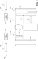
- FIG. 1 shows a schematic diagram of an illustrative apparatus for performing DMLM additive manufacturing.
- the apparatus may be referred to as a DMLM machine 100.
- the DMLM machine 100 builds objects, such as, for example, a part 122, in a layer-by-layer manner by sintering or melting a powder material using energy beams 136 and 137 generated by one or more sources such as, for example, laser 120 and 121. As explained above, a plurality of lasers may be used to build different sections of the part 122.
- the DMLM machine 100 includes two lasers 120, 121.
- the DMI,M machine 100 may include more than two lasers.
- the present disclosure relates primarily to in-situ field alignment for additive manufacturing using the DMLM machine 100, the various methods and processes described herein may also be implemented with another type of apparatus for additive manufacturing instead of the DMI,M machine 100.
- the powder to be melted by the energy beam is supplied by a reservoir 126 and is spread evenly over a build plate 114 using a recoater 116 (e.g., a recoater arm) traveling in a direction 134 to maintain the powder at a level 118 and/or remove excess powder material extending above the powder level 118 to waste container 128.
- the energy beams 136, 137 sinter or melt a cross sectional layer of the object being built under control of galvo scanners 132 and 133.
- the build plate 114 is then lowered and another layer of powder is spread over the part 122 being built, followed by successive melting/sintering of the powder by the lasers 120, 121. The process is repeated until the part 122 is completely built from the melted/sintered powder material.
- the top most layer of the part being built at any given time is referred to herein as a build plane.
- a layer of powder is spread over the current build plane of the part 122.
- the lasers 120, 121 may be controlled by a computer system including a processor and a memory.
- the computer system may determine a scan pattern for each layer and may control the lasers 120, 121 and the galvo scanners 132, 133 to irradiate the powder material according to the scan pattern.
- Each of the lasers 120, 121 may operate on a different portion of the build plate 114 and may be used to build different sections of the part 122.
- the laser 120 and the galvo scanner 132 may comprise a first laser channel 124, while the laser 121 and the galvo scanner 133 may comprise a second laser channel 125.
- the laser channels 124, 125 may also include mirrors, lenses, or other optical equipment to control the energy beams 136, 137.
- Post processing procedures may include removal of excess powder by, for example, blowing or vacuuming. Other post processing procedures may include a stress release process. Additionally, thermal and chemical post processing procedures may be used to finish the part 122.
- the laser channels are desirably calibrated with respect to each other. That is, the laser strikes from the lasers 120, 121 desirably occur at expected locations on the build plane of the part 122 such that the section of the part 122 built from the laser 120 and the section of the part 122 built from the laser 121 are properly aligned. If the calibration or alignment between the laser channels 124, 125 becomes disturbed, the sections of the part 122 built by the lasers 120 and 121 may not be properly aligned and materially defects may occur in the part 122.
- embodiments disclosed herein provide for in-situ field alignment of the DMLM machine 100.
- embodiments disclosed herein provide for alignment of the laser channels 124, 125 of the DMLM machine 100.
- embodiments disclosed herein may provide for the alignment of a DMLM machine having more than two laser channels.
- a camera may monitor the positions of the laser strikes made by the lasers 120, 121. By monitoring the positions of the laser strikes of the lasers 120, 121, the alignment of the laser channels 124, 125 with respect to each other may be determined, as disclosed herein. If the laser channels 124, 125 become misaligned, they may be adjusted to ensure proper alignment. In the example of FIG. 1 , a camera may be positioned to capture images along a line of sight of one of the lasers 120, 121, as disclosed herein.
- FIG. 2 shows a schematic diagram of a system 200 for performing in-situ field alignment of for DMI,M additive manufacturing, as disclosed herein.
- the system 200 includes the DMI,M machine 100 of FIG. 1 and an alignment apparatus 300, which is discussed in further detail below with respect to FIG. 3 .
- the system 200 further includes a camera 202, a photo diode 204, and a beam splitter 206.
- the camera 202 and the photo diode 204 may each contain multiple lens and other optical components.
- the DMLM machine 100 also includes a laser deflection mirror 208, a focusing lens 210, and reflecting mirrors 212 and 214 within the galvo scanner 133.
- the laser 121 is positioned such that the energy beam 137 emitted by the laser 121 is deflected by the laser deflection mirror 208 through the focusing lens 210, which is then directed towards the DMLM machine 100.
- the energy beam 136 may also be emitted by the laser 120, as shown in FIG. 1 .
- the part 122 in the example of FIG. 1 , may be built using the lasers 120, 121, as discussed above.
- the camera 202 is positioned to capture images along the optical line of sight 205 of the laser 121.
- the energy beam 137 emitted by the laser 121 may cause light to reflect and/or scatter off of the build plane of the part 122 and be directed by the galvo scanner 133 through the focusing lens 210 towards the laser deflection mirror 208.
- the light may then pass through laser deflection mirror 208 and be split by the beam splitter 206 such that a portion of the light travels to the camera 202 and a portion of the light travels to the photo diode 204.
- the camera 202 may then capture an image of the build plane of the part 122 along the line of sight 205 of the laser 121.
- one of the camera 202 or the photo diode 204 may not be included in the system 200.
- the system 200 may include other arrangements of the camera 202, the photo diode 204, and/or the laser 121 such that the camera 202 is able to capture images along the line of sight 205 of the laser 121.
- the system 200 may determine the position where the energy beam 137 emitted by the laser 121 strikes the build plane. This position may be compared to a position where the energy beam 137 was expected to strike the build plane. Furthermore, if a sequence of images along the field of view of the laser 121 also includes a laser strike of the energy beam 136 emitted by the laser 120, the system 200 may compare the position where the energy beam 136 strikes the build plane compared to where it was expected to strike.
- the relative position between the locations where the energy beams 136 and 137 strike the build plane may be compared to the relative position between the locations where the energy beams 136 and 137 were expected to strike the build plane. If the relative strike positions of the energy beams 136, 137 are within a threshold tolerance of the expected relative strike positions, the system 200 may determine that the laser channels 124, 125 are properly aligned with respect to each other. However, if the relative strike positions of the energy beams 136, 137 are outside of the threshold tolerance of the expected relative strike positions, the system 200 may determine that the laser channels 124, 125 are misaligned with respect to each other.
- the alignment apparatus 300 may receive images captured by the camera 202 and may determine whether the laser channels 124, 125 are misaligned with respect to each other, as disclosed herein.
- the components of the alignment apparatus 300 are schematically depicted.
- the alignment apparatus 300 may be part of a DMLM machine, such as the DMLM machine 100 of FIG. 1 .
- the alignment apparatus 300 may be a stand-alone computing device or may be part of a computing device separate from the DMLM machine 100.
- the alignment apparatus 300 may be within a system that includes the DMLM machine 100, such as the system 200 of FIG. 2 .
- the alignment apparatus 300 may include a processor 305, input/output hardware 310, network interface hardware 320, a data storage component 330, and a non-transitory memory component 340.
- the memory component 340 may be configured as volatile and/or nonvolatile computer readable medium and, as such, may include random access memory (including SRAM, DRAM, and/or other types of random access memory), flash memory, registers, compact discs (CD), digital versatile discs (DVD), and/or other types of storage components.
- the memory component 340 may be configured to store operating logic 342, a build data reception module 344, a fiducial strike determination module 346, an image data reception module 348, an alignment determination module 350, and an alignment correction module 352 (each of which may be embodied as a computer program, firmware, or hardware, as an example).
- a network interface 370 is also included in FIG. 3 and may be implemented as a bus or other interface to facilitate communication among the components of the alignment apparatus 300.
- the processor 305 may include any processing component configured to receive and execute instructions (such as from the data storage component 330 and/or the memory component 340).
- the input/output hardware 310 may include a monitor, keyboard, mouse, printer, camera, microphone, speaker, touch-screen, and/or other device for receiving input and outputting information.
- the network interface hardware 320 may include any wired or wireless networking hardware, such as a modem, LAN port, wireless fidelity (Wi-Fi) card, WiMax card, mobile communications hardware, and/or other hardware for communicating with other networks and/or devices, such as the DMI,M machine 100 of FIG. 1 .
- the data storage component 330 may store data received by the build data reception module 344 and/or the image data reception module 348.
- the data storage component 330 may also store other data utilized by the alignment apparatus 300, as described herein.
- the operating logic 342 may include an operating system and/or other software for managing components of the alignment apparatus 300.
- the build data reception module 344 may receive build data associated with a part to be built by the DMLM machine 100 (e.g., the part 122 of FIG. 1 ).
- the data received by the build data reception module 344 may indicate the shape of the part to be built by the DMI,M machine 100.
- the build data reception module 344 may receive data produced by CAD software.
- the build data reception module 344 may receive build data from other types of software programs (e.g., slice files).
- the data received by the build data reception module 344 may indicate which portions of the part 122 are to be built by each of the lasers 120, 121.
- the fiducial strike determination module 346 may determine fiducial strikes caused by the lasers 120, 121 during the build of the part 122.
- a fiducial strike is a laser strike made by a DMLM machine that is used to determine a relative alignment between multiple lasers of the DMI,M machine.
- the fiducial strike determination module 346 may determine fiducial strikes that are to be used to determine whether the laser channels 124, 125 are in alignment with each other.
- the system 200 may determine whether the lasers 120, 121 are properly aligned with respect to each other. This may be accomplished by analyzing a series of images captured by the camera 202 that includes laser strikes made by both the laser 120 and the laser 121.
- the fiducial strike determination module 346 may determine fiducial strikes to be used to calibrate the alignment of the laser channels 124, 125.
- the fiducial strikes may be made on the part 122 after a layer is complete before the next recoat. In other examples, the fiducial strikes may be made on powder after a recoat, before or after the next layer is built.
- one or more fiducial parts may be built across the build plane of the part 122 and the fiducial strikes may be made on the fiducial parts.
- multiple fiducial strikes may be made at a plurality of locations across the build plane and images showing the multiple fiducial strikes may be analyzed to determine the alignment of the laser channels 124, 125.
- the system 200 may determine an alignment of the laser channels 124, 125 at multiple layers of the part 122 while the part 122 is being built. In some examples, the system 200 may determine an alignment of the laser channels 124, 125 at every layer of the part 122 being built. In other examples, the system 200 may determine an alignment of the laser channels 124, 125 at a subset of the layers of the part 122. For example, the system may determine an alignment of the laser channels 124, 125 every n layers (e.g., every 2 layers, every 5 layers, every 10 layers, or the like). As such, the alignment of the laser channels 124, 125 may be continually checked while the part is being built.
- the fiducial strike determination module 346 may determine fiducial strikes at each layer of the part 122 at which the alignment of the laser channels 124, 125 is to be checked.
- the layers of the build of the part 122 at which the alignment of the laser channels 124, 125 is be determined may be specified by a user or may be specified in a configuration.
- the system 200 may monitor the alignment of the laser channels 124, 125 at multiple layers of the part 122 to determine if the alignment is changing over time.
- the fiducial strike determination module 346 may determine fiducial strikes based on laser strikes included in the build data reception module 344. That is, the fiducial strike determination module 346 may calibrate the laser channels 124, 125 based on laser strikes that are to be used as part of the build of the part 122. In contrast, in a second mode of operation, the fiducial strike determination module 346 may determine additional laser strikes to add to the build data specifically to be used for calibration of the laser channels 124, 125. That is, the fiducial strike determination module 346 may add laser strikes that are not needed to build the part 122, but are used to determine alignment of the laser channels 124, 125.
- the fiducial strike determination module 346 may analyze the build data received by the build data reception module 344 to determine appropriate laser strikes to use as fiducials.
- the fiducial strike determination module 346 may select laser strikes from both of the lasers 120, 121 that are within the field of view of the camera 202 as fiducials, such that the relative position of the laser strikes can be compared against each other.
- the fiducial strike determination module 346 may select laser strikes to be used as fiducials at each layer of the build of the part 122 at which the alignment of the laser channels 124, 125 is to be calibrated.
- the fiducial strike determination module 346 may determine fiducial strikes that are not used to build the part 122.
- the fiducial strike determination module 346 may generate locations for each of the lasers 120, 121 to strike that may be used as fiducials.
- the fiducial strike determination module 346 may generate fiducial strikes for the lasers 120, 121 that are within the field of view of the camera 202 such that the alignment of the laser channels 124, 125 may be determined.
- the fiducial strike determination module 346 may generate fiducial strikes at each layer of the part 122 for which alignment of the laser channels 124, 125 is to be determined.
- the fiducial strike determination module 346 may add the fiducial strike locations into the build file and may cause the network interface hardware 320 to transmit the modified build file with the fiducial strike locations to the DMLM machine 100 such that the DMLM machine may cause the lasers 120, 121 to make the fiducial strikes.
- the alignment apparatus 300 may analyze the fiducial strikes to determine whether the laser channels 124, 125 are properly aligned, as disclosed herein.
- the fiducial strike determination module 346 may determine fiducial strike locations that are located on the part 122 being built. However, the fiducial strikes are typically small enough so as not to degrade the structure of the part 122. In some examples, the fiducial strikes may be located on a portion of the build plane that does not include the part 122. For example, FIG. 4 shows a layer of the part 122 having fiducial strike locations 400, 402, 404, 406 located at positions on the build plane that do not include the part. Accordingly, fiducial strikes can be made at locations 400, 402, 404, 406 without affecting the part 122 at all. In other examples, the fiducial strikes may be made at a lower layer of the part 122.
- FIG. 5 shows an example layer of the part 122 that is to be discarded.
- fiducial strikes may be made at locations 500, 502, 504, 506, 508, 510, 512, 514, 516, 518, 520, 522, 524, 526, 528, 530, 532, 534, 536, 538, 540, 542, 544, 546, and 548 on the build plane without affecting the part 122, since this layer will be discarded from the final build of the part 122.
- the laser 120 and the laser 121 may not be time synchronized with each other. That is, the lasers 120, 121 may each build their respective portions of the part 122 with a timing that is not related to the timing of the other laser. During a normal build of the part 122, this may not cause any problems since the two portions of the part may be built independently and then stitched together. However, this lack of time synchronization may make it difficult to determine alignment of the laser channels 124, 125 if the fiducial strikes from the two lasers 120, 121 do not occur at the same time.
- the fiducial strike determination module 346 may determine multiple fiducial strikes for one or both of the lasers 120, 121.
- the camera 202 may then capture multiple images of each of the fiducial strikes and may stack the images together to determine the alignment of the laser channels 124, 125, as disclosed herein.
- the multiple fiducial strikes may comprise parallel lines used for hashing or rasterizing.
- FIG. 6 shows a stacked image 600 comprising a first parallel line comprising a plurality of laser strikes 602 from the laser 120 and a second parallel line comprising a plurality of laser strikes 604 from the laser 120.
- a laser strike 606 from the laser 121 may then be made halfway in between the parallel lines from the laser strikes 602 and 604. If the laser channels 124, 125 are properly aligned, the laser strike 606 will be positioned at the midpoint between the laser strikes 602 and 604 in the stacked image 500.
- the laser strike 606 may be offset from the midpoint between the laser strikes 602 and 604.
- the laser strike 606 is positioned 106.477 pixels from the laser strikes 602 but 105.712 pixels from the laser strikes 604, which corresponds to a misalignment of 276.4 microns.
- the image data reception module 348 may receive image data captured by the camera 202 and/or the photo diode 204 of the system 200 of FIG. 2 .
- the image data received by the image data reception module 348 may comprise images of laser strikes from the lasers 120, 121.
- the image data sequence received by the image data reception module 348 may show fiducial strikes made by the lasers 120, 121, and a stacked image may be generated from the image sequence such as the stacked image 600 of FIG. 6 .
- the alignment determination module 350 may analyze one or more received images to determine alignment of the laser channels 124, 125, as disclosed below.
- the alignment determination module 350 may analyze one or more images of fiducial strikes received by the image data reception module 348 to determine an alignment of the laser channels 124, 125, as disclosed herein.
- the alignment determination module 350 may compare the relative positions between the fiducial strikes made by the laser channels 124, 125 and the expected relative positions of the fiducial strikes as determined by the fiducial strike determination module 346. That is, the alignment determination module 350 may first determine the relative positions between fiducial strikes made by the laser channels 124 and 125. The alignment determination module 350 may then determine the expected relative positions between the fiducial strikes based on the output of the fiducial strike determination module 346. The alignment determination module 350 may then compare the actual relative positions to the expected relative positions.
- the alignment determination module 350 may compare one or more distances between fiducial strikes made by the laser channels 124, 125 and the expected distances between the fiducial strikes, such as in the example of FIG. 6 . For example, the alignment determination module 350 may compare the actual distance between the laser strikes 602 and the laser strike 606 to the expected distance between the laser strikes 602 and the laser strike 606. If the expected distances between the fiducial strikes made by the two lasers 120, 121 varies from the actual distances between the laser strikes, the alignment determination module 350 may determine that the laser channels 124, 125 are not properly aligned.
- the alignment determination module 350 may analyze a received image to determine a distance in pixels between two fiducial strikes made by the laser 120. This distance in pixels between the two fiducial strikes can be compared against a known nominal distance between the two fiducial strikes (e.g., based on the build data for the part 122) to determine a ratio of pixels per micron (or some other unit distance) for the received image. The alignment determination module 350 may further analyze the received image to determine a difference in pixels between the expected location and the actual location of a fiducial strike made by the laser 121 with respect to the fiducial strikes made by the laser 120. The alignment determination module 350 may then use the determine ratio of pixels per micron for the received image to determine a value of the relative error in alignment between the laser channels 124, 125.
- the alignment determination module 350 may determine an alignment between the laser channels 124, 125 for a single layer of the build of the part 122 at one or more locations across the build plane. In other examples, the alignment determination module 350 may determine an alignment between the laser channels 124, 125 for multiple layers of the build of the part 122 at one or more locations across the build plane. In some examples, the alignment determination module 350 may determine whether any change occurs in the alignment of the laser channels 124, 125 across multiple layers of the build of the part 122.
- the alignment correction module 352 may take certain action in response to a misalignment of the laser channels 124, 125 identified by the alignment determination module 350.
- the alignment correction module 352 may output a warning to an operator of the system 200 indicating that the laser channels 124, 125 are misaligned.
- the warning may include the amount of relative error in alignment between the laser channels 124, 125 determined by the alignment determination module 350.
- the alignment correction module 352 may take certain remedial action to correct the misalignment of the laser channels 124, 125, as described below.
- the alignment correction module 352 may perform a software correction to realign the laser channels 124, 125.
- the alignment correction module 352 may cause the DMLM machine 100 to modify the position of future laser strikes of one of the lasers 120 or 121 based on the amount of misalignment determined by the alignment determination module 350. This may allow the DMLM machine 100 to adjust future laser strikes to compensate for the misalignment between the laser channels 124, 125.
- the alignment correction module 352 may adjust the build plate 114 up or down by an amount based on the relative misalignment of the laser channels 124, 125 determined by the alignment determination module 350. This may cause the lasers 120, 121 to be moved away from each other to compensate for the misalignment of the laser channels 124, 125.
- the alignment correction module 352 may take remedial action as whenever the alignment determination module 350 determines a misalignment between the laser channels 124, 125 in an amount greater than a predetermined threshold. In other examples, the alignment correction module 352 may only take remedial action to correct a misalignment between the laser channels 124, 125 when the alignment correction module 352 detects a misalignment over multiple layers. This may prevent unnecessary correction due to a measurement or other error that may cause an inaccurate misalignment determination to be made at a single layer of the part 122.
- the build data reception module 344 receives a build file containing build data associated with the part 122.
- the build data may indicate laser strikes to be made by the lasers 120 and 121 of the DMLM machine 100.
- the fiducial strike determination module 346 determines fiducial strikes for the lasers 120, 121 based on the build data received by the build data reception module 344.
- the fiducial strike determination module 346 may select laser strikes that are part of the build data as fiducial strikes.
- the fiducial strike determination module 346 may modify the build file to add additional fiducial strikes to be made by the lasers 120 and 121. The fiducial strike determination module 346 may then transmit the modified build file back to the DMLM machine 100.
- the image data reception module 348 receives image data of the part while the part 122 is being built.
- the image data may be captured by the camera 202.
- the image data may comprise an image of reflected and/or scattered light from the build plane of the part 122 down-beam from the laser 121 such that the field of view of the image includes the laser strikes made by the laser 121.
- the image data of the part may indicate positions of a first set fiducial strikes made by the laser 120 and positions of a second set of fiducial strikes made by the laser 121.
- the alignment determination module 350 determines relative positions of the fiducial strikes made by the laser 120 and the laser 121 based on the image received by the image data reception module 348. In some examples, the alignment determination module 350 may determine a pixel distance between fiducial strikes and may then determine a nominal distance between the fiducial strikes based on the pixel distance.
- the alignment determination module 350 compares the determined relative positions of the fiducial strikes made by the lasers 120 and 121 to the expected relative positions of the fiducial strikes made by the lasers 120 and 121.
- the alignment determination module 350 determines whether the laser channels 124, 125 are properly aligned with respect to each other based on the comparison between the relative positions of the fiducial strikes and the expected positions of the fiducial strikes. If the alignment determination module 350 determines that the laser channels 124, 125 are properly aligned (YES at step 710), then control passes to step 714. If the alignment determination module 350 determines that the laser channels 124, 125 are not properly aligned (NO at step 710), then control passes to step 712.
- the alignment correction module 352 takes remedial action.
- the alignment correction module 352 issues a warning to notify an operator of the DMLM machine 100 that the laser channels 124, 125 are misaligned.
- the alignment correction module 352 may take remedial action to correct the misalignment of the laser channels 124, 125, as discussed above. Control then passes to step 714.
- the alignment apparatus 300 determines whether images of additional layers are to be received. If images of additional layers are to be received (YES at step 714), then control passes back to step 704 and the image data reception module 348 receives image data for the next layer for which alignment of the laser channels 124, 125 is to be checked. Alternatively, if no additional image data is to be received from additional layers (NO at step 714), then the method of FIG. 7 ends.
- build data associated with a part to be built by additive manufacturing may be received by an alignment apparatus, and the alignment apparatus may determine fiducial strikes based on the build data.
- the fiducial strikes may be laser strikes caused by lasers of a DMLM machine as part of the build data.
- the build file may be modified to include new laser strikes to be used as fiducial strikes.
- a camera with a field of view in line with one of the lasers may capture images of laser strikes being made on the build plane by more than one laser channel and the images may be transmitted to the alignment apparatus.
- the alignment apparatus may determine the positions of the fiducial strikes based on the images and may compare these positions to the expected positions of the fiducial strikes. Based on this comparison, the alignment apparatus may determine whether the laser channels are properly aligned with respect to each other. If the laser channels are not properly aligned, remedial action may be taken to notify an operator and/or correct the alignment.
- the techniques described above may still be used to determine an alignment of the laser channels.
- the camera 202 may capture images showing laser strikes from lasers of each of the laser channels, so long as the laser strikes are all within the field of view of the camera 202.
- other cameras may capture images showing laser strikes from one or more of the multiple laser channels that may be used to determine an alignment of the laser channels.
- An apparatus comprising one or more processors; one or more memory modules; and machine-readable instructions stored in the one or more memory modules that, when executed by the one or more processors, cause the apparatus to receive image data of one or more laser strikes on a build plane, the image data indicating positions of a first set of fiducial strikes made by a first laser on the build plane and positions of a second set of fiducial strikes made by a second laser on the build plane; determine relative positions of the first set of fiducial strikes and the second set of fiducial strikes with respect to each other from the received image data; compare the determined relative positions of the first and second sets of fiducial strikes with respect to each other to expected relative positions of the first and second sets of fiducial strikes with respect to each other; and determine whether the first laser and the second laser are misaligned with respect to each other based on the comparison.
- the image data comprises a plurality of images comprising the first set of fiducial strikes and the second set of fiducial strikes made at a plurality of time steps.
- first set of fiducial strikes comprises two parallel lines and the second set of fiducial strikes comprises one or more fiducial strikes between the two parallel lines.
- the instructions further cause the apparatus to receive a build file associated with the part indicating a first plurality of laser strikes to be made by the first laser and a second plurality of laser strikes to be made by the second laser; and determine the first set of fiducial strikes from among the first plurality of laser strikes and determine the second set of fiducial strikes from among the second plurality of laser strikes based on the build file.
- first set of fiducial strikes and the second set of fiducial strikes are within a field of view of a camera having a line of sight along a propagation direction of the first laser or the second laser.
- the camera has a line of sight along a propagation direction of the first laser or the second laser.
- instructions further cause the apparatus to determine laser strikes that are not included in the build file as the first set of fiducial strikes and the second set of fiducial strikes; and modify the build file to include the first set of fiducial strikes and the second set of fiducial strikes.
- the instructions further cause the apparatus to determine locations of the first set of fiducial strikes and the second set of fiducial strikes on a layer of the build file that will not be included in a final version of the part.
- the instructions further cause the apparatus to take remedial action to correct an alignment of the first laser of the second laser upon determination that the first laser and the second laser are misaligned with respect to each other.
- the instructions further cause the apparatus to receive second image data of the build plane while a part is being built on the build plane, the second image data being captured at a second location on the build plane, the second location is different than a location where the image data was captured, the second image data indicating positions of a third set of fiducial strikes made by the first laser on the build plane and positions of a fourth set of fiducial strikes made by the second laser on the build plane; determine relative positions of the third set of fiducial strikes and the fourth set of fiducial strikes from the received second image data; compare the determined relative positions of the third and fourth sets of fiducial strikes to expected relative positions; and determine whether the first laser and the second laser are misaligned with respect to each other at the second location based on the comparison.
- a method comprising receiving image data of one or more laser strikes on a build plane, the image data indicating positions of a first set of fiducial strikes made by a first laser on the build plane and positions of a second set of fiducial strikes made by a second laser on the build plane; determining relative positions of the first set of fiducial strikes and the second set of fiducial strikes with respect to each other from the received image data; comparing the determined relative positions of the first and second sets of fiducial strikes with respect to each other to expected relative positions of the first and second sets of fiducial strikes with respect to each other; and determining whether the first laser and the second laser are misaligned with respect to each other based on the comparing.
- the image data comprises a plurality of images comprising the first set of fiducial strikes and the second set of fiducial strikes made at a plurality of time steps.
- first set of fiducial strikes comprises two parallel lines and the second set of fiducial strikes comprises one or more fiducial strikes between the two parallel lines.
- any preceding clause further comprising receiving a build file associated with the part indicating a first plurality of laser strikes to be made by the first laser and a second plurality of laser strikes to be made by the second laser; and determining the first set of fiducial strikes from among the first plurality of laser strikes and determining the second set of fiducial strikes from among the second plurality of laser strikes based on the build file.
- any preceding clause further comprising receiving second image data of the build plane while a part is being built on the build plane, the second image data being captured at a second location on the build plane, the second location is different than a location where the image data was captured, the second image data indicating positions of a third set of fiducial strikes made by the first laser on the build plane and positions of a fourth set of fiducial strikes made by the second laser on the build plane; determining relative positions of the third set of fiducial strikes and the fourth set of fiducial strikes from the received second image data; comparing the determined relative positions of the third and fourth sets of fiducial strikes to expected relative positions; and determining whether the first laser and the second laser are misaligned with respect to each other at the second location based on the comparing.
- a system comprising an apparatus for building a part by additive manufacturing using at least a first laser and a second laser, the apparatus comprising a build plane on which the part is built; a camera having a line of sight along a propagation direction of the first laser or the second laser; and an alignment apparatus configured to receive image data of one or more laser strikes on the build plane, the image data is captured by the camera indicating positions of a first set of fiducial strikes made by the first laser on the build plane and positions of a second set of fiducial strikes made by the second laser on the build plane; determine relative positions of the first set of fiducial strikes and the second set of fiducial strikes with respect to each other based on the received image data; compare the determined relative positions of the first and second sets of fiducial strikes with respect to each other to expected relative positions of the first and second sets of fiducial strikes with respect to each othwer; and determine whether the first laser and the second laser are misaligned with respect to each other based on the comparison.
- the image data comprises a plurality of images comprising the first set of fiducial strikes and the second set of fiducial strikes made at a plurality of time steps.
- first set of fiducial strikes comprises two parallel lines and the second set of fiducial strikes comprises one or more fiducial strikes between the two parallel lines.
- the alignment apparatus is further configured to receive a build file associated with the part indicating a first plurality of laser strikes to be made by the first laser and a second plurality of laser strikes to be made by the second laser; and determine the first set of fiducial strikes from among the first plurality of laser strikes and determine the second set of fiducial strikes from among the second plurality of laser strikes based on the build file.
- the alignment apparatus is further configured to determine fiducial strikes at multiple layers of the part.
- the alignment apparatus is further configured to determine laser strikes that are not included in the build file as the first set of fiducial strikes and the second set of fiducial strikes; and modify the build file to include the first set of fiducial strikes and the second set of fiducial strikes.
- the alignment apparatus is further configured to determine locations of the first set of fiducial strikes and the second set of fiducial strikes on a layer of the build file that will not be included in a final version of the part.
- the alignment apparatus is further configured to determine locations of the first set of fiducial strikes and the second set of fiducial strikes at a location outside of the part.
- the alignment apparatus is further configured to output a warning upon determination that the first laser and the second laser are misaligned with respect to each other.
- the alignment apparatus is further configured to take remedial action to correct an alignment of the first laser of the second laser upon determination that the first laser and the second laser are misaligned with respect to each other.
- the alignment apparatus is further configured to receive second image data of the build plane while a part is being built on the build plane, the second image data being captured at a second location on the build plane, the second location is different than a location where the image data was captured, the second image data indicating positions of a third set of fiducial strikes made by the first laser on the build plane and positions of a fourth set of fiducial strikes made by the second laser on the build plane; determine relative positions of the third set of fiducial strikes and the fourth set of fiducial strikes from the received second image data; compare the determined relative positions of the third and fourth sets of fiducial strikes to expected relative positions; and determine whether the first laser and the second laser are misaligned with respect to each other at the second location based on the comparison.
Landscapes
- Engineering & Computer Science (AREA)
- Chemical & Material Sciences (AREA)
- Materials Engineering (AREA)
- Manufacturing & Machinery (AREA)
- Health & Medical Sciences (AREA)
- General Health & Medical Sciences (AREA)
- Toxicology (AREA)
- Physics & Mathematics (AREA)
- Automation & Control Theory (AREA)
- Analytical Chemistry (AREA)
- Plasma & Fusion (AREA)
- Computer Vision & Pattern Recognition (AREA)
- General Physics & Mathematics (AREA)
- Theoretical Computer Science (AREA)
- Quality & Reliability (AREA)
- Optics & Photonics (AREA)
- Laser Beam Processing (AREA)
Abstract
Description
- The present disclosure relates to additive manufacturing, and more specifically, to in-situ field alignment detection for additive manufacturing.
- Direct metal laser melting (DMI,M) is an additive manufacturing process that uses lasers to melt ultra-thin layers of metal powder to build a three-dimensional object or part. During operation of a DMLM machine including a plurality of lasers, one or more of the lasers may become misaligned with respect to one or more of the other lasers. If this happens, a seam or other material defect may be introduced into the part being built.
-
-
FIG. 1 schematically depicts an example additive manufacturing machine for building a part by additive manufacturing, according to one or more embodiments shown and described herein; -
FIG. 2 schematically depicts a system for performing in-situ field alignment for additive manufacturing, according to one or more embodiments shown and described herein; -
FIG. 3 schematically depicts an alignment apparatus, according to one or more embodiments shown and described herein; -
FIG. 4 depicts an example cross section of a layer of a part that may be built by the additive manufacturing machine ofFIG. 1 , according to one or more embodiments shown and described herein; -
FIG. 5 depicts another example cross section of a layer of a part that may be built by the additive manufacturing machine ofFIG. 1 , according to one or more embodiments shown and described herein; -
FIG. 6 depicts an image that may be used by the system ofFIG. 2 to perform in-situ field alignment, according to one or more embodiments shown and described herein; and -
FIG. 7 depicts a flow diagram of an illustrative method for performing in-situ field alignment for additive manufacturing, according to one or more embodiments shown and described herein. - The present disclosure generally relates to in-situ field alignment for additive manufacturing. In the illustrated example, the present disclosure relates to direct metal laser melting (DMLM). However, in other examples, the present disclosure may be utilized with other types of additive manufacturing
- Direct metal laser melting (DMI,M) is an additive manufacturing process that uses lasers to melt ultra-thin layers of metal powder to build a three-dimensional object or part. During operation of a DMLM machine including a plurality of lasers, one or more of the lasers may become misaligned with respect to one or more of the other lasers. If this happens, a seam or other material defect may be introduced into the part being built
- Computer-aided design (CAD) software may be used to design a three-dimensional part. An output file generated by the CAD software may then be converted into a plurality of slice files representing different layers of the part. The slice files are then loaded onto a DMLM machine for building the part.
- During operation, a recoater moves across a build platform and evenly spreads a thin layer of fine metal powder. A laser then melts the powder to form a cross-section of the part for one layer based on a slice file. The build platform is then lowered and the process is repeated for the next layer of the part. In some examples, a DMLM machine may include a plurality of lasers. Each laser may operate over a different portion of the build platform. As such, a part to be built may be stitched together from multiple sections, with each laser being used to build a different section. This may allow for larger parts to be built than may be possible using a single laser and/or allow for a quicker formation of parts relative to a single laser process.
- However, if the plurality of lasers of the DMI,M machine are misaligned with respect to each other, the part may not be properly stitched together. Accordingly, in embodiments disclosed herein, a camera may be positioned to capture images along a line of sight of one of the lasers. As such, the camera may capture images of laser strikes made by the laser on the build platform of the DMLM machine. If the camera is able to also capture an image of one or more laser strikes made by another laser of the DMLM machine within the same frame, the expected relative position between the laser strikes of the two lasers may be compared to the actual relative position between the laser strikes of the two lasers. If the relative position between the strikes from the two lasers is not as expected, it may be determined that the lasers are misaligned with respect to each other, and corrective action may be taken to properly align the lasers.
-
FIG. 1 shows a schematic diagram of an illustrative apparatus for performing DMLM additive manufacturing. As used herein, the apparatus may be referred to as aDMLM machine 100. TheDMLM machine 100 builds objects, such as, for example, apart 122, in a layer-by-layer manner by sintering or melting a powder material usingenergy beams laser part 122. In the example ofFIG. 1 , theDMLM machine 100 includes twolasers M machine 100 may include more than two lasers. In addition, while the present disclosure relates primarily to in-situ field alignment for additive manufacturing using theDMLM machine 100, the various methods and processes described herein may also be implemented with another type of apparatus for additive manufacturing instead of the DMI,M machine 100. - The powder to be melted by the energy beam is supplied by a
reservoir 126 and is spread evenly over abuild plate 114 using a recoater 116 (e.g., a recoater arm) traveling in adirection 134 to maintain the powder at alevel 118 and/or remove excess powder material extending above thepowder level 118 towaste container 128. Theenergy beams galvo scanners build plate 114 is then lowered and another layer of powder is spread over thepart 122 being built, followed by successive melting/sintering of the powder by thelasers part 122 is completely built from the melted/sintered powder material. - As each layer of the
part 122 is being built by theDMLM machine 100, the top most layer of the part being built at any given time is referred to herein as a build plane. As such, as each successive layer of thepart 122 is being built, a layer of powder is spread over the current build plane of thepart 122. - The
lasers lasers galvo scanners lasers build plate 114 and may be used to build different sections of thepart 122. In embodiments, thelaser 120 and thegalvo scanner 132 may comprise afirst laser channel 124, while thelaser 121 and thegalvo scanner 133 may comprise asecond laser channel 125. Thelaser channels energy beams - After fabrication of the
part 122 is complete, various post-processing procedures may be applied to thepart 122. Post processing procedures may include removal of excess powder by, for example, blowing or vacuuming. Other post processing procedures may include a stress release process. Additionally, thermal and chemical post processing procedures may be used to finish thepart 122. - In order for the
part 122 to be built in multiple sections using thelasers lasers part 122 such that the section of thepart 122 built from thelaser 120 and the section of thepart 122 built from thelaser 121 are properly aligned. If the calibration or alignment between thelaser channels part 122 built by thelasers part 122. - Accordingly, embodiments disclosed herein provide for in-situ field alignment of the
DMLM machine 100. In particular, embodiments disclosed herein provide for alignment of thelaser channels DMLM machine 100. However, in other examples, embodiments disclosed herein may provide for the alignment of a DMLM machine having more than two laser channels. - In embodiments disclosed herein, a camera may monitor the positions of the laser strikes made by the
lasers lasers laser channels laser channels FIG. 1 , a camera may be positioned to capture images along a line of sight of one of thelasers -
FIG. 2 shows a schematic diagram of asystem 200 for performing in-situ field alignment of for DMI,M additive manufacturing, as disclosed herein. In the example ofFIG. 2 , thesystem 200 includes the DMI,M machine 100 ofFIG. 1 and analignment apparatus 300, which is discussed in further detail below with respect toFIG. 3 . Thesystem 200 further includes acamera 202, aphoto diode 204, and abeam splitter 206. Thecamera 202 and thephoto diode 204 may each contain multiple lens and other optical components. Furthermore, as shown inFIG. 2 , theDMLM machine 100 also includes alaser deflection mirror 208, a focusinglens 210, and reflectingmirrors galvo scanner 133. - In the example of
FIG. 2 , thelaser 121 is positioned such that theenergy beam 137 emitted by thelaser 121 is deflected by thelaser deflection mirror 208 through the focusinglens 210, which is then directed towards theDMLM machine 100. Theenergy beam 136 may also be emitted by thelaser 120, as shown inFIG. 1 . As such, thepart 122, in the example ofFIG. 1 , may be built using thelasers - Also in the example of
FIG. 2 , thecamera 202 is positioned to capture images along the optical line ofsight 205 of thelaser 121. In particular, theenergy beam 137 emitted by thelaser 121 may cause light to reflect and/or scatter off of the build plane of thepart 122 and be directed by thegalvo scanner 133 through the focusinglens 210 towards thelaser deflection mirror 208. The light may then pass throughlaser deflection mirror 208 and be split by thebeam splitter 206 such that a portion of the light travels to thecamera 202 and a portion of the light travels to thephoto diode 204. Thecamera 202 may then capture an image of the build plane of thepart 122 along the line ofsight 205 of thelaser 121. In some examples, one of thecamera 202 or thephoto diode 204 may not be included in thesystem 200. In some examples, thesystem 200 may include other arrangements of thecamera 202, thephoto diode 204, and/or thelaser 121 such that thecamera 202 is able to capture images along the line ofsight 205 of thelaser 121. - By capturing a sequence of images of reflected and/or scattered laser strikes from the build plane along the field of view of the
laser 121, thesystem 200 may determine the position where theenergy beam 137 emitted by thelaser 121 strikes the build plane. This position may be compared to a position where theenergy beam 137 was expected to strike the build plane. Furthermore, if a sequence of images along the field of view of thelaser 121 also includes a laser strike of theenergy beam 136 emitted by thelaser 120, thesystem 200 may compare the position where theenergy beam 136 strikes the build plane compared to where it was expected to strike. As such, the relative position between the locations where theenergy beams energy beams energy beams system 200 may determine that thelaser channels energy beams system 200 may determine that thelaser channels - Referring to
FIG. 3 , thealignment apparatus 300 may receive images captured by thecamera 202 and may determine whether thelaser channels alignment apparatus 300 are schematically depicted. In some examples, thealignment apparatus 300 may be part of a DMLM machine, such as theDMLM machine 100 ofFIG. 1 . In other examples, thealignment apparatus 300 may be a stand-alone computing device or may be part of a computing device separate from theDMLM machine 100. In other examples, thealignment apparatus 300 may be within a system that includes theDMLM machine 100, such as thesystem 200 ofFIG. 2 . - As illustrated in
FIG. 3 , thealignment apparatus 300 may include aprocessor 305, input/output hardware 310,network interface hardware 320, adata storage component 330, and anon-transitory memory component 340. Thememory component 340 may be configured as volatile and/or nonvolatile computer readable medium and, as such, may include random access memory (including SRAM, DRAM, and/or other types of random access memory), flash memory, registers, compact discs (CD), digital versatile discs (DVD), and/or other types of storage components. Additionally, thememory component 340 may be configured to storeoperating logic 342, a builddata reception module 344, a fiducialstrike determination module 346, an imagedata reception module 348, analignment determination module 350, and an alignment correction module 352 (each of which may be embodied as a computer program, firmware, or hardware, as an example). Anetwork interface 370 is also included inFIG. 3 and may be implemented as a bus or other interface to facilitate communication among the components of thealignment apparatus 300. - The
processor 305 may include any processing component configured to receive and execute instructions (such as from thedata storage component 330 and/or the memory component 340). The input/output hardware 310 may include a monitor, keyboard, mouse, printer, camera, microphone, speaker, touch-screen, and/or other device for receiving input and outputting information. Thenetwork interface hardware 320 may include any wired or wireless networking hardware, such as a modem, LAN port, wireless fidelity (Wi-Fi) card, WiMax card, mobile communications hardware, and/or other hardware for communicating with other networks and/or devices, such as the DMI,M machine 100 ofFIG. 1 . - Referring still to
FIG. 3 , thedata storage component 330 may store data received by the builddata reception module 344 and/or the imagedata reception module 348. Thedata storage component 330 may also store other data utilized by thealignment apparatus 300, as described herein. - Included in the
memory component 340 are the operatinglogic 342, the builddata reception module 344, the fiducialstrike determination module 346, the imagedata reception module 348, thealignment determination module 350, and thealignment correction module 352. The operatinglogic 342 may include an operating system and/or other software for managing components of thealignment apparatus 300. - The build
data reception module 344 may receive build data associated with a part to be built by the DMLM machine 100 (e.g., thepart 122 ofFIG. 1 ). The data received by the builddata reception module 344 may indicate the shape of the part to be built by the DMI,M machine 100. In some examples, the builddata reception module 344 may receive data produced by CAD software. However, in other examples, the builddata reception module 344 may receive build data from other types of software programs (e.g., slice files). In embodiments, the data received by the builddata reception module 344 may indicate which portions of thepart 122 are to be built by each of thelasers - The fiducial
strike determination module 346 may determine fiducial strikes caused by thelasers part 122. As used herein, a fiducial strike is a laser strike made by a DMLM machine that is used to determine a relative alignment between multiple lasers of the DMI,M machine. In particular, the fiducialstrike determination module 346 may determine fiducial strikes that are to be used to determine whether thelaser channels system 200 may determine whether thelasers camera 202 that includes laser strikes made by both thelaser 120 and thelaser 121. - When images captured by the
camera 202 includes positions of strikes made by bothlasers strike determination module 346 may determine fiducial strikes to be used to calibrate the alignment of thelaser channels part 122 after a layer is complete before the next recoat. In other examples, the fiducial strikes may be made on powder after a recoat, before or after the next layer is built. In some examples, one or more fiducial parts may be built across the build plane of thepart 122 and the fiducial strikes may be made on the fiducial parts. In some examples, multiple fiducial strikes may be made at a plurality of locations across the build plane and images showing the multiple fiducial strikes may be analyzed to determine the alignment of thelaser channels - In some examples, the
system 200 may determine an alignment of thelaser channels part 122 while thepart 122 is being built. In some examples, thesystem 200 may determine an alignment of thelaser channels part 122 being built. In other examples, thesystem 200 may determine an alignment of thelaser channels part 122. For example, the system may determine an alignment of thelaser channels laser channels strike determination module 346 may determine fiducial strikes at each layer of thepart 122 at which the alignment of thelaser channels part 122 at which the alignment of thelaser channels system 200 may monitor the alignment of thelaser channels part 122 to determine if the alignment is changing over time. - In a first mode of operation, the fiducial
strike determination module 346 may determine fiducial strikes based on laser strikes included in the builddata reception module 344. That is, the fiducialstrike determination module 346 may calibrate thelaser channels part 122. In contrast, in a second mode of operation, the fiducialstrike determination module 346 may determine additional laser strikes to add to the build data specifically to be used for calibration of thelaser channels strike determination module 346 may add laser strikes that are not needed to build thepart 122, but are used to determine alignment of thelaser channels - In the first mode of operation, the fiducial
strike determination module 346 may analyze the build data received by the builddata reception module 344 to determine appropriate laser strikes to use as fiducials. In particular, the fiducialstrike determination module 346 may select laser strikes from both of thelasers camera 202 as fiducials, such that the relative position of the laser strikes can be compared against each other. In examples for which the alignment of thelaser channels strike determination module 346 may select laser strikes to be used as fiducials at each layer of the build of thepart 122 at which the alignment of thelaser channels - In the second mode of operation, the fiducial
strike determination module 346 may determine fiducial strikes that are not used to build thepart 122. In particular, in some examples, the fiducialstrike determination module 346 may generate locations for each of thelasers strike determination module 346 may generate fiducial strikes for thelasers camera 202 such that the alignment of thelaser channels laser channels strike determination module 346 may generate fiducial strikes at each layer of thepart 122 for which alignment of thelaser channels lasers strike determination module 346 may add the fiducial strike locations into the build file and may cause thenetwork interface hardware 320 to transmit the modified build file with the fiducial strike locations to theDMLM machine 100 such that the DMLM machine may cause thelasers M machine 100 causes thelasers alignment apparatus 300 may analyze the fiducial strikes to determine whether thelaser channels - In some examples, in the second mode of operation, the fiducial
strike determination module 346 may determine fiducial strike locations that are located on thepart 122 being built. However, the fiducial strikes are typically small enough so as not to degrade the structure of thepart 122. In some examples, the fiducial strikes may be located on a portion of the build plane that does not include thepart 122. For example,FIG. 4 shows a layer of thepart 122 havingfiducial strike locations locations part 122 at all. In other examples, the fiducial strikes may be made at a lower layer of thepart 122. When building a part using DMLM manufacturing, the first few layers of the build are typically discarded. Accordingly, fiducial strikes may be made on a layer of thepart 122 to be discarded without affecting the structure of thepart 122. For example,FIG. 5 shows an example layer of thepart 122 that is to be discarded. In the example ofFIG. 5 , fiducial strikes may be made atlocations part 122, since this layer will be discarded from the final build of thepart 122. - In some examples, in either the first mode of operation or the second mode of operation, the
laser 120 and thelaser 121 may not be time synchronized with each other. That is, thelasers part 122 with a timing that is not related to the timing of the other laser. During a normal build of thepart 122, this may not cause any problems since the two portions of the part may be built independently and then stitched together. However, this lack of time synchronization may make it difficult to determine alignment of thelaser channels lasers strike determination module 346 may determine multiple fiducial strikes for one or both of thelasers camera 202 may then capture multiple images of each of the fiducial strikes and may stack the images together to determine the alignment of thelaser channels - In one example, the multiple fiducial strikes may comprise parallel lines used for hashing or rasterizing. For example,
FIG. 6 shows astacked image 600 comprising a first parallel line comprising a plurality oflaser strikes 602 from thelaser 120 and a second parallel line comprising a plurality oflaser strikes 604 from thelaser 120. Alaser strike 606 from thelaser 121 may then be made halfway in between the parallel lines from the laser strikes 602 and 604. If thelaser channels laser strike 606 will be positioned at the midpoint between the laser strikes 602 and 604 in thestacked image 500. However, if thelaser channels laser strike 606 may be offset from the midpoint between the laser strikes 602 and 604. In the example ofFIG. 6 , thelaser strike 606 is positioned 106.477 pixels from the laser strikes 602 but 105.712 pixels from the laser strikes 604, which corresponds to a misalignment of 276.4 microns. - Referring back to
FIG. 3 , the imagedata reception module 348 may receive image data captured by thecamera 202 and/or thephoto diode 204 of thesystem 200 ofFIG. 2 . The image data received by the imagedata reception module 348 may comprise images of laser strikes from thelasers data reception module 348 may show fiducial strikes made by thelasers stacked image 600 ofFIG. 6 . After the imagedata reception module 348 receives image data of fiducial strikes, thealignment determination module 350 may analyze one or more received images to determine alignment of thelaser channels - Referring still to
FIG. 3 , thealignment determination module 350 may analyze one or more images of fiducial strikes received by the imagedata reception module 348 to determine an alignment of thelaser channels alignment determination module 350 may compare the relative positions between the fiducial strikes made by thelaser channels strike determination module 346. That is, thealignment determination module 350 may first determine the relative positions between fiducial strikes made by thelaser channels alignment determination module 350 may then determine the expected relative positions between the fiducial strikes based on the output of the fiducialstrike determination module 346. Thealignment determination module 350 may then compare the actual relative positions to the expected relative positions. - In one example, the
alignment determination module 350 may compare one or more distances between fiducial strikes made by thelaser channels FIG. 6 . For example, thealignment determination module 350 may compare the actual distance between the laser strikes 602 and thelaser strike 606 to the expected distance between the laser strikes 602 and thelaser strike 606. If the expected distances between the fiducial strikes made by the twolasers alignment determination module 350 may determine that thelaser channels - In one example, the
alignment determination module 350 may analyze a received image to determine a distance in pixels between two fiducial strikes made by thelaser 120. This distance in pixels between the two fiducial strikes can be compared against a known nominal distance between the two fiducial strikes (e.g., based on the build data for the part 122) to determine a ratio of pixels per micron (or some other unit distance) for the received image. Thealignment determination module 350 may further analyze the received image to determine a difference in pixels between the expected location and the actual location of a fiducial strike made by thelaser 121 with respect to the fiducial strikes made by thelaser 120. Thealignment determination module 350 may then use the determine ratio of pixels per micron for the received image to determine a value of the relative error in alignment between thelaser channels - In some examples, the
alignment determination module 350 may determine an alignment between thelaser channels part 122 at one or more locations across the build plane. In other examples, thealignment determination module 350 may determine an alignment between thelaser channels part 122 at one or more locations across the build plane. In some examples, thealignment determination module 350 may determine whether any change occurs in the alignment of thelaser channels part 122. - Referring still to
FIG. 3 , thealignment correction module 352 may take certain action in response to a misalignment of thelaser channels alignment determination module 350. In some examples, thealignment correction module 352 may output a warning to an operator of thesystem 200 indicating that thelaser channels laser channels alignment determination module 350. In other examples, thealignment correction module 352 may take certain remedial action to correct the misalignment of thelaser channels - In some examples, the
alignment correction module 352 may perform a software correction to realign thelaser channels alignment correction module 352 may cause theDMLM machine 100 to modify the position of future laser strikes of one of thelasers alignment determination module 350. This may allow theDMLM machine 100 to adjust future laser strikes to compensate for the misalignment between thelaser channels - In some examples, the
alignment correction module 352 may adjust thebuild plate 114 up or down by an amount based on the relative misalignment of thelaser channels alignment determination module 350. This may cause thelasers laser channels - In some examples, the
alignment correction module 352 may take remedial action as whenever thealignment determination module 350 determines a misalignment between thelaser channels alignment correction module 352 may only take remedial action to correct a misalignment between thelaser channels alignment correction module 352 detects a misalignment over multiple layers. This may prevent unnecessary correction due to a measurement or other error that may cause an inaccurate misalignment determination to be made at a single layer of thepart 122. - Referring now to
FIG. 7 , a flow chart is shown of an example method of operating thealignment apparatus 300 ofFIGS. 2 and3 . Atstep 700, the builddata reception module 344 receives a build file containing build data associated with thepart 122. The build data may indicate laser strikes to be made by thelasers DMLM machine 100. - At
step 702, the fiducialstrike determination module 346 determines fiducial strikes for thelasers data reception module 344. In the first mode of operation, the fiducialstrike determination module 346 may select laser strikes that are part of the build data as fiducial strikes. In the second mode of operation, the fiducialstrike determination module 346 may modify the build file to add additional fiducial strikes to be made by thelasers strike determination module 346 may then transmit the modified build file back to theDMLM machine 100. - At
step 704, the imagedata reception module 348 receives image data of the part while thepart 122 is being built. The image data may be captured by thecamera 202. The image data may comprise an image of reflected and/or scattered light from the build plane of thepart 122 down-beam from thelaser 121 such that the field of view of the image includes the laser strikes made by thelaser 121. As such, the image data of the part may indicate positions of a first set fiducial strikes made by thelaser 120 and positions of a second set of fiducial strikes made by thelaser 121. - At
step 706, thealignment determination module 350 determines relative positions of the fiducial strikes made by thelaser 120 and thelaser 121 based on the image received by the imagedata reception module 348. In some examples, thealignment determination module 350 may determine a pixel distance between fiducial strikes and may then determine a nominal distance between the fiducial strikes based on the pixel distance. - At
step 708, thealignment determination module 350 compares the determined relative positions of the fiducial strikes made by thelasers lasers step 710, thealignment determination module 350 determines whether thelaser channels alignment determination module 350 determines that thelaser channels alignment determination module 350 determines that thelaser channels - At
step 712, thealignment correction module 352 takes remedial action. In some examples, thealignment correction module 352 issues a warning to notify an operator of theDMLM machine 100 that thelaser channels alignment correction module 352 may take remedial action to correct the misalignment of thelaser channels - At
step 714, thealignment apparatus 300 determines whether images of additional layers are to be received. If images of additional layers are to be received (YES at step 714), then control passes back to step 704 and the imagedata reception module 348 receives image data for the next layer for which alignment of thelaser channels FIG. 7 ends. - It should now be understood that devices, systems, and methods described herein provide in-situ field alignment for DMLM additive manufacturing using multiple lasers. In embodiments disclosed herein, build data associated with a part to be built by additive manufacturing may be received by an alignment apparatus, and the alignment apparatus may determine fiducial strikes based on the build data. In a first mode of operation, the fiducial strikes may be laser strikes caused by lasers of a DMLM machine as part of the build data. In a second mode of operation, the build file may be modified to include new laser strikes to be used as fiducial strikes.
- During the build of the part, a camera with a field of view in line with one of the lasers may capture images of laser strikes being made on the build plane by more than one laser channel and the images may be transmitted to the alignment apparatus. The alignment apparatus may determine the positions of the fiducial strikes based on the images and may compare these positions to the expected positions of the fiducial strikes. Based on this comparison, the alignment apparatus may determine whether the laser channels are properly aligned with respect to each other. If the laser channels are not properly aligned, remedial action may be taken to notify an operator and/or correct the alignment.
- In examples in which more than two laser channels are used to build the
part 122, the techniques described above may still be used to determine an alignment of the laser channels. In these examples, thecamera 202 may capture images showing laser strikes from lasers of each of the laser channels, so long as the laser strikes are all within the field of view of thecamera 202. In some examples, other cameras may capture images showing laser strikes from one or more of the multiple laser channels that may be used to determine an alignment of the laser channels. - Further aspects of the disclosure are provided by the subject matter of the following clauses.
- An apparatus comprising one or more processors; one or more memory modules; and machine-readable instructions stored in the one or more memory modules that, when executed by the one or more processors, cause the apparatus to receive image data of one or more laser strikes on a build plane, the image data indicating positions of a first set of fiducial strikes made by a first laser on the build plane and positions of a second set of fiducial strikes made by a second laser on the build plane; determine relative positions of the first set of fiducial strikes and the second set of fiducial strikes with respect to each other from the received image data; compare the determined relative positions of the first and second sets of fiducial strikes with respect to each other to expected relative positions of the first and second sets of fiducial strikes with respect to each other; and determine whether the first laser and the second laser are misaligned with respect to each other based on the comparison.
- The apparatus of any preceding clause, wherein the image data comprises a plurality of images comprising the first set of fiducial strikes and the second set of fiducial strikes made at a plurality of time steps.
- The apparatus of any preceding clause, wherein the first set of fiducial strikes comprises two parallel lines and the second set of fiducial strikes comprises one or more fiducial strikes between the two parallel lines.
- The apparatus of any preceding clause, wherein the instructions further cause the apparatus to receive a build file associated with the part indicating a first plurality of laser strikes to be made by the first laser and a second plurality of laser strikes to be made by the second laser; and determine the first set of fiducial strikes from among the first plurality of laser strikes and determine the second set of fiducial strikes from among the second plurality of laser strikes based on the build file.
- The apparatus of any preceding clause, wherein the instructions further cause the apparatus to determine fiducial strikes at multiple layers of the part.
- The apparatus of any preceding clause, wherein the first set of fiducial strikes and the second set of fiducial strikes are within a field of view of a camera having a line of sight along a propagation direction of the first laser or the second laser.
- The apparatus of any preceding clause, wherein the camera has a line of sight along a propagation direction of the first laser or the second laser.
- The apparatus of any preceding clause, wherein the instructions further cause the apparatus to determine laser strikes that are not included in the build file as the first set of fiducial strikes and the second set of fiducial strikes; and modify the build file to include the first set of fiducial strikes and the second set of fiducial strikes.
- The apparatus of any preceding clause, wherein the instructions further cause the apparatus to determine locations of the first set of fiducial strikes and the second set of fiducial strikes on a layer of the build file that will not be included in a final version of the part.
- The apparatus of any preceding clause, wherein the instructions further cause the apparatus to determine locations of the first set of fiducial strikes and the second set of fiducial strikes at a location outside of the part.
- The apparatus of any preceding clause, wherein the instructions further cause the apparatus to output a warning upon determination that the first laser and the second laser are misaligned with respect to each other.
- The apparatus of any preceding clause, wherein the instructions further cause the apparatus to take remedial action to correct an alignment of the first laser of the second laser upon determination that the first laser and the second laser are misaligned with respect to each other.
- The apparatus of any preceding clause, wherein the instructions further cause the apparatus to receive second image data of the build plane while a part is being built on the build plane, the second image data being captured at a second location on the build plane, the second location is different than a location where the image data was captured, the second image data indicating positions of a third set of fiducial strikes made by the first laser on the build plane and positions of a fourth set of fiducial strikes made by the second laser on the build plane; determine relative positions of the third set of fiducial strikes and the fourth set of fiducial strikes from the received second image data; compare the determined relative positions of the third and fourth sets of fiducial strikes to expected relative positions; and determine whether the first laser and the second laser are misaligned with respect to each other at the second location based on the comparison.
- A method, comprising receiving image data of one or more laser strikes on a build plane, the image data indicating positions of a first set of fiducial strikes made by a first laser on the build plane and positions of a second set of fiducial strikes made by a second laser on the build plane; determining relative positions of the first set of fiducial strikes and the second set of fiducial strikes with respect to each other from the received image data; comparing the determined relative positions of the first and second sets of fiducial strikes with respect to each other to expected relative positions of the first and second sets of fiducial strikes with respect to each other; and determining whether the first laser and the second laser are misaligned with respect to each other based on the comparing.
- The method of any preceding clause, wherein the image data comprises a plurality of images comprising the first set of fiducial strikes and the second set of fiducial strikes made at a plurality of time steps.
- The method of any preceding clause, wherein the first set of fiducial strikes comprises two parallel lines and the second set of fiducial strikes comprises one or more fiducial strikes between the two parallel lines.
- The method of any preceding clause, further comprising receiving a build file associated with the part indicating a first plurality of laser strikes to be made by the first laser and a second plurality of laser strikes to be made by the second laser; and determining the first set of fiducial strikes from among the first plurality of laser strikes and determining the second set of fiducial strikes from among the second plurality of laser strikes based on the build file.
- The method of any preceding clause, further comprising determining fiducial strikes at multiple layers of the part.
- The method of any preceding clause, wherein the first set of fiducial strikes and the second set of fiducial strikes are within a field of view of a camera associated with an additive manufacturing apparatus.
- The method of any preceding clause, wherein the camera has a line of sight along a propagation direction of the first laser or the second laser.
- The method of any preceding clause, further comprising determining laser strikes that are not included in the build file as the first set of fiducial strikes and the second set of fiducial strikes; and modifying the build file to include the first set of fiducial strikes and the second set of fiducial strikes.
- The method of any preceding clause, further comprising determining locations of the first set of fiducial strikes and the second set of fiducial strikes on a layer of the build file that will not be included in a final version of the part.
- The method of any preceding clause, further comprising determining locations of the first set of fiducial strikes and the second set of fiducial strikes at a location outside of the part.
- The method of any preceding clause, further comprising outputting a warning upon determination that the first laser and the second laser are misaligned with respect to each other.
- The method of any preceding clause, further comprising taking remedial action to correct an alignment of the first laser or the second laser upon determination that the first laser and the second laser are misaligned with respect to each other.
- The method of any preceding clause, further comprising receiving second image data of the build plane while a part is being built on the build plane, the second image data being captured at a second location on the build plane, the second location is different than a location where the image data was captured, the second image data indicating positions of a third set of fiducial strikes made by the first laser on the build plane and positions of a fourth set of fiducial strikes made by the second laser on the build plane; determining relative positions of the third set of fiducial strikes and the fourth set of fiducial strikes from the received second image data; comparing the determined relative positions of the third and fourth sets of fiducial strikes to expected relative positions; and determining whether the first laser and the second laser are misaligned with respect to each other at the second location based on the comparing.
- A system comprising an apparatus for building a part by additive manufacturing using at least a first laser and a second laser, the apparatus comprising a build plane on which the part is built; a camera having a line of sight along a propagation direction of the first laser or the second laser; and an alignment apparatus configured to receive image data of one or more laser strikes on the build plane, the image data is captured by the camera indicating positions of a first set of fiducial strikes made by the first laser on the build plane and positions of a second set of fiducial strikes made by the second laser on the build plane; determine relative positions of the first set of fiducial strikes and the second set of fiducial strikes with respect to each other based on the received image data; compare the determined relative positions of the first and second sets of fiducial strikes with respect to each other to expected relative positions of the first and second sets of fiducial strikes with respect to each othwer; and determine whether the first laser and the second laser are misaligned with respect to each other based on the comparison.
- The system of any preceding clause, wherein the image data comprises a plurality of images comprising the first set of fiducial strikes and the second set of fiducial strikes made at a plurality of time steps.
- The system of any preceding clause, wherein the first set of fiducial strikes comprises two parallel lines and the second set of fiducial strikes comprises one or more fiducial strikes between the two parallel lines.
- The system of any preceding clause, wherein the alignment apparatus is further configured to receive a build file associated with the part indicating a first plurality of laser strikes to be made by the first laser and a second plurality of laser strikes to be made by the second laser; and determine the first set of fiducial strikes from among the first plurality of laser strikes and determine the second set of fiducial strikes from among the second plurality of laser strikes based on the build file.
- The system of any preceding clause, wherein the alignment apparatus is further configured to determine fiducial strikes at multiple layers of the part.
- The system of any preceding clause, wherein the first set of fiducial strikes and the second set of fiducial strikes are within a field of view of the camera.
- The system of any preceding clause, wherein the alignment apparatus is further configured to determine laser strikes that are not included in the build file as the first set of fiducial strikes and the second set of fiducial strikes; and modify the build file to include the first set of fiducial strikes and the second set of fiducial strikes.
- The system of any preceding clause, wherein the alignment apparatus is further configured to determine locations of the first set of fiducial strikes and the second set of fiducial strikes on a layer of the build file that will not be included in a final version of the part.
- The system of any preceding clause, wherein the alignment apparatus is further configured to determine locations of the first set of fiducial strikes and the second set of fiducial strikes at a location outside of the part.
- The system of any preceding clause, wherein the alignment apparatus is further configured to output a warning upon determination that the first laser and the second laser are misaligned with respect to each other.
- The system of any preceding clause, wherein the alignment apparatus is further configured to take remedial action to correct an alignment of the first laser of the second laser upon determination that the first laser and the second laser are misaligned with respect to each other.
- The system of any preceding clause, wherein the alignment apparatus is further configured to receive second image data of the build plane while a part is being built on the build plane, the second image data being captured at a second location on the build plane, the second location is different than a location where the image data was captured, the second image data indicating positions of a third set of fiducial strikes made by the first laser on the build plane and positions of a fourth set of fiducial strikes made by the second laser on the build plane; determine relative positions of the third set of fiducial strikes and the fourth set of fiducial strikes from the received second image data; compare the determined relative positions of the third and fourth sets of fiducial strikes to expected relative positions; and determine whether the first laser and the second laser are misaligned with respect to each other at the second location based on the comparison.
Claims (15)
- An apparatus (300), comprising:one or more processors (305);one or more memory modules (340); andmachine-readable instructions stored in the one or more memory modules (340) that, when executed by the one or more processors (305), cause the apparatus (300) to:receive image data of one or more laser strikes on a build plane while a part is being built on the build plane, the image data indicating positions of a first set of fiducial strikes made by a first laser (120) on the build plane and positions of a second set of fiducial strikes made by a second laser (121) on the build plane;determine relative positions of the first set of fiducial strikes and the second set of fiducial strikes from the received image data;compare the determined relative positions of the first and second sets of fiducial strikes to expected relative positions; anddetermine whether the first laser and the second laser are misaligned with respect to each other based on the comparison.
- The apparatus of claim 1, wherein the image data comprises a plurality of images comprising the first set of fiducial strikes and the second set of fiducial strikes made at a plurality of time steps.
- The apparatus of any previous claim, wherein the instructions further cause the apparatus to:receive a build file associated with the part indicating a first plurality of laser strikes to be made by the first laser and a second plurality of laser strikes to be made by the second laser; anddetermine the first set of fiducial strikes from among the first plurality of laser strikes and determine the second set of fiducial strikes from among the second plurality of laser strikes based on the build file.
- The apparatus of claim 3, wherein the first set of fiducial strikes and the second set of fiducial strikes are within a field of view of a camera having a line of sight along a propagation direction of the first laser (120) or the second laser (121).
- The apparatus of any of claims 3-4, wherein the instructions further cause the apparatus to:determine laser strikes that are not included in the build file as the first set of fiducial strikes and the second set of fiducial strikes; andmodify the build file to include the first set of fiducial strikes and the second set of fiducial strikes.
- A method, comprising:receiving (704) image data of one or more laser strikes on a build plane while a part is being built on the build plane, the image data indicating positions of a first set of fiducial strikes made by a first laser on the build plane and positions of a second set of fiducial strikes made by a second laser on the build plane;determining (706) relative positions of the first set of fiducial strikes and the second set of fiducial strikes from the received image data;comparing (708) the determined relative positions of the first and second sets of fiducial strikes to expected relative positions; anddetermining (710) whether the first laser and the second laser are misaligned with respect to each other based on the comparing.
- The method of claim 6, wherein the image data comprises a plurality of images comprising the first set of fiducial strikes and the second set of fiducial strikes made at a plurality of time steps.
- The method of any of claims 6-7, wherein the first set of fiducial strikes comprises two parallel lines and the second set of fiducial strikes comprises one or more fiducial strikes between the two parallel lines.
- The method of any of claims 6-8, further comprising:receiving (700) a build file associated with the part indicating a first plurality of laser strikes to be made by the first laser and a second plurality of laser strikes to be made by the second laser; anddetermining (702) the first set of fiducial strikes from among the first plurality of laser strikes and determining the second set of fiducial strikes from among the second plurality of laser strikes based on the build file.
- The method of claim 9, wherein the first set of fiducial strikes and the second set of fiducial strikes are within a field of view of a camera associated with an additive manufacturing apparatus.
- The method of any of claims 9-10, further comprising:determining laser strikes that are not included in the build file as the first set of fiducial strikes and the second set of fiducial strikes; andmodifying the build file to include the first set of fiducial strikes and the second set of fiducial strikes.
- The method of claim 11, further comprising determining locations of the first set of fiducial strikes and the second set of fiducial strikes on a layer of the build file that will not be included in a final version of the part.
- The method of any of claims 6-12, further comprising outputting a warning upon determination that the first laser and the second laser are misaligned with respect to each other.
- The method of any of claims 6-13, further comprising taking remedial action (712) to correct an alignment of the first laser or the second laser upon determination that the first laser and the second laser are misaligned with respect to each other.
- The method of any of claims 6-14, further comprising:receiving second image data of the build plane while a part is being built on the build plane, the second image data being captured at a second location on the build plane, the second location is different than a location where the image data was captured, the second image data indicating positions of a third set of fiducial strikes made by the first laser on the build plane and positions of a fourth set of fiducial strikes made by the second laser on the build plane;determining relative positions of the third set of fiducial strikes and the fourth set of fiducial strikes from the received second image data;comparing the determined relative positions of the third and fourth sets of fiducial strikes to expected relative positions; anddetermining whether the first laser and the second laser are misaligned with respect to each other at the second location based on the comparing.
Applications Claiming Priority (1)
| Application Number | Priority Date | Filing Date | Title |
|---|---|---|---|
| US17/830,014 US20230394649A1 (en) | 2022-06-01 | 2022-06-01 | Apparatuses, systems, and methods for in-situ field alignment detection for additive manufacturing |
Publications (1)
| Publication Number | Publication Date |
|---|---|
| EP4286078A1 true EP4286078A1 (en) | 2023-12-06 |
Family
ID=86332162
Family Applications (1)
| Application Number | Title | Priority Date | Filing Date |
|---|---|---|---|
| EP23172819.7A Pending EP4286078A1 (en) | 2022-06-01 | 2023-05-11 | Apparatuses, systems, and methods for in-situ field alignment detection for additive manufacturing |
Country Status (3)
| Country | Link |
|---|---|
| US (1) | US20230394649A1 (en) |
| EP (1) | EP4286078A1 (en) |
| CN (1) | CN117139652A (en) |
Families Citing this family (1)
| Publication number | Priority date | Publication date | Assignee | Title |
|---|---|---|---|---|
| US20240269746A1 (en) * | 2023-02-14 | 2024-08-15 | Applied Optimization, Inc. | Additive manufacturing process monitoring and calibration |
Citations (2)
| Publication number | Priority date | Publication date | Assignee | Title |
|---|---|---|---|---|
| US20180185963A1 (en) * | 2017-01-03 | 2018-07-05 | General Electric Company | Systems and methods for interchangable additive manufacturing systems |
| WO2021003309A2 (en) * | 2019-07-02 | 2021-01-07 | Nikon Corporation | Selective sintering and powderbed containment for additive manufacturing |
Family Cites Families (6)
| Publication number | Priority date | Publication date | Assignee | Title |
|---|---|---|---|---|
| US10618131B2 (en) * | 2014-06-05 | 2020-04-14 | Nlight, Inc. | Laser patterning skew correction |
| WO2019089323A1 (en) * | 2017-10-30 | 2019-05-09 | Materialise Nv | Calibration of scanning systems |
| WO2019161886A1 (en) * | 2018-02-20 | 2019-08-29 | SLM Solutions Group AG | Method for aligning a multi beam irradiation system |
| US11980965B2 (en) * | 2019-04-23 | 2024-05-14 | General Electric Company | Systems and methods for multi-laser head alignment in additive manufacturing systems |
| US12103107B2 (en) * | 2019-07-18 | 2024-10-01 | General Electric Company | System and methods for compensating for calibration plate irregularities in additive manufacturing systems |
| US20220080668A1 (en) * | 2020-09-17 | 2022-03-17 | Concept Laser Gmbh | Calibrating beam generation systems and imaging systems for additive manufacturing |
-
2022
- 2022-06-01 US US17/830,014 patent/US20230394649A1/en active Pending
-
2023
- 2023-05-11 EP EP23172819.7A patent/EP4286078A1/en active Pending
- 2023-05-31 CN CN202310633387.3A patent/CN117139652A/en active Pending
Patent Citations (2)
| Publication number | Priority date | Publication date | Assignee | Title |
|---|---|---|---|---|
| US20180185963A1 (en) * | 2017-01-03 | 2018-07-05 | General Electric Company | Systems and methods for interchangable additive manufacturing systems |
| WO2021003309A2 (en) * | 2019-07-02 | 2021-01-07 | Nikon Corporation | Selective sintering and powderbed containment for additive manufacturing |
Also Published As
| Publication number | Publication date |
|---|---|
| CN117139652A (en) | 2023-12-01 |
| US20230394649A1 (en) | 2023-12-07 |
Similar Documents
| Publication | Publication Date | Title |
|---|---|---|
| US11070788B2 (en) | Method and system for determining optimal exposure time and number of exposures in structured light-based 3D camera | |
| US9710905B2 (en) | Mask inspection apparatus and mask inspection method | |
| TWI823419B (en) | Sample observation device and method | |
| KR20160028954A (en) | Inspection method | |
| US20100171947A1 (en) | Pattern inspection device and method | |
| US10282635B2 (en) | Pattern inspection apparatus | |
| US20230394649A1 (en) | Apparatuses, systems, and methods for in-situ field alignment detection for additive manufacturing | |
| JP6815788B2 (en) | Confocal beam profiler | |
| TWI750363B (en) | System, method and computer program product for systematic and stochastic characterization of pattern defects identified from a semiconductor wafer | |
| KR102013287B1 (en) | Instrumentation device and instrumentation method | |
| KR20220125907A (en) | Multi automatic optical inspection apparatus having focus adjustment function | |
| KR20190027519A (en) | Laser processing apparatus and laser processing method | |
| TWI704023B (en) | Control device of laser processing machine, laser processing method and laser processing machine | |
| KR20110105339A (en) | Laser processing method and laser processing device | |
| US10586323B2 (en) | Reference-image confirmation method, mask inspection method, and mask inspection device | |
| CN114693683A (en) | Depth camera anomaly detection method, electronic device and storage medium | |
| CN117579814B (en) | Quick lens detection method based on focusing detection | |
| US20040114198A1 (en) | Image processing system and method | |
| US6816287B1 (en) | Image reading apparatus and focusing control method | |
| KR102673138B1 (en) | Wafer High-Speed Imaging System | |
| JP2004223553A (en) | Laser processing method and apparatus | |
| CN111917971A (en) | Image capturing parameter optimization and adjustment system and method | |
| JP2009229159A (en) | Reticle flaw inspection device and reticle flaw inspection method | |
| US20240377335A1 (en) | Pattern inspection method and pattern inspection apparatus | |
| KR20250145262A (en) | 3D Geometry Inspection Systems |
Legal Events
| Date | Code | Title | Description |
|---|---|---|---|
| PUAI | Public reference made under article 153(3) epc to a published international application that has entered the european phase |
Free format text: ORIGINAL CODE: 0009012 |
|
| STAA | Information on the status of an ep patent application or granted ep patent |
Free format text: STATUS: THE APPLICATION HAS BEEN PUBLISHED |
|
| AK | Designated contracting states |
Kind code of ref document: A1 Designated state(s): AL AT BE BG CH CY CZ DE DK EE ES FI FR GB GR HR HU IE IS IT LI LT LU LV MC ME MK MT NL NO PL PT RO RS SE SI SK SM TR |
|
| STAA | Information on the status of an ep patent application or granted ep patent |
Free format text: STATUS: REQUEST FOR EXAMINATION WAS MADE |
|
| 17P | Request for examination filed |
Effective date: 20240522 |
|
| RBV | Designated contracting states (corrected) |
Designated state(s): AL AT BE BG CH CY CZ DE DK EE ES FI FR GB GR HR HU IE IS IT LI LT LU LV MC ME MK MT NL NO PL PT RO RS SE SI SK SM TR |