EP4286028B1 - Filter head assembly having a threaded bayonet connector adapter with a position tolerance improving retainer ring - Google Patents
Filter head assembly having a threaded bayonet connector adapter with a position tolerance improving retainer ring Download PDFInfo
- Publication number
- EP4286028B1 EP4286028B1 EP23173743.8A EP23173743A EP4286028B1 EP 4286028 B1 EP4286028 B1 EP 4286028B1 EP 23173743 A EP23173743 A EP 23173743A EP 4286028 B1 EP4286028 B1 EP 4286028B1
- Authority
- EP
- European Patent Office
- Prior art keywords
- filter head
- filter
- bayonet connection
- connection adapter
- retainer ring
- Prior art date
- Legal status (The legal status is an assumption and is not a legal conclusion. Google has not performed a legal analysis and makes no representation as to the accuracy of the status listed.)
- Active
Links
Images


Classifications
-
- F—MECHANICAL ENGINEERING; LIGHTING; HEATING; WEAPONS; BLASTING
- F02—COMBUSTION ENGINES; HOT-GAS OR COMBUSTION-PRODUCT ENGINE PLANTS
- F02M—SUPPLYING COMBUSTION ENGINES IN GENERAL WITH COMBUSTIBLE MIXTURES OR CONSTITUENTS THEREOF
- F02M37/00—Apparatus or systems for feeding liquid fuel from storage containers to carburettors or fuel-injection apparatus; Arrangements for purifying liquid fuel specially adapted for, or arranged on, internal-combustion engines
- F02M37/22—Arrangements for purifying liquid fuel specially adapted for, or arranged on, internal-combustion engines, e.g. arrangements in the feeding system
- F02M37/32—Arrangements for purifying liquid fuel specially adapted for, or arranged on, internal-combustion engines, e.g. arrangements in the feeding system characterised by filters or filter arrangements
- F02M37/42—Installation or removal of filters
-
- B—PERFORMING OPERATIONS; TRANSPORTING
- B01—PHYSICAL OR CHEMICAL PROCESSES OR APPARATUS IN GENERAL
- B01D—SEPARATION
- B01D27/00—Cartridge filters of the throw-away type
- B01D27/08—Construction of the casing
-
- B—PERFORMING OPERATIONS; TRANSPORTING
- B01—PHYSICAL OR CHEMICAL PROCESSES OR APPARATUS IN GENERAL
- B01D—SEPARATION
- B01D35/00—Filtering devices having features not specifically covered by groups B01D24/00 - B01D33/00, or for applications not specifically covered by groups B01D24/00 - B01D33/00; Auxiliary devices for filtration; Filter housing constructions
- B01D35/005—Filters specially adapted for use in internal-combustion engine lubrication or fuel systems
-
- B—PERFORMING OPERATIONS; TRANSPORTING
- B01—PHYSICAL OR CHEMICAL PROCESSES OR APPARATUS IN GENERAL
- B01D—SEPARATION
- B01D35/00—Filtering devices having features not specifically covered by groups B01D24/00 - B01D33/00, or for applications not specifically covered by groups B01D24/00 - B01D33/00; Auxiliary devices for filtration; Filter housing constructions
- B01D35/30—Filter housing constructions
-
- B—PERFORMING OPERATIONS; TRANSPORTING
- B01—PHYSICAL OR CHEMICAL PROCESSES OR APPARATUS IN GENERAL
- B01D—SEPARATION
- B01D2201/00—Details relating to filtering apparatus
- B01D2201/04—Supports for the filtering elements
- B01D2201/0461—Springs
-
- B—PERFORMING OPERATIONS; TRANSPORTING
- B01—PHYSICAL OR CHEMICAL PROCESSES OR APPARATUS IN GENERAL
- B01D—SEPARATION
- B01D2201/00—Details relating to filtering apparatus
- B01D2201/30—Filter housing constructions
- B01D2201/301—Details of removable closures, lids, caps, filter heads
- B01D2201/302—Details of removable closures, lids, caps, filter heads having inlet or outlet ports
-
- B—PERFORMING OPERATIONS; TRANSPORTING
- B01—PHYSICAL OR CHEMICAL PROCESSES OR APPARATUS IN GENERAL
- B01D—SEPARATION
- B01D2201/00—Details relating to filtering apparatus
- B01D2201/40—Special measures for connecting different parts of the filter
- B01D2201/4015—Bayonet connecting means
-
- B—PERFORMING OPERATIONS; TRANSPORTING
- B01—PHYSICAL OR CHEMICAL PROCESSES OR APPARATUS IN GENERAL
- B01D—SEPARATION
- B01D2201/00—Details relating to filtering apparatus
- B01D2201/40—Special measures for connecting different parts of the filter
- B01D2201/4023—Means for connecting filter housings to supports
-
- B—PERFORMING OPERATIONS; TRANSPORTING
- B01—PHYSICAL OR CHEMICAL PROCESSES OR APPARATUS IN GENERAL
- B01D—SEPARATION
- B01D2201/00—Details relating to filtering apparatus
- B01D2201/40—Special measures for connecting different parts of the filter
- B01D2201/4084—Snap or Seeger ring connecting means
-
- B—PERFORMING OPERATIONS; TRANSPORTING
- B01—PHYSICAL OR CHEMICAL PROCESSES OR APPARATUS IN GENERAL
- B01D—SEPARATION
- B01D2201/00—Details relating to filtering apparatus
- B01D2201/40—Special measures for connecting different parts of the filter
- B01D2201/4092—Threaded sections, e.g. screw
Definitions
- filter head assemblies that attach an oil filter to an engine via a bayonet connection and that transport oil between the oil filter and the engine.
- the bayonet connection enables assembling or disassembling an oil filter to or from an engine with a partial turn.
- filter head assemblies reduce the time and effort required to replace an oil filter.
- the rotational position tolerance improving retainer ring has a substantially U-shaped cross-section and the rotational position tolerance improving retainer ring has an annular center end face, an annular radially outer slanted leg, and an annular radially inner slanted leg.
- the slanted legs together with the annular center end face form the substantially U-shaped cross-section.
- the U-shaped cross-section provides the further rotation of the rotational position tolerance improving retainer ring beyond the predetermined final assembly torque to achieve the required rotational position on the filter head by the further deformation and deflection of the slanted legs.
- At least the annular center end face includes a plurality of concentrically arranged and radially spaced projecting rings formed on the annular center end face and projecting axially outwardly therefrom.
- the further rotation of the rotational position tolerance improving retainer ring is further provided by further deformation of the plurality of concentrically arranged and radially spaced projecting rings.
- the tabs have V-shaped lower surfaces.
- the V-shaped lower surfaces are configured to engage corresponding V-shaped upper surfaces of the axial end wall of the oil filter adjacent to the slots to inhibit rotation of the tabs out of the slots.
- the filter head is made of aluminum, and the bayonet connector is made of steel.
- An example of a threaded bayonet connection adapter is for connecting an oil filter to a filter head via a bayonet connection.
- the threaded bayonet connection adapter includes an annular body and tabs.
- the annular body defines threads configured to engage threads on the filter head to attach the threaded bayonet connection adapter to the filter head.
- the tabs protrude from the annular body and are configured to be inserted into corresponding slots in an axial end wall of the oil filter to attach the oil filter to the threaded bayonet connection adapter.
- the threads on the threaded bayonet connection adapter are internal threads on an inner radial surface of the annular body, and the tabs protrude radially outward from the annular body.
- the tabs have V-shaped lower surfaces configured to engage corresponding V-shaped upper surfaces of the axial end wall of the oil filter adjacent to the slots to inhibit rotation of the tabs out of the slots.
- the method further includes drawing the blank in the first direction to form a first portion of the annular body, and drawing the blank in the second direction to form a second portion of the annular body and the tabs.
- the tabs protrude radially outward from an axial end of the second portion of the annular body.
- the invention relates to an engine assembly comprising an engine block and the filter head assembly.
- the engine assembly further comprises an oil filter.
- a filter head assembly 10 includes a filter head 12, a threaded bayonet connection adapter 14, a spring 16, and a rotational position tolerance improving retainer ring 18 ( Figs. 3 and 11-14 ).
- the filter head 12 is attachable to an engine block (not shown) using, for example, fasteners. When the filter head 12 is attached to the engine block, the filter head 12 enables oil flow between the engine block and an oil filter 20 connected to the filter head 12.
- the filter head 12 may be made of aluminum.
- the filter support portion 34 of the filter head 12 includes a base 50 having a disk-shaped body 52, a tubular body 54 protruding from the base 50 along a central axis 56 thereof, and a lock indicator tab 58 protruding from an outer radial surface 60 of the base 50.
- the base 50 of the filter support portion 34 further includes a spring retention boss 62 ( FIG. 3 ) protruding from a top surface 64 of the disk-shaped body 52 and defining grooves 66 that receive the spring 16.
- the tubular body 54 of the filter support portion 34 defines external threads 68 on an outer radial surface 70 thereof.
- the unlock and lock indicators 28 and 30 are disposed on the lock indicator tab 58.
- the tabs 74 of the threaded bayonet connection adapter 14 have V-shaped lower surfaces 90 that engage corresponding V-shaped upper surfaces 92 of the axial end wall 24 of the oil filter 20 adjacent to the slots 84 in the axial end wall 24.
- the V-shaped lower surfaces 90 of the threaded bayonet connection adapter 14 engage the V-shaped upper surfaces 92 of the oil filter 20 when the tabs 74 of the threaded bayonet connection adapter 14 are adjacent to the second ends 88 of the slots 84.
- the engagement between the V-shaped lower surfaces 90 of the threaded bayonet connection adapter 14 and the V-shaped upper surfaces 92 of the oil filter 20 inhibits rotation of the tabs 74 out of the slots 84 and thereby maintain the oil filter 20 in its locked position.
- the rotational position tolerance improving retainer ring 18 As best shown in FIGS. 6 and 7 , the rotational position tolerance improving retainer ring 18 according to any of Figs. 3 or 11-14 is assembled between the bayonet connection adapter 14 and the filter head 12. The rotational position tolerance improving retainer ring 18 holds the spring 16 in place relative to the filter head 12. To assemble the filter head assembly 10, the straight segments 94 of the spring 16 are inserted into the grooves 66 in the filter head 12, and the retainer ring 18 is placed over the straight segments 94 of the spring 16.
- the retainer ring 18 is designed to yield a large window of assembly torque in order to be able to overcome the stack up of tolerances.
- the retainer ring 18 may be made of a material (e.g., a metal) with a low modulus of elasticity (e.g., less than or equal to 150 gigapascals (GPa) such as aluminum, brass, copper, or combinations thereof.
- GPa gigapascals
- the rotational position tolerance improving retainer ring 18 is preferably made of 3003 aluminum with a modulus of elasticity of 68.9 GPa.
- Such a material would require applying only a low amount of tightening torque to the bayonet connector 14 in order to deform the retainer ring 18 by a predetermined amount.
- the retainer ring 18 may be designed to deform under low load and thereby enable both tightening the bayonet connector 14 to within the predetermined torque range and adjusting the bayonet connector 14 to the predetermined angular orientation.
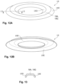
- Fig. 11 shows a rotational position tolerance improving retainer ring 18 of the threaded bayonet connection adapter of Figs. 9 and 10 , having an axial top end face 18A and opposite bottom end face 18B.
- the rotational position tolerance improving retainer ring 18 is provided with a plurality of deformable radially arranged axial projections 18C formed onto on or both of the end faces 18A, 18B.
- the deformable radially arranged axial projections have a rectangular cross-section.
- Figs. 12A, 12B and 13 show another aspect of a rotational position tolerance improving retainer ring 18 of the threaded bayonet connection adapter 14 of Figs. 9 and 10 , having a deformable generally U-shaped cross section ( Fig. 13 ), the rotational position tolerance improving retainer ring 18, according to Figs. 3 , 4 , 7 and 8 , thereby providing for the further deformation of the rotational position tolerance improving retainer ring 18 ( Figs. 12A -13 ) beyond the predetermined final assembly torque to achieve the critical final rotational position for the correct operation of the open (unlocked) and locked position indicators 28, 30 on the filter head 12. This is critical to a correct operation of the open and locked position indicators 28, 30 on the filter head 12.
- the substantial U-shape of the rotational position tolerance improving retainer ring 18 provides for further deformation of the rotational position tolerance improving retainer ring 18 beyond the predetermined final assembly torque to achieve the critical final rotational position for the correct operation of the open and locked position indicators 28, 30 on the filter head 12, the deformation occurring by the deflection of the slanted legs 18D and 18E during compression of the rotational position tolerance improving retainer ring 18 between the threaded bayonet connection adapter 14 and the filter head 12. This is important for a correct operation of the open and locked position indicators 28, 30 on the filter head 12.
- the above-described two-directional drawing process of forming the bayonet connector 14 enables the bayonet connector 14 to have a thicker wall thickness.
- the bayonet connection adapter 14 may achieve better robustness and a longer fatigue life without taking measures such as subjecting the bayonet connection adapter 14 to shot peening after the drawing process or placing a stabilizing ring on top of the bayonet connection adapter 14.
- the cost of the filter head assembly 10 may be minimized relative to other filter head assemblies.
- a filter head assembly includes a filter head and a threaded bayonet connection adapter having a rotational position tolerance improving retainer ring.
- the rotational position tolerance improving retainer ring providing for and enabling further deformation of the rotational position tolerance improving retainer ring beyond the predetermined final assembly torque to achieve the required final rotational position of the threaded bayonet connection adapter for the correct operation of the open and locked position indicators on the filter head.
Landscapes
- Chemical & Material Sciences (AREA)
- Engineering & Computer Science (AREA)
- Chemical Kinetics & Catalysis (AREA)
- Combustion & Propulsion (AREA)
- Mechanical Engineering (AREA)
- General Engineering & Computer Science (AREA)
- Lubrication Details And Ventilation Of Internal Combustion Engines (AREA)
Description
- The present disclosure relates to threaded bayonet connection adapters having rotational position tolerance improving retainer ring, the threaded bayonet connection adapter for connecting an exchangeable filter to a filter head.
- The background description provided here is for the purpose of generally presenting the context of the disclosure.
- Early engine oil filters had a permanent housing containing a replaceable filter. In the mid-1950s, a spin-on filter design was introduced that included a self-contained housing and filter assembly that could be unscrewed from an engine block, discarded, and replaced with a new one. Typically, the spin-on filter must be rotated through several turns to assemble or disassemble the spin-on filter to or from the engine block.
- More recently, automotive companies have developed filter head assemblies that attach an oil filter to an engine via a bayonet connection and that transport oil between the oil filter and the engine. In contrast to a spin-on filter connection, the bayonet connection enables assembling or disassembling an oil filter to or from an engine with a partial turn. Thus, such filter head assemblies reduce the time and effort required to replace an oil filter.
- A filter device comprising a connection head and a replaceable filter unit which are connected by means of a bayonet-type connection device, additionally having a pretensioning element, is described in
WO 2021/078759 A1 . A similar device having guiding means in order to facilitate the connection between connection head and filter unit is disclosed inWO 2015/091665 A1 . - An example of a filter head assembly according to the present disclosure includes a filter head and threaded bayonet connection adapter having a rotational position tolerance improving retainer ring. In one aspect of the invention the filter head is configured to be attached, for example, to an engine block and to enable fluid flow (for example, oil, fuel or other fluids) between, for example, an engine block and a filter connected to the filter head.
- The filter head includes a base and a tubular body protruding from the base, the tubular body defining threads. The threaded bayonet connection adapter is configured to connect the filter to the filter head via a bayonet connection. The threaded bayonet connection adapter includes an annular body defining threads configured to engage the threads on the tubular body of the filter head to attach the threaded bayonet connection adapter to the filter head.
- The rotational position tolerance improving retainer ring is annular. The rotational position tolerance improving retainer ring is arranged on the tubular body and compressed, preferably elastically compressed, between the filter head and the threaded bayonet connection adapter. Generally, the rotational position tolerance improving retainer ring is deformable, i.e. compressible, in axial direction. Compressing the rotational position tolerance improving retainer ring between the filter head and the threaded bayonet adapter allows (first) tightening the threaded bayonet adapter to a predetermined final assembly torque and (second) further tightening the threaded bayonet adapter until a required final rotational position of the threaded bayonet adapter relative to the filter head is achieved. Thereto, the predetermined final assembly torque may be exceeded to some extent. The compressibility of the rotational position tolerance improving retainer ring allows reaching this final rotational position without overloading the other components (such as the filter head and the bayonet adapter). Further, the compressibility of the rotational position tolerance improving retainer ring limits the amount by which the predetermined final assembly torque is exceeded upon reaching the final rotational position.
- In one aspect, the base of the filter head includes a disc-shaped body, and the tubular body protrudes from disc-shaped body along a central axis thereof.
- In one aspect, the threads on the filter head are external threads on an outer radial surface of the tubular body, and the threads on the threaded bayonet connection adapter are internal threads on an inner radial surface of the annular body.
- In one aspect, the threaded bayonet connection adapter further includes tabs protruding radially outward from the annular body thereof. The tabs are configured to be inserted into corresponding slots in an axial end wall of the oil filter.
- In one aspect, the annular body of the threaded bayonet connection adapter includes a first portion having a straight sidewall and a second portion having a curved sidewall. The first portion of the annular body defines the threads on the annular body. The tabs protrude radially outward from an axial end of the second portion of the annular body.
- In one aspect, the filter head assembly further includes a spring. Generally, the spring is arranged on the filter head. The spring is configured to bias the oil filter away from the filter head and thereby inhibit rotation of the tabs on the threaded bayonet connection adapter out of the slots in the oil filter.
- The spring may be arranged between the threaded bayonet connection adapter and the filter head. The threaded bayonet connection adapter may hold the spring in place relative to the filter head.
- In one aspect, the rotational position tolerance improving retainer ring is configured to be assembled between the bayonet connector and the filter head and to hold the spring in place relative to the filter head.
- In one aspect, the spring includes straight segments disposed in a common plane and U-shaped segments joining the straight segments to one another and protruding out of the plane. The straight segments of the spring are configured to be clamped between the retainer ring and the filter head, and the U-shaped segments of the spring are configured to apply a biasing force to the axial end wall of the oil filter urging the oil filter away from the filter head. Preferably, the straight segments are held clamped between the rotational position tolerance improving retainer ring and the filter head.
- In one aspect, the rotational position tolerance improving retainer ring is made of aluminum, brass, copper, or combinations thereof.
- In one aspect, the rotational position tolerance improving retainer ring is configured to deform under a compression load applied to the threaded bayonet connection adapter when the threaded bayonet connection adapter is rotated on the tubular body and tightened onto the filter head to a predetermined final assembly torque. In other words, the rotational position tolerance improving retainer ring is configured to advantageously deform under a load applied by the threaded bayonet connection adapter when the threaded bayonet connection adapter is tightened onto the filter head to at least a predetermined final assembly torque. Preferably, upon reaching the predetermined final assembly torque, the rotational position tolerance improving retainer ring is configured to permit further rotation by further deformation at an applied torque in a region near the predetermined final assembly torque so as to permit further rotation to provide rotational alignment of the threaded bayonet connection adapter to a required rotational position on the filter head. In other words, the rotational position tolerance improving retainer ring is configured to be further deformable to permit required further rotation beyond the predetermined final assembly torque to align the threaded bayonet connection adapter to a required rotational position on the filter head, in particular such that open and locked position indications on the filter head agree with the actual open and locked positions of the filter element (the oil filter) on the filter head. This enhances correct operation of the open and locked position indicators on the filter head.
- In one aspect, the rotational position tolerance improving retainer ring includes an axial top end face and an axial bottom end face. A plurality of deformable radially extending axial projections are formed on the axial top end face, the axial bottom end face; or on both of the axial top end face the axial bottom end face. The axial projections project axially outwardly away from the rotational position tolerance improving retainer ring.
- In one aspect, the rotational position tolerance improving retainer ring has a substantially U-shaped cross-section and the rotational position tolerance improving retainer ring has an annular center end face, an annular radially outer slanted leg, and an annular radially inner slanted leg. The slanted legs together with the annular center end face form the substantially U-shaped cross-section. The U-shaped cross-section provides the further rotation of the rotational position tolerance improving retainer ring beyond the predetermined final assembly torque to achieve the required rotational position on the filter head by the further deformation and deflection of the slanted legs.
- In one aspect, at least the annular center end face includes a plurality of concentrically arranged and radially spaced projecting rings formed on the annular center end face and projecting axially outwardly therefrom. The further rotation of the rotational position tolerance improving retainer ring is further provided by further deformation of the plurality of concentrically arranged and radially spaced projecting rings.
- In one aspect, the tabs have V-shaped lower surfaces. The V-shaped lower surfaces are configured to engage corresponding V-shaped upper surfaces of the axial end wall of the oil filter adjacent to the slots to inhibit rotation of the tabs out of the slots.
- In one aspect, the filter head assembly is configured to hold the oil filter in place relative to the engine block when the axial end wall of the oil filter is pressed toward the filter head to overcome a biasing force of the spring and the oil filter is rotated relative to the filter head until the tabs on the bayonet connector are received in the slots on the axial end wall of the oil filter and the V-shaped lower surfaces on the tabs engage the V-shaped upper surfaces of the axial end wall.
- In one aspect, the filter head is made of aluminum, and the bayonet connector is made of steel.
- In one aspect, the threads on the filter head are external threads on an outer radial surface of the tubular body of the filter head, the threads on the threaded bayonet connection adapter are internal threads on an inner radial surface of the annular body of the threaded bayonet connection adapter, and the threaded bayonet connection adapter further includes tabs protruding radially outward from the annular body of the bayonet connector. The tabs are configured to be inserted into corresponding slots in an axial end wall of the oil filter.
- An example of a threaded bayonet connection adapter according to the present disclosure is for connecting an oil filter to a filter head via a bayonet connection. The threaded bayonet connection adapter includes an annular body and tabs. The annular body defines threads configured to engage threads on the filter head to attach the threaded bayonet connection adapter to the filter head. The tabs protrude from the annular body and are configured to be inserted into corresponding slots in an axial end wall of the oil filter to attach the oil filter to the threaded bayonet connection adapter.
- In one aspect, the threads on the threaded bayonet connection adapter are internal threads on an inner radial surface of the annular body, and the tabs protrude radially outward from the annular body.
- In one aspect, the annular body includes a first portion having a straight sidewall and a second portion having a curved sidewall. The first portion of the annular body defines the threads on the annular body. The tabs protrude radially outward from an axial end of the second portion of the annular body.
- In one aspect, the tabs have V-shaped lower surfaces configured to engage corresponding V-shaped upper surfaces of the axial end wall of the oil filter adjacent to the slots to inhibit rotation of the tabs out of the slots.
- An example of a method of forming a threaded bayonet connection adapter for connecting an oil filter to a filter head via a bayonet connection according to the present disclosure includes drawing a blank in a first direction to form at least a portion of an annular body, and drawing the blank in a second direction to form tabs protruding radially outward from the annular body. The annular body and the tabs collectively make up the threaded bayonet connection adapter. The tabs are configured to be inserted into corresponding slots in an axial end wall of the oil filter to attach the oil filter to the threaded bayonet connection adapter and thereby to the filter head.
- In one aspect, the method further includes drawing the blank in the first direction to form a first portion of the annular body, and drawing the blank in the second direction to form a second portion of the annular body and the tabs. The tabs protrude radially outward from an axial end of the second portion of the annular body.
- In one aspect, the method further includes forming internal threads on an inner radial surface of the annular body. The internal threads on the annular body are configured to engage external threads on the filter head to attach the threaded bayonet connection adapter to the filter head.
- In one aspect, the second direction in which the blank is drawn is opposite of the first direction in which the blank is drawn.
- The invention further relates to a filter device comprising the filter head assembly and an oil filter.
- Furthermore, the invention relates to an engine assembly comprising an engine block and the filter head assembly. Preferably, the engine assembly further comprises an oil filter.
- Further areas of applicability of the present disclosure will become apparent from the detailed description, the claims and the drawings. The detailed description and specific examples are intended for purposes of illustration only and are not intended to limit the scope of the disclosure.
- The present disclosure will become more fully understood from the detailed description and the accompanying drawings, wherein:
-
FIG. 1 is a perspective view of a filter head assembly according to the present disclosure including a filter head and a threaded bayonet connection adapter with a rotational position tolerance improving retainer ring for connecting an oil filter to the filter head, with the oil filter shown in its unlocked position relative to the filter head; -
FIG. 2 is a perspective view of a filter head assembly according to the present disclosure including a filter head and a threaded bayonet connection adapter and rotational position tolerance improving retainer ring for connecting an oil filter to the filter head, with the oil filter shown in its locked position relative to the filter head; -
FIG. 3 is an exploded perspective view of the filter head assembly ofFIG. 1 ; -
FIG. 4 is a perspective view of the filter head assembly ofFIG. 1 and a portion of the oil filter ofFIG. 1 ; -
FIG. 5 is a perspective view of the filter head assembly ofFIG. 1 and an axial end wall of the oil filter ofFIG. 1 ; -
FIG. 6 is a section view of the filter head assembly ofFIG. 1 and a portion of the oil filter ofFIG. 1 ; -
FIG. 7 is a sectioned perspective view of the filter head assembly ofFIG. 1 ; -
FIG. 8 is a top view of the filter head assembly ofFIG. 1 illustrating the angular orientation of the threaded bayonet connection adapter relative to the filter head; -
FIG. 9 is a perspective view of the threaded bayonet connection adapter ofFIG. 1 ; -
FIG. 10 is a side view of the threaded bayonet connection adapter ofFIG. 1 ; -
Fig. 11 is a schematic top perspective view of a rotational position tolerance improving retainer ring of the threaded bayonet connection adapter offigs 9 and 10 , having radially elongated axially projecting projections on one or both axial faces of the rotational position tolerance improving retainer ring ofFigs. 3 ,4 ,7 and8 , thereby providing for further deformation of the rotational position tolerance improving retainer ring beyond the predetermined final assembly torque to achieve the final rotational position for the correct operation of the open and locked position indicators on the filter head; -
Fig. 12A is a schematic top perspective view of another aspect of the rotational position tolerance improving retainer ring of the threaded bayonet connection adapter ofFigs. 9 and 10 , having a deformable U-shaped cross section, the rotational position tolerance improving retainer ring, and according toFigs. 3 ,4 ,7 and8 , thereby providing for the further deformation of the rotational position tolerance improving retainer ring beyond the predetermined final assembly torque to achieve the final rotational position for the correct operation of the open and locked position indicators on the filter head; -
Fig. 12B is a schematic bottom perspective view of a rotational position tolerance improving retainer ring of the threaded bayonet connection adapter ofFig. 12A ; -
Fig. 13 is a sectional view of the rotational position tolerance improving retainer ring ofFigs. 12A and 12B , taken alongsection line 13; and -
Fig. 14 is a schematic top perspective view of another aspect of the rotational position tolerance improving retainer ring of the threaded bayonet connection adapter ofFigs. 9 and 10 , having a plurality of concentrically arranged and radially spaced axially projecting rings formed on the axial face of the rotational position tolerance improving retainer ring, thereby providing for further deformation of the rotational position tolerance improving retainer ring beyond the predetermined final assembly torque to achieve the final rotational position for the correct operation of the open and locked position indicators on the filter head. - In the drawings, reference numbers may be reused to identify similar and/or identical elements.
- Referring now to
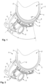
FIGS. 1 through 3 , afilter head assembly 10 includes afilter head 12, a threadedbayonet connection adapter 14, aspring 16, and a rotational position tolerance improving retainer ring 18 (Figs. 3 and11-14 ). Thefilter head 12 is attachable to an engine block (not shown) using, for example, fasteners. When thefilter head 12 is attached to the engine block, thefilter head 12 enables oil flow between the engine block and anoil filter 20 connected to thefilter head 12. Thefilter head 12 may be made of aluminum. - The
oil filter 20 filters engine oil that flows through theoil filter 20. Theoil filter 20 is rotatable relative to thefilter head 12 between an unlocked position shown inFIG. 1 and a locked position shown inFIG. 2 . When theoil filter 20 is in its locked position, thefilter head 12 secures theoil filter 20 to the engine block. When theoil filter 20 is in its unlocked position, theoil filter 20 can be removed from thefilter head 12. In the example shown, theoil filter 20 is rotated through an angle A1 degrees to adjust theoil filter 20 between its unlocked and locked positions. - The
oil filter 20 includes acylindrical sidewall 22 and anaxial end wall 24. Thecylindrical sidewall 22 of theoil filter 20 has alock indicator 26, and thefilter head 12 has anunlock indicator 28 and a lockedindicator 30. Alignment of thelock indicator 26 on theoil filter 20 with theunlock indicator 28 on thefilter head 12 as shown inFIG. 1 indicates that theoil filter 20 is not locked to thefilter head 12. Alignment of thelock indicator 26 on theoil filter 20 with thelock indicator 30 on thefilter head 12 as shown inFIG. 2 indicates that the oil filter is locked to thefilter head 12. The rotational position tolerance improvingretainer ring 18 is critical to achieving the correct alignment of the threadedbayonet connection adapter 14 on thefilter head 12 so the locked and unlocked positions correctly correspond to the locked and unlocked indications on the filter head. - With additional reference to
FIGS. 4 and5 , thefilter head 12 includes anengine attachment portion 32 and afilter support portion 34. Theengine attachment portion 32 of thefilter head 12 includes a base 36 having a disk-shapedbody 38 andtabs 40 protruding from an outerradial surface 42 of the disk-shapedbody 38. The disk-shapedbody 38 of theengine attachment portion 32 has anengine mounting surface 44 that abuts the engine block when thefilter head 12 is attached thereto. - The
tabs 40 of theengine attachment portion 32 can be used to locate thefilter head 12 relative to the engine block when attaching thefilter head 12 thereto. As best shown inFIG. 5 , thebase 36 of theengine attachment portion 32 defines aninlet port 46 that receives oil from the engine block and anoutlet port 48 that returns filtered oil to the engine block. - The
filter support portion 34 of thefilter head 12 includes a base 50 having a disk-shapedbody 52, atubular body 54 protruding from thebase 50 along acentral axis 56 thereof, and alock indicator tab 58 protruding from an outerradial surface 60 of thebase 50. Thebase 50 of thefilter support portion 34 further includes a spring retention boss 62 (FIG. 3 ) protruding from atop surface 64 of the disk-shapedbody 52 anddefining grooves 66 that receive thespring 16. Thetubular body 54 of thefilter support portion 34 definesexternal threads 68 on an outerradial surface 70 thereof. The unlock and lockindicators lock indicator tab 58. - The threaded
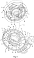
bayonet connection adapter 14 connects theoil filter 20 to thefilter head 12 via a bayonet connection. The threadedbayonet connection adapter 14 may be made of steel. As best shown inFIG. 3 , the threadedbayonet connection adapter 14 includes anannular body 72 andtabs 74 protruding radially outward from theannular body 72. Theannular body 72 of the threadedbayonet connection adapter 14 includes afirst portion 76 having a straight sidewall and asecond portion 78 having a curved sidewall. An innerradial surface 79 of theannular body 72 definesinternal threads 80 that engage theexternal threads 68 on thetubular body 54 of thefilter head 12 as shown inFIGS. 6 and7 . - The
tabs 74 of the threadedbayonet connection adapter 14 protrude radially outward from anaxial end 82 of thesecond portion 78 of theannular body 72. As best shown inFIGS. 4 and5 , to secure theoil filter 20 to thefilter head 12, theoil filter 20 is placed onto the threadedbayonet connection adapter 14 so that thetabs 74 of the threadedbayonet connection adapter 14 project throughslots 84 in theaxial end wall 24 of theoil filter 20 adjacent to first ends 86 thereof. Theoil filter 20 is then rotated until thetabs 74 of the threadedbayonet connection adapter 14 are adjacent to second ends 88 of theslots 84 in theaxial end wall 24 of theoil filter 20. Rotating theoil filter 20 so that thetabs 74 on thebayonet connector 14 move through theslots 84 in theaxial end wall 24 of theoil filter 20 from the first ends 86 thereof to the second ends 88 thereof adjusts theoil filter 20 from its unlocked position to its locked position. - The
tabs 74 of the threadedbayonet connection adapter 14 have V-shapedlower surfaces 90 that engage corresponding V-shapedupper surfaces 92 of theaxial end wall 24 of theoil filter 20 adjacent to theslots 84 in theaxial end wall 24. The V-shapedlower surfaces 90 of the threadedbayonet connection adapter 14 engage the V-shapedupper surfaces 92 of theoil filter 20 when thetabs 74 of the threadedbayonet connection adapter 14 are adjacent to the second ends 88 of theslots 84. The engagement between the V-shapedlower surfaces 90 of the threadedbayonet connection adapter 14 and the V-shapedupper surfaces 92 of theoil filter 20 inhibits rotation of thetabs 74 out of theslots 84 and thereby maintain theoil filter 20 in its locked position. - Referring now to
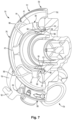
FIGS. 3 through 7 , thespring 16 biases theoil filter 20 away from thefilter head 12 and thereby further inhibits rotation of thetabs 74 on the threadedbayonet connection adapter 14 out of theslots 84 in theoil filter 20. Thespring 16 may be made of steel. Thespring 16 includesstraight segments 94 disposed in a common plane andu-shaped segments 96 joining thestraight segments 94 to one another and protruding out of the plane. Thestraight segments 94 of thespring 16 are inserted into thegrooves 66 in thefilter head 12 and clamped between the tolerance improving retainer ring 18 (Figs. 3 and11-14 ) and thefilter head 12. Theu-shaped segments 96 of thespring 16 apply a biasing force to theaxial end wall 24 of theoil filter 20 urging theoil filter 20 away from thefilter head 12. - To secure the
oil filter 20 to thefilter head assembly 10, theoil filter 20 is oriented in its unlocked position with respect to thefilter head 12, and theaxial end wall 24 of theoil filter 20 is pressed toward thefilter head 12 to overcome a biasing force of thespring 16. Theoil filter 20 is then rotated relative to thefilter head 12 until thetabs 74 on the threadedbayonet connection adapter 14 are received in theslots 84 on theaxial end wall 24 and the V-shapedlower surfaces 90 on thetabs 74 engage the V-shapedupper surfaces 92 of theaxial end wall 24. When this occurs, theoil filter 20 is in its locked position with respect to thefilter head 12, and thefilter head assembly 10 holds theoil filter 20 in place relative to the engine block. - As best shown in
FIGS. 6 and7 , the rotational position tolerance improvingretainer ring 18 according to any ofFigs. 3 or11-14 is assembled between thebayonet connection adapter 14 and thefilter head 12. The rotational position tolerance improvingretainer ring 18 holds thespring 16 in place relative to thefilter head 12. To assemble thefilter head assembly 10, thestraight segments 94 of thespring 16 are inserted into thegrooves 66 in thefilter head 12, and theretainer ring 18 is placed over thestraight segments 94 of thespring 16. The threadedbayonet connection adapter 14 is then threaded onto thefilter head 12 by engaging theinternal threads 80 on the threadedbayonet connection adapter 14 with theexternal threads 68 on thefilter head 12 and rotating the threadedbayonet connection adapter 14bayonet connector 14 until theretainer ring 18 is clamped between thebayonet connector 14 and thefilter head 12. - The threaded
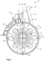
bayonet connection adapter 14 is threaded onto thefilter head 12 until the torque applied to the threadedbayonet connection adapter 14 is within a predetermined torque range. The threadedbayonet connection adapter 14 is then rotated, if needed, a further rotational distance until a critical predetermined angular orientation of the threadedbayonet connection adapter 14 with respect to thefilter head 12 is correctly achieved.FIG. 8 illustrates an example of such a predetermined angular orientation of the threadedbayonet connection adapter 14. InFIG. 8 , one of thetabs 74 on the threadedbayonet connection adapter 14 is oriented at an angle A2 of 3 degrees with respect to avisual alignment nub 98 on thefilter head 12. In various implementations, the predetermined angular orientation of the threadedbayonet connection adapter 14 may be defined using other features of thefilter head 12, for example thelock indicator tab 58. - Since the threaded
bayonet connection adapter 14 is threaded onto thefilter head 12, there are multiple factors that affect the final assembly orientation of thebayonet connector 14. These factors include the starting location of theinternal threads 80 of thebayonet connector 14, the starting location of theexternal threads 68 on thefilter head 12, and the thickness of theretainer ring 18, and the specific rotational position tolerance improvingretainer ring 18 configuration selected, as shown onFigs. 11-14 . Due to the stack up of tolerances associated with these factors, without certain measures, the threadedbayonet connection adapter 14 may not be positioned at the predetermined angular orientation with respect to thefilter head 12 when thefilter head assembly 10 is fully assembled at the required torque. In turn, thelock indicator 26 on theoil filter 20 may not be correctly aligned with alock indicator 30 on thefilter head 12 when theoil filter 20 is secured to thefilter head 12. - Due to the stack up of tolerances of these components, there could be too much variation in the final orientation of the threaded
bayonet connection adapter 14 relative to thefilter head 12. The threadedbayonet connection adapter 14 could end up being out of position potentially for some assemblies, such that the rotational locked/unlocked positions of thefilter 20 on thebayonet connector 14 do not properly correspond to the locked/unlocked positions on thelock indicator tab 58. For proper and reliable mounting of thefilter 20, it is critical that the rotational locked/unlocked positions of thefilter 20 on thebayonet connector 14 properly correspond to the locked/unlocked positions indicated on thelock indicator tab 58 of thefilter head 12. This is accomplished with the rotational position tolerance improving retainer rings 18 as disclosed inFigs. 11-14 . - This critical requirement drives the need for an inventive scheme that will allow for a large window of assembly torque in order to be able to overcome these stack up tolerances, and enables and provides the threaded
bayonet connection adapter 14 to be fixedly mounted with required frictional restraint onto thefilter head 12 in the required correct position. - In order to achieve this relatively flat "torque vs rotational angle" behavior, it has been found preferable to choose a material with a comparatively low Young's modulus for the rotational position tolerance improving
retainer ring 18. A low Young's Modulus indicates a low amount of force required for a set amount of deformation. In our development testing, we have found that 3003 H14 aluminum provided the desired relatively flat "torque vs rotational angle". In our tests, for example, flat stainless steel and aluminum rotational position tolerance improving retainer rings were assembled at a 100 Nm torque. Between the two flat retainer rings, the bayonet connector's final position can be rotated 10% further with the aluminum ring, providing flatter "torque vs angle" behavior with the aluminum rings, thereby allowing the rotational locked/unlocked positions of thefilter 20 on thebayonet connector 14 to properly correspond to the locked/unlocked indicator 58 of thefilter head 12. However, as the proper rotational alignment of the alignment of the threadedbayonet connection adapter 14 relative to thefilter head 12 is important for the correct open/closed indicator operation, an even wider range of the flatter "torque vs angle" behavior is desired. - To address the issue noted above, the
retainer ring 18 is designed to yield a large window of assembly torque in order to be able to overcome the stack up of tolerances. For example, theretainer ring 18 may be made of a material (e.g., a metal) with a low modulus of elasticity (e.g., less than or equal to 150 gigapascals (GPa) such as aluminum, brass, copper, or combinations thereof. In a specific example, the rotational position tolerance improvingretainer ring 18 is preferably made of 3003 aluminum with a modulus of elasticity of 68.9 GPa. Such a material would require applying only a low amount of tightening torque to thebayonet connector 14 in order to deform theretainer ring 18 by a predetermined amount. Thus, theretainer ring 18 may be designed to deform under low load and thereby enable both tightening thebayonet connector 14 to within the predetermined torque range and adjusting thebayonet connector 14 to the predetermined angular orientation. -
Fig. 11 shows a rotational position tolerance improvingretainer ring 18 of the threaded bayonet connection adapter ofFigs. 9 and 10 , having an axial top end face 18A and oppositebottom end face 18B. InFig. 11 . The rotational position tolerance improvingretainer ring 18 is provided with a plurality of deformable radially arrangedaxial projections 18C formed onto on or both of the end faces 18A, 18B. Preferably, the deformable radially arranged axial projections have a rectangular cross-section. The deformable radially arrangedaxial projections 18C provide for a larger flattened torque range after the threadedbayonet connection adapter 14 is tightened onto thefilter head 12 to at least a predetermined final assembly torque, providing additional rotation of the threadedbayonet connection adapter 14 on thefilter head 12 to the required rotational position on thefilter head 12 such the open and locked position indications on the filter head agree with the actual open and locked positions of the filter element (oil filter 20) on thefilter head 12. This is important for a correct operation of the open and lockedposition indicators filter head 12. -
Figs. 12A, 12B and 13 show another aspect of a rotational position tolerance improvingretainer ring 18 of the threadedbayonet connection adapter 14 ofFigs. 9 and 10 , having a deformable generally U-shaped cross section (Fig. 13 ), the rotational position tolerance improvingretainer ring 18, according toFigs. 3 ,4 ,7 and8 , thereby providing for the further deformation of the rotational position tolerance improving retainer ring 18 (Figs. 12A -13 ) beyond the predetermined final assembly torque to achieve the critical final rotational position for the correct operation of the open (unlocked) and lockedposition indicators filter head 12. This is critical to a correct operation of the open and lockedposition indicators filter head 12. As shown inFigs. 12A, 12B and 13 , the rotational position tolerance improvingretainer ring 18 ofFig. 12A is substantially U-shaped, having a center end face 18G, a radially outerslanted leg 18E and a radially innerslanted leg 18D. The substantial U-shape of the rotational position tolerance improvingretainer ring 18 provides for further deformation of the rotational position tolerance improvingretainer ring 18 beyond the predetermined final assembly torque to achieve the critical final rotational position for the correct operation of the open and lockedposition indicators filter head 12, the deformation occurring by the deflection of theslanted legs retainer ring 18 between the threadedbayonet connection adapter 14 and thefilter head 12. This is important for a correct operation of the open and lockedposition indicators filter head 12. -
Fig. 14 is a schematic top perspective view of another aspect of the rotational position tolerance improvingretainer ring 18 of the threaded bayonet connection adapter ofFigs. 9 and 10 . Similar toFigs. 12A, 12B and 13 and including a plurality of concentrically arranged and radially spaced projectingrings 18F formed on the axial face of the rotational position tolerance improvingretainer ring 18, thereby providing for further deformation of the rotational position tolerance improvingretainer ring 18 beyond the predetermined final assembly torque to achieve the critical final rotational position for the correct operation of the open and lockedposition indicators filter head 12. As shown inFig. 14 , the rotational position tolerance improvingretainer ring 18 ofFig. 14 is substantially U-shaped, having a center end face 18G, a radially outerslanted leg 18E and a radially innerslanted leg 18D. The plurality of concentrically arranged and radially spaced projectingrings 18F are arranged on at least thecenter end face 18G and may be arranged on one or both of theslanted legs - Referring now to
FIG. 9 and 10 , an example method of forming thebayonet connector 14 will now be described. The method includes drawing a blank in afirst direction 100 to form thefirst portion 76 of theannular body 72 and drawing the blank in asecond direction 102 to form thesecond portion 78 of theannular body 72 and thetabs 74. Thesecond direction 102 is opposite of thefirst direction 100. The method further includes forming theinternal threads 80 on the innerradial surface 79 of theannular body 72 using, for example, a tap and die. - The example method of forming the
bayonet connector 14 described above is enabled at least in part by the threaded connection between thebayonet connector 14 and thefilter head 12. Without this threaded connection, a bayonet connector (not shown) may need to include fastener tabs through which fasteners may be inserted to attach the bayonet connector to thefilter head 12. The fastener tabs may need to be disposed within a common plane, and therefore the remainder of the bayonet connector may be formed by deep drawing a blank in a single direction away from that plane. As a result, the wall thickness of the bayonet connector may be limited, and the bayonet connector may experience a thinning effect during the drawing operation that may lead to microcracks in the bayonet connector. The fatigue life of the bayonet connector may be improved by subjecting the bayonet connector to shot peening after the drawing process and placing a stabilizing ring (not shown) on top of the bayonet connector. However, such measures increase the cost and complexity of the overall assembly. - In contrast the such a single-direction drawing process, the above-described two-directional drawing process of forming the
bayonet connector 14 enables thebayonet connector 14 to have a thicker wall thickness. In turn, thebayonet connection adapter 14 may achieve better robustness and a longer fatigue life without taking measures such as subjecting thebayonet connection adapter 14 to shot peening after the drawing process or placing a stabilizing ring on top of thebayonet connection adapter 14. As a result, the cost of thefilter head assembly 10 may be minimized relative to other filter head assemblies. - In summary, a filter head assembly includes a filter head and a threaded bayonet connection adapter having a rotational position tolerance improving retainer ring. The rotational position tolerance improving retainer ring providing for and enabling further deformation of the rotational position tolerance improving retainer ring beyond the predetermined final assembly torque to achieve the required final rotational position of the threaded bayonet connection adapter for the correct operation of the open and locked position indicators on the filter head.
Claims (16)
- A filter head assembly (10) comprising:a filter head (12) configured to be attached to an engine block and to enable oil flow between the engine block and an oil filter (20) connected to the filter head (12), the filter head (12) including a base (36),characterized in that the filter head (12) further includesa tubular body (54) protruding from the base (36), the tubular body (54) defining threads (68); anda threaded bayonet connection adapter (14) configured to connect the oil filter (20) to the filter head (12) via a bayonet connection, the bayonet connection adapter (14) includingan annular body (72) defining threads (80) configured to engage the threads (68) on the tubular body (54) of the filter head (12) to attach the bayonet connection adapter (14) to the filter head (12);an axially deformable rotational position tolerance improving retainer ring (18), which is annular and is arranged on the tubular body (54) and compressed, preferably elastically compressed, between the filter head (12) and the threaded bayonet connection adapter (14).
- The filter head assembly (10) according to claim 1, wherein:
the rotational position tolerance improving retainer ring (18) includesan axial top end face (18A); andan axial bottom end face (18B);wherein a plurality of deformable radially extending axial projections (18C) are formed on the axial top end face (18A), the axial bottom end face (18B); or on both of the axial top end face (18A) and the axial bottom end face (18B); wherein the axial projections (18C) project axially outwardly away from the rotational position tolerance improving retainer ring (18). - The filter head assembly (10) according to claim 1 or 2, wherein:
the rotational position tolerance improving retainer ring (18) has a substantially U-shaped cross-section, the rotational position tolerance improving retainer ring (18) having:an annular center end face (18G);an annular radially outer slanted leg (18E);an annular radially inner slanted leg (18D);wherein the slanted legs (18D, 18E) together with the annular center end face (18G) form the substantially U-shaped cross-section. - The filter head assembly (10) according to claim 3, wherein:
at least the annular center end face (18G) includes
a plurality of concentrically arranged and radially spaced projecting rings (18F) formed on the annular center end face (18G) and projecting axially outwardly therefrom. - The filter head assembly (10) according to any of claims 1 to 4, wherein:the base (36) of the filter head (12) includes a disc-shaped body (38); andthe tubular body (54) protrudes from disc-shaped body (38) along a central axis thereof.
- The filter head assembly (10) according to any of claims 1 to 5, wherein:the threads (68) on the filter head are external threads on an outer radial surface (70) of the tubular body (54); andthe threads (80) on the threaded bayonet connection adapter (14) are internal threads on an inner radial surface (79) of the annular body (72).
- The filter head assembly (10) according to any of claims 1 to 6, wherein
the threaded bayonet connection adapter (14) further includes
tabs (74) protruding radially outward from the annular body (72) thereof. - The filter head assembly (10) according to claim 7, wherein
the annular body (72) of the threaded bayonet connection adapter (14) includesa first portion (76) having a straight sidewall; anda second portion (78) having a curved sidewall;the first portion (76) of the annular body (72) defining the threads (80) on the annular body (72),the tabs (74) protruding radially outward from an axial end (82) of the second portion (78) of the annular body (72). - The filter head assembly (10) according to claim 7 or 8 further comprising a spring (16) arranged on the filter head (12).
- The filter head assembly (10) according to claim 9, wherein the spring (16) is arranged between the threaded bayonet connection adapter (14) and the filter head (12).
- The filter head assembly (10) according to claim 10, wherein:
the spring (16) includesstraight segments (94) disposed in a common plane; andU-shaped segments (96) joining the straight segments (94) to one another and protruding out of the plane;preferably wherein the straight segments (94) are held clamped between the rotational position tolerance improving retainer ring (18) and the filter head (12). - The filter head assembly (10) according to any of claims 9 to 11, wherein the tabs (74) have V-shaped lower surfaces (90).
- The filter head assembly (10) according to claim 12, wherein the filter head assembly (10) is configured to hold the oil filter (20) in place relative to the engine block when the axial end wall (24) of the oil filter (20) is pressed toward the filter head (12) to overcome a biasing force of the spring (16) and the oil filter (20) is rotated relative to the filter head (12) until the tabs (74) on the bayonet connection adapter (14) are received in the slots (84) on the axial end wall (24) of the oil filter (20) and the V-shaped lower surfaces (90) on the tabs (74) engage V-shaped upper surfaces (92) of the axial end wall (24).
- The filter head assembly (10) according to any of claims 1 to 13, wherein the rotational position tolerance improving retainer ring (18) is made of aluminum, brass, copper, or combinations thereof.
- The filter head assembly (10) according to any of claims 1 to 14, wherein:the filter head (12) is made of aluminum; andthe threaded bayonet connection adapter (14) is made of steel.
- The filter head assembly (10) according to any of claims 1 to 15, wherein:the threads (68) on the filter head (12) are external threads on an outer radial surface (70) of the tubular body (54) of the filter head (12); andthe threads (80) on the threaded bayonet connection adapter (14) are internal threads on an inner radial surface (79) of the annular body (72) of the threaded bayonet connection adapter (14); andthe threaded bayonet connection adapter (14) further includes tabs (74) protruding radially outward from the annular body (72) of the threaded bayonet connection adapter (14).
Applications Claiming Priority (1)
| Application Number | Priority Date | Filing Date | Title |
|---|---|---|---|
| US17/829,830 US12311293B2 (en) | 2022-02-10 | 2022-06-01 | Filter head assembly having a threaded bayonet connector adapter with a position tolerance improving retainer ring |
Publications (2)
| Publication Number | Publication Date |
|---|---|
| EP4286028A1 EP4286028A1 (en) | 2023-12-06 |
| EP4286028B1 true EP4286028B1 (en) | 2025-07-02 |
Family
ID=86387059
Family Applications (1)
| Application Number | Title | Priority Date | Filing Date |
|---|---|---|---|
| EP23173743.8A Active EP4286028B1 (en) | 2022-06-01 | 2023-05-16 | Filter head assembly having a threaded bayonet connector adapter with a position tolerance improving retainer ring |
Country Status (3)
| Country | Link |
|---|---|
| US (1) | US20250249383A1 (en) |
| EP (1) | EP4286028B1 (en) |
| CN (1) | CN117145670A (en) |
Family Cites Families (3)
| Publication number | Priority date | Publication date | Assignee | Title |
|---|---|---|---|---|
| DE102013011620B4 (en) * | 2013-07-12 | 2016-12-22 | Mann + Hummel Gmbh | Filter device for fluid and replaceable filter |
| DE102013021298A1 (en) * | 2013-12-19 | 2015-06-25 | Mann + Hummel Gmbh | Treatment device for the treatment of in particular liquid fluids and treatment element of a treatment device |
| JP7739275B2 (en) * | 2019-10-25 | 2025-09-16 | マン ウント フンメル ゲゼルシャフト ミット ベシュレンクテル ハフツング | Treatment device for treating fluids, in particular liquids, and treatment unit and connection head of the treatment device - Patents.com |
-
2023
- 2023-05-16 EP EP23173743.8A patent/EP4286028B1/en active Active
- 2023-06-01 CN CN202310644678.2A patent/CN117145670A/en active Pending
-
2025
- 2025-04-25 US US19/189,795 patent/US20250249383A1/en active Pending
Also Published As
| Publication number | Publication date |
|---|---|
| EP4286028A1 (en) | 2023-12-06 |
| CN117145670A (en) | 2023-12-01 |
| US20250249383A1 (en) | 2025-08-07 |
Similar Documents
| Publication | Publication Date | Title |
|---|---|---|
| US20220258082A1 (en) | Torsional No Filter No Run System and Method | |
| US11305213B2 (en) | Filter element with torsion lock and/or sliding piston, assembly and methods | |
| EP1558357B1 (en) | Eccentric interference retention system for a filter cartridge | |
| US20250177893A1 (en) | Endplate with guide feature | |
| US11413559B2 (en) | J-hook filter assembly | |
| EP1017468A1 (en) | Arrangement and method for sealing fluid filters | |
| US11033843B2 (en) | Press-in filter spud that is free to spin | |
| US7695618B2 (en) | Filter cartridge and mounting system therefor having foolproofing means | |
| CN115671832B (en) | Filter assembly with internal filter element with top rib | |
| EP4286028B1 (en) | Filter head assembly having a threaded bayonet connector adapter with a position tolerance improving retainer ring | |
| EP2753854B1 (en) | Safety head | |
| US12311293B2 (en) | Filter head assembly having a threaded bayonet connector adapter with a position tolerance improving retainer ring | |
| JP2000033206A (en) | Filter device | |
| CN115135397B (en) | Easy-lock spin-on filters | |
| JPH0685007U (en) | Fluid filter | |
| US12467454B2 (en) | Fluid end of a hydraulic fluid pump and method of assembling the same | |
| EP4375534B1 (en) | Coil assembly for a damping valve | |
| WO2022143117A1 (en) | Functional assembly having nfc tag, functional module, and mounting base |
Legal Events
| Date | Code | Title | Description |
|---|---|---|---|
| PUAI | Public reference made under article 153(3) epc to a published international application that has entered the european phase |
Free format text: ORIGINAL CODE: 0009012 |
|
| STAA | Information on the status of an ep patent application or granted ep patent |
Free format text: STATUS: THE APPLICATION HAS BEEN PUBLISHED |
|
| AK | Designated contracting states |
Kind code of ref document: A1 Designated state(s): AL AT BE BG CH CY CZ DE DK EE ES FI FR GB GR HR HU IE IS IT LI LT LU LV MC ME MK MT NL NO PL PT RO RS SE SI SK SM TR |
|
| STAA | Information on the status of an ep patent application or granted ep patent |
Free format text: STATUS: REQUEST FOR EXAMINATION WAS MADE |
|
| 17P | Request for examination filed |
Effective date: 20240521 |
|
| RBV | Designated contracting states (corrected) |
Designated state(s): AL AT BE BG CH CY CZ DE DK EE ES FI FR GB GR HR HU IE IS IT LI LT LU LV MC ME MK MT NL NO PL PT RO RS SE SI SK SM TR |
|
| GRAP | Despatch of communication of intention to grant a patent |
Free format text: ORIGINAL CODE: EPIDOSNIGR1 |
|
| STAA | Information on the status of an ep patent application or granted ep patent |
Free format text: STATUS: GRANT OF PATENT IS INTENDED |
|
| INTG | Intention to grant announced |
Effective date: 20250221 |
|
| GRAS | Grant fee paid |
Free format text: ORIGINAL CODE: EPIDOSNIGR3 |
|
| GRAA | (expected) grant |
Free format text: ORIGINAL CODE: 0009210 |
|
| STAA | Information on the status of an ep patent application or granted ep patent |
Free format text: STATUS: THE PATENT HAS BEEN GRANTED |
|
| AK | Designated contracting states |
Kind code of ref document: B1 Designated state(s): AL AT BE BG CH CY CZ DE DK EE ES FI FR GB GR HR HU IE IS IT LI LT LU LV MC ME MK MT NL NO PL PT RO RS SE SI SK SM TR |
|
| REG | Reference to a national code |
Ref country code: GB Ref legal event code: FG4D |
|
| REG | Reference to a national code |
Ref country code: CH Ref legal event code: EP |
|
| REG | Reference to a national code |
Ref country code: DE Ref legal event code: R096 Ref document number: 602023004433 Country of ref document: DE |
|
| REG | Reference to a national code |
Ref country code: IE Ref legal event code: FG4D |
|
| P01 | Opt-out of the competence of the unified patent court (upc) registered |
Free format text: CASE NUMBER: APP_31640/2025 Effective date: 20250701 |
|
| REG | Reference to a national code |
Ref country code: NL Ref legal event code: MP Effective date: 20250702 |
|
| PG25 | Lapsed in a contracting state [announced via postgrant information from national office to epo] |
Ref country code: PT Free format text: LAPSE BECAUSE OF FAILURE TO SUBMIT A TRANSLATION OF THE DESCRIPTION OR TO PAY THE FEE WITHIN THE PRESCRIBED TIME-LIMIT Effective date: 20251103 |
|
| PG25 | Lapsed in a contracting state [announced via postgrant information from national office to epo] |
Ref country code: NL Free format text: LAPSE BECAUSE OF FAILURE TO SUBMIT A TRANSLATION OF THE DESCRIPTION OR TO PAY THE FEE WITHIN THE PRESCRIBED TIME-LIMIT Effective date: 20250702 |
|
| REG | Reference to a national code |
Ref country code: AT Ref legal event code: MK05 Ref document number: 1808641 Country of ref document: AT Kind code of ref document: T Effective date: 20250702 |
|
| PG25 | Lapsed in a contracting state [announced via postgrant information from national office to epo] |
Ref country code: IS Free format text: LAPSE BECAUSE OF FAILURE TO SUBMIT A TRANSLATION OF THE DESCRIPTION OR TO PAY THE FEE WITHIN THE PRESCRIBED TIME-LIMIT Effective date: 20251102 |
|
| PG25 | Lapsed in a contracting state [announced via postgrant information from national office to epo] |
Ref country code: NO Free format text: LAPSE BECAUSE OF FAILURE TO SUBMIT A TRANSLATION OF THE DESCRIPTION OR TO PAY THE FEE WITHIN THE PRESCRIBED TIME-LIMIT Effective date: 20251002 |
|
| REG | Reference to a national code |
Ref country code: LT Ref legal event code: MG9D |
|
| PG25 | Lapsed in a contracting state [announced via postgrant information from national office to epo] |
Ref country code: AT Free format text: LAPSE BECAUSE OF FAILURE TO SUBMIT A TRANSLATION OF THE DESCRIPTION OR TO PAY THE FEE WITHIN THE PRESCRIBED TIME-LIMIT Effective date: 20250702 |
|
| PG25 | Lapsed in a contracting state [announced via postgrant information from national office to epo] |
Ref country code: FI Free format text: LAPSE BECAUSE OF FAILURE TO SUBMIT A TRANSLATION OF THE DESCRIPTION OR TO PAY THE FEE WITHIN THE PRESCRIBED TIME-LIMIT Effective date: 20250702 |
|
| PG25 | Lapsed in a contracting state [announced via postgrant information from national office to epo] |
Ref country code: HR Free format text: LAPSE BECAUSE OF FAILURE TO SUBMIT A TRANSLATION OF THE DESCRIPTION OR TO PAY THE FEE WITHIN THE PRESCRIBED TIME-LIMIT Effective date: 20250702 |
|
| PG25 | Lapsed in a contracting state [announced via postgrant information from national office to epo] |
Ref country code: GR Free format text: LAPSE BECAUSE OF FAILURE TO SUBMIT A TRANSLATION OF THE DESCRIPTION OR TO PAY THE FEE WITHIN THE PRESCRIBED TIME-LIMIT Effective date: 20251003 |
|
| PG25 | Lapsed in a contracting state [announced via postgrant information from national office to epo] |
Ref country code: CZ Free format text: LAPSE BECAUSE OF FAILURE TO SUBMIT A TRANSLATION OF THE DESCRIPTION OR TO PAY THE FEE WITHIN THE PRESCRIBED TIME-LIMIT Effective date: 20250702 Ref country code: SE Free format text: LAPSE BECAUSE OF FAILURE TO SUBMIT A TRANSLATION OF THE DESCRIPTION OR TO PAY THE FEE WITHIN THE PRESCRIBED TIME-LIMIT Effective date: 20250702 |
|
| PG25 | Lapsed in a contracting state [announced via postgrant information from national office to epo] |
Ref country code: LV Free format text: LAPSE BECAUSE OF FAILURE TO SUBMIT A TRANSLATION OF THE DESCRIPTION OR TO PAY THE FEE WITHIN THE PRESCRIBED TIME-LIMIT Effective date: 20250702 |
|
| PG25 | Lapsed in a contracting state [announced via postgrant information from national office to epo] |
Ref country code: PL Free format text: LAPSE BECAUSE OF FAILURE TO SUBMIT A TRANSLATION OF THE DESCRIPTION OR TO PAY THE FEE WITHIN THE PRESCRIBED TIME-LIMIT Effective date: 20250702 Ref country code: BG Free format text: LAPSE BECAUSE OF FAILURE TO SUBMIT A TRANSLATION OF THE DESCRIPTION OR TO PAY THE FEE WITHIN THE PRESCRIBED TIME-LIMIT Effective date: 20250702 |
|
| PG25 | Lapsed in a contracting state [announced via postgrant information from national office to epo] |
Ref country code: RS Free format text: LAPSE BECAUSE OF FAILURE TO SUBMIT A TRANSLATION OF THE DESCRIPTION OR TO PAY THE FEE WITHIN THE PRESCRIBED TIME-LIMIT Effective date: 20251002 |
|
| PG25 | Lapsed in a contracting state [announced via postgrant information from national office to epo] |
Ref country code: ES Free format text: LAPSE BECAUSE OF FAILURE TO SUBMIT A TRANSLATION OF THE DESCRIPTION OR TO PAY THE FEE WITHIN THE PRESCRIBED TIME-LIMIT Effective date: 20250702 |
|
| PG25 | Lapsed in a contracting state [announced via postgrant information from national office to epo] |
Ref country code: SM Free format text: LAPSE BECAUSE OF FAILURE TO SUBMIT A TRANSLATION OF THE DESCRIPTION OR TO PAY THE FEE WITHIN THE PRESCRIBED TIME-LIMIT Effective date: 20250702 |
|
| PG25 | Lapsed in a contracting state [announced via postgrant information from national office to epo] |
Ref country code: DK Free format text: LAPSE BECAUSE OF FAILURE TO SUBMIT A TRANSLATION OF THE DESCRIPTION OR TO PAY THE FEE WITHIN THE PRESCRIBED TIME-LIMIT Effective date: 20250702 |
|
| PG25 | Lapsed in a contracting state [announced via postgrant information from national office to epo] |
Ref country code: IT Free format text: LAPSE BECAUSE OF FAILURE TO SUBMIT A TRANSLATION OF THE DESCRIPTION OR TO PAY THE FEE WITHIN THE PRESCRIBED TIME-LIMIT Effective date: 20250702 |