EP4285951B1 - Nasal aspirator capable of effectively preventing backflow and control method thereof - Google Patents
Nasal aspirator capable of effectively preventing backflow and control method thereof Download PDFInfo
- Publication number
- EP4285951B1 EP4285951B1 EP22176393.1A EP22176393A EP4285951B1 EP 4285951 B1 EP4285951 B1 EP 4285951B1 EP 22176393 A EP22176393 A EP 22176393A EP 4285951 B1 EP4285951 B1 EP 4285951B1
- Authority
- EP
- European Patent Office
- Prior art keywords
- passageway
- suction nozzle
- chamber
- cup
- control board
- Prior art date
- Legal status (The legal status is an assumption and is not a legal conclusion. Google has not performed a legal analysis and makes no representation as to the accuracy of the status listed.)
- Active
Links
Images


Classifications
-
- A—HUMAN NECESSITIES
- A61—MEDICAL OR VETERINARY SCIENCE; HYGIENE
- A61M—DEVICES FOR INTRODUCING MEDIA INTO, OR ONTO, THE BODY; DEVICES FOR TRANSDUCING BODY MEDIA OR FOR TAKING MEDIA FROM THE BODY; DEVICES FOR PRODUCING OR ENDING SLEEP OR STUPOR
- A61M1/00—Suction or pumping devices for medical purposes; Devices for carrying-off, for treatment of, or for carrying-over, body-liquids; Drainage systems
- A61M1/64—Containers with integrated suction means
- A61M1/65—Containers with integrated suction means the suction means being electrically actuated
-
- A—HUMAN NECESSITIES
- A61—MEDICAL OR VETERINARY SCIENCE; HYGIENE
- A61M—DEVICES FOR INTRODUCING MEDIA INTO, OR ONTO, THE BODY; DEVICES FOR TRANSDUCING BODY MEDIA OR FOR TAKING MEDIA FROM THE BODY; DEVICES FOR PRODUCING OR ENDING SLEEP OR STUPOR
- A61M1/00—Suction or pumping devices for medical purposes; Devices for carrying-off, for treatment of, or for carrying-over, body-liquids; Drainage systems
- A61M1/71—Suction drainage systems
- A61M1/74—Suction control
-
- A—HUMAN NECESSITIES
- A61—MEDICAL OR VETERINARY SCIENCE; HYGIENE
- A61M—DEVICES FOR INTRODUCING MEDIA INTO, OR ONTO, THE BODY; DEVICES FOR TRANSDUCING BODY MEDIA OR FOR TAKING MEDIA FROM THE BODY; DEVICES FOR PRODUCING OR ENDING SLEEP OR STUPOR
- A61M1/00—Suction or pumping devices for medical purposes; Devices for carrying-off, for treatment of, or for carrying-over, body-liquids; Drainage systems
- A61M1/71—Suction drainage systems
- A61M1/78—Means for preventing overflow or contamination of the pumping systems
-
- A—HUMAN NECESSITIES
- A61—MEDICAL OR VETERINARY SCIENCE; HYGIENE
- A61M—DEVICES FOR INTRODUCING MEDIA INTO, OR ONTO, THE BODY; DEVICES FOR TRANSDUCING BODY MEDIA OR FOR TAKING MEDIA FROM THE BODY; DEVICES FOR PRODUCING OR ENDING SLEEP OR STUPOR
- A61M2205/00—General characteristics of the apparatus
- A61M2205/33—Controlling, regulating or measuring
- A61M2205/3379—Masses, volumes, levels of fluids in reservoirs, flow rates
-
- A—HUMAN NECESSITIES
- A61—MEDICAL OR VETERINARY SCIENCE; HYGIENE
- A61M—DEVICES FOR INTRODUCING MEDIA INTO, OR ONTO, THE BODY; DEVICES FOR TRANSDUCING BODY MEDIA OR FOR TAKING MEDIA FROM THE BODY; DEVICES FOR PRODUCING OR ENDING SLEEP OR STUPOR
- A61M2210/00—Anatomical parts of the body
- A61M2210/06—Head
- A61M2210/0618—Nose
Definitions
- the present invention relates to a nasal aspirator, and more particularly to a nasal aspirator capable of effectively preventing backflow and a control method thereof.
- a nasal aspirator is a special tool to suck the nasal secretions of a baby because the baby is too small to blow his/her nose by himself/herself.
- the nasal secretions are dry to form booger to block the nasal passageway, it is difficult for the baby to breathe.
- a pump-type nasal aspirator There are four types of nasal aspirator on the market, namely, a pump-type nasal aspirator, a mouth-suction-type nasal aspirator, a spray-type nasal aspirator and a steam-type nasal aspirator.
- the pump-type nasal aspirator is easy to use and carry and can suck out nasal mucus and secretions.
- the mouth-suction-type nasal aspirator the suction can be adjusted by the user, the length of the suction tube is suitable, the small and flexible suction head will not extends into the inside of the nasal cavity, and it is easy to use.
- the spray-type nasal aspirator and the steam-type nasal aspirator are generally professional medical nasal aspirators.
- the more high-end nasal aspirator for home use is what we often call an electric nasal aspirator. It is running by "suction", but the energy supply is "electricity".
- a conventional electric nasal aspirator mainly relies on a built-in air pump unit to generate suction for extracting the secretions in the nasal cavity into a liquid storage cup of the electric nasal aspirator.
- the liquid is likely to flow back into the air pump unit to cause damage to the air pump unit and to cause inconvenience to the user.
- An electric nasal aspirator having a liquid detection function to automatically stop an air pump is developed on the market.
- the airway of this electric nasal aspirator is designed too simply and unreasonably. It is triggered too early, resulting in shutdown of the air pump unit. It is inconvenient to use. Therefore, it is necessary to study a solution to solve the above problems.
- TW I 754 566 B discloses a nasal aspirator according to the preamble of claim 1.
- CN 211 272 649 U discloses a nasal aspirator wherein a liquid detection system is provided to detect liquid overflowing from a liquid storage cup.
- the primary object of the present invention is to provide a nasal aspirator capable of effectively preventing backflow and a control method thereof, which can effectively solve the problem that the existing electric nasal aspirator is easy to cause backflow of nasal secretions into the air pump unit or that the air pump unit is easily triggered to cause shutdown.
- the present invention adopts the following technical solutions.
- a nasal aspirator comprises a casing, a control board, a lower suction nozzle, an upper suction nozzle, a liquid storage cup, and an air pump unit.
- the control board is disposed in the casing.
- the lower suction nozzle is disposed on an upper end of the casing.
- the lower suction nozzle has a chamber and a suction passageway therein.
- the chamber has an opening facing upward.
- An upper end of the suction passageway communicates with the chamber.
- a detection system for detecting a liquid is provided in the chamber.
- the detection system is connected to the control board.
- the upper suction nozzle is mounted to an upper end of the lower suction nozzle.
- the upper suction nozzle includes a main body shell, an inner tube, and an outer tube.
- a lower end of the main body shell is hermetically connected to the upper end of the lower suction nozzle.
- the main body shell has a cavity with an opening facing downward. The cavity communicates with the chamber.
- the inner tube extends from a top wall of the cavity.
- the inner tube has a first passageway.
- the outer tube extends upward from an upper end face of the main body shell.
- the outer tube has a second passageway.
- the second passageway communicates with the first passageway.
- the liquid storage cup is placed in the chamber and the cavity.
- the liquid storage cup includes a cup body and a cup cover.
- the cup body has an accommodating chamber with an opening facing upward.
- the cup cover is disposed on the cup body to cover the opening of the accommodating chamber.
- the cup cover is formed with a through hole and a mounting hole.
- the through hole communicates with the accommodating chamber and the cavity.
- the inner tube passes through the mounting hole and extends into the accommodating chamber.
- An outer wall of the inner tube is hermetically mated with an inner wall of the mounting hole.
- the air pump unit is disposed in the casing. An air intake end of the air pump unit communicates with a lower end of the suction passageway.
- the air pump unit has a motor. The motor is connected to the control board.
- a control method of the foregoing nasal aspirator is provided. After the control board is powered on, the air pump unit is turned on and the motor starts to run. The air pump unit generates a suction to suck air in the suction passageway, the chamber, the cavity, the through hole, the accommodating chamber, the first passageway and the second passageway in sequence. When an upper end of the upper suction nozzle is placed in a user's nasal cavity, secretions in the nasal cavity flow through the third passageway, the second passageway and the first passageway in sequence under the action of the suction and flow into the accommodating chamber to be collected.
- the control board controls the detection system to detect in real time whether there is a liquid flowing into the chamber of the lower suction nozzle for performing backflow detection. If the liquid is detected, the control board controls the motor to stop running, or, the motor continues to run for collecting the secretions.
- the present invention has obvious advantages and beneficial effects. Specifically, it can be known from the above technical solutions:
- the detection system can detect whether there is a liquid in real time, so as to control the motor of the air pump unit.
- the motor stops running, which effectively prevents the liquid from backflow to enter the air pump unit. Therefore, the air pump unit is well protected, avoiding damage to the air pump unit and greatly prolonging the service life of the product.
- the airway of the nasal aspirator is composed of the suction passageway, the chamber, the cavity, the through hole, the accommodating chamber, the first passageway and the second passageway.
- the airway is designed more reasonably, which effectively avoids shutdown of the air pump unit because the detection system is triggered too early. It is convenient to the use.
- a nasal aspirator capable of effectively preventing backflow comprises a casing 10, a control board 20, a lower suction nozzle 30, an upper suction nozzle 40, a liquid storage cup 50, and an air pump unit 60.
- the control board 20 is disposed in the casing 10.
- the control board 20 has a control button 21.
- the control button 21 is exposed to the casing 10.
- the control board 20 may be connected to an external power supply or directly connected to a built-in power supply to supply power to the control board 20.
- the lower suction nozzle 30 is disposed on the upper end of the casing 10.
- the lower suction nozzle 30 has a chamber 31 and a suction passageway 32 therein.
- the chamber 31 has an opening facing upward.
- the upper end of the suction passageway 32 communicates with the chamber 31.
- a detection system 70 for detecting a liquid is provided in the chamber 31.
- the detection system 70 is connected to the control board 20.
- the lower suction nozzle 30 has a first boss 33 extending from the bottom of the chamber 31.
- the lower suction nozzle 30 further has a connecting tube 34 extending downward from the bottom of the lower suction nozzle 30.
- the suction passageway 32 is formed in the first boss 33 and the connecting tube 34.
- a waterproof and breathable membrane 35 is fixed on the upper end face of the first boss 33.
- the waterproof and breathable membrane 35 covers the upper opening of the suction passageway 32, so as to prevent liquid from flowing into the suction passageway 32 effectively.
- the outer wall of the upper end of the lower suction nozzle 30 is recessed with an arc-shaped engaging groove 36.
- the bottom of the chamber 31 is formed with a fixing hole 37.
- the fixing hole 37 extends downward and passes through the bottom of the lower suction nozzle 30.
- the detection system 70 is a probe. The probe is inserted and secured in the fixing hole 37.
- the detection system 70 includes two detection systems 70 connected to the control board 20.
- the outer wall of the lower suction nozzle 30 is formed with a vent 38 communicating with the inside of the casing 10 for the air pump unit 60 to exhaust air.
- the upper suction nozzle 40 is mounted to the upper end of the lower suction nozzle 30.
- the upper suction nozzle 40 includes a main body shell 41, an inner tube 42, and an outer tube 43.
- the lower end of the main body shell 41 is hermetically connected to the upper end of the lower suction nozzle 30.
- the main body shell 41 has a cavity 401 with an opening facing downward.
- the cavity 401 communicates with the chamber 31.
- the inner tube 42 extends from the top wall of the cavity 401.
- the inner tube 42 has a first passageway 402.
- the outer tube 43 extends upward from the upper end face of the main body shell 41.
- the outer tube 43 has a second passageway 403.
- the second passageway 403 communicates with the first passageway 402.
- the lower end of the main body shell 41 is sleeved on the upper end of the lower suction nozzle 30.
- a sealing ring 44 is sandwiched between the inner wall of the lower end of the main body shell 41 and the outer wall of the upper end of the lower suction nozzle 30.
- An engaging portion 404 extends from the inner wall of the lower end of the main body shell 41.
- the engaging portion 404 is rotatably engaged with the arc-shaped engaging groove 36.
- the outer tube 43 is provided with a detachable suction head 45.
- the suction head 45 has a third passageway 405 therein.
- the third passageway 405 communicates with the second passageway 403.
- the upper suction nozzle 40 is provided with a detachable cover 80.
- the liquid storage cup 50 is placed in the chamber 31 and the cavity 401.
- the liquid storage cup 50 includes a cup body 51 and a cup cover 52.
- the cup body 51 has an accommodating chamber 501 with an opening facing upward.
- the cup cover 52 is disposed on the cup body 51 to cover the opening of the accommodating chamber 501.
- the cup cover 52 is formed with a through hole 502 and a mounting hole 503.
- the through hole 502 communicates with the accommodating chamber 501 and the cavity 401.
- the through hole 502 includes a plurality of spaced through holes to facilitate air intake.
- the inner tube 42 passes through the mounting hole 503 and extends into the accommodating chamber 501.
- the outer wall of the inner tube 42 is hermetically mated with the inner wall of the mounting hole 503.
- the outer bottom surface of the cup body 51 has a recess 504.
- a second boss 505 is formed on the inner bottom surface of the cup body 51.
- the first boss 33 is located in the recess 504.
- the inner tube 42 is close to the second boss 505.
- the lower opening of the first passageway 402 faces the upper surface of the second boss 505.
- the cup cover 52 is coupled to the cup body 51.
- a positioning post 506 extends upward from the upper end of the cup body 51.
- the cup cover 52 has a positioning hole 507. The positioning post 506 is inserted through the positioning hole 507 and extends out of the cup cover 52.
- the air pump unit 60 is disposed in the casing 10.
- the air intake end of the air pump unit 60 communicates with the lower end of the suction passageway 32.
- the air pump unit 60 has a motor 61.
- the motor 61 is connected to the control board 20.
- the present invention further discloses a control method of the foregoing nasal aspirator capable of effectively preventing backflow.
- the air pump unit 60 After the control board 20 is powered on, the air pump unit 60 is turned on, and the motor 61 starts to run.
- the air pump unit 60 generates a suction to suck the air in the suction passageway 32, the chamber 31, the cavity 401, the through hole 502, the accommodating chamber 501, the first passageway 402 and the second passageway 403 in sequence.
- the upper end of the upper suction nozzle 40 i.e.
- the suction head 45 is placed in a user's nasal cavity, the secretions in the nasal cavity flow through the third passageway 405, the second passageway 403 and the first passageway 402 in sequence under the action of the suction and flow into the accommodating chamber 501 to be collected.
- the control board 20 controls the detection system 70 to detect in real time whether there is a liquid flowing into the chamber 31 of the lower suction nozzle 30 for performing backflow detection. If the liquid is detected, the control board 20 controls the motor 61 to stop running, or, the motor 61 continues to run for collecting the secretions.
Landscapes
- Health & Medical Sciences (AREA)
- Heart & Thoracic Surgery (AREA)
- Vascular Medicine (AREA)
- Engineering & Computer Science (AREA)
- Anesthesiology (AREA)
- Biomedical Technology (AREA)
- Hematology (AREA)
- Life Sciences & Earth Sciences (AREA)
- Animal Behavior & Ethology (AREA)
- General Health & Medical Sciences (AREA)
- Public Health (AREA)
- Veterinary Medicine (AREA)
- External Artificial Organs (AREA)
Description
- The present invention relates to a nasal aspirator, and more particularly to a nasal aspirator capable of effectively preventing backflow and a control method thereof.
- A nasal aspirator is a special tool to suck the nasal secretions of a baby because the baby is too small to blow his/her nose by himself/herself. When the nasal secretions are dry to form booger to block the nasal passageway, it is difficult for the baby to breathe.
- There are four types of nasal aspirator on the market, namely, a pump-type nasal aspirator, a mouth-suction-type nasal aspirator, a spray-type nasal aspirator and a steam-type nasal aspirator. The pump-type nasal aspirator is easy to use and carry and can suck out nasal mucus and secretions. As to the mouth-suction-type nasal aspirator, the suction can be adjusted by the user, the length of the suction tube is suitable, the small and flexible suction head will not extends into the inside of the nasal cavity, and it is easy to use. The spray-type nasal aspirator and the steam-type nasal aspirator are generally professional medical nasal aspirators. The more high-end nasal aspirator for home use is what we often call an electric nasal aspirator. It is running by "suction", but the energy supply is "electricity".
- A conventional electric nasal aspirator mainly relies on a built-in air pump unit to generate suction for extracting the secretions in the nasal cavity into a liquid storage cup of the electric nasal aspirator. In the prior art, due to various reasons such as the overfilling of the liquid storage cup, the liquid is likely to flow back into the air pump unit to cause damage to the air pump unit and to cause inconvenience to the user. An electric nasal aspirator having a liquid detection function to automatically stop an air pump is developed on the market. However, the airway of this electric nasal aspirator is designed too simply and unreasonably. It is triggered too early, resulting in shutdown of the air pump unit. It is inconvenient to use. Therefore, it is necessary to study a solution to solve the above problems.
-
TW I 754 566 B -
CN 211 272 649 U discloses a nasal aspirator wherein a liquid detection system is provided to detect liquid overflowing from a liquid storage cup. - In view of the deficiencies of the prior art, the primary object of the present invention is to provide a nasal aspirator capable of effectively preventing backflow and a control method thereof, which can effectively solve the problem that the existing electric nasal aspirator is easy to cause backflow of nasal secretions into the air pump unit or that the air pump unit is easily triggered to cause shutdown.
- In order to achieve the above object, the present invention adopts the following technical solutions.
- A nasal aspirator, according to claim 1, comprises a casing, a control board, a lower suction nozzle, an upper suction nozzle, a liquid storage cup, and an air pump unit. The control board is disposed in the casing. The lower suction nozzle is disposed on an upper end of the casing. The lower suction nozzle has a chamber and a suction passageway therein. The chamber has an opening facing upward. An upper end of the suction passageway communicates with the chamber. A detection system for detecting a liquid is provided in the chamber. The detection system is connected to the control board. The upper suction nozzle is mounted to an upper end of the lower suction nozzle. The upper suction nozzle includes a main body shell, an inner tube, and an outer tube. A lower end of the main body shell is hermetically connected to the upper end of the lower suction nozzle. The main body shell has a cavity with an opening facing downward. The cavity communicates with the chamber. The inner tube extends from a top wall of the cavity. The inner tube has a first passageway. The outer tube extends upward from an upper end face of the main body shell. The outer tube has a second passageway. The second passageway communicates with the first passageway. The liquid storage cup is placed in the chamber and the cavity. The liquid storage cup includes a cup body and a cup cover. The cup body has an accommodating chamber with an opening facing upward. The cup cover is disposed on the cup body to cover the opening of the accommodating chamber. The cup cover is formed with a through hole and a mounting hole. The through hole communicates with the accommodating chamber and the cavity. The inner tube passes through the mounting hole and extends into the accommodating chamber. An outer wall of the inner tube is hermetically mated with an inner wall of the mounting hole. The air pump unit is disposed in the casing. An air intake end of the air pump unit communicates with a lower end of the suction passageway. The air pump unit has a motor. The motor is connected to the control board.
- A control method of the foregoing nasal aspirator is provided. After the control board is powered on, the air pump unit is turned on and the motor starts to run. The air pump unit generates a suction to suck air in the suction passageway, the chamber, the cavity, the through hole, the accommodating chamber, the first passageway and the second passageway in sequence. When an upper end of the upper suction nozzle is placed in a user's nasal cavity, secretions in the nasal cavity flow through the third passageway, the second passageway and the first passageway in sequence under the action of the suction and flow into the accommodating chamber to be collected. When the motor runs, the control board controls the detection system to detect in real time whether there is a liquid flowing into the chamber of the lower suction nozzle for performing backflow detection. If the liquid is detected, the control board controls the motor to stop running, or, the motor continues to run for collecting the secretions.
- Compared with the prior art, the present invention has obvious advantages and beneficial effects. Specifically, it can be known from the above technical solutions:
By providing the detection system in the cavity, the detection system can detect whether there is a liquid in real time, so as to control the motor of the air pump unit. When the liquid is detected, the motor stops running, which effectively prevents the liquid from backflow to enter the air pump unit. Therefore, the air pump unit is well protected, avoiding damage to the air pump unit and greatly prolonging the service life of the product. The airway of the nasal aspirator is composed of the suction passageway, the chamber, the cavity, the through hole, the accommodating chamber, the first passageway and the second passageway. The airway is designed more reasonably, which effectively avoids shutdown of the air pump unit because the detection system is triggered too early. It is convenient to the use. -
-
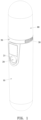
FIG 1 is a perspective view according to a preferred embodiment of the present invention; -
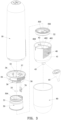
FIG 2 is an exploded view according to the preferred embodiment of the present invention; -
FIG 3 is another exploded view according to the preferred embodiment of the present invention; -
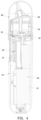
FIG 4 is a cross-sectional view according to the preferred embodiment of the present invention; and -
FIG 5 is a partial cross-sectional view according to the preferred embodiment of the present invention when in use. - Embodiments of the present invention will now be described, by way of example only, with reference to the accompanying drawings.
- Referring to
FIG 1 to FIG 5 , a nasal aspirator capable of effectively preventing backflow according to a preferred embodiment of the present invention comprises acasing 10, acontrol board 20, alower suction nozzle 30, anupper suction nozzle 40, aliquid storage cup 50, and anair pump unit 60. - The
control board 20 is disposed in thecasing 10. Thecontrol board 20 has acontrol button 21. Thecontrol button 21 is exposed to thecasing 10. Thecontrol board 20 may be connected to an external power supply or directly connected to a built-in power supply to supply power to thecontrol board 20. - The
lower suction nozzle 30 is disposed on the upper end of thecasing 10. Thelower suction nozzle 30 has achamber 31 and asuction passageway 32 therein. Thechamber 31 has an opening facing upward. The upper end of thesuction passageway 32 communicates with thechamber 31. Adetection system 70 for detecting a liquid is provided in thechamber 31. Thedetection system 70 is connected to thecontrol board 20. In this embodiment, thelower suction nozzle 30 has afirst boss 33 extending from the bottom of thechamber 31. Thelower suction nozzle 30 further has a connectingtube 34 extending downward from the bottom of thelower suction nozzle 30. Thesuction passageway 32 is formed in thefirst boss 33 and the connectingtube 34. A waterproof andbreathable membrane 35 is fixed on the upper end face of thefirst boss 33. The waterproof andbreathable membrane 35 covers the upper opening of thesuction passageway 32, so as to prevent liquid from flowing into thesuction passageway 32 effectively. The outer wall of the upper end of thelower suction nozzle 30 is recessed with an arc-shaped engaginggroove 36. The bottom of thechamber 31 is formed with a fixinghole 37. The fixinghole 37 extends downward and passes through the bottom of thelower suction nozzle 30. Thedetection system 70 is a probe. The probe is inserted and secured in the fixinghole 37. Thedetection system 70 includes twodetection systems 70 connected to thecontrol board 20. The outer wall of thelower suction nozzle 30 is formed with avent 38 communicating with the inside of thecasing 10 for theair pump unit 60 to exhaust air. - The
upper suction nozzle 40 is mounted to the upper end of thelower suction nozzle 30. Theupper suction nozzle 40 includes amain body shell 41, aninner tube 42, and anouter tube 43. The lower end of themain body shell 41 is hermetically connected to the upper end of thelower suction nozzle 30. Themain body shell 41 has acavity 401 with an opening facing downward. Thecavity 401 communicates with thechamber 31. Theinner tube 42 extends from the top wall of thecavity 401. Theinner tube 42 has afirst passageway 402. Theouter tube 43 extends upward from the upper end face of themain body shell 41. Theouter tube 43 has asecond passageway 403. Thesecond passageway 403 communicates with thefirst passageway 402. In this embodiment, the lower end of themain body shell 41 is sleeved on the upper end of thelower suction nozzle 30. A sealingring 44 is sandwiched between the inner wall of the lower end of themain body shell 41 and the outer wall of the upper end of thelower suction nozzle 30. An engagingportion 404 extends from the inner wall of the lower end of themain body shell 41. The engagingportion 404 is rotatably engaged with the arc-shaped engaginggroove 36. Theouter tube 43 is provided with adetachable suction head 45. Thesuction head 45 has athird passageway 405 therein. Thethird passageway 405 communicates with thesecond passageway 403. Theupper suction nozzle 40 is provided with adetachable cover 80. - The
liquid storage cup 50 is placed in thechamber 31 and thecavity 401. Theliquid storage cup 50 includes acup body 51 and acup cover 52. Thecup body 51 has anaccommodating chamber 501 with an opening facing upward. Thecup cover 52 is disposed on thecup body 51 to cover the opening of theaccommodating chamber 501. Thecup cover 52 is formed with a throughhole 502 and a mountinghole 503. The throughhole 502 communicates with theaccommodating chamber 501 and thecavity 401. The throughhole 502 includes a plurality of spaced through holes to facilitate air intake. Theinner tube 42 passes through the mountinghole 503 and extends into theaccommodating chamber 501. The outer wall of theinner tube 42 is hermetically mated with the inner wall of the mountinghole 503. In this embodiment, the outer bottom surface of thecup body 51 has arecess 504. Asecond boss 505 is formed on the inner bottom surface of thecup body 51. Thefirst boss 33 is located in therecess 504. Theinner tube 42 is close to thesecond boss 505. The lower opening of thefirst passageway 402 faces the upper surface of thesecond boss 505. Thecup cover 52 is coupled to thecup body 51. Apositioning post 506 extends upward from the upper end of thecup body 51. Thecup cover 52 has apositioning hole 507. Thepositioning post 506 is inserted through thepositioning hole 507 and extends out of thecup cover 52. - The
air pump unit 60 is disposed in thecasing 10. The air intake end of theair pump unit 60 communicates with the lower end of thesuction passageway 32. Theair pump unit 60 has amotor 61. Themotor 61 is connected to thecontrol board 20. - The present invention further discloses a control method of the foregoing nasal aspirator capable of effectively preventing backflow. After the
control board 20 is powered on, theair pump unit 60 is turned on, and themotor 61 starts to run. Theair pump unit 60 generates a suction to suck the air in thesuction passageway 32, thechamber 31, thecavity 401, the throughhole 502, theaccommodating chamber 501, thefirst passageway 402 and thesecond passageway 403 in sequence. After the upper end of the upper suction nozzle 40 (i.e. the suction head 45) is placed in a user's nasal cavity, the secretions in the nasal cavity flow through thethird passageway 405, thesecond passageway 403 and thefirst passageway 402 in sequence under the action of the suction and flow into theaccommodating chamber 501 to be collected. When themotor 61 runs, thecontrol board 20 controls thedetection system 70 to detect in real time whether there is a liquid flowing into thechamber 31 of thelower suction nozzle 30 for performing backflow detection. If the liquid is detected, thecontrol board 20 controls themotor 61 to stop running, or, themotor 61 continues to run for collecting the secretions.
Claims (8)
- A nasal aspirator,: the nasal aspirator comprises a casing (10), a lower suction nozzle (30), an upper suction nozzle (40), a liquid storage cup (50) and an air pump unit (60); the lower suction nozzle (30) is disposed on an upper end of the casing (10), the lower suction nozzle (30) has a chamber (31) and a suction passageway (32) therein, the chamber (31) has an opening facing upward, an upper end of the suction passageway (32) communicates with the chamber (31); the upper suction nozzle (40) is mounted to an upper end of the lower suction nozzle (30), the upper suction nozzle (40) includes a main body shell (41), an inner tube (42) and an outer tube (43), a lower end of the main body shell (41) is hermetically connected to the upper end of the lower suction nozzle (30), the main body shell (41) has a cavity (401) with an opening facing downward, the cavity (401) communicates with the chamber (31), the inner tube (42) extends from a top wall of the cavity (401), the inner tube (42) has a first passageway (402), the outer tube (43) extends upward from an upper end face of the main body shell (41), the outer tube (43) has a second passageway (403), the second passageway (403) communicates with the first passageway (402); the liquid storage cup (50) is placed in the chamber (31) and the cavity (401), the liquid storage cup (50) includes a cup body (51) and a cup cover (52), the cup body (51) has an accommodating chamber (501) with an opening facing upward, the cup cover (52) is disposed on the cup body (51) to cover the opening of the accommodating chamber (501), the cup cover (52) is formed with a mounting hole (503), the inner tube (42) passes through the mounting hole (503) and extends into the accommodating chamber (501);the air pump unit (60) is disposed in the casing (10), an air intake end of the air pump unit (60) communicates with a lower end of the suction passageway (32), the air pump unit (60) has a motor (61),wherein the lower suction nozzle (30) has a first boss (33) extending from a bottom of the chamber (31), and the lower suction nozzle (30) further has a connecting tube (34) extending downward from a bottom of the lower suction nozzle (30), and the suction passageway (32) is formed in the first boss (33) and the connecting tube (34),characterized in thatthe cup cover (52) is formed with a through hole (502), the through hole (502) communicates with the accommodating chamber (501) and the cavity (401), an outer wall of the inner tube (42) is hermetically mated with an inner wall of the mounting hole (503);the nasal aspirator comprises a control board (20), the control board (20) is disposed in the casing (10); a detection system (70) for detecting a liquid is provided in the chamber (31), the detection system (70) is connected to the control board (20), and the motor (61) is connected to the control board (20); andthe cup cover (52) is coupled to the cup body (51), a positioning post (506) extends upward from an upper end of the cup body (51), the cup cover (52) has a positioning hole (507), and the positioning post (506) is inserted through the positioning hole (507) and extends out of the cup cover (52).
- The nasal aspirator as claimed in claim 1, wherein the lower end of the main body shell (41) is sleeved on the upper end of the lower suction nozzle (30), and a sealing ring (44) is sandwiched between an inner wall of the lower end of the main body shell (41) and an outer wall of the upper end of the lower suction nozzle (30).
- The nasal aspirator as claimed in claim 1, wherein a waterproof and breathable membrane (35) is fixed on an upper end face of the first boss (33), and the waterproof and breathable membrane (35) covers an upper opening of the suction passageway (32).
- The nasal aspirator as claimed in claim 1, wherein an outer bottom surface of the cup body (51) has a recess (504), a second boss (505) is formed on an inner bottom surface of the cup body (51), and the first boss (33) is located in the recess (504).
- The nasal aspirator as claimed in claim 4, wherein the inner tube (42) is close to the second boss (505), and a lower opening of the first passageway (402) faces an upper surface of the second boss (505).
- The nasal aspirator as claimed in claim 1, wherein a bottom of the chamber (31) is formed with a fixing hole (37), the fixing hole (37) extends downward and passes through a bottom of the lower suction nozzle (30), the detection system (70) is a probe, the probe is inserted and secured in the fixing hole (37), and the detection system (70) includes two detection systems connected to the control board (20).
- The nasal aspirator as claimed in claim 1, wherein the outer tube (43) is provided with a detachable suction head (45), the suction head (45) has a third passageway (405) therein, the third passageway (405) communicates with the second passageway (403), and the upper suction nozzle (40) is provided with a detachable cover (80).
- A control method of the nasal aspirator as claimed in claim 1, wherein after the control board (20) is powered on, the air pump unit (60) is turned on and the motor (61) starts to run, the air pump unit (60) generates a suction to suck air in the suction passageway (32), the chamber (31), the cavity (401), the through hole (502), the accommodating chamber (501), the first passageway (402) and the second passageway (403) in sequence, after an upper end of the upper suction nozzle (40) is placed in a user's nasal cavity, secretions in the nasal cavity flows through the second passageway (403) and the first passageway (402) in sequence under the action of the suction and flows into the accommodating chamber (501) to be collected, when the motor (61) runs, the control board (20) controls the detection system (70) to detect in real time whether there is the liquid flowing into the chamber (31) of the lower suction nozzle (30) for performing backflow detection, if the liquid is detected, the control board (20) controls the motor (61) to stop running, or, the motor (61) continues to run for collecting the secretions.
Priority Applications (3)
| Application Number | Priority Date | Filing Date | Title |
|---|---|---|---|
| EP22176393.1A EP4285951B1 (en) | 2022-05-31 | 2022-05-31 | Nasal aspirator capable of effectively preventing backflow and control method thereof |
| PL22176393.1T PL4285951T3 (en) | 2022-05-31 | 2022-05-31 | Nasal aspirator capable of effectively preventing backflow and control method thereof |
| ES22176393T ES3033012T3 (en) | 2022-05-31 | 2022-05-31 | Nasal aspirator capable of effectively preventing backflow and control method thereof |
Applications Claiming Priority (1)
| Application Number | Priority Date | Filing Date | Title |
|---|---|---|---|
| EP22176393.1A EP4285951B1 (en) | 2022-05-31 | 2022-05-31 | Nasal aspirator capable of effectively preventing backflow and control method thereof |
Publications (3)
| Publication Number | Publication Date |
|---|---|
| EP4285951A1 EP4285951A1 (en) | 2023-12-06 |
| EP4285951B1 true EP4285951B1 (en) | 2025-04-30 |
| EP4285951C0 EP4285951C0 (en) | 2025-04-30 |
Family
ID=81854415
Family Applications (1)
| Application Number | Title | Priority Date | Filing Date |
|---|---|---|---|
| EP22176393.1A Active EP4285951B1 (en) | 2022-05-31 | 2022-05-31 | Nasal aspirator capable of effectively preventing backflow and control method thereof |
Country Status (3)
| Country | Link |
|---|---|
| EP (1) | EP4285951B1 (en) |
| ES (1) | ES3033012T3 (en) |
| PL (1) | PL4285951T3 (en) |
Family Cites Families (3)
| Publication number | Priority date | Publication date | Assignee | Title |
|---|---|---|---|---|
| WO2016002606A1 (en) * | 2014-07-02 | 2016-01-07 | 株式会社村田製作所 | Suction device |
| CN211272649U (en) * | 2019-09-23 | 2020-08-18 | 东莞市振海电子科技有限公司 | Anti-reflux nasal aspirator |
| TWI754566B (en) * | 2021-03-17 | 2022-02-01 | 豪展醫療科技股份有限公司 | Nasal suction device and channel forming method |
-
2022
- 2022-05-31 ES ES22176393T patent/ES3033012T3/en active Active
- 2022-05-31 PL PL22176393.1T patent/PL4285951T3/en unknown
- 2022-05-31 EP EP22176393.1A patent/EP4285951B1/en active Active
Also Published As
| Publication number | Publication date |
|---|---|
| ES3033012T3 (en) | 2025-07-29 |
| PL4285951T3 (en) | 2025-08-18 |
| EP4285951A1 (en) | 2023-12-06 |
| EP4285951C0 (en) | 2025-04-30 |
Similar Documents
| Publication | Publication Date | Title |
|---|---|---|
| US11524105B1 (en) | Nasal aspirator capable of effectively preventing backflow and control method thereof | |
| US7063688B2 (en) | Portable battery operated aspirator | |
| CN216824306U (en) | Automatic nasal discharge collecting device | |
| US7276052B2 (en) | Medical aspirator | |
| CN114515361A (en) | Integrated breast pump | |
| EP4285951A1 (en) | Nasal aspirator capable of effectively preventing backflow and control method thereof | |
| CN210112806U (en) | Detection head module with camera and detection instrument | |
| CN215839335U (en) | Nasal aspirator | |
| CN211272649U (en) | Anti-reflux nasal aspirator | |
| CN110478541A (en) | Counterflow-preventing nose sucking device and its control method | |
| CN219208041U (en) | Multifunctional nasal cavity cleaner | |
| CN221228469U (en) | Blowing and sucking integrated equipment for cleaning pet | |
| CN109010948B (en) | Dedicated sputum aspirator of paediatrics nursing | |
| CN215460700U (en) | Integral wearable breast pump | |
| CN215537440U (en) | Ventilation components, ventilation devices | |
| CN217717139U (en) | High efficiency filter sends out dirt sampling mechanism | |
| CN221498405U (en) | Diving breathing machine with automatic drainage structure on bottom plate | |
| CN215900709U (en) | Facial care device and equipment | |
| CN215537442U (en) | Ventilation components, ventilation devices | |
| CN210750479U (en) | A nasal aspirator with a replaceable tip | |
| CN220002525U (en) | Anti-reflux nose aspirator | |
| CN214356592U (en) | From dive breathing machine of taking cooling function | |
| CN221981269U (en) | A nasal aspirator | |
| CN223641098U (en) | A child's airway clearing device | |
| CN215023061U (en) | A snap-fit assembly structure of a liquid storage bottle of a sputum suction device and a host |
Legal Events
| Date | Code | Title | Description |
|---|---|---|---|
| PUAI | Public reference made under article 153(3) epc to a published international application that has entered the european phase |
Free format text: ORIGINAL CODE: 0009012 |
|
| STAA | Information on the status of an ep patent application or granted ep patent |
Free format text: STATUS: REQUEST FOR EXAMINATION WAS MADE |
|
| 17P | Request for examination filed |
Effective date: 20220906 |
|
| AK | Designated contracting states |
Kind code of ref document: A1 Designated state(s): AL AT BE BG CH CY CZ DE DK EE ES FI FR GB GR HR HU IE IS IT LI LT LU LV MC MK MT NL NO PL PT RO RS SE SI SK SM TR |
|
| GRAP | Despatch of communication of intention to grant a patent |
Free format text: ORIGINAL CODE: EPIDOSNIGR1 |
|
| STAA | Information on the status of an ep patent application or granted ep patent |
Free format text: STATUS: GRANT OF PATENT IS INTENDED |
|
| INTG | Intention to grant announced |
Effective date: 20241206 |
|
| GRAS | Grant fee paid |
Free format text: ORIGINAL CODE: EPIDOSNIGR3 |
|
| GRAA | (expected) grant |
Free format text: ORIGINAL CODE: 0009210 |
|
| STAA | Information on the status of an ep patent application or granted ep patent |
Free format text: STATUS: THE PATENT HAS BEEN GRANTED |
|
| AK | Designated contracting states |
Kind code of ref document: B1 Designated state(s): AL AT BE BG CH CY CZ DE DK EE ES FI FR GB GR HR HU IE IS IT LI LT LU LV MC MK MT NL NO PL PT RO RS SE SI SK SM TR |
|
| REG | Reference to a national code |
Ref country code: CH Ref legal event code: EP Ref country code: GB Ref legal event code: FG4D |
|
| REG | Reference to a national code |
Ref country code: IE Ref legal event code: FG4D |
|
| REG | Reference to a national code |
Ref country code: DE Ref legal event code: R096 Ref document number: 602022013779 Country of ref document: DE |
|
| U01 | Request for unitary effect filed |
Effective date: 20250529 |
|
| U07 | Unitary effect registered |
Designated state(s): AT BE BG DE DK EE FI FR IT LT LU LV MT NL PT RO SE SI Effective date: 20250610 |
|
| U20 | Renewal fee for the european patent with unitary effect paid |
Year of fee payment: 4 Effective date: 20250616 |
|
| REG | Reference to a national code |
Ref country code: ES Ref legal event code: FG2A Ref document number: 3033012 Country of ref document: ES Kind code of ref document: T3 Effective date: 20250729 |
|
| PG25 | Lapsed in a contracting state [announced via postgrant information from national office to epo] |
Ref country code: NO Free format text: LAPSE BECAUSE OF FAILURE TO SUBMIT A TRANSLATION OF THE DESCRIPTION OR TO PAY THE FEE WITHIN THE PRESCRIBED TIME-LIMIT Effective date: 20250730 Ref country code: GR Free format text: LAPSE BECAUSE OF FAILURE TO SUBMIT A TRANSLATION OF THE DESCRIPTION OR TO PAY THE FEE WITHIN THE PRESCRIBED TIME-LIMIT Effective date: 20250731 |
|
| PG25 | Lapsed in a contracting state [announced via postgrant information from national office to epo] |
Ref country code: HR Free format text: LAPSE BECAUSE OF FAILURE TO SUBMIT A TRANSLATION OF THE DESCRIPTION OR TO PAY THE FEE WITHIN THE PRESCRIBED TIME-LIMIT Effective date: 20250430 |
|
| PG25 | Lapsed in a contracting state [announced via postgrant information from national office to epo] |
Ref country code: RS Free format text: LAPSE BECAUSE OF FAILURE TO SUBMIT A TRANSLATION OF THE DESCRIPTION OR TO PAY THE FEE WITHIN THE PRESCRIBED TIME-LIMIT Effective date: 20250731 |
|
| PG25 | Lapsed in a contracting state [announced via postgrant information from national office to epo] |
Ref country code: IS Free format text: LAPSE BECAUSE OF FAILURE TO SUBMIT A TRANSLATION OF THE DESCRIPTION OR TO PAY THE FEE WITHIN THE PRESCRIBED TIME-LIMIT Effective date: 20250830 |
|
| REG | Reference to a national code |
Ref country code: CH Ref legal event code: H13 Free format text: ST27 STATUS EVENT CODE: U-0-0-H10-H13 (AS PROVIDED BY THE NATIONAL OFFICE) Effective date: 20251223 |
|
| PG25 | Lapsed in a contracting state [announced via postgrant information from national office to epo] |
Ref country code: SM Free format text: LAPSE BECAUSE OF FAILURE TO SUBMIT A TRANSLATION OF THE DESCRIPTION OR TO PAY THE FEE WITHIN THE PRESCRIBED TIME-LIMIT Effective date: 20250430 |
|
| PG25 | Lapsed in a contracting state [announced via postgrant information from national office to epo] |
Ref country code: CH Free format text: LAPSE BECAUSE OF NON-PAYMENT OF DUE FEES Effective date: 20250531 |
|
| PG25 | Lapsed in a contracting state [announced via postgrant information from national office to epo] |
Ref country code: CZ Free format text: LAPSE BECAUSE OF FAILURE TO SUBMIT A TRANSLATION OF THE DESCRIPTION OR TO PAY THE FEE WITHIN THE PRESCRIBED TIME-LIMIT Effective date: 20250430 |
|
| PG25 | Lapsed in a contracting state [announced via postgrant information from national office to epo] |
Ref country code: SK Free format text: LAPSE BECAUSE OF FAILURE TO SUBMIT A TRANSLATION OF THE DESCRIPTION OR TO PAY THE FEE WITHIN THE PRESCRIBED TIME-LIMIT Effective date: 20250430 |
|
| PG25 | Lapsed in a contracting state [announced via postgrant information from national office to epo] |
Ref country code: MC Free format text: LAPSE BECAUSE OF FAILURE TO SUBMIT A TRANSLATION OF THE DESCRIPTION OR TO PAY THE FEE WITHIN THE PRESCRIBED TIME-LIMIT Effective date: 20250430 |
|
| PLBE | No opposition filed within time limit |
Free format text: ORIGINAL CODE: 0009261 |
|
| STAA | Information on the status of an ep patent application or granted ep patent |
Free format text: STATUS: NO OPPOSITION FILED WITHIN TIME LIMIT |
|
| REG | Reference to a national code |
Ref country code: CH Ref legal event code: L10 Free format text: ST27 STATUS EVENT CODE: U-0-0-L10-L00 (AS PROVIDED BY THE NATIONAL OFFICE) Effective date: 20260311 |
|
| 26N | No opposition filed |
Effective date: 20260202 |
|
| PGFP | Annual fee paid to national office [announced via postgrant information from national office to epo] |
Ref country code: GB Payment date: 20260318 Year of fee payment: 5 |
|
| PG25 | Lapsed in a contracting state [announced via postgrant information from national office to epo] |
Ref country code: IE Free format text: LAPSE BECAUSE OF NON-PAYMENT OF DUE FEES Effective date: 20250531 |
|
| U20 | Renewal fee for the european patent with unitary effect paid |
Year of fee payment: 5 Effective date: 20260416 |
|
| PGFP | Annual fee paid to national office [announced via postgrant information from national office to epo] |
Ref country code: ES Payment date: 20260618 Year of fee payment: 5 |
|
| PGFP | Annual fee paid to national office [announced via postgrant information from national office to epo] |
Ref country code: PL Payment date: 20260520 Year of fee payment: 5 |
|
| PG25 | Lapsed in a contracting state [announced via postgrant information from national office to epo] |
Ref country code: CY Free format text: LAPSE BECAUSE OF FAILURE TO SUBMIT A TRANSLATION OF THE DESCRIPTION OR TO PAY THE FEE WITHIN THE PRESCRIBED TIME-LIMIT Effective date: 20250430 |