EP4285816A1 - Three-dimensional ventilation image generation method, and controller and apparatus - Google Patents
Three-dimensional ventilation image generation method, and controller and apparatus Download PDFInfo
- Publication number
- EP4285816A1 EP4285816A1 EP21922489.6A EP21922489A EP4285816A1 EP 4285816 A1 EP4285816 A1 EP 4285816A1 EP 21922489 A EP21922489 A EP 21922489A EP 4285816 A1 EP4285816 A1 EP 4285816A1
- Authority
- EP
- European Patent Office
- Prior art keywords
- ventilation
- dimensional
- image
- electrical impedance
- algorithm
- Prior art date
- Legal status (The legal status is an assumption and is not a legal conclusion. Google has not performed a legal analysis and makes no representation as to the accuracy of the status listed.)
- Pending
Links
Images







Classifications
-
- A—HUMAN NECESSITIES
- A61—MEDICAL OR VETERINARY SCIENCE; HYGIENE
- A61B—DIAGNOSIS; SURGERY; IDENTIFICATION
- A61B5/00—Measuring for diagnostic purposes; Identification of persons
- A61B5/05—Detecting, measuring or recording for diagnosis by means of electric currents or magnetic fields; Measuring using microwaves or radio waves
- A61B5/053—Measuring electrical impedance or conductance of a portion of the body
- A61B5/0536—Impedance imaging, e.g. by tomography
-
- A—HUMAN NECESSITIES
- A61—MEDICAL OR VETERINARY SCIENCE; HYGIENE
- A61B—DIAGNOSIS; SURGERY; IDENTIFICATION
- A61B5/00—Measuring for diagnostic purposes; Identification of persons
- A61B5/08—Measuring devices for evaluating the respiratory organs
- A61B5/085—Measuring impedance of respiratory organs or lung elasticity
-
- A—HUMAN NECESSITIES
- A61—MEDICAL OR VETERINARY SCIENCE; HYGIENE
- A61B—DIAGNOSIS; SURGERY; IDENTIFICATION
- A61B5/00—Measuring for diagnostic purposes; Identification of persons
- A61B5/08—Measuring devices for evaluating the respiratory organs
- A61B5/085—Measuring impedance of respiratory organs or lung elasticity
- A61B5/086—Measuring impedance of respiratory organs or lung elasticity by impedance pneumography
-
- A—HUMAN NECESSITIES
- A61—MEDICAL OR VETERINARY SCIENCE; HYGIENE
- A61B—DIAGNOSIS; SURGERY; IDENTIFICATION
- A61B5/00—Measuring for diagnostic purposes; Identification of persons
- A61B5/72—Signal processing specially adapted for physiological signals or for diagnostic purposes
- A61B5/7235—Details of waveform analysis
- A61B5/725—Details of waveform analysis using specific filters therefor, e.g. Kalman or adaptive filters
-
- A—HUMAN NECESSITIES
- A61—MEDICAL OR VETERINARY SCIENCE; HYGIENE
- A61B—DIAGNOSIS; SURGERY; IDENTIFICATION
- A61B5/00—Measuring for diagnostic purposes; Identification of persons
- A61B5/72—Signal processing specially adapted for physiological signals or for diagnostic purposes
- A61B5/7235—Details of waveform analysis
- A61B5/7264—Classification of physiological signals or data, e.g. using neural networks, statistical classifiers, expert systems or fuzzy systems
- A61B5/7267—Classification of physiological signals or data, e.g. using neural networks, statistical classifiers, expert systems or fuzzy systems involving training the classification device
-
- A—HUMAN NECESSITIES
- A61—MEDICAL OR VETERINARY SCIENCE; HYGIENE
- A61B—DIAGNOSIS; SURGERY; IDENTIFICATION
- A61B5/00—Measuring for diagnostic purposes; Identification of persons
- A61B5/72—Signal processing specially adapted for physiological signals or for diagnostic purposes
- A61B5/7271—Specific aspects of physiological measurement analysis
- A61B5/7278—Artificial waveform generation or derivation, e.g. synthesizing signals from measured signals
-
- A—HUMAN NECESSITIES
- A61—MEDICAL OR VETERINARY SCIENCE; HYGIENE
- A61B—DIAGNOSIS; SURGERY; IDENTIFICATION
- A61B2562/00—Details of sensors; Constructional details of sensor housings or probes; Accessories for sensors
- A61B2562/04—Arrangements of multiple sensors of the same type
- A61B2562/046—Arrangements of multiple sensors of the same type in a matrix array
-
- A—HUMAN NECESSITIES
- A61—MEDICAL OR VETERINARY SCIENCE; HYGIENE
- A61B—DIAGNOSIS; SURGERY; IDENTIFICATION
- A61B2576/00—Medical imaging apparatus involving image processing or analysis
- A61B2576/02—Medical imaging apparatus involving image processing or analysis specially adapted for a particular organ or body part
-
- A—HUMAN NECESSITIES
- A61—MEDICAL OR VETERINARY SCIENCE; HYGIENE
- A61B—DIAGNOSIS; SURGERY; IDENTIFICATION
- A61B5/00—Measuring for diagnostic purposes; Identification of persons
- A61B5/0033—Features or image-related aspects of imaging apparatus, e.g. for MRI, optical tomography or impedance tomography apparatus; Arrangements of imaging apparatus in a room
- A61B5/004—Features or image-related aspects of imaging apparatus, e.g. for MRI, optical tomography or impedance tomography apparatus; Arrangements of imaging apparatus in a room adapted for image acquisition of a particular organ or body part
-
- A—HUMAN NECESSITIES
- A61—MEDICAL OR VETERINARY SCIENCE; HYGIENE
- A61B—DIAGNOSIS; SURGERY; IDENTIFICATION
- A61B5/00—Measuring for diagnostic purposes; Identification of persons
- A61B5/02—Detecting, measuring or recording for evaluating the cardiovascular system, e.g. pulse, heart rate, blood pressure or blood flow
- A61B5/026—Measuring blood flow
Definitions
- the present disclosure relates to the field of electrical impedance tomography application, and more particularly relates to a method, controller, and apparatus for three-dimensional ventilation image generation.
- EIT Electrical impedance tomography
- the human body is a volume bioelectric conductor and each tissue or organ therein has a certain impedance.
- the impedance of the corresponding local site inevitably varies relative to other sites, which allows for lesion diagnosis via impedance measurement.
- Conventional techniques can only achieve a two-dimensional ventilation image that reflects change of electrical impedance induced by gas volume variation within some section of a to-be-measured thoracic region of a human body.
- the two-dimensional image can hardly reflect ventilation status of the thoracic cavity of a human body within a certain volume of a three-dimensional space.
- a technical problem to be solved by the disclosure is how to generate a three-dimensional ventilation image that reflects the ventilation status of a human thoracic cavity within various volumes of a three-dimensional space.
- the disclosure provides a method, controller, and apparatus for three-dimensional ventilation image generation.
- the present disclosure provides a three-dimensional ventilation image generation method, comprising: generating a three-dimensional ventilation image by means of a signal extraction algorithm and an image reconstruction algorithm and according to an electrical impedance signal obtained by performing electrical impedance measurement on a target region to be measured, wherein the performing electrical impedance measurement on a target region to be measured is implemented by using an electrode array three-dimensionally distributed on the periphery of the target region to be measured.
- the present disclosure provides a three-dimensional ventilation image generation controller, comprising a memory and a processor, wherein a computer program is stored on the memory and when being executed by the processor, implements the method described above.
- the present disclosure provides a three-dimensional ventilation image generation apparatus, comprising: an electrode array three-dimensionally distributed on an periphery of a target region to be measured, which is configured to perform electrical impedance measurement on the t target region to be measured and transmit a measured electrical impedance to a three-dimensional ventilation image generation controller; and the three-dimensional ventilation image generation controller described above.
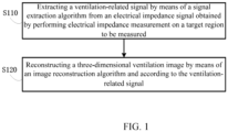
- an embodiment of the present disclosure provides a three-dimensional ventilation image generation method, which are implementable in two manners as illustrated in FIG. 1 and FIG. 2 , respectively.
- the three-dimensional ventilation image generation method comprises steps of:
- the electrical impedance signal comprises a ventilation-related signal and a blood-perfusion-related signal.
- the step of extracting a ventilation-related signal by means of a signal extraction algorithm from the electrical impedance signal obtained by performing electrical impedance measurement on the target region to be measured comprises: extracting the ventilation-related signal using a lowpass filter from the electrical impedance signal obtained by performing electrical impedance measurement on the target region to be measured, wherein the lowpass filter has a cutoff frequency greater than the second harmonic frequency of the ventilation-related signal but lower than the fundamental frequency of the blood-perfusion-related signal.
- the signal extraction algorithm refers to any one of a frequency-domain filtering algorithm, a principal component analysis algorithm, and a neural network algorithm.
- the image reconstruction algorithm refers to a linear differential reconstruction algorithm or a neural-network-based image reconstruction algorithm.
- the three-dimensional ventilation image generation method comprises the following steps:
- step S230 the operation of extracting a time sequence of a ventilation-related pixel from among the time sequences of each pixel in the three-dimensional image is implemented by any one of the frequency-domain filtering algorithm, the principal component analysis algorithm, and the neural network algorithm.
- the image reconstruction algorithm refers to a linear differential reconstruction algorithm or a neural-network-based image reconstruction algorithm.
- embodiments of the present disclosure provide a three-dimensional ventilation image generation method applicable to a human body thoracic cavity based on the first embodiment, in which the three-dimensional ventilation image generation method in this embodiment is implemented in two manners, as illustrated in FIG. 3(a) and FIG. 3(b) , respectively.
- the three-dimensional ventilation image generation method in this embodiment comprises the following steps: first, electrical impedance measurement is performed on a human body thoracic region to be measured; then, a ventilation-related signal is extracted from a measured signal; and finally, a three-dimensional ventilation image is reconstructed. Specific steps of the method are described below: In the first step, electrical impedance measurement is performed on the human body thoracic region to be measured. In the electrical impedance measurement, first an electrode array is required to be fixed surrounding the human body thoracic cavity to be measured. The electrode array comprises a plurality of electrodes distributed in a three-dimensional space. Then, the human body thoracic cavity to be measured is excited via the electrode array and a response produced therefrom is measured, i.e., applying electrical current excitation to the electrodes alternately, and measuring voltage signals produced therefrom on the other electrodes.
- a ventilation-related signal is extracted from the electrical impedance signal obtained by the preceding step.
- the ventilation-related signal is extracted from the measured electrical impedance signal using a filter.
- the filter may refer to a finite pulse response filter or an infinite pulse response filter.
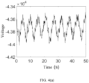
- FIG. 4(a) illustrates a temporal-domain signal of the measurement data, in which the curve represents a voltage signal measured on a specific electrode during excitation. The data obtained during other excitation-measurement processes are derived in a similar manner. It is noted that in the figure, the longitudinal coordinate represents the values directly read from a digital voltage meter, which have not been converted into voltage values yet.
- FIG. 4(a) illustrates a temporal-domain signal of the measurement data, in which the curve represents a voltage signal measured on a specific electrode during excitation. The data obtained during other excitation-measurement processes are derived in a similar manner. It is noted that in the figure, the longitudinal coordinate represents the values directly read from a digital voltage meter, which have not been converted into voltage values yet
- FIG. 4(b) illustrates a frequency-domain signal of the measurement data, wherein the signal illustrated in FIG. 4(b) is derived from the signal in FIG. 4(a) via Fourier transformation.
- the ventilation-related signal and the blood-perfusion-related signal may be differentiated.
- a lowpass filter which may be a finite pulse response lowpass digital filter, may be designed with a cutoff frequency greater than the second harmonic frequency of the ventilation-related signal and lower than the fundamental frequency of the blood-perfusion-related signal.
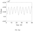
- FIGs. 5(a) and 5(b) illustrate images of the filtered signal, respectively, in which FIG. 5(a) illustrates a temporal-domain signal image and FIG. 5(b) illustrates a frequency-domain signal image.
- the ventilation-related signal is extracted using a principal component analysis (PCA) algorithm.
- PCA principal component analysis
- a template match filtering is performed on the signal u, so as to obtain a ventilation-related signal u V .
- the ventilation-related signal is extracted using the neural-network-based algorithm.
- the neural-network-based algorithm has two phases, i.e., training and predicting.
- training phase a ventilation-related signal extraction network is trained using a supervised or non-supervised method based on training data; and in the predicting phase, the ventilation-related signal in the electrical impedance measurement signals is extracted using the well-trained ventilation-related signal extraction network.
- the three-dimensional ventilation image is reconstructed by means of an image reconstruction algorithm and according to the ventilation-related signal extracted in the second step.
- the three-dimensional ventilation image reflects an electrical impedance change induced by respiration in the human body region to be measured.
- the image reconstruction algorithm refers to a linear differential reconstruction algorithm. An example of reconstructing the three-dimensional ventilation image using the linear differential reconstruction algorithm will be illustrated below.
- the reference moment t ref may be set invariable during the entire image reconstruction process or may be set to dynamically update with the promotion of the image reconstruction process.
- FIG. 6 is a schematic diagram of a three-dimensional ventilation image of a human body thoracic cavity generated by the method above.
- the image reconstruction algorithm refers to a machine-learning-based method.
- the three-dimensional ventilation image generation method comprises the following steps: first, electrical impedance measurement is performed on a human body thoracic region to be measured, then a three-dimensional differential image is reconstructed, and finally, a three-dimensional ventilation image is extracted from the three-dimensional differential image. Specific steps of the method are described below: In the first step, electrical impedance measurement is performed on a human body thoracic region to be measured.
- a three-dimensional differential image is reconstructed by means of an image reconstruction algorithm and according to the electrical impedance signal obtained by the measurement in the preceding step.
- the three-dimensional differential image reflects electrical impedance change in the human body thoracic cavity to be measured, which may be induced by human body ventilation or blood perfusion.
- the image reconstruction algorithm may refer to an image reconstruction algorithm described above.
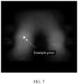
- FIG. 7 illustrates a three-dimensional differential image generated using the data illustrated in FIG. 4 and a linear differential reconstruction algorithm.
- the ventilation image is extracted from the three-dimensional differential image resulting from the preceding step.
- the time sequence of a corresponding pixel on the ventilation image may be obtained.
- FIG. 8(a) and its corresponding spectrogram in FIG. 8(b) illustrate the time sequences of the example pixels of the three-dimensional differential image of the human body thoracic cavity in FIG. 7 .
- FIG. 8(b) enables differentiation between the ventilation-related signal and the blood perfusion-related signal.
- a lowpass filter is designed, which may be a finite pulse response lowpass digital filter with a cutoff frequency greater than the second harmonic frequency of the ventilation-related signal and lower than the fundamental frequency of the blood-perfusion-related signal.
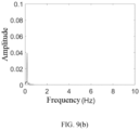
- FIG. 9(a) and the spectrogram in FIG. 9(b) illustrate a temporal-domain signal after the example pixel in FIG. 7 has been filtered.
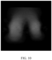
- a three-dimensional ventilation image may be derived, as illustrated in FIG. 10 .
- the ventilation image may be extracted using the principal component analysis algorithm and a neural-network-based algorithm, respectively.
- FIG. 8(a) , FIG. 8(b) , FIG. 9(a) and FIG. 9(b) refers to arbitrary unit.
- the three-dimensional ventilation image generation method applied to a human body thoracic cavity in this embodiment provides a three-dimensional ventilation image, which reflects electrical impedance change induced by human body ventilation in the human body thoracic cavity, thereby reflecting the ventilation status of the human body thoracic cavity within various volumes in the three-dimensional space.
- embodiments of the present disclosure provide a three-dimensional ventilation image generation controller.
- the three-dimensional ventilation image generation controller comprises a memory and a processor, wherein a computer program is stored on the memory, and when being executed by the processor, implements the steps of the method recited in the first embodiment and the second embodiment, respectively.
- embodiments of the present disclosure further provide a three-dimensional ventilation image generation apparatus.
- the three-dimensional ventilation generation apparatus comprises: an electrode array three-dimensionally distributed on the periphery of a target region to be measured, which is configured to perform electrical impedance measurement on the target region to be measured and transmit the measured electrical impedance to a three-dimensional ventilation image generation controller; and the three-dimensional ventilation image generation controller according to Embodiment 3.
- the three-dimensional ventilation image generation apparatus further comprises: an image displaying device configured to display the three-dimensional ventilation image generated by the three-dimensional ventilation image generation controller.
- the three-dimensional ventilation image generation method generates a three-dimensional ventilation image using a signal extraction algorithm and an image reconstruction algorithm based on an electrical impedance signal obtained by performing electrical impedance measurement on the target region to be measured, wherein the performing electrical impedance measurement on the target region to be measured is implemented via an electrode array that is three-dimensionally distributed on the periphery of the target region to be measured, which can provide a three-dimensional ventilation image, thereby ventilation status of the human body thoracic cavity within various volumes in the three-dimensional space is reflected.
Landscapes
- Health & Medical Sciences (AREA)
- Life Sciences & Earth Sciences (AREA)
- Engineering & Computer Science (AREA)
- Physics & Mathematics (AREA)
- Surgery (AREA)
- Public Health (AREA)
- Pathology (AREA)
- Veterinary Medicine (AREA)
- Biomedical Technology (AREA)
- Heart & Thoracic Surgery (AREA)
- Medical Informatics (AREA)
- Molecular Biology (AREA)
- Biophysics (AREA)
- Animal Behavior & Ethology (AREA)
- General Health & Medical Sciences (AREA)
- Artificial Intelligence (AREA)
- Physiology (AREA)
- Pulmonology (AREA)
- Nuclear Medicine, Radiotherapy & Molecular Imaging (AREA)
- Computer Vision & Pattern Recognition (AREA)
- Psychiatry (AREA)
- Signal Processing (AREA)
- Radiology & Medical Imaging (AREA)
- Evolutionary Computation (AREA)
- Fuzzy Systems (AREA)
- Mathematical Physics (AREA)
- Measurement And Recording Of Electrical Phenomena And Electrical Characteristics Of The Living Body (AREA)
Abstract
Description
- The present disclosure claims the priority of Chinese Patent Application No.
CN202110111098.8 filed on January 26, 2021 - The present disclosure relates to the field of electrical impedance tomography application, and more particularly relates to a method, controller, and apparatus for three-dimensional ventilation image generation.
- Electrical impedance tomography (EIT) is a non-invasive technique that aims to reconstructing image of an in vivo tissue by reflecting electrical resistivity distribution within a human body or other living body. The human body is a volume bioelectric conductor and each tissue or organ therein has a certain impedance. When a local organ of the human body has a lesion, the impedance of the corresponding local site inevitably varies relative to other sites, which allows for lesion diagnosis via impedance measurement.
- Conventional techniques can only achieve a two-dimensional ventilation image that reflects change of electrical impedance induced by gas volume variation within some section of a to-be-measured thoracic region of a human body. However, the two-dimensional image can hardly reflect ventilation status of the thoracic cavity of a human body within a certain volume of a three-dimensional space.
- Therefore, a method, controller, and apparatus for three-dimensional ventilation image generation are needed.
- A technical problem to be solved by the disclosure is how to generate a three-dimensional ventilation image that reflects the ventilation status of a human thoracic cavity within various volumes of a three-dimensional space.
- To overcome the above problems, the disclosure provides a method, controller, and apparatus for three-dimensional ventilation image generation.
- In a first aspect, the present disclosure provides a three-dimensional ventilation image generation method, comprising: generating a three-dimensional ventilation image by means of a signal extraction algorithm and an image reconstruction algorithm and according to an electrical impedance signal obtained by performing electrical impedance measurement on a target region to be measured, wherein the performing electrical impedance measurement on a target region to be measured is implemented by using an electrode array three-dimensionally distributed on the periphery of the target region to be measured.
- In a second aspect, the present disclosure provides a three-dimensional ventilation image generation controller, comprising a memory and a processor, wherein a computer program is stored on the memory and when being executed by the processor, implements the method described above.
- In a third aspect, the present disclosure provides a three-dimensional ventilation image generation apparatus, comprising: an electrode array three-dimensionally distributed on an periphery of a target region to be measured, which is configured to perform electrical impedance measurement on the t target region to be measured and transmit a measured electrical impedance to a three-dimensional ventilation image generation controller; and the three-dimensional ventilation image generation controller described above.
- Other features and advantages of the present disclosure will be explained in the description below, which partially become apparent from the description or partially become understood via implementing the disclosure. The objectives and other benefits of the disclosure may be realized and derived via specific structures illustrated in the description, claims and accompanying drawings.
- The accompanying drawings are provided for further understanding the disclosure and constitute a part of the specification, which, together with the embodiments of the present disclosure, may be used for explaining the disclosure, but do not constitute limitation to the disclosure. In the accompanying drawings:
-
FIG. 1 is a flow diagram of a three-dimensional ventilation image generation method according to a first embodiment of the disclosure; -
FIG. 2 is another flow diagram of the three-dimensional ventilation image generation method according to the first embodiment of the disclosure; -
FIG. 3(a) is a flow diagram of a three-dimensional ventilation image generation method according to a second embodiment of the disclosure; -
FIG. 3(b) is another flow diagram of the three-dimensional ventilation image generation method according to the second embodiment of the disclosure; -
FIG. 4(a) is a temporal-domain signal schematic diagram of human body thoracic cavity measurement data according to the second embodiment of the disclosure; -
FIG. 4(b) is a frequency-domain signal schematic diagram of the human body thoracic cavity measurement data according to the second embodiment of the disclosure; -
FIG. 5(a) is a temporal-domain signal schematic diagram of a ventilation-related signal after the human body thoracic cavity measurement data have been filtered according to the second embodiment of the disclosure; -
FIG. 5(b) is a frequency-domain signal schematic diagram of a ventilation-related signal after the human body thoracic cavity measurement data have been filtered according to the second embodiment of the disclosure; -
FIG. 6 is a schematic diagram of a three-dimensional ventilation image of a human body thoracic cavity generated using the three-dimensional ventilation image generation method illustrated inFIG. 3(a) according to the second embodiment of the present disclosure; -
FIG. 7 is a schematic diagram of a three-dimensional differential image of a human body thoracic cavity generated using the three-dimensional ventilation image generation method illustrated inFIG. 3(b) according to the second embodiment of the present disclosure; -
FIG. 8(a) is a temporal-domain signal schematic diagram of an example pixel inFIG. 7 ; -
FIG. 8(b) is a frequency-domain signal schematic diagram of an example pixel inFIG. 7 ; -
FIG. 9(a) is a temporal-domain signal schematic diagram of a ventilation-related signal after the example pixel inFIG. 7 has been subjected to data filtering; -
FIG. 9(b) is a frequency-domain signal schematic diagram of a ventilation-related signal after the example pixel inFIG. 7 has been subjected to data filtering; -
FIG. 10 is a schematic diagram of a three-dimensional ventilation image of a human body thoracic cavity generated using the three-dimensional ventilation image generation method illustrated inFIG. 3(b) according to the second embodiment of the present disclosure. - Hereinafter, the embodiments of the disclosure will be elaborated through embodiments with reference to the accompanying drawings such that how the disclosure uses technical means to solve technical problems and how the technical effects are achieved will become sufficiently understood and implementable. It is noted that without conflicts, various embodiments and respective features in the embodiments may be combined with each other, and a technical solution resulting from such combination falls within the protection scope of the disclosure.
- To solve the above technical problems in the existing technologies, an embodiment of the present disclosure provides a three-dimensional ventilation image generation method, which are implementable in two manners as illustrated in
FIG. 1 andFIG. 2 , respectively. - Referring to
FIG. 1 , the three-dimensional ventilation image generation method according to this embodiment comprises steps of: - S 110: a ventilation-related signal is extracted by means of a signal extraction algorithm from an electrical impedance signal obtained by performing electrical impedance measurement on a target region to be measured. Herein the operation of performing electrical impedance measurement on said target region is implemented by using an electrode array three-dimensionally distributed on the periphery of the target region to be measured, and the electrode array may be a plurality of impedance straps or an electrode vest where the electrodes are three-dimensionally distributed.
- Step S120: a three-dimensional ventilation image is reconstructed by means of an image reconstruction algorithm and according to the ventilation-related signal.
- In an embodiment, the electrical impedance signal comprises a ventilation-related signal and a blood-perfusion-related signal. The step of extracting a ventilation-related signal by means of a signal extraction algorithm from the electrical impedance signal obtained by performing electrical impedance measurement on the target region to be measured comprises: extracting the ventilation-related signal using a lowpass filter from the electrical impedance signal obtained by performing electrical impedance measurement on the target region to be measured, wherein the lowpass filter has a cutoff frequency greater than the second harmonic frequency of the ventilation-related signal but lower than the fundamental frequency of the blood-perfusion-related signal.
- In step S110, the signal extraction algorithm refers to any one of a frequency-domain filtering algorithm, a principal component analysis algorithm, and a neural network algorithm.
- In step S120, the image reconstruction algorithm refers to a linear differential reconstruction algorithm or a neural-network-based image reconstruction algorithm.
- Referring to
FIG. 2 , the three-dimensional ventilation image generation method according to this embodiment comprises the following steps: - S210: a three-dimensional image is reconstructed by means of an image reconstruction algorithm and according to an electrical impedance signal obtained by performing electrical impedance measurement on a target region to be measured. Herein, the operation of performing electrical impedance measurement to the target region to be measured is implemented by an electrode array that is three-dimensionally distributed on the periphery of the target region to be measured.
- S220: a time sequence of each pixel in the three-dimensional image is listed according to three-dimensional image data at a plurality of moments. Herein, the time sequence of each pixel is comprised of values of each pixel at the different moments.
- S230: a time sequence of a ventilation-related pixel is extracted from among the time sequences of each pixel in the three-dimensional image.
- S240: a three-dimensional ventilation image is constructed according to the time sequence of the ventilation-related pixel.
- In step S230, the operation of extracting a time sequence of a ventilation-related pixel from among the time sequences of each pixel in the three-dimensional image is implemented by any one of the frequency-domain filtering algorithm, the principal component analysis algorithm, and the neural network algorithm.
- In step S210, the image reconstruction algorithm refers to a linear differential reconstruction algorithm or a neural-network-based image reconstruction algorithm.
- To solve the above technical problems in the existing technologies, embodiments of the present disclosure provide a three-dimensional ventilation image generation method applicable to a human body thoracic cavity based on the first embodiment, in which the three-dimensional ventilation image generation method in this embodiment is implemented in two manners, as illustrated in
FIG. 3(a) andFIG. 3(b) , respectively. - As illustrated in
FIG. 3(a) , the three-dimensional ventilation image generation method in this embodiment comprises the following steps: first, electrical impedance measurement is performed on a human body thoracic region to be measured; then, a ventilation-related signal is extracted from a measured signal; and finally, a three-dimensional ventilation image is reconstructed. Specific steps of the method are described below:
In the first step, electrical impedance measurement is performed on the human body thoracic region to be measured. In the electrical impedance measurement, first an electrode array is required to be fixed surrounding the human body thoracic cavity to be measured. The electrode array comprises a plurality of electrodes distributed in a three-dimensional space. Then, the human body thoracic cavity to be measured is excited via the electrode array and a response produced therefrom is measured, i.e., applying electrical current excitation to the electrodes alternately, and measuring voltage signals produced therefrom on the other electrodes. - In the second step, a ventilation-related signal is extracted from the electrical impedance signal obtained by the preceding step. In an embodiment of this step, the ventilation-related signal is extracted from the measured electrical impedance signal using a filter. The filter may refer to a finite pulse response filter or an infinite pulse response filter. Embodiments of measuring the human body thoracic cavity will be illustrated below.
FIG. 4(a) illustrates a temporal-domain signal of the measurement data, in which the curve represents a voltage signal measured on a specific electrode during excitation. The data obtained during other excitation-measurement processes are derived in a similar manner. It is noted that in the figure, the longitudinal coordinate represents the values directly read from a digital voltage meter, which have not been converted into voltage values yet.FIG. 4(b) illustrates a frequency-domain signal of the measurement data, wherein the signal illustrated inFIG. 4(b) is derived from the signal inFIG. 4(a) via Fourier transformation. InFIG. 4(b) , the ventilation-related signal and the blood-perfusion-related signal may be differentiated. To extract the ventilation-related signal, a lowpass filter, which may be a finite pulse response lowpass digital filter, may be designed with a cutoff frequency greater than the second harmonic frequency of the ventilation-related signal and lower than the fundamental frequency of the blood-perfusion-related signal.FIGs. 5(a) and5(b) illustrate images of the filtered signal, respectively, in whichFIG. 5(a) illustrates a temporal-domain signal image andFIG. 5(b) illustrates a frequency-domain signal image. - In another embodiment of this step, the ventilation-related signal is extracted using a principal component analysis (PCA) algorithm. Specifically, assuming a measurement signal is denoted as u, with a size of Nt × Nc, where Nt denotes the number of sample points and Nc denotes the characteristic number (which refers to the number of measurement paths herein). The principal components {p 1, p 2, ... , p N
c } of the signal are obtained by using a principal component analysis, where the size of p i (i = 1,2, ... , Nc ) is Nt × land their corresponding characteristic values decrease sequentially. By using a first and early plurality of principal components (e.g., p1 and p 2) as a template, a template match filtering is performed on the signal u, so as to obtain a ventilation-related signal u V . - In a further embodiment of this step, the ventilation-related signal is extracted using the neural-network-based algorithm. Specifically, the neural-network-based algorithm has two phases, i.e., training and predicting. In the training phase, a ventilation-related signal extraction network is trained using a supervised or non-supervised method based on training data; and in the predicting phase, the ventilation-related signal in the electrical impedance measurement signals is extracted using the well-trained ventilation-related signal extraction network.
- In the third step, the three-dimensional ventilation image is reconstructed by means of an image reconstruction algorithm and according to the ventilation-related signal extracted in the second step. The three-dimensional ventilation image reflects an electrical impedance change induced by respiration in the human body region to be measured. In an embodiment of this step, the image reconstruction algorithm refers to a linear differential reconstruction algorithm. An example of reconstructing the three-dimensional ventilation image using the linear differential reconstruction algorithm will be illustrated below.
- Assuming that the temporal-domain form of the ventilation-related signal extracted in the second step is u(t), where t denotes a temporal variable, the EIT differential reconstruction may be expressed as a least square problem:


- Letting D = (J T · J + α R T · R)-1 · J T , then the equation may be rewritten as:

-
FIG. 6 is a schematic diagram of a three-dimensional ventilation image of a human body thoracic cavity generated by the method above. - In another embodiment of this step, the image reconstruction algorithm refers to a machine-learning-based method. The EIT differential imaging may be expressed as:


 :
:

- In addition to the image reconstruction algorithm in the above embodiments, various linear or nonlinear, iterative or non iterative, random or deterministic image reconstruction algorithms can also be used in this step.
- As illustrated in
FIG. 3(b) , the three-dimensional ventilation image generation method according to this embodiment comprises the following steps: first, electrical impedance measurement is performed on a human body thoracic region to be measured, then a three-dimensional differential image is reconstructed, and finally, a three-dimensional ventilation image is extracted from the three-dimensional differential image. Specific steps of the method are described below:
In the first step, electrical impedance measurement is performed on a human body thoracic region to be measured. - In the second step, a three-dimensional differential image is reconstructed by means of an image reconstruction algorithm and according to the electrical impedance signal obtained by the measurement in the preceding step. The three-dimensional differential image reflects electrical impedance change in the human body thoracic cavity to be measured, which may be induced by human body ventilation or blood perfusion. The image reconstruction algorithm may refer to an image reconstruction algorithm described above.
FIG. 7 illustrates a three-dimensional differential image generated using the data illustrated inFIG. 4 and a linear differential reconstruction algorithm. - In the third step, the ventilation image is extracted from the three-dimensional differential image resulting from the preceding step. In an embodiment of this step, a ventilation image is extracted from the three-dimensional differential image using a filter. Supposing the three-dimensional differential images at N moments may be arrayed into a matrix A = { a 1, a 2, ... , a M } T , where a i (i = 1,2, ..., M) denotes a column vector composed of the values of pixel i at N moments, and M denotes the total number of the pixels in the three-dimensional image. By performing a lowpass filtering on the time sequence a i (i = 1,2, ..., M) of each pixel i, the time sequence of a corresponding pixel on the ventilation image may be obtained. Specifically, given the filter function f (·), then the ventilation image is AV = { f(a 1), f ( a 2 ), ... , f ( a M )} T.
-
FIG. 8(a) and its corresponding spectrogram inFIG. 8(b) illustrate the time sequences of the example pixels of the three-dimensional differential image of the human body thoracic cavity inFIG. 7 .FIG. 8(b) enables differentiation between the ventilation-related signal and the blood perfusion-related signal. In order to extract the ventilation-related signal, a lowpass filter is designed, which may be a finite pulse response lowpass digital filter with a cutoff frequency greater than the second harmonic frequency of the ventilation-related signal and lower than the fundamental frequency of the blood-perfusion-related signal. -
FIG. 9(a) and the spectrogram inFIG. 9(b) illustrate a temporal-domain signal after the example pixel inFIG. 7 has been filtered. After each pixel in the three-dimensional differential image has been subjected to the lowpass filter, a three-dimensional ventilation image may be derived, as illustrated inFIG. 10 . In two further embodiments of this step, the ventilation image may be extracted using the principal component analysis algorithm and a neural-network-based algorithm, respectively. - It is noted that A.U. in
FIG. 8(a) ,FIG. 8(b) ,FIG. 9(a) andFIG. 9(b) refers to arbitrary unit. - The three-dimensional ventilation image generation method applied to a human body thoracic cavity in this embodiment provides a three-dimensional ventilation image, which reflects electrical impedance change induced by human body ventilation in the human body thoracic cavity, thereby reflecting the ventilation status of the human body thoracic cavity within various volumes in the three-dimensional space.
- To solve the technical problems in the existing technologies, embodiments of the present disclosure provide a three-dimensional ventilation image generation controller.
- The three-dimensional ventilation image generation controller according to this embodiment comprises a memory and a processor, wherein a computer program is stored on the memory, and when being executed by the processor, implements the steps of the method recited in the first embodiment and the second embodiment, respectively.
- To solve the technical problems in the existing technologies, embodiments of the present disclosure further provide a three-dimensional ventilation image generation apparatus.
- The three-dimensional ventilation generation apparatus according to this embodiment comprises: an electrode array three-dimensionally distributed on the periphery of a target region to be measured, which is configured to perform electrical impedance measurement on the target region to be measured and transmit the measured electrical impedance to a three-dimensional ventilation image generation controller; and the three-dimensional ventilation image generation controller according to Embodiment 3.
- The three-dimensional ventilation image generation apparatus according to this embodiment further comprises: an image displaying device configured to display the three-dimensional ventilation image generated by the three-dimensional ventilation image generation controller.
- Compared with the existing technologies, one or more embodiments of the above solution may have the following advantages or beneficial effects: the three-dimensional ventilation image generation method according to the present disclosure generates a three-dimensional ventilation image using a signal extraction algorithm and an image reconstruction algorithm based on an electrical impedance signal obtained by performing electrical impedance measurement on the target region to be measured, wherein the performing electrical impedance measurement on the target region to be measured is implemented via an electrode array that is three-dimensionally distributed on the periphery of the target region to be measured, which can provide a three-dimensional ventilation image, thereby ventilation status of the human body thoracic cavity within various volumes in the three-dimensional space is reflected.
- Although the embodiments of the disclosure have been disclosed above, the contents are only embodiments for facilitating the understanding of the disclosure, and are not intended for limiting the disclosure. Any person skilled in the art to which this disclosure belongs may make any modifications and variations to the form and details of the embodiments without departing from the spirits and scope of the disclosure, while the protection scope of the disclosure is governed by the scope limited in the appended claims.
Claims (10)
- A three-dimensional ventilation image generation method, comprising steps of:
generating a three-dimensional ventilation image by means of a signal extraction algorithm and an image reconstruction algorithm and according to an electrical impedance signal obtained by performing electrical impedance measurement on a target region to be measured, wherein the performing electrical impedance measurement on a target region to be measured is implemented by using an electrode array that is three-dimensionally distributed on the periphery of said target region to be measured. - The method according to claim 1, wherein the generating a three-dimensional ventilation image by means of a signal extraction algorithm and an image reconstruction algorithm and according to an electrical impedance signal obtained by performing electrical impedance measurement on a target region to be measured comprises:extracting a ventilation-related signal by means of the signal extraction algorithm from the electrical impedance signal obtained by performing electrical impedance measurement on the target region to be measured;reconstructing the three-dimensional ventilation image by means of an image reconstruction algorithm and according to the ventilation-related signal.
- The method according to claim 2, wherein the electrical impedance signal comprises the ventilation-related signal and a blood-perfusion-related signal, and the extracting a ventilation-related signal by means of a signal extraction algorithm from the electrical impedance signal obtained by performing electrical impedance measurement on a target region to be measured comprises:
extracting the ventilation-related signal using a lowpass filter from the electrical impedance signal obtained by performing electrical impedance measurement on the target region to be measured, wherein the lowpass filter has a cutoff frequency greater than the second harmonic frequency of the ventilation-related signal but lower than the fundamental frequency of the blood-perfusion-related signal. - The method according to claim 1, wherein the generating a three-dimensional ventilation image by means of a signal extraction algorithm and an image reconstruction algorithm and according to an electrical impedance signal obtained by performing electrical impedance measurement on a target region to be measured comprises:reconstructing a three-dimensional image by means of an image reconstruction algorithm and according to the electrical impedance signal obtained by performing electrical impedance measurement on the target region to be measured;extracting the three-dimensional ventilation image from the three-dimensional image by means of the signal extraction algorithm.
- The method according to claim 4, wherein the extracting the three-dimensional ventilation image from the three-dimensional image by means of the signal extraction algorithm comprises:listing a time sequence of each pixel in the three-dimensional image according to three-dimensional image data at a plurality of moments, wherein the time sequence of each pixel is comprised of values of each pixel at different moments;extracting a time sequence of a ventilation-related pixel from among the time sequences of each pixel in the three-dimensional image;constructing the three-dimensional ventilation image according to the time sequence of the ventilation-related pixel.
- The method according to claim 5, wherein the extracting a time sequence of a ventilation-related pixel from among the time sequences of each pixel in the three-dimensional image is implemented by any one of a frequency-domain filtering algorithm, a principal component analysis algorithm, and a neural network algorithm.
- The method according to claim 2 or 4, wherein the signal extraction algorithm refers to any one of a frequency-domain filtering algorithm, a principal component analysis algorithm, and a neural network algorithm.
- The method according to claim 2 or 4, wherein the image reconstruction algorithm refers to a linear differential reconstruction algorithm or a neural-network-based image reconstruction algorithm.
- A three-dimensional ventilation image generation controller, comprising a memory and a processor, wherein a computer program is store on the memory and, when being executed by the processor, implements steps of the method according to any one of claims 1 to 8.
- A three-dimensional ventilation image generation apparatus, comprising:an electrode array three-dimensionally distributed on an periphery of a target region to be measured, which is configured to perform electrical impedance measurement on the target region to be measured and transmit a measured electrical impedance to a three-dimensional ventilation image generation controller; andthe three-dimensional ventilation image generation controller according to claim 9.
Applications Claiming Priority (2)
| Application Number | Priority Date | Filing Date | Title |
|---|---|---|---|
| CN202110111098.8A CN113749636B (en) | 2021-01-26 | 2021-01-26 | Three-dimensional ventilation image generation method, controller and device |
| PCT/CN2021/132763 WO2022160899A1 (en) | 2021-01-26 | 2021-11-24 | Three-dimensional ventilation image generation method, and controller and apparatus |
Publications (2)
| Publication Number | Publication Date |
|---|---|
| EP4285816A1 true EP4285816A1 (en) | 2023-12-06 |
| EP4285816A4 EP4285816A4 (en) | 2024-12-11 |
Family
ID=78786469
Family Applications (1)
| Application Number | Title | Priority Date | Filing Date |
|---|---|---|---|
| EP21922489.6A Pending EP4285816A4 (en) | 2021-01-26 | 2021-11-24 | Three-dimensional ventilation image generation method, and controller and apparatus |
Country Status (5)
| Country | Link |
|---|---|
| US (1) | US12575754B2 (en) |
| EP (1) | EP4285816A4 (en) |
| JP (1) | JP7713188B2 (en) |
| CN (1) | CN113749636B (en) |
| WO (1) | WO2022160899A1 (en) |
Families Citing this family (1)
| Publication number | Priority date | Publication date | Assignee | Title |
|---|---|---|---|---|
| CN115153500A (en) * | 2022-07-04 | 2022-10-11 | 北京华睿博视医学影像技术有限公司 | Method and apparatus for presenting the relationship between respiratory impedance and respiratory impedance rate of change |
Family Cites Families (11)
| Publication number | Priority date | Publication date | Assignee | Title |
|---|---|---|---|---|
| SE9803862L (en) * | 1998-11-11 | 2000-03-20 | Siemens Elema Ab | Electrical impedance tomography system |
| JP5672147B2 (en) * | 2011-05-24 | 2015-02-18 | コニカミノルタ株式会社 | Chest diagnosis support information generation system |
| WO2014091977A1 (en) * | 2012-12-12 | 2014-06-19 | コニカミノルタ株式会社 | Image-processing device and program |
| KR101812587B1 (en) | 2016-11-18 | 2018-01-30 | 주식회사 바이랩 | Method and apparatus for video monitoring of patient, and video monitoring system |
| DE102017006107A1 (en) * | 2017-06-28 | 2019-01-03 | Drägerwerk AG & Co. KGaA | Device and method for processing and visualizing data obtained by means of an electro-impedance tomography device (EIT) with regard to a perfusion state of the heart and lungs |
| US11412946B2 (en) * | 2017-11-14 | 2022-08-16 | Timpel Medical B.V. | Electrical impedance tomography device and system having a multi-dimensional electrode arrangement |
| WO2020007991A1 (en) * | 2018-07-04 | 2020-01-09 | Navix International Limited | System and method for conductivity-based imaging |
| CN109864712B (en) * | 2019-04-02 | 2024-07-05 | 北京华睿博视医学影像技术有限公司 | Electrical impedance imaging device and method |
| CN111053556A (en) * | 2019-12-26 | 2020-04-24 | 北京华睿博视医学影像技术有限公司 | Electrical Impedance Imaging Method and Device Based on Supervised Descent Method |
| CN111067521B (en) * | 2019-12-31 | 2021-10-01 | 北京华睿博视医学影像技术有限公司 | Method and device for generating 3D blood perfusion image based on electrical impedance imaging |
| CN112057073A (en) * | 2020-09-08 | 2020-12-11 | 北京华睿博视医学影像技术有限公司 | Method, equipment and system for synchronously generating breathing and blood perfusion images |
-
2021
- 2021-01-26 CN CN202110111098.8A patent/CN113749636B/en active Active
- 2021-11-24 US US18/268,891 patent/US12575754B2/en active Active
- 2021-11-24 EP EP21922489.6A patent/EP4285816A4/en active Pending
- 2021-11-24 WO PCT/CN2021/132763 patent/WO2022160899A1/en not_active Ceased
- 2021-11-24 JP JP2023544419A patent/JP7713188B2/en active Active
Also Published As
| Publication number | Publication date |
|---|---|
| US20240057887A1 (en) | 2024-02-22 |
| EP4285816A4 (en) | 2024-12-11 |
| CN113749636A (en) | 2021-12-07 |
| JP7713188B2 (en) | 2025-07-25 |
| CN113749636B (en) | 2022-06-24 |
| WO2022160899A1 (en) | 2022-08-04 |
| US12575754B2 (en) | 2026-03-17 |
| JP2024505852A (en) | 2024-02-08 |
Similar Documents
| Publication | Publication Date | Title |
|---|---|---|
| CN111616708B (en) | An image reconstruction method for accurately identifying intracranial lesion areas in stroke | |
| KR102824526B1 (en) | Systems and methods for processing image slices from three-dimensional images | |
| Dusek et al. | Electrical impedance tomography methods and algorithms processed with a GPU | |
| EP3200159A1 (en) | High definition coloring of heart chambers | |
| EP4085828A1 (en) | Electrical impedance tomography based method and device for generating three-dimensional blood perfusion image | |
| JP6523730B2 (en) | Magnetic resonance imaging system | |
| CN111417342A (en) | Brain network activity estimation system, brain network activity estimation method, brain network activity estimation program, and learned brain activity estimation model | |
| JP7440985B2 (en) | Electrical impedance imaging methods, systems, storage media and electronic equipment | |
| EP4201308A1 (en) | Excitation response measurement method, electrical impedance tomography method, and storage medium | |
| CN117476153A (en) | Medical imaging device, interface information display method and device thereof, and storage medium | |
| CN112057073A (en) | Method, equipment and system for synchronously generating breathing and blood perfusion images | |
| JP5178909B2 (en) | In vivo potential estimation apparatus and method using impedance-switching multipoint surface electrode | |
| US12575754B2 (en) | Three-dimensional ventilation image generation method, and controller and apparatus | |
| US20150342496A1 (en) | Method and apparatus for generating medical image data records | |
| CN106821380A (en) | Biomedical electrical impedance imaging method and device based on multiplicative regularization | |
| Sermesant et al. | Progress towards an electromechanical model of the heart for cardiac image analysis | |
| Meeson et al. | The dependence of EIT images on the assumed initial conductivity distribution: a study of pelvic imaging | |
| JPH0399630A (en) | Equivalent dipole measuring apparatus and equivalent dipole estimating method | |
| US20040034309A1 (en) | Method and system of defining a model of one or more organs | |
| Jiang et al. | Optimization of the electrode positions of multichannel ECG for the reconstruction of ischemic areas by solving the inverse electrocardiographic problem | |
| US20190246915A1 (en) | System and method for reconstructing a physiological signal of an artery/tissue/vein dynamic system of an organ in a surface space | |
| Adler et al. | GREIT: towards a consensus EIT algorithm for lung images | |
| CN109785308A (en) | A kind of method, apparatus, equipment and storage medium that heart stroke solves | |
| Pan et al. | Targeted-ROI imaging in electron paramagnetic resonance imaging | |
| JP2799672B2 (en) | Brain cortical activity tracking device |
Legal Events
| Date | Code | Title | Description |
|---|---|---|---|
| STAA | Information on the status of an ep patent application or granted ep patent |
Free format text: STATUS: THE INTERNATIONAL PUBLICATION HAS BEEN MADE |
|
| PUAI | Public reference made under article 153(3) epc to a published international application that has entered the european phase |
Free format text: ORIGINAL CODE: 0009012 |
|
| STAA | Information on the status of an ep patent application or granted ep patent |
Free format text: STATUS: REQUEST FOR EXAMINATION WAS MADE |
|
| 17P | Request for examination filed |
Effective date: 20230719 |
|
| AK | Designated contracting states |
Kind code of ref document: A1 Designated state(s): AL AT BE BG CH CY CZ DE DK EE ES FI FR GB GR HR HU IE IS IT LI LT LU LV MC MK MT NL NO PL PT RO RS SE SI SK SM TR |
|
| DAV | Request for validation of the european patent (deleted) | ||
| DAX | Request for extension of the european patent (deleted) | ||
| RAP1 | Party data changed (applicant data changed or rights of an application transferred) |
Owner name: TSINGHUA UNIVERSITY Owner name: BEIJING HUARUI BOSHI MEDICAL IMAGINGTECHNOLOGY CO., LTD. |
|
| A4 | Supplementary search report drawn up and despatched |
Effective date: 20241112 |
|
| RIC1 | Information provided on ipc code assigned before grant |
Ipc: A61B 5/00 20060101ALI20241107BHEP Ipc: A61B 5/0536 20210101AFI20241107BHEP |
|
| STAA | Information on the status of an ep patent application or granted ep patent |
Free format text: STATUS: EXAMINATION IS IN PROGRESS |
|
| 17Q | First examination report despatched |
Effective date: 20251031 |