EP4285796A1 - Container cover of an electric household appliance, assembling method, and household appliance - Google Patents
Container cover of an electric household appliance, assembling method, and household appliance Download PDFInfo
- Publication number
- EP4285796A1 EP4285796A1 EP22175976.4A EP22175976A EP4285796A1 EP 4285796 A1 EP4285796 A1 EP 4285796A1 EP 22175976 A EP22175976 A EP 22175976A EP 4285796 A1 EP4285796 A1 EP 4285796A1
- Authority
- EP
- European Patent Office
- Prior art keywords
- cover
- gear box
- gear
- household appliance
- container
- Prior art date
- Legal status (The legal status is an assumption and is not a legal conclusion. Google has not performed a legal analysis and makes no representation as to the accuracy of the status listed.)
- Granted
Links
Images

Classifications
-
- A—HUMAN NECESSITIES
- A47—FURNITURE; DOMESTIC ARTICLES OR APPLIANCES; COFFEE MILLS; SPICE MILLS; SUCTION CLEANERS IN GENERAL
- A47J—KITCHEN EQUIPMENT; COFFEE MILLS; SPICE MILLS; APPARATUS FOR MAKING BEVERAGES
- A47J43/00—Implements for preparing or holding food, not provided for in other groups of this subclass
- A47J43/04—Machines for domestic use not covered elsewhere, e.g. for grinding, mixing, stirring, kneading, emulsifying, whipping or beating foodstuffs, e.g. power-driven
- A47J43/07—Parts or details, e.g. mixing tools, whipping tools
- A47J43/08—Driving mechanisms
- A47J43/082—Driving mechanisms for machines with tools driven from the upper side
-
- A—HUMAN NECESSITIES
- A47—FURNITURE; DOMESTIC ARTICLES OR APPLIANCES; COFFEE MILLS; SPICE MILLS; SUCTION CLEANERS IN GENERAL
- A47J—KITCHEN EQUIPMENT; COFFEE MILLS; SPICE MILLS; APPARATUS FOR MAKING BEVERAGES
- A47J43/00—Implements for preparing or holding food, not provided for in other groups of this subclass
- A47J43/04—Machines for domestic use not covered elsewhere, e.g. for grinding, mixing, stirring, kneading, emulsifying, whipping or beating foodstuffs, e.g. power-driven
- A47J43/044—Machines for domestic use not covered elsewhere, e.g. for grinding, mixing, stirring, kneading, emulsifying, whipping or beating foodstuffs, e.g. power-driven with tools driven from the top side
-
- A—HUMAN NECESSITIES
- A47—FURNITURE; DOMESTIC ARTICLES OR APPLIANCES; COFFEE MILLS; SPICE MILLS; SUCTION CLEANERS IN GENERAL
- A47J—KITCHEN EQUIPMENT; COFFEE MILLS; SPICE MILLS; APPARATUS FOR MAKING BEVERAGES
- A47J43/00—Implements for preparing or holding food, not provided for in other groups of this subclass
- A47J43/04—Machines for domestic use not covered elsewhere, e.g. for grinding, mixing, stirring, kneading, emulsifying, whipping or beating foodstuffs, e.g. power-driven
- A47J43/044—Machines for domestic use not covered elsewhere, e.g. for grinding, mixing, stirring, kneading, emulsifying, whipping or beating foodstuffs, e.g. power-driven with tools driven from the top side
- A47J2043/04409—Apparatus of hand held type
- A47J2043/04436—Apparatus of hand held type attachable to the bowl
-
- A—HUMAN NECESSITIES
- A47—FURNITURE; DOMESTIC ARTICLES OR APPLIANCES; COFFEE MILLS; SPICE MILLS; SUCTION CLEANERS IN GENERAL
- A47J—KITCHEN EQUIPMENT; COFFEE MILLS; SPICE MILLS; APPARATUS FOR MAKING BEVERAGES
- A47J43/00—Implements for preparing or holding food, not provided for in other groups of this subclass
- A47J43/04—Machines for domestic use not covered elsewhere, e.g. for grinding, mixing, stirring, kneading, emulsifying, whipping or beating foodstuffs, e.g. power-driven
- A47J43/044—Machines for domestic use not covered elsewhere, e.g. for grinding, mixing, stirring, kneading, emulsifying, whipping or beating foodstuffs, e.g. power-driven with tools driven from the top side
- A47J2043/04454—Apparatus of counter top type
- A47J2043/0449—Apparatus of counter top type with a mixing unit detachable from the support
Definitions
- the invention refers to a container cover of a motor driven electric household appliance, to an assembly method and to a motor driven electric household appliance.
- a container cover of a motor driven electric household appliance such as a hand blender, hand mixer or chopper, provides a gear box in which a gear unit is positioned in order to transfer the rotating speed of a drive shaft of the motor to a tool shaft of a respective tool inside the container.
- a tool is connected to a clutch which acts together with the gear unit and the cover is put on the cup-shaped container such that the container is closed during food processing.
- the motor is connected to a gear shaft opposite to the container. After use the cover is cleaned up in order to remove impurities caused by the processing of the food. It has been shown that during cleaning, water can enter into the gear box, thus reducing the lifespan of the gear unit.
- a container cover of a motor driven electric household appliance such as a hand blender, hand mixer or chopper, is adapted to be put on a food container and to receive the motor opposite to the food container.
- the cover comprises an upper part and a lower part which can be joined together and form a gear box for receiving a gear unit, a bearing and a clutch unit in order to transfer the rotating speed and the torque of a motor shaft of the motor to a tool shaft of a respective tool inside the container.
- the upper part has an upper opening in order to guide an upper coupling section of a gear shaft out of the gear box which is adapted to be coupled with the motor shaft directly or indirectly.
- the lower part has a lower opening in order to guide a lower coupling section of the clutch out of the gear box which is adapted to be coupled with the tool shaft directly or indirectly.
- An upper seal is directed to the upper opening and a lower seal is directed to the lower opening such that a penetration of water into the gear box is prevented.
- Exemplary seal are annular rings, consisting of an adequate seal material and having an L-shaped or U-shaped cross-section, whereas a V-shaped seal is preferred.
- the gear box is protected against water penetration such that the cover can be put into a dishwasher for cleaning or can be cleaned manually via water.
- a bearing for the gear shaft is positioned inside the gear box, a precise rotation of the gear shaft is realised.
- the upper coupling section of the gear shaft is formed integrally with the gear shaft.
- the upper opening has radial recess(s) adapted to put a respective coupling element of the upper coupling section through.
- the upper seal extends over the recess(es) radial inwards until it is in seal contact with the gear shaft extending through the upper opening.
- the size of the gear box can be reduced if the clutch unit acts as gear unit holder. Thus, a separate gear unit holder can be omitted.
- the upper part and the lower part of the cover are adapted to be joined together by material closure, for instance via ultrasonic welding or bonding.
- material closure for instance via ultrasonic welding or bonding.
- Such joints are easy to install and reliable, in particular water resistant.
- the upper part and the lower part of the cover are adapted to be joined together by releasable form fit.
- a bayonet system wherein then a further seal is preferred in order to avoid any leakage due the form fit.
- a gear unit, a bearing, a clutch unit, an upper seal and a lower seal is positioned in an opened gear box of the cover. Then, the gear box is closed by joining an upper part of the cover and a lower part of the cover together.
- the assembly is easy to execute, characterised by a reduced number of parts, and is applicable for automation.
- An inventive motor driven electric household appliance comprising an inventive container, such enabling a quick and easy cleaning of the household appliance.
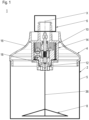
- FIG 1 a schematic view of a preferred embodiment of an electric household appliance 1 according to the invention appliance is shown.
- the electric household appliance 1 is a hand blender, for instance, and has a food container 2, a container cover 4, an electric motor 6 or a drive unit (not shown) comprising an electric motor 6 and a tool 8, for instance a knife.
- the food container 2 is releasably closed by the cover 4 that rests on a wall 5 of the container 2 and supports the motor 6.
- the cover 4 is positioned between the container 2 and the motor 6.
- the tool 8 is positioned inside the container 2 and driven by the motor 6.
- the tool 8 is a cutting tool that rotates around a vertical orientated rotation axis X of the household appliance 1.
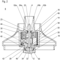
- a gear unit 10 and clutch unit 12 are provided in an area of the cover 4.
- the area of the cover 4 is a gear box 14 which is formed by a middle section of an upper part 16 of the cover 4 and by a lower part 18 of the cover 4.
- the gear unit 10 for instance a planetary gear, has a gear shaft 20 that has an upper coupling section 22.
- the upper coupling section 22 is guided out of the gear box 14 through an upper opening 23 and is adapted to be connected to a not shown motor shaft of the motor 6 via releasable form-fit.
- the upper coupling section 22 has two plate-like coupling elements 24a, 24b.
- the coupling elements 24a, 24b are integrally formed with the gear shaft 20 and extend radially opposed to each other from the gear shaft 20. They are positioned in one single plane, which is according to the shown orientation of the container cover 4 in the figures a vertical plane.
- the gear shaft 20 has a lower coupling section 26 which is in torque proof engagement with an upper counter section 28 of the clutch unit 12.
- the gear shaft 20 is supported by a bearing 30 inside the gear box 14 between its upper coupling section 22 and its lower coupling section 26.
- the clutch unit 12 Beside the upper counter section 28 for the lower coupling section 26 of the gear shaft 20, the clutch unit 12 also has a lower coupling section 32.
- the lower coupling section 32 of the clutch unit 12 extends through a lower opening 34 out of the gear box 14 and is provided to be in releasable form-fit engagement with a tool shaft 36, exemplary shown in figure 1 .
- the clutch unit 12 supports the gear unit 10 in the gear box 14, such that the clutch unit 12 acts as a gear holder.
- the gear unit 10 is guided inside the gear box 14 at two positions; the bearing 30 guides the gear shaft 20 at its upper end close to the upper opening 23, and the clutch unit 12 guides the gear shaft 20 at its lower end close to the lower opening.
- the gear shaft 20 provides a pinion 37 in order to act together with gear wheels of the gear unit 10.
- the gear box 14 is provided by a middle area of the upper part 16 of the cover 4 by the lower part 18 of the cover 4.
- the upper part 16 has a cylindrical protrusion 38 extending downwards from the upper part 16 along the rotation axis Z.
- the protrusion 38 forms a room which is opened at its lower end and acts as a wall of the gear box 14.
- the gear box 14 is closed at its lower end by the lower part 18.
- the lower part 18 acts as a kind of bottom of the gear box 14.
- the lower part 18 is firmly bonded, for instance via ultrasonic welding, to the protrusion 38 of the upper part 38.
- the lower part 18 has a circular outer bonding surface 40 and the protrusion 38 has a corresponding circular inner bonding surface 42.
- the upper part 16 provides the upper opening 23 and the lower part 18 provides the lower opening 34.
- an upper seal 44 and a lower seal 46 are provided.
- the upper seal 44 has an annular shape and is in water resistant contact with an inner circumferential surface 48 inside the gear box 14 directly beyond the upper opening 23 and with an outer circumferential surface of the gear shaft 20.
- the upper seal 44 has a V-like shape.
- the lower seal 46 has also an annular shape and is in water resistant contact with an inner circumferential surface 50 inside the gear box 14 directly above the lower opening 34 and with an outer circumferential surface of the clutch unit 12.
- the lower seal 46 has a V-like shape or a U-like shape, for instance.
- the lower seal 46 is supported by the clutch unit 12, thus facilitating an assembly of the cover 4.
- the upper seal 44 an the lower seal 46 are fixed axially inside the gear box 14 between counterfaces of the upper part 16 and of the lower part 18, which form the upper opening 23 and the lower opening 34. Thereby, they are in direct contact with the bearing 30 and with the clutch unit 12.
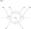
- the upper opening 23 has two radial recesses 52a, 52b ( Figure 4 ).
- the recesses 52a, 52b are opposed to each other and have a shape that correspondents to the plate-like shape of the coupling elements 24a, 24b.
- the upper seal 44 extends radially over these recesses 52a, 52b as well.
- the gear unit 10, the bearing 30, the clutch unit 12, the upper seal 44 and the lower seal 46 are positioned in the opened gear box 14, provided by the protrusion 38 of the upper part 16 of the cover 4. Afterwards, the gear box 14 is closed by material joining the lower part 18 of the cover 4 to the opened lower end of the protrusion 38 of the upper part 18 of the cover 4.
- a container cover of a motor driven electric household appliance such as a hand blender, hand mixer or chopper, wherein the cover provides a gear box which is protected against water penetration, an assembly method and an electric household appliance.
Landscapes
- Engineering & Computer Science (AREA)
- Mechanical Engineering (AREA)
- Food Science & Technology (AREA)
- Food-Manufacturing Devices (AREA)
Abstract
Description
- The invention refers to a container cover of a motor driven electric household appliance, to an assembly method and to a motor driven electric household appliance.
- In general, a container cover of a motor driven electric household appliance such as a hand blender, hand mixer or chopper, provides a gear box in which a gear unit is positioned in order to transfer the rotating speed of a drive shaft of the motor to a tool shaft of a respective tool inside the container. In use, a tool is connected to a clutch which acts together with the gear unit and the cover is put on the cup-shaped container such that the container is closed during food processing. In order to drive the tool, the motor is connected to a gear shaft opposite to the container. After use the cover is cleaned up in order to remove impurities caused by the processing of the food. It has been shown that during cleaning, water can enter into the gear box, thus reducing the lifespan of the gear unit.
- It is an object of the invention to provide a container cover of a motor driven electric household appliance having a gear box which is dishwasher safe, a technical easy assembly method in order to assembly such container cover and a motor driven electric household appliance which container cover having a gear box inside is dishwasher safe.
- This object is solved by a container cover with the features of
claim 1, by an assembly method according toclaim 6, and by a motor driven electric household appliance with the features of claim 7. Advantageous embodiments are disclosed in the dependent claims, the description and the figures. - According to the invention, a container cover of a motor driven electric household appliance such as a hand blender, hand mixer or chopper, is adapted to be put on a food container and to receive the motor opposite to the food container. The cover comprises an upper part and a lower part which can be joined together and form a gear box for receiving a gear unit, a bearing and a clutch unit in order to transfer the rotating speed and the torque of a motor shaft of the motor to a tool shaft of a respective tool inside the container. The upper part has an upper opening in order to guide an upper coupling section of a gear shaft out of the gear box which is adapted to be coupled with the motor shaft directly or indirectly. The lower part has a lower opening in order to guide a lower coupling section of the clutch out of the gear box which is adapted to be coupled with the tool shaft directly or indirectly. An upper seal is directed to the upper opening and a lower seal is directed to the lower opening such that a penetration of water into the gear box is prevented. Exemplary seal are annular rings, consisting of an adequate seal material and having an L-shaped or U-shaped cross-section, whereas a V-shaped seal is preferred.
- Due to the seals, the gear box is protected against water penetration such that the cover can be put into a dishwasher for cleaning or can be cleaned manually via water. As a bearing for the gear shaft is positioned inside the gear box, a precise rotation of the gear shaft is realised.
- In a preferred embodiment, the upper coupling section of the gear shaft is formed integrally with the gear shaft. In order to put the upper section through the upper opening, the upper opening has radial recess(s) adapted to put a respective coupling element of the upper coupling section through. In order to avoid a water penetration through the recess(es), the upper seal extends over the recess(es) radial inwards until it is in seal contact with the gear shaft extending through the upper opening.
- The size of the gear box can be reduced if the clutch unit acts as gear unit holder. Thus, a separate gear unit holder can be omitted.
- Preferably, the upper part and the lower part of the cover are adapted to be joined together by material closure, for instance via ultrasonic welding or bonding. Such joints are easy to install and reliable, in particular water resistant.
- Alternatively, in order to have access to the gear unit or the bearing inside the gear box after the assembly without destroying the joint, the upper part and the lower part of the cover are adapted to be joined together by releasable form fit. One example is a bayonet system, wherein then a further seal is preferred in order to avoid any leakage due the form fit.
- According to an inventive assembly method for such a container cover, a gear unit, a bearing, a clutch unit, an upper seal and a lower seal is positioned in an opened gear box of the cover. Then, the gear box is closed by joining an upper part of the cover and a lower part of the cover together.
- The assembly is easy to execute, characterised by a reduced number of parts, and is applicable for automation.
- An inventive motor driven electric household appliance comprising an inventive container, such enabling a quick and easy cleaning of the household appliance.
- In the following, preferred embodiments of the present invention are explained with respect to the accompanying drawings. As is to be understood, the various elements and components are depicted as examples only, may be facultative and/or combined in a manner different than that depicted. Reference signs for related elements are used comprehensively and not defined again for each figure. Shown is schematically in
- Fig. 1
- a sectional view of a preferred motor driven electric household appliance according to the invention,
- Fig. 2
- an enlarged view of an inventive container cover shown in
figure 1 , - Fig. 3
- an exploded view of the container cover, and
- Fig. 4
- a top view of an upper opening of an upper part of the container cover.
- In
figure 1 , a schematic view of a preferred embodiment of anelectric household appliance 1 according to the invention appliance is shown. Theelectric household appliance 1 is a hand blender, for instance, and has afood container 2, acontainer cover 4, anelectric motor 6 or a drive unit (not shown) comprising anelectric motor 6 and atool 8, for instance a knife. - The
food container 2 is releasably closed by thecover 4 that rests on awall 5 of thecontainer 2 and supports themotor 6. Thus, thecover 4 is positioned between thecontainer 2 and themotor 6. Thetool 8 is positioned inside thecontainer 2 and driven by themotor 6. In the shown embodiment, thetool 8 is a cutting tool that rotates around a vertical orientated rotation axis X of thehousehold appliance 1. - In order to drive the
tool 8 by themotor 6, agear unit 10 andclutch unit 12 are provided in an area of thecover 4. The area of thecover 4 is agear box 14 which is formed by a middle section of anupper part 16 of thecover 4 and by alower part 18 of thecover 4. - As shown in
figures 2 and3 , thegear unit 10, for instance a planetary gear, has agear shaft 20 that has anupper coupling section 22. Theupper coupling section 22 is guided out of thegear box 14 through anupper opening 23 and is adapted to be connected to a not shown motor shaft of themotor 6 via releasable form-fit. In the shown embodiment, theupper coupling section 22 has two plate-like coupling elements coupling elements gear shaft 20 and extend radially opposed to each other from thegear shaft 20. They are positioned in one single plane, which is according to the shown orientation of thecontainer cover 4 in the figures a vertical plane. In addition, thegear shaft 20 has alower coupling section 26 which is in torque proof engagement with anupper counter section 28 of theclutch unit 12. Thegear shaft 20 is supported by a bearing 30 inside thegear box 14 between itsupper coupling section 22 and itslower coupling section 26. - Beside the
upper counter section 28 for thelower coupling section 26 of thegear shaft 20, theclutch unit 12 also has alower coupling section 32. Thelower coupling section 32 of theclutch unit 12 extends through alower opening 34 out of thegear box 14 and is provided to be in releasable form-fit engagement with atool shaft 36, exemplary shown infigure 1 . Further on, theclutch unit 12 supports thegear unit 10 in thegear box 14, such that theclutch unit 12 acts as a gear holder. Thus, thegear unit 10 is guided inside thegear box 14 at two positions; the bearing 30 guides thegear shaft 20 at its upper end close to theupper opening 23, and theclutch unit 12 guides thegear shaft 20 at its lower end close to the lower opening. Thegear shaft 20 provides apinion 37 in order to act together with gear wheels of thegear unit 10. - As mentioned before, the
gear box 14 is provided by a middle area of theupper part 16 of thecover 4 by thelower part 18 of thecover 4. In particular, according to the embodiment shown in thefigures 2 and3 , theupper part 16 has acylindrical protrusion 38 extending downwards from theupper part 16 along the rotation axis Z. Theprotrusion 38 forms a room which is opened at its lower end and acts as a wall of thegear box 14. Thegear box 14 is closed at its lower end by thelower part 18. Thelower part 18 acts as a kind of bottom of thegear box 14. Preferably, thelower part 18 is firmly bonded, for instance via ultrasonic welding, to theprotrusion 38 of theupper part 38. Thereby, it is preferred, when thelower part 18 has a circularouter bonding surface 40 and theprotrusion 38 has a corresponding circularinner bonding surface 42. - The
upper part 16 provides theupper opening 23 and thelower part 18 provides thelower opening 34. In order to avoid any penetration of water through at least one of theseopenings upper seal 44 and alower seal 46 are provided. Theupper seal 44 has an annular shape and is in water resistant contact with an innercircumferential surface 48 inside thegear box 14 directly beyond theupper opening 23 and with an outer circumferential surface of thegear shaft 20. In a cross section and in the preferred embodiment shown here, theupper seal 44 has a V-like shape. Thelower seal 46 has also an annular shape and is in water resistant contact with an innercircumferential surface 50 inside thegear box 14 directly above thelower opening 34 and with an outer circumferential surface of theclutch unit 12. In a cross section and in the preferred embodiment shown here, thelower seal 46 has a V-like shape or a U-like shape, for instance. Preferably, thelower seal 46 is supported by theclutch unit 12, thus facilitating an assembly of thecover 4. In other words, theupper seal 44 an thelower seal 46 are fixed axially inside thegear box 14 between counterfaces of theupper part 16 and of thelower part 18, which form theupper opening 23 and thelower opening 34. Thereby, they are in direct contact with thebearing 30 and with theclutch unit 12. - In order to enable the assembly from the inside to the outside of the opened
gear box 14, theupper opening 23 has tworadial recesses Figure 4 ). Therecesses coupling elements recesses upper seal 44 extends radially over theserecesses - According to a preferred assembly method of the
container cover 4, thegear unit 10, thebearing 30, theclutch unit 12, theupper seal 44 and thelower seal 46 are positioned in the openedgear box 14, provided by theprotrusion 38 of theupper part 16 of thecover 4. Afterwards, thegear box 14 is closed by material joining thelower part 18 of thecover 4 to the opened lower end of theprotrusion 38 of theupper part 18 of thecover 4. - Disclosed are a container cover of a motor driven electric household appliance such as a hand blender, hand mixer or chopper, wherein the cover provides a gear box which is protected against water penetration, an assembly method and an electric household appliance.
-
- 1
- household appliance
- 2
- food container
- 4
- container cover
- 5
- wall of the container
- 6
- electric motor
- 8
- tool
- 10
- gear unit
- 12
- clutch unit
- 14
- gearbox
- 16
- upper part of the cover
- 18
- lower part of the cover
- 20
- gear shaft
- 22
- upper coupling section
- 23
- upper opening
- 24a, b
- coupling element
- 26
- lower coupling section
- 28
- upper counter section
- 30
- bearing
- 32
- lower coupling section
- 34
- lower opening
- 36
- tool shaft
- 37
- pinion
- 38
- protrusion
- 40
- circular inner bonding surface
- 42
- circular outer bonding surface
- 44
- upper seal
- 46
- lower seal
- 48
- inner circumferential surface (upper opening)
- 50
- inner circumferential surface (lower opening)
- 52a, b
- recess
- X
- rotation axis
Claims (7)
- A container cover (4) of a motor driven electric household appliance (1) such as a hand blender, hand mixer or chopper,
wherein• the cover (4) is adapted to be put on a food container and to receive the motor opposite to the food container (2), and• the cover (4) comprises an upper part (16) and a lower part (18) which can be joined together and form a gear box (14) for receiving a gear unit (10), a bearing (30) and a clutch unit (12) in order to transfer the rotating speed and torque of a motor shaft of the motor (6) to a tool shaft (36) of a respective tool (8) inside the container (4),wherein• the upper part (16) has an upper opening (23) in order to guide an upper coupling section (22) of a gear shaft (20) out of the gear box (14) which is adapted to be coupled with the motor shaft directly or indirectly, and• the lower part (18) has a lower opening (34) in order to guide a lower coupling section (32) of the clutch unit (12) out of the gear box (14) which is adapted to be coupled with the tool shaft (36) directly or indirectly, andwherein• an upper seal (44) is directed to the upper opening (23) and a lower seal (46) is directed to the lower opening (34) such that a penetration of water into the gear box (14) is prevented. - The cover according to claim 1, wherein the upper opening (23) has at least one radial recess (52a, 52b) adapted to put a coupling element (24a, 24b) of the upper coupling section (22) through, wherein the upper seal (44) extends over the at least one recess (52a, 52b) radially.
- The cover according to claim 1, wherein the clutch unit (12) acts as gear unit holder.
- The cover according to claim 1, 2 or 3, wherein the upper part (16) and the lower part (18) are adapted to be joined together by material closure.
- The cover according to claim 1, 2 or 3, wherein the upper part (16) and the lower part (18) are adapted to be joined together by form fit.
- An assembly method for a container cover (4) according to any of the preceding claims, comprising the steps:• positioning a gear unit (10), a bearing (30), a clutch unit (12) and an upper seal (44) and a lower seal (46) in opened gear box (14) of the cover (4), and• Closing the gear box (14) by joining an upper part (16) of the cover (4) and a lower part (18) of the cover (4) together.
- A motor driven electric household appliance (1) comprising a container cover (4) according to one of the preceding claims 1 to 5.
Priority Applications (1)
| Application Number | Priority Date | Filing Date | Title |
|---|---|---|---|
| EP22175976.4A EP4285796B1 (en) | 2022-05-30 | 2022-05-30 | Container cover of an electric household appliance, assembling method, and household appliance |
Applications Claiming Priority (1)
| Application Number | Priority Date | Filing Date | Title |
|---|---|---|---|
| EP22175976.4A EP4285796B1 (en) | 2022-05-30 | 2022-05-30 | Container cover of an electric household appliance, assembling method, and household appliance |
Publications (3)
| Publication Number | Publication Date |
|---|---|
| EP4285796A1 true EP4285796A1 (en) | 2023-12-06 |
| EP4285796B1 EP4285796B1 (en) | 2026-01-28 |
| EP4285796C0 EP4285796C0 (en) | 2026-01-28 |
Family
ID=82446686
Family Applications (1)
| Application Number | Title | Priority Date | Filing Date |
|---|---|---|---|
| EP22175976.4A Active EP4285796B1 (en) | 2022-05-30 | 2022-05-30 | Container cover of an electric household appliance, assembling method, and household appliance |
Country Status (1)
| Country | Link |
|---|---|
| EP (1) | EP4285796B1 (en) |
Citations (4)
| Publication number | Priority date | Publication date | Assignee | Title |
|---|---|---|---|---|
| US3302894A (en) * | 1964-04-17 | 1967-02-07 | Gen Electric | Pivoted power unit for portable waste disposer |
| WO2013170459A1 (en) * | 2012-05-16 | 2013-11-21 | 深圳市联创三金电器有限公司 | Dual-speed multifunctional household food processor |
| EP2858542A1 (en) * | 2012-06-08 | 2015-04-15 | Breville Pty Limited | Stick mixer driven food processor |
| US20210251429A1 (en) * | 2018-05-15 | 2021-08-19 | De'longhi Braun Household Gmbh | Domestic appliance for processing foods and splash guard therefor |
-
2022
- 2022-05-30 EP EP22175976.4A patent/EP4285796B1/en active Active
Patent Citations (4)
| Publication number | Priority date | Publication date | Assignee | Title |
|---|---|---|---|---|
| US3302894A (en) * | 1964-04-17 | 1967-02-07 | Gen Electric | Pivoted power unit for portable waste disposer |
| WO2013170459A1 (en) * | 2012-05-16 | 2013-11-21 | 深圳市联创三金电器有限公司 | Dual-speed multifunctional household food processor |
| EP2858542A1 (en) * | 2012-06-08 | 2015-04-15 | Breville Pty Limited | Stick mixer driven food processor |
| US20210251429A1 (en) * | 2018-05-15 | 2021-08-19 | De'longhi Braun Household Gmbh | Domestic appliance for processing foods and splash guard therefor |
Also Published As
| Publication number | Publication date |
|---|---|
| EP4285796B1 (en) | 2026-01-28 |
| EP4285796C0 (en) | 2026-01-28 |
Similar Documents
| Publication | Publication Date | Title |
|---|---|---|
| MXPA00000104A (en) | Device for stirring or grinding foodstuffs. | |
| US4462694A (en) | Agitator assembly for use in blender appliance | |
| RU2719252C2 (en) | Spiral cutting device | |
| JP6967616B2 (en) | Centrifuge rotor with seal | |
| US12137840B2 (en) | Food preparation appliance with a detachable tool | |
| EP4285796B1 (en) | Container cover of an electric household appliance, assembling method, and household appliance | |
| WO2018016097A1 (en) | Variable-speed speed increaser, variable-speed speed-increaser control device, and variable-speed speed-increaser control method | |
| CN110169724A (en) | Food arrangement device with locking device | |
| US4534658A (en) | Mixing apparatus, having seals which may be satisfactorily cleaned, particularly for the pharmaceutical industry | |
| HK92696A (en) | Multi-purpose kitchen appliance | |
| US20070140048A1 (en) | Seal and drain for blenders | |
| CN115697151A (en) | Food processing tools and manufacturing methods | |
| JP2825175B2 (en) | Composite screen | |
| CN107242812B (en) | Mixing foot comprising a drive shaft for rotation by an electric housing | |
| CN108606622A (en) | Cooking apparatus | |
| US20030201110A1 (en) | Grease slinger | |
| KR200476258Y1 (en) | Blade assembly for food processor | |
| CN106190782A (en) | For fermentation tank can the stirring system of on-line cleaning | |
| CN208925794U (en) | Food cooking machine | |
| RU2532147C2 (en) | Kitchen device with treatment bowl | |
| CN211609447U (en) | Convenient clear broken wall machine | |
| CN218338230U (en) | Stirring assembly and cooking utensil with same | |
| CN213216625U (en) | Staving rotating-structure and vegetable washing machine | |
| KR20250167418A (en) | Portable cooking appliance | |
| CN224050723U (en) | Condensation water preventing structure of ice maker |
Legal Events
| Date | Code | Title | Description |
|---|---|---|---|
| PUAI | Public reference made under article 153(3) epc to a published international application that has entered the european phase |
Free format text: ORIGINAL CODE: 0009012 |
|
| STAA | Information on the status of an ep patent application or granted ep patent |
Free format text: STATUS: THE APPLICATION HAS BEEN PUBLISHED |
|
| AK | Designated contracting states |
Kind code of ref document: A1 Designated state(s): AL AT BE BG CH CY CZ DE DK EE ES FI FR GB GR HR HU IE IS IT LI LT LU LV MC MK MT NL NO PL PT RO RS SE SI SK SM TR |
|
| STAA | Information on the status of an ep patent application or granted ep patent |
Free format text: STATUS: REQUEST FOR EXAMINATION WAS MADE |
|
| 17P | Request for examination filed |
Effective date: 20240606 |
|
| RBV | Designated contracting states (corrected) |
Designated state(s): AL AT BE BG CH CY CZ DE DK EE ES FI FR GB GR HR HU IE IS IT LI LT LU LV MC MK MT NL NO PL PT RO RS SE SI SK SM TR |
|
| GRAP | Despatch of communication of intention to grant a patent |
Free format text: ORIGINAL CODE: EPIDOSNIGR1 |
|
| STAA | Information on the status of an ep patent application or granted ep patent |
Free format text: STATUS: GRANT OF PATENT IS INTENDED |
|
| INTG | Intention to grant announced |
Effective date: 20250923 |
|
| GRAS | Grant fee paid |
Free format text: ORIGINAL CODE: EPIDOSNIGR3 |
|
| GRAA | (expected) grant |
Free format text: ORIGINAL CODE: 0009210 |
|
| STAA | Information on the status of an ep patent application or granted ep patent |
Free format text: STATUS: THE PATENT HAS BEEN GRANTED |
|
| AK | Designated contracting states |
Kind code of ref document: B1 Designated state(s): AL AT BE BG CH CY CZ DE DK EE ES FI FR GB GR HR HU IE IS IT LI LT LU LV MC MK MT NL NO PL PT RO RS SE SI SK SM TR |
|
| REG | Reference to a national code |
Ref country code: CH Ref legal event code: F10 Free format text: ST27 STATUS EVENT CODE: U-0-0-F10-F00 (AS PROVIDED BY THE NATIONAL OFFICE) Effective date: 20260128 Ref country code: GB Ref legal event code: FG4D |
|
| REG | Reference to a national code |
Ref country code: DE Ref legal event code: R096 Ref document number: 602022029091 Country of ref document: DE |
|
| REG | Reference to a national code |
Ref country code: IE Ref legal event code: FG4D |
|
| U01 | Request for unitary effect filed |
Effective date: 20260227 |
|
| U07 | Unitary effect registered |
Designated state(s): AT BE BG DE DK EE FI FR IT LT LU LV MT NL PT RO SE SI Effective date: 20260306 |
|
| PG25 | Lapsed in a contracting state [announced via postgrant information from national office to epo] |
Ref country code: RS Free format text: LAPSE BECAUSE OF FAILURE TO SUBMIT A TRANSLATION OF THE DESCRIPTION OR TO PAY THE FEE WITHIN THE PRESCRIBED TIME-LIMIT Effective date: 20260428 |
|
| PG25 | Lapsed in a contracting state [announced via postgrant information from national office to epo] |
Ref country code: ES Free format text: LAPSE BECAUSE OF FAILURE TO SUBMIT A TRANSLATION OF THE DESCRIPTION OR TO PAY THE FEE WITHIN THE PRESCRIBED TIME-LIMIT Effective date: 20260128 |
|
| PG25 | Lapsed in a contracting state [announced via postgrant information from national office to epo] |
Ref country code: PL Free format text: LAPSE BECAUSE OF FAILURE TO SUBMIT A TRANSLATION OF THE DESCRIPTION OR TO PAY THE FEE WITHIN THE PRESCRIBED TIME-LIMIT Effective date: 20260128 |
|
| PG25 | Lapsed in a contracting state [announced via postgrant information from national office to epo] |
Ref country code: GR Free format text: LAPSE BECAUSE OF FAILURE TO SUBMIT A TRANSLATION OF THE DESCRIPTION OR TO PAY THE FEE WITHIN THE PRESCRIBED TIME-LIMIT Effective date: 20260429 |
|
| PG25 | Lapsed in a contracting state [announced via postgrant information from national office to epo] |
Ref country code: NO Free format text: LAPSE BECAUSE OF FAILURE TO SUBMIT A TRANSLATION OF THE DESCRIPTION OR TO PAY THE FEE WITHIN THE PRESCRIBED TIME-LIMIT Effective date: 20260428 |
|
| U20 | Renewal fee for the european patent with unitary effect paid |
Year of fee payment: 5 Effective date: 20260608 |
|
| PG25 | Lapsed in a contracting state [announced via postgrant information from national office to epo] |
Ref country code: HR Free format text: LAPSE BECAUSE OF FAILURE TO SUBMIT A TRANSLATION OF THE DESCRIPTION OR TO PAY THE FEE WITHIN THE PRESCRIBED TIME-LIMIT Effective date: 20260128 |
|
| PG25 | Lapsed in a contracting state [announced via postgrant information from national office to epo] |
Ref country code: IS Free format text: LAPSE BECAUSE OF FAILURE TO SUBMIT A TRANSLATION OF THE DESCRIPTION OR TO PAY THE FEE WITHIN THE PRESCRIBED TIME-LIMIT Effective date: 20260528 |