EP4285013B1 - An assembly for direct injection of gaseous fuel in a cylinder of a two-stroke internal combustion piston engine and a two-stroke internal com-bustion piston engine - Google Patents
An assembly for direct injection of gaseous fuel in a cylinder of a two-stroke internal combustion piston engine and a two-stroke internal com-bustion piston engine Download PDFInfo
- Publication number
- EP4285013B1 EP4285013B1 EP21702258.1A EP21702258A EP4285013B1 EP 4285013 B1 EP4285013 B1 EP 4285013B1 EP 21702258 A EP21702258 A EP 21702258A EP 4285013 B1 EP4285013 B1 EP 4285013B1
- Authority
- EP
- European Patent Office
- Prior art keywords
- liquefied gas
- enclosure
- cylinder
- engine
- fuel
- Prior art date
- Legal status (The legal status is an assumption and is not a legal conclusion. Google has not performed a legal analysis and makes no representation as to the accuracy of the status listed.)
- Active
Links
Images
Classifications
-
- F—MECHANICAL ENGINEERING; LIGHTING; HEATING; WEAPONS; BLASTING
- F02—COMBUSTION ENGINES; HOT-GAS OR COMBUSTION-PRODUCT ENGINE PLANTS
- F02M—SUPPLYING COMBUSTION ENGINES IN GENERAL WITH COMBUSTIBLE MIXTURES OR CONSTITUENTS THEREOF
- F02M21/00—Apparatus for supplying engines with non-liquid fuels, e.g. gaseous fuels stored in liquid form
- F02M21/02—Apparatus for supplying engines with non-liquid fuels, e.g. gaseous fuels stored in liquid form for gaseous fuels
- F02M21/0203—Apparatus for supplying engines with non-liquid fuels, e.g. gaseous fuels stored in liquid form for gaseous fuels characterised by the type of gaseous fuel
- F02M21/0209—Hydrocarbon fuels, e.g. methane or acetylene
- F02M21/0212—Hydrocarbon fuels, e.g. methane or acetylene comprising at least 3 C-Atoms, e.g. liquefied petroleum gas [LPG], propane or butane
-
- F—MECHANICAL ENGINEERING; LIGHTING; HEATING; WEAPONS; BLASTING
- F02—COMBUSTION ENGINES; HOT-GAS OR COMBUSTION-PRODUCT ENGINE PLANTS
- F02D—CONTROLLING COMBUSTION ENGINES
- F02D19/00—Controlling engines characterised by their use of non-liquid fuels, pluralities of fuels, or non-fuel substances added to the combustible mixtures
- F02D19/02—Controlling engines characterised by their use of non-liquid fuels, pluralities of fuels, or non-fuel substances added to the combustible mixtures peculiar to engines working with gaseous fuels
- F02D19/025—Failure diagnosis or prevention; Safety measures; Testing
-
- F—MECHANICAL ENGINEERING; LIGHTING; HEATING; WEAPONS; BLASTING
- F02—COMBUSTION ENGINES; HOT-GAS OR COMBUSTION-PRODUCT ENGINE PLANTS
- F02D—CONTROLLING COMBUSTION ENGINES
- F02D19/00—Controlling engines characterised by their use of non-liquid fuels, pluralities of fuels, or non-fuel substances added to the combustible mixtures
- F02D19/06—Controlling engines characterised by their use of non-liquid fuels, pluralities of fuels, or non-fuel substances added to the combustible mixtures peculiar to engines working with pluralities of fuels, e.g. alternatively with light and heavy fuel oil, other than engines indifferent to the fuel consumed
- F02D19/0639—Controlling engines characterised by their use of non-liquid fuels, pluralities of fuels, or non-fuel substances added to the combustible mixtures peculiar to engines working with pluralities of fuels, e.g. alternatively with light and heavy fuel oil, other than engines indifferent to the fuel consumed characterised by the type of fuels
- F02D19/0642—Controlling engines characterised by their use of non-liquid fuels, pluralities of fuels, or non-fuel substances added to the combustible mixtures peculiar to engines working with pluralities of fuels, e.g. alternatively with light and heavy fuel oil, other than engines indifferent to the fuel consumed characterised by the type of fuels at least one fuel being gaseous, the other fuels being gaseous or liquid at standard conditions
- F02D19/0647—Controlling engines characterised by their use of non-liquid fuels, pluralities of fuels, or non-fuel substances added to the combustible mixtures peculiar to engines working with pluralities of fuels, e.g. alternatively with light and heavy fuel oil, other than engines indifferent to the fuel consumed characterised by the type of fuels at least one fuel being gaseous, the other fuels being gaseous or liquid at standard conditions the gaseous fuel being liquefied petroleum gas [LPG], liquefied natural gas [LNG], compressed natural gas [CNG] or dimethyl ether [DME]
-
- F—MECHANICAL ENGINEERING; LIGHTING; HEATING; WEAPONS; BLASTING
- F02—COMBUSTION ENGINES; HOT-GAS OR COMBUSTION-PRODUCT ENGINE PLANTS
- F02D—CONTROLLING COMBUSTION ENGINES
- F02D19/00—Controlling engines characterised by their use of non-liquid fuels, pluralities of fuels, or non-fuel substances added to the combustible mixtures
- F02D19/06—Controlling engines characterised by their use of non-liquid fuels, pluralities of fuels, or non-fuel substances added to the combustible mixtures peculiar to engines working with pluralities of fuels, e.g. alternatively with light and heavy fuel oil, other than engines indifferent to the fuel consumed
- F02D19/0663—Details on the fuel supply system, e.g. tanks, valves, pipes, pumps, rails, injectors or mixers
- F02D19/0684—High pressure fuel injection systems; Details on pumps, rails or the arrangement of valves in the fuel supply and return systems
-
- F—MECHANICAL ENGINEERING; LIGHTING; HEATING; WEAPONS; BLASTING
- F02—COMBUSTION ENGINES; HOT-GAS OR COMBUSTION-PRODUCT ENGINE PLANTS
- F02M—SUPPLYING COMBUSTION ENGINES IN GENERAL WITH COMBUSTIBLE MIXTURES OR CONSTITUENTS THEREOF
- F02M21/00—Apparatus for supplying engines with non-liquid fuels, e.g. gaseous fuels stored in liquid form
- F02M21/02—Apparatus for supplying engines with non-liquid fuels, e.g. gaseous fuels stored in liquid form for gaseous fuels
- F02M21/0218—Details on the gaseous fuel supply system, e.g. tanks, valves, pipes, pumps, rails, injectors or mixers
-
- F—MECHANICAL ENGINEERING; LIGHTING; HEATING; WEAPONS; BLASTING
- F02—COMBUSTION ENGINES; HOT-GAS OR COMBUSTION-PRODUCT ENGINE PLANTS
- F02M—SUPPLYING COMBUSTION ENGINES IN GENERAL WITH COMBUSTIBLE MIXTURES OR CONSTITUENTS THEREOF
- F02M21/00—Apparatus for supplying engines with non-liquid fuels, e.g. gaseous fuels stored in liquid form
- F02M21/02—Apparatus for supplying engines with non-liquid fuels, e.g. gaseous fuels stored in liquid form for gaseous fuels
- F02M21/0218—Details on the gaseous fuel supply system, e.g. tanks, valves, pipes, pumps, rails, injectors or mixers
- F02M21/0245—High pressure fuel supply systems; Rails; Pumps; Arrangement of valves
-
- F—MECHANICAL ENGINEERING; LIGHTING; HEATING; WEAPONS; BLASTING
- F02—COMBUSTION ENGINES; HOT-GAS OR COMBUSTION-PRODUCT ENGINE PLANTS
- F02M—SUPPLYING COMBUSTION ENGINES IN GENERAL WITH COMBUSTIBLE MIXTURES OR CONSTITUENTS THEREOF
- F02M21/00—Apparatus for supplying engines with non-liquid fuels, e.g. gaseous fuels stored in liquid form
- F02M21/02—Apparatus for supplying engines with non-liquid fuels, e.g. gaseous fuels stored in liquid form for gaseous fuels
- F02M21/0218—Details on the gaseous fuel supply system, e.g. tanks, valves, pipes, pumps, rails, injectors or mixers
- F02M21/0293—Safety devices; Fail-safe measures
-
- F—MECHANICAL ENGINEERING; LIGHTING; HEATING; WEAPONS; BLASTING
- F02—COMBUSTION ENGINES; HOT-GAS OR COMBUSTION-PRODUCT ENGINE PLANTS
- F02M—SUPPLYING COMBUSTION ENGINES IN GENERAL WITH COMBUSTIBLE MIXTURES OR CONSTITUENTS THEREOF
- F02M21/00—Apparatus for supplying engines with non-liquid fuels, e.g. gaseous fuels stored in liquid form
- F02M21/02—Apparatus for supplying engines with non-liquid fuels, e.g. gaseous fuels stored in liquid form for gaseous fuels
- F02M21/06—Apparatus for de-liquefying, e.g. by heating
-
- Y—GENERAL TAGGING OF NEW TECHNOLOGICAL DEVELOPMENTS; GENERAL TAGGING OF CROSS-SECTIONAL TECHNOLOGIES SPANNING OVER SEVERAL SECTIONS OF THE IPC; TECHNICAL SUBJECTS COVERED BY FORMER USPC CROSS-REFERENCE ART COLLECTIONS [XRACs] AND DIGESTS
- Y02—TECHNOLOGIES OR APPLICATIONS FOR MITIGATION OR ADAPTATION AGAINST CLIMATE CHANGE
- Y02T—CLIMATE CHANGE MITIGATION TECHNOLOGIES RELATED TO TRANSPORTATION
- Y02T10/00—Road transport of goods or passengers
- Y02T10/10—Internal combustion engine [ICE] based vehicles
- Y02T10/30—Use of alternative fuels, e.g. biofuels
Definitions
- the present invention relates to an assembly for direct injection of gaseous fuel in a cylinder of a two-stroke internal combustion piston engine according to the preamble of claim 1.
- Invention relates also to a two-stroke internal combustion piston engine provided with a direct injection gaseous fuel feeding system.
- Internal combustion piston engine is widely utilized in providing mechanical power in land-based power plant and in marine vessel for producing electric power and/or propulsion power.
- a dual-fuel engine uses a low-pressure gaseous fuel such as natural gas that is mixed at relatively low pressure with intake air admitted into the engine cylinders.
- the air/gaseous fuel mixture that is provided to the cylinder under certain operating conditions is compressed and then ignited using a spark ignition or using a compression ignition pilot fuel, such as light fuel oil, which is injected into the air/gaseous fuel mixture present in the cylinder.
- a direct injection gas engine is also known as such, in which a gaseous fuel, such as liquefied natural gas (LNG), is injected into the cylinder at high-pressure while combustion in the cylinder from a diesel pilot is already underway.
- LNG liquefied natural gas
- the direct injection gas engines operate on the gaseous fuel, and the diesel pilot provides ignition of the gaseous fuel.
- DK179056B1 discloses a fuel supply system for supplying high-pressure gas to a large two-stroke compression-ignited internal combustion engine.
- the engine is provided with a fuel injection system for injecting the supplied high-pressure gas into the combustion chambers of the engine.
- the fuel supply system comprises a feed conduit connecting an outlet of a liquefied gas storage tank to the inlet of a high-pressure pump for transporting liquefied gas from the liquefied gas storage tank to the high-pressure pump, a transfer conduit connecting the outlet of the high-pressure pump to the inlet of a high-pressure vaporizer for transporting high-pressure liquefied gas from the high-pressure pump to the high-pressure vaporizer, a supply conduit connecting the outlet of the high-pressure vaporizer to an inlet of the fuel injection system of the engine for transporting high-pressure vaporized gas to the fuel injection system of the engine.
- the high-pressure pump comprises two or more pump units. Each pump unit comprises a pump piston slidably disposed in a pump cylinder and a hydraulically powered drive piston slidably disposed in a drive cylinder with the drive piston coupled to the pump piston for driving the pump piston.
- US918808069 B2 discloses an engine fuel system having liquid and gaseous fuel systems, each of which injects fuel directly into an engine cylinder.
- the gaseous fuel system is a direct injection gas system which comprises a liquefied gas storage, liquefied gas pump, liquefied gas evaporator and gaseous gas fuel rail connected to a fuel injector.
- a gaseous fuel direct injection fuel supply system needs to be configured such that gas at substantially high-pressure is delivered to the gas injectors arranged to the cylinders of the engine.
- An object of the invention is to provide an assembly for direct injection of gaseous fuel in a cylinder of a two-stroke internal combustion piston engine which is considerably improved compared to the prior art solutions.
- An object of the invention is to provide two-stoke internal combustion piston engine having a direct injection gaseous fuel feeding system which is considerably improved compared to the prior art solutions for gas operated large two-stroke internal combustion piston engines.
- the assembly is therefore configured to pump the liquefied gas in liquid phase, cryogenic conditions, and evaporate the pumped gas into gaseous form, which may be administered to the cylinder by the gaseous gas fuel injector.
- the fuel injection system utilizing liquefied gas is provided for a large two-stroke engine which can be easily modularized. Safety issues relating to gaseous fuel are taken care of by the enclosure which is common for the liquefied gas supply manifold and the liquefied gas return manifold, a liquefied gas high-pressure pump unit.
- the assembly can be readily installed to an existing large two-stroke engine, because it is configured to be assembled on top of the engine.
- the enclosure is provided with an air inlet and an outlet connectable to a blower arranged to the assembly. This makes it possible to connect the outlet to a blower for conveying possibly leaked fuel safely away from the engine.
- the liquefied gas supply manifold in the enclosure is a single wall manifold and the liquefied gas return manifold in the enclosure is a single wall manifold.
- the fuel feed line outside the enclosure is provided with a separate double wall which forms an intermediate space inside the double wall and that the enclosure is provided with a lead-through block via which the fuel feed line is led from the enclosure to the heat exchanger unit, which lead-through block separates the intermediate space of the fuel feed line from the space of the enclosure.
- the assembly comprises a gaseous gas accumulator connected to the gaseous gas outlet of the heat exchanger unit by means of the fuel feed line.
- the assembly comprises an enclosure and the assembly is configured for a multi-cylinder two-stroke internal combustion piston engine comprising a several cylinders arranged in a line of cylinders, wherein
- the assembly is configured for a multi-cylinder two-stroke internal combustion piston engine comprising a several cylinders arranged in a line of cylinders, and
- the liquefied gas supply manifold is an assembly of multiple gas supply manifold sections, comprising one supply manifold section for each cylinder of the engine.
- the liquefied gas return manifold is an assembly of multiple gas return manifold sections, comprising one return manifold section for each cylinder of the engine.
- the assembly comprises several fuel delivery lines for the cylinders of the engine, each fuel delivery line comprising
- a two-stroke internal combustion piston engine comprises more than one cylinders in which each cylinder is provided with an assembly according to anyone of the claims 6 and 7.
- the enclosure has a length extending from a first cylinder in the line of cylinders to the last cylinder in the line of cylinders of the engine.
- the enclosure, the liquefied gas supply manifold, the liquefied gas return manifold and the liquefied high-pressure pump units are arranged on and attached to the top of engine.
- the engine comprises one fuel delivery line for each cylinders (100) of the engine.
- the assembly according to the invention and its various embodiments are applicable for use liquefied combustible gas for direct injection of gaseous fuel into a cylinder of an internal combustion piston engine, and combustion therein.
- liquefied ammonia, liquefied natural gas or liquefied petroleum gas as suitable fuel materials.
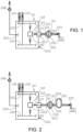
- Figure 1 depicts schematically a simplified assembly 50 for direct injection of gaseous fuel into a cylinder 100 of a two-stroke internal combustion piston engine 1.
- the assembly is configured to attend to injecting gaseous fuel directly to one combustion chamber of the engine, while the fuel is pressurized to injection pressure in liquid phase.
- the assembly 50 comprises a liquefied gas supply manifold section 120 and a liquefied gas return manifold section 140 which are arranged parallel with each other.
- the manifold sections are formed using advantageously pipes and flanges.
- the word section refers to the fact that the assembly in the figure 1 is for one cylinder and usually the engine has more than one cylinders.
- the manifold is formed of respective number of manifold sections coupled with each other by means of the flanges.
- the assembly in the figure 1 depicts the minimum components of a fuel delivery line for one cylinder of the engine.
- the engine comprises several cylinders in a line, arranged one after the other, the engine is provided with corresponding number of assemblies 50, connected to each other such that the liquefied gas supply manifold 120' and a liquefied gas return manifold 140' extend from the first cylinder in the line of cylinders to the last cylinder in the line of cylinders (see the figure 3 ).
- the liquefied gas supply manifold 120' is connected to a liquefied gas supply pipe 130 and the liquefied gas return manifold 140' is connected to a liquefied gas return pipe 150.
- the assembly comprises further a liquefied gas high-pressure pump unit 160, which is connected to the liquefied gas supply manifold section 120 and to the liquefied gas return manifold section 140.
- the liquefied gas tends to heat in the pump due to the pumping and heat transfer from the surroundings.
- the pump is provided with heat insulation to minimize undesired warming of the liquefied gas in the pump at the pumping stage.
- the pump is provided, in addition to the connection to the liquefied gas supply manifold section 120, a connection to the liquefied gas return manifold section 140.
- the liquefied gas at cryogenic conditions is partly circulated through the liquefied gas high-pressure pump unit 160 such that part of the liquefied gas which flows from the liquefied gas supply manifold 120 to the liquefied gas high-pressure pump unit 160 is guided to the liquefied gas return manifold 140 to be returned to a source of liquefied gas.
- the liquefied gas high-pressure pump unit 160 comprises preferably a hydraulically operated piston pump.
- the pump is driven by high pressure hydraulic fluid such that is comprises a drive part to which the hydraulic fluid is guided to reciprocate the drive part and the piston of the pump.
- the liquefied gas at elevated pressure is guided via the high-pressure liquefied gas outlet 180 to a heat exchanger unit 200 which is configured to evaporate the liquefied gas into gaseous form and to heat the gaseous gas to suitable level for injection into the engine.
- the heat exchanger unit 200 is in flow connection with the high-pressure liquefied gas outlet 180 and at least one gaseous gas fuel injector 220.
- the heat exchanger unit 200 is provided with a liquefied gas inlet 201 and a gaseous gas outlet 202, the liquefied gas inlet being connected to the high-pressure outlet of the liquefied gas high-pressure pump unit 160 by means of a fuel feed line 320, more particularly the second fuel feed line 340 outside the enclosure 102.
- the assembly comprises an enclosure 102, which encloses the liquefied gas supply manifold section 120, the liquefied gas return manifold section 140 and the liquefied gas high-pressure pump unit 160.
- the components containing liquefied or gaseous gas outside the enclosure 102 are provided with a separate double wall 110 which forms an intermediate space inside the double wall 110 bordering the inner space containing gas.
- pipes are provided with another pipe outside the inner pipe leaving an intermediate space therebetween.
- a portion of the fuel feed line 320 is inside the enclosure, which may be called as the first fuel feed line 321.
- a portion of the fuel feed line 320 is outside the enclosure 102, which may be called as the second fuel feed line 340.
- the first fuel feed line 321 is made of single wall pipe while the second fuel feed line 340 is made of double wall pipe.
- the assembly comprises a lead-through block 103 in a wall of the enclosure.
- the lead-through block 103 is provided with conduit 320' to which the first fuel feed line 321 inside the enclosure 102, and the second fuel feed line 340 outside the enclosure 102 are connected with each other.
- the lead-through block 103 separates the intermediate space of the fuel feed line 320 from the space of the enclosure 102.
- the lead-through block 103 also seals the connection of the internal space of the enclosure from the surroundings.
- a leak from a high-pressure line 320 between the pump and the injector 220 is the most likely point for the leakage because the pressure is considerably high, for example 15 MPa, at that portion of the fuel feed line.
- the leak flows into the enclosure 102.
- the leak flows into an intermediate space of the line, which is separated by the lead-through block 103 from the inner space of the enclosure 102.
- the volume of the portion of the first fuel feed line 321 inside the enclosure is so small, that the large volume of the enclosure 102, together with the ventilation of it will take care of the leak easily.
- the components containing liquefied gas within the enclosure are provided with a single wall bordering the inner space containing liquefied gas. Possible leak of gas of the components containing liquefied or gaseous gas outside the enclosure 102 is detected and handled suitably. Any gas leaked from the second fuel feed line 340 to the intermediate space between inner and outer pipes maybe led by separate piping (not shown) to further processing.
- the liquefied gas supply manifold section 120 is a single wall manifold and respectively the liquefied gas return manifold section 140 is a single wall manifold. It should be noted that the fuel gas is in liquid phase until it is evaporated in the heat exchanger unit 200.
- the assembly can be utilized as a gaseous fuel injection module for one cylinder of the engine and when applied to a multi-cylinder engine, the engine is provided with the assembly for each one of its cylinder, wherein the liquefied gas supply manifold sections 120 of the assembly are connected with each other and the liquefied gas return manifold sections 140 of the assembly are, respectively, connected with each other to form manifolds extending parallel to each other from a first cylinder to a last cylinder in a line of cylinders in the engine.
- the blower 280 may be comprised of one or several blowers connected suitably to obtained desired flow rate and under-pre sure in the enclosure 102. It should be noted that only one air outlet is needed even if several assemblies are provided for serving fuel injection to several cylinders of an engine.
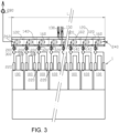
- Figure 2 discloses schematically an assembly 5 for direct injection of gaseous fuel into a cylinder 100 of a two-stroke internal combustion piston engine which has been further developed from the assembly shown in the figure 1 .
- the gas feed line 320 particularly the part of the second feed line 340 containing gaseous fuel, has adequate volume to act as a fuel accumulator.
- the exchanger unit 200 is also in connection with a suitable heat source.
- the assembly is configured to pressurize and evaporate liquefied gas fuel and attend to injecting gaseous fuel directly to one combustion chamber.
- the assembly 50 shown in the figure 2 is otherwise similar to that shown in the figure 1 but here the assembly comprises a separate gaseous gas accumulator 300 connected to the gaseous gas outlet of the heat exchanger unit by means of the fuel feed line 320.
- Figure 3 describes the assembly for direct injection of gaseous fuel in a cylinder of a two-stroke, multi-cylinder internal combustion piston engine 1.
- the large two-stroke crosshead engine which is depicted in the figure 3 , comprises more than one, usually more than six cylinders 100 in a line.
- the large 2-stroke engine to which the gaseous fuel feeding system according to the invention is specifically intended, is a low speed, crosshead engine, having a cylinder bore diameter from about 50 cm up to 1m and stroke length of about 2,5 to 3,0 meters.
- each one of the cylinders 100 is provided with the assembly according to figure 2 .
- the assembly comprises for each cylinder at least two fuel injectors 220, which both are connected to a shared, or a common accumulator 300.
- the enclosure 102 When applied to a multi-cylinder two-stroke engine the enclosure 102 has a length L which substantially corresponds to the length of a line of the cylinders 100 of the engine. In other words, the enclosure extends from a first cylinder in the line of cylinders to the last cylinder in the line of cylinders of the engine 1.
- the enclosure 102 is provided with an air inlet 240 and an outlet 280 at opposite ends of the enclosure 102.
- the enclosure can be formed of several distinct section connected to one another.
- the air outlet 260 is connected to a blower 280. It should be noted that only one air outlet is needed but instead of one air outlet the enclosure may be provided with two, or even more outlets, even if several assemblies according to figure 2 are provided for serving fuel injection to several cylinders of an engine.
- the enclosure 102 encloses the liquefied gas supply manifold 120' and the liquefied gas return manifold 140' totally and the liquefied gas high-pressure pump units 160, as well.
- the components containing liquefied gas within the enclosure are provided with a single wall bordering the inner space containing liquefied gas and the common enclosure.
- the liquefied gas supply manifold 120' and respectively the liquefied gas return manifold 140' can be called as single wall manifolds.
- the components containing liquefied or gaseous gas outside the enclosure 102 in turn, are provided with a double wall bordering the gaseous fuel feed line 320 which contains and delivers gas to the injectors 220.
- the engine comprises one fuel delivery line for each one of the cylinders 100 of the engine.
- the assembly comprises several fuel delivery lines for the cylinders of the engine, each fuel delivery line comprising one liquefied gas high-pressure pump unit 160 connected to the liquefied gas supply manifold 120' and to the liquefied gas return manifold 140', one heat exchanger unit 200 configured to evaporate the liquefied gas and heating the gaseous gas, and one gaseous gas accumulator 240 to which the number of fuel injectors 220 are connected for receiving gaseous fuel.
- the liquefied gas supply manifold 120' is an assembly of multiple gas supply manifold sections 120, comprising one supply manifold section for each cylinder 100 of the engine, as is depicted in the figure 2 .
- the liquefied gas return manifold 140' is an assembly of multiple gas return manifold sections 140, comprising one return manifold section for each cylinder of the engine.
- the liquefied gas supply manifold 120' and the liquefied gas return manifold 140', as well as each one of the liquefied gas high-pressure pumps 160 units are arranged within the common enclosure 102 and the heat exchanger units 200, and the gaseous gas accumulators 240 are arranged outside the enclosure 102.
- the accumulator for each cylinder can be installed near the injectors, on top of the respective cylinder head.
- the enclosure 102 is provided for safety reasons. Should there be a leak in the fuel system within the enclosure, the leaked gas can be led away for further processing by means of the blower 280. A leak from a high-pressure line between the pump and the injector 220 is the most likely point for the leakage.
- the volume in one single-wall high-pressure line is so small, that the large volume of the enclosure 102 and ventilation of it will take care of the leak easily.
- corresponding pump can be immediately shut down quickly, and the leaked amount of gas will remain relatively small compared to the ventilated volume of the enclosure 102.
- the assembly comprising enclosure 102, the liquefied gas supply manifold 120', the liquefied gas return manifold 140' and the liquefied high-pressure pump units 160 are arranged on top of engine.
- the assembly is supported by means of suitable support structure, which is attached to the engine.
- the assembly is arranged above the cylinder heads of the engine.
Landscapes
- Engineering & Computer Science (AREA)
- Chemical & Material Sciences (AREA)
- Combustion & Propulsion (AREA)
- Mechanical Engineering (AREA)
- General Engineering & Computer Science (AREA)
- Oil, Petroleum & Natural Gas (AREA)
- Chemical Kinetics & Catalysis (AREA)
- General Chemical & Material Sciences (AREA)
- Health & Medical Sciences (AREA)
- Biomedical Technology (AREA)
- Fuel-Injection Apparatus (AREA)
Description
- The present invention relates to an assembly for direct injection of gaseous fuel in a cylinder of a two-stroke internal combustion piston engine according to the preamble of
claim 1. Invention relates also to a two-stroke internal combustion piston engine provided with a direct injection gaseous fuel feeding system. - Internal combustion piston engine is widely utilized in providing mechanical power in land-based power plant and in marine vessel for producing electric power and/or propulsion power.
- A dual-fuel engine uses a low-pressure gaseous fuel such as natural gas that is mixed at relatively low pressure with intake air admitted into the engine cylinders. The air/gaseous fuel mixture that is provided to the cylinder under certain operating conditions is compressed and then ignited using a spark ignition or using a compression ignition pilot fuel, such as light fuel oil, which is injected into the air/gaseous fuel mixture present in the cylinder.
- A direct injection gas engine is also known as such, in which a gaseous fuel, such as liquefied natural gas (LNG), is injected into the cylinder at high-pressure while combustion in the cylinder from a diesel pilot is already underway. The direct injection gas engines operate on the gaseous fuel, and the diesel pilot provides ignition of the gaseous fuel.
-
DK179056B1 -
US918808069 B2 discloses an engine fuel system having liquid and gaseous fuel systems, each of which injects fuel directly into an engine cylinder. The gaseous fuel system is a direct injection gas system which comprises a liquefied gas storage, liquefied gas pump, liquefied gas evaporator and gaseous gas fuel rail connected to a fuel injector. - A gaseous fuel direct injection fuel supply system needs to be configured such that gas at substantially high-pressure is delivered to the gas injectors arranged to the cylinders of the engine.
- Both of the above mentioned prior art documents suggest to control the operation of the gaseous fuel pump by control fluid which operates the high-pressure piston pump. Variable control of the high-pressure pump requires a variable high-pressure pump of the control fluid system. The prior art solutions have a general problem of complexity in structure of liquefied gas pump and its controllability.
- Other systems are known for example from
WO 2018/202313 A1 andUS 6 095 101 A . - An object of the invention is to provide an assembly for direct injection of gaseous fuel in a cylinder of a two-stroke internal combustion piston engine which is considerably improved compared to the prior art solutions.
- An object of the invention is to provide two-stoke internal combustion piston engine having a direct injection gaseous fuel feeding system which is considerably improved compared to the prior art solutions for gas operated large two-stroke internal combustion piston engines.
- Objects of the invention can be met substantially as is disclosed in the independent claim and in the other claims describing more details of different embodiments of the invention.
- The assembly is therefore configured to pump the liquefied gas in liquid phase, cryogenic conditions, and evaporate the pumped gas into gaseous form, which may be administered to the cylinder by the gaseous gas fuel injector. The fuel injection system utilizing liquefied gas is provided for a large two-stroke engine which can be easily modularized. Safety issues relating to gaseous fuel are taken care of by the enclosure which is common for the liquefied gas supply manifold and the liquefied gas return manifold, a liquefied gas high-pressure pump unit. The assembly can be readily installed to an existing large two-stroke engine, because it is configured to be assembled on top of the engine.
- According to an embodiment of the invention the enclosure is provided with an air inlet and an outlet connectable to a blower arranged to the assembly. This makes it possible to connect the outlet to a blower for conveying possibly leaked fuel safely away from the engine.
- According to an embodiment of the invention the liquefied gas supply manifold in the enclosure is a single wall manifold and the liquefied gas return manifold in the enclosure is a single wall manifold.
- According to the invention the fuel feed line outside the enclosure is provided with a separate double wall which forms an intermediate space inside the double wall and that the enclosure is provided with a lead-through block via which the fuel feed line is led from the enclosure to the heat exchanger unit, which lead-through block separates the intermediate space of the fuel feed line from the space of the enclosure.
- According to an embodiment of the invention the assembly comprises a gaseous gas accumulator connected to the gaseous gas outlet of the heat exchanger unit by means of the fuel feed line.
- According to the invention the assembly comprises an enclosure and the assembly is configured for a multi-cylinder two-stroke internal combustion piston engine comprising a several cylinders arranged in a line of cylinders, wherein
- the enclosure has a length of the line of cylinders,
- and the enclosure is provided with an air inlet and an outlet at opposite ends of the enclosure.
- According to an embodiment of the invention the assembly is configured for a multi-cylinder two-stroke internal combustion piston engine comprising a several cylinders arranged in a line of cylinders, and
- the liquefied gas supply manifold, the liquefied gas return manifold and the liquefied gas high-pressure pump unit are arranged within the enclosure, and
- the heat exchanger unit, and the gaseous gas accumulator are arranged outside the enclosure.
- According to an embodiment of the invention the liquefied gas supply manifold is an assembly of multiple gas supply manifold sections, comprising one supply manifold section for each cylinder of the engine.
- According to an embodiment of the invention the liquefied gas return manifold is an assembly of multiple gas return manifold sections, comprising one return manifold section for each cylinder of the engine.
- According to an embodiment of the invention the assembly comprises several fuel delivery lines for the cylinders of the engine, each fuel delivery line comprising
- one liquefied gas high-pressure pump unit connected to the liquefied gas supply manifold and to the liquefied gas return manifold,
- one heat exchanger unit configured to evaporate the liquefied gas and heating the gaseous gas, and
- one gaseous gas accumulator.
- A two-stroke internal combustion piston engine according to the invention comprises more than one cylinders in which each cylinder is provided with an assembly according to anyone of the claims 6 and 7.
- According to an embodiment of the invention the enclosure has a length extending from a first cylinder in the line of cylinders to the last cylinder in the line of cylinders of the engine.
- According to an embodiment of the invention the enclosure, the liquefied gas supply manifold, the liquefied gas return manifold and the liquefied high-pressure pump units are arranged on and attached to the top of engine.
- According to an embodiment of the invention that the engine comprises one fuel delivery line for each cylinders (100) of the engine.
- The assembly according to the invention and its various embodiments are applicable for use liquefied combustible gas for direct injection of gaseous fuel into a cylinder of an internal combustion piston engine, and combustion therein. For example, liquefied ammonia, liquefied natural gas or liquefied petroleum gas as suitable fuel materials.
- The exemplary embodiments of the invention presented in this patent application are not to be interpreted to pose limitations to the applicability of the appended claims. The verb "to comprise" is used in this patent application as an open limitation that does not exclude the existence of also unrecited features. The features recited in depending claims are mutually freely combinable unless otherwise explicitly stated. The novel features which are considered as characteristic of the invention are set forth in particular in the appended claims.
- In the following, the invention will be described with reference to the accompanying exemplary, schematic drawings, in which
-
Figure 1 illustrates a simplified assembly for direct injection of gaseous fuel into a cylinder of a two-stroke internal combustion piston engine according to an embodiment of the invention, -
Figure 2 illustrates a simplified assembly for direct injection of gaseous fuel into a cylinder of a two-stroke internal combustion piston engine according to another embodiment of the invention, and -
Figure 3 illustrates a two-stroke internal combustion piston engine provided with an assembly for direct injection of gaseous fuel according to still another embodiment of the invention. -
Figure 1 depicts schematically asimplified assembly 50 for direct injection of gaseous fuel into acylinder 100 of a two-stroke internalcombustion piston engine 1. The assembly is configured to attend to injecting gaseous fuel directly to one combustion chamber of the engine, while the fuel is pressurized to injection pressure in liquid phase. Theassembly 50 comprises a liquefied gassupply manifold section 120 and a liquefied gasreturn manifold section 140 which are arranged parallel with each other. In practise the manifold sections are formed using advantageously pipes and flanges. In this case the word section refers to the fact that the assembly in thefigure 1 is for one cylinder and usually the engine has more than one cylinders. In that case the manifold is formed of respective number of manifold sections coupled with each other by means of the flanges. The assembly in thefigure 1 depicts the minimum components of a fuel delivery line for one cylinder of the engine. And, when the engine comprises several cylinders in a line, arranged one after the other, the engine is provided with corresponding number ofassemblies 50, connected to each other such that the liquefied gas supply manifold 120' and a liquefied gas return manifold 140' extend from the first cylinder in the line of cylinders to the last cylinder in the line of cylinders (see thefigure 3 ). The liquefied gas supply manifold 120' is connected to a liquefiedgas supply pipe 130 and the liquefied gas return manifold 140' is connected to a liquefiedgas return pipe 150. - The assembly comprises further a liquefied gas high-
pressure pump unit 160, which is connected to the liquefied gassupply manifold section 120 and to the liquefied gasreturn manifold section 140. The liquefied gas tends to heat in the pump due to the pumping and heat transfer from the surroundings. The pump is provided with heat insulation to minimize undesired warming of the liquefied gas in the pump at the pumping stage. The pump is provided, in addition to the connection to the liquefied gassupply manifold section 120, a connection to the liquefied gasreturn manifold section 140. That is because in order to prevent - or at least minimize - even partial phase change of the liquefied gas in to gaseous form in the pump, it is advantageous to maintain low temperature of liquefied gas in the pump and therefore a portion of the liquefied gas is led through the pump and returned to the liquefied gas return manifold for cooling thepump unit 160. The liquefied gas at cryogenic conditions is partly circulated through the liquefied gas high-pressure pump unit 160 such that part of the liquefied gas which flows from the liquefiedgas supply manifold 120 to the liquefied gas high-pressure pump unit 160 is guided to the liquefiedgas return manifold 140 to be returned to a source of liquefied gas. A major part of the liquefied gas, which flows from the liquefiedgas supply manifold 120 to the liquefied gas high-pressure pump unit 160, is guided at an elevated pressure, which results in desired fuel injection pressure, to a high-pressure liquefiedgas outlet 180 in the liquefied gas high-pressure pump unit 160. The liquefied gas high-pressure pump unit 160 comprises preferably a hydraulically operated piston pump. The pump is driven by high pressure hydraulic fluid such that is comprises a drive part to which the hydraulic fluid is guided to reciprocate the drive part and the piston of the pump. - The liquefied gas at elevated pressure is guided via the high-pressure liquefied
gas outlet 180 to aheat exchanger unit 200 which is configured to evaporate the liquefied gas into gaseous form and to heat the gaseous gas to suitable level for injection into the engine. For that purpose, theheat exchanger unit 200 is in flow connection with the high-pressure liquefiedgas outlet 180 and at least one gaseousgas fuel injector 220. Theheat exchanger unit 200 is provided with a liquefiedgas inlet 201 and agaseous gas outlet 202, the liquefied gas inlet being connected to the high-pressure outlet of the liquefied gas high-pressure pump unit 160 by means of afuel feed line 320, more particularly the secondfuel feed line 340 outside theenclosure 102. - The assembly comprises an
enclosure 102, which encloses the liquefied gassupply manifold section 120, the liquefied gasreturn manifold section 140 and the liquefied gas high-pressure pump unit 160. The components containing liquefied or gaseous gas outside theenclosure 102 are provided with a separatedouble wall 110 which forms an intermediate space inside thedouble wall 110 bordering the inner space containing gas. For example, pipes are provided with another pipe outside the inner pipe leaving an intermediate space therebetween. A portion of thefuel feed line 320 is inside the enclosure, which may be called as the firstfuel feed line 321. A portion of thefuel feed line 320 is outside theenclosure 102, which may be called as the secondfuel feed line 340. The firstfuel feed line 321 is made of single wall pipe while the secondfuel feed line 340 is made of double wall pipe. The assembly comprises a lead-throughblock 103 in a wall of the enclosure. The lead-throughblock 103 is provided with conduit 320' to which the firstfuel feed line 321 inside theenclosure 102, and the secondfuel feed line 340 outside theenclosure 102 are connected with each other. The lead-throughblock 103 separates the intermediate space of thefuel feed line 320 from the space of theenclosure 102. The lead-throughblock 103 also seals the connection of the internal space of the enclosure from the surroundings. A leak from a high-pressure line 320 between the pump and theinjector 220 is the most likely point for the leakage because the pressure is considerably high, for example 15 MPa, at that portion of the fuel feed line. In case of a failure of the firstfuel feed line 321 the leak flows into theenclosure 102. Outside the enclosure, in case of a failure of the secondfuel feed line 340, the leak flows into an intermediate space of the line, which is separated by the lead-throughblock 103 from the inner space of theenclosure 102. The volume of the portion of the firstfuel feed line 321 inside the enclosure is so small, that the large volume of theenclosure 102, together with the ventilation of it will take care of the leak easily. When a leak is observed, then the corresponding pump can be immediately shut down, and the leaked amount will remain relatively small compared with the ventilated volume of theenclosure 102. - The components containing liquefied gas within the enclosure are provided with a single wall bordering the inner space containing liquefied gas. Possible leak of gas of the components containing liquefied or gaseous gas outside the
enclosure 102 is detected and handled suitably. Any gas leaked from the secondfuel feed line 340 to the intermediate space between inner and outer pipes maybe led by separate piping (not shown) to further processing. Thus, the liquefied gassupply manifold section 120 is a single wall manifold and respectively the liquefied gasreturn manifold section 140 is a single wall manifold. It should be noted that the fuel gas is in liquid phase until it is evaporated in theheat exchanger unit 200. - The assembly can be utilized as a gaseous fuel injection module for one cylinder of the engine and when applied to a multi-cylinder engine, the engine is provided with the assembly for each one of its cylinder, wherein the liquefied gas
supply manifold sections 120 of the assembly are connected with each other and the liquefied gasreturn manifold sections 140 of the assembly are, respectively, connected with each other to form manifolds extending parallel to each other from a first cylinder to a last cylinder in a line of cylinders in the engine. - In order to facilitate ventilation and removal of possibly leaked gaseous fuel away from the
enclosure 102 of theassembly 50, it is provided anair inlet 240 and anair outlet 260 connected to ablower 280 arranged in connection with theassembly 50. Theblower 280 may be comprised of one or several blowers connected suitably to obtained desired flow rate and under-pre sure in theenclosure 102. It should be noted that only one air outlet is needed even if several assemblies are provided for serving fuel injection to several cylinders of an engine. -
Figure 2 discloses schematically an assembly 5 for direct injection of gaseous fuel into acylinder 100 of a two-stroke internal combustion piston engine which has been further developed from the assembly shown in thefigure 1 . In thefigure 1 thegas feed line 320, particularly the part of thesecond feed line 340 containing gaseous fuel, has adequate volume to act as a fuel accumulator. Even if not shown here theexchanger unit 200 is also in connection with a suitable heat source. The assembly is configured to pressurize and evaporate liquefied gas fuel and attend to injecting gaseous fuel directly to one combustion chamber. Theassembly 50 shown in thefigure 2 is otherwise similar to that shown in thefigure 1 but here the assembly comprises a separategaseous gas accumulator 300 connected to the gaseous gas outlet of the heat exchanger unit by means of thefuel feed line 320. -
Figure 3 describes the assembly for direct injection of gaseous fuel in a cylinder of a two-stroke, multi-cylinder internalcombustion piston engine 1. The large two-stroke crosshead engine, which is depicted in thefigure 3 , comprises more than one, usually more than sixcylinders 100 in a line. The large 2-stroke engine, to which the gaseous fuel feeding system according to the invention is specifically intended, is a low speed, crosshead engine, having a cylinder bore diameter from about 50 cm up to 1m and stroke length of about 2,5 to 3,0 meters. - Each one of the
cylinders 100 is provided with the assembly according tofigure 2 . In the embodiment of thefigure 3 the assembly comprises for each cylinder at least twofuel injectors 220, which both are connected to a shared, or acommon accumulator 300. Depending on e.g. power and the bore diameter of the engine it may be more advantageous to provide each cylinder with three injectors connected to thecommon accumulator 300. When applied to a multi-cylinder two-stroke engine theenclosure 102 has a length L which substantially corresponds to the length of a line of thecylinders 100 of the engine. In other words, the enclosure extends from a first cylinder in the line of cylinders to the last cylinder in the line of cylinders of theengine 1. - The
enclosure 102 is provided with anair inlet 240 and anoutlet 280 at opposite ends of theenclosure 102. The enclosure can be formed of several distinct section connected to one another. Theair outlet 260 is connected to ablower 280. It should be noted that only one air outlet is needed but instead of one air outlet the enclosure may be provided with two, or even more outlets, even if several assemblies according tofigure 2 are provided for serving fuel injection to several cylinders of an engine. - The
enclosure 102 encloses the liquefied gas supply manifold 120' and the liquefied gas return manifold 140' totally and the liquefied gas high-pressure pump units 160, as well. This way the components containing liquefied gas within the enclosure are provided with a single wall bordering the inner space containing liquefied gas and the common enclosure. Thus, the liquefied gas supply manifold 120' and respectively the liquefied gas return manifold 140' can be called as single wall manifolds. The components containing liquefied or gaseous gas outside theenclosure 102 in turn, are provided with a double wall bordering the gaseousfuel feed line 320 which contains and delivers gas to theinjectors 220. - The invention can be illustrated by such that the engine comprises one fuel delivery line for each one of the
cylinders 100 of the engine. Thus the assembly comprises several fuel delivery lines for the cylinders of the engine, each fuel delivery line comprising one liquefied gas high-pressure pump unit 160 connected to the liquefied gas supply manifold 120' and to the liquefied gas return manifold 140', oneheat exchanger unit 200 configured to evaporate the liquefied gas and heating the gaseous gas, and onegaseous gas accumulator 240 to which the number offuel injectors 220 are connected for receiving gaseous fuel. - The liquefied gas supply manifold 120' is an assembly of multiple gas
supply manifold sections 120, comprising one supply manifold section for eachcylinder 100 of the engine, as is depicted in thefigure 2 . Respectively, the liquefied gas return manifold 140' is an assembly of multiple gasreturn manifold sections 140, comprising one return manifold section for each cylinder of the engine. There is the liquefiedgas supply pipe 130 and the liquefiedgas return pipe 150 serving for all of the cylinders of the engine. - The liquefied gas supply manifold 120' and the liquefied gas return manifold 140', as well as each one of the liquefied gas high-pressure pumps 160 units are arranged within the
common enclosure 102 and theheat exchanger units 200, and thegaseous gas accumulators 240 are arranged outside theenclosure 102. The accumulator for each cylinder can be installed near the injectors, on top of the respective cylinder head. Theenclosure 102 is provided for safety reasons. Should there be a leak in the fuel system within the enclosure, the leaked gas can be led away for further processing by means of theblower 280. A leak from a high-pressure line between the pump and theinjector 220 is the most likely point for the leakage. The volume in one single-wall high-pressure line is so small, that the large volume of theenclosure 102 and ventilation of it will take care of the leak easily. When a leak is observed, corresponding pump can be immediately shut down quickly, and the leaked amount of gas will remain relatively small compared to the ventilated volume of theenclosure 102. - As is illustrated in the
figure 3 the assembly, comprisingenclosure 102, the liquefied gas supply manifold 120', the liquefied gas return manifold 140' and the liquefied high-pressure pump units 160 are arranged on top of engine. The assembly is supported by means of suitable support structure, which is attached to the engine. Advantageously the assembly is arranged above the cylinder heads of the engine.
Claims (11)
- A fuel injection module (50) for direct injection of gaseous fuel for one cylinder (100) of a multi-cylinder two-stroke internal combustion piston engine (1), the module (50) comprising:an enclosure (102), enclosing within the enclosure (102)- a liquefied gas supply manifold section (120,120'),- a liquefied gas return manifold section (140,140'), arranged parallel with each other within the enclosure (102), and- a liquefied gas high-pressure pump unit (160) connected to the liquefied gas supply manifold (120, 120') and to the liquefied gas return manifold (140, 140'), and a high-pressure liquefied gas outlet (180) in the liquefied gas high-pressure pump unit (160), andthe module (50) further comprising outside the enclosure:- a heat exchanger unit (200) configured to evaporate the liquefied gas and heating the gaseous gas and being provided with a liquefied gas inlet (201) and a gaseous gas outlet (202), the liquefied gas inlet (201) being connected to the high-pressure outlet (180) of the liquefied gas high-pressure pump unit (160) by means of a fuel feed line (320), and- at least one gaseous gas fuel injector (220) connected to the heat exchanger unit,wherein the fuel feed line (320) outside the enclosure (102) is provided with a separate double wall (110) which forms an intermediate space inside the double wall (110) and the enclosure (102) is provided with a lead-through block (103) via which lead-through block (103) a portion of the fuel feed line (320) outside the enclosure (102) and a portion of the fuel feed line (320) is inside the enclosure are connected with each other, and which lead-through block (103) separates the intermediate space of the fuel feed line (320) from the space of the enclosure (102).
- A fuel injection module (50) according to claim 1, characterized in that the liquefied gas supply manifold (120,120') in the enclosure (102) is a single wall manifold and the liquefied gas return manifold (140,140') in the enclosure (102) is a single wall manifold.
- A fuel injection module (50) according to anyone of the preceding claims, characterized in that the module (50) comprises a gaseous gas accumulator (300) connected to the gaseous gas outlet (202) of the heat exchanger unit (200) by means of the fuel feed line (320).
- A fuel injection module (50) according to anyone of the preceding claims, characterized in that the liquefied gas supply manifold (120') is an assembly of multiple gas supply manifold sections (120), comprising one supply manifold section (120') for each cylinder (100) of the engine.
- A fuel injection module (50) according to anyone of the preceding claims, characterized in that the liquefied gas return manifold (140') is an assembly of multiple gas return manifold sections (140), comprising one return manifold section (140) for each cylinder (100) of the engine.
- An assembly for direct injection of gaseous fuel into a cylinder of a two-stroke, multi-cylinder internal combustion piston engine (1) wherein each one of the cylinders is provided with a fuel injection module (50) according to anyone of the preceding claims 1 to 3, wherein the assembly comprises number of modules (50) corresponding to number of cylinders of the multi-cylinder internal combustion piston engine (1), connected to each other such that the liquefied gas supply manifold (120'), a liquefied gas return manifold (140') and a common enclosure (102) extend from the first cylinder in the line of cylinders to the last cylinder in the line of cylinders.
- An assembly according to claim 6, characterized in that the enclosure (102) is provided with an air inlet (240) and an outlet (260) at opposite ends of the enclosure.
- A two-stroke internal combustion piston engine (1) comprising more than one cylinders in which each cylinder is provided with a fuel injection module (50) according to anyone of the preceding claims 1 - 5.
- A two-stroke internal combustion piston engine (1) according to claim 8, characterized in that the enclosure has a length extending from a first cylinder (100) in the line of cylinders to the last cylinder (100) in the line of cylinders of the engine.
- A two-stroke internal combustion piston engine (1) according to claim 8, characterized in that the enclosure (102), the liquefied gas supply manifold (120), the liquefied gas return manifold (140) and the liquefied high-pressure pump units (160) are arranged on and attached to the top of engine.
- A two-stroke internal combustion piston engine (1) according to claim 9 and 10, characterized in that the engine comprises one fuel delivery line for each cylinder (100) of the engine.
Applications Claiming Priority (1)
| Application Number | Priority Date | Filing Date | Title |
|---|---|---|---|
| PCT/EP2021/051844 WO2022161601A1 (en) | 2021-01-27 | 2021-01-27 | An assembly for direct injection of gaseous fuel in a cylinder of a two-stroke internal combustion piston engine and a two-stroke internal com-bustion piston engine |
Publications (2)
| Publication Number | Publication Date |
|---|---|
| EP4285013A1 EP4285013A1 (en) | 2023-12-06 |
| EP4285013B1 true EP4285013B1 (en) | 2025-03-26 |
Family
ID=74347101
Family Applications (1)
| Application Number | Title | Priority Date | Filing Date |
|---|---|---|---|
| EP21702258.1A Active EP4285013B1 (en) | 2021-01-27 | 2021-01-27 | An assembly for direct injection of gaseous fuel in a cylinder of a two-stroke internal combustion piston engine and a two-stroke internal com-bustion piston engine |
Country Status (6)
| Country | Link |
|---|---|
| EP (1) | EP4285013B1 (en) |
| JP (1) | JP7661655B2 (en) |
| KR (1) | KR102848472B1 (en) |
| CN (1) | CN117203417A (en) |
| DK (1) | DK4285013T3 (en) |
| WO (1) | WO2022161601A1 (en) |
Citations (2)
| Publication number | Priority date | Publication date | Assignee | Title |
|---|---|---|---|---|
| US20020085921A1 (en) * | 1997-11-07 | 2002-07-04 | Anker Gram | High pressure pump system for supplying a cryogenic fluid from a storage tank |
| DE102019205605A1 (en) * | 2019-04-17 | 2020-10-22 | Robert Bosch Gmbh | Fuel delivery device for cryogenic fuels, fuel system with a fuel delivery device |
Family Cites Families (13)
| Publication number | Priority date | Publication date | Assignee | Title |
|---|---|---|---|---|
| US6095101A (en) * | 1997-01-29 | 2000-08-01 | Man B&W Diesel A/S | Internal combustion engine of the diesel type for combustion of gas, and a method of supplying such an engine with fuel |
| JP4570130B2 (en) * | 2004-04-23 | 2010-10-27 | 岩谷産業株式会社 | Equipment-linked low temperature liquefied gas supply equipment |
| US9180869B2 (en) | 2011-11-11 | 2015-11-10 | Toyota Jidosha Kabushiki Kaisha | Hybrid drive system |
| US20130306029A1 (en) * | 2012-05-17 | 2013-11-21 | Caterpillar Inc. | Direct Injection Gas Engine and Method |
| US9188069B2 (en) * | 2012-12-27 | 2015-11-17 | Caterpillar Inc. | Gaseous fuel system, direct injection gas engine system, and method |
| US9151248B2 (en) * | 2013-09-17 | 2015-10-06 | Daewoo Shipbuilding & Marine Engineering Co., Ltd. | Apparatus and method for transferring inflammable material on marine structure |
| JP6401544B2 (en) | 2014-08-08 | 2018-10-10 | 川崎重工業株式会社 | Gas supply system and ship equipped with the same |
| KR101606701B1 (en) * | 2014-08-18 | 2016-03-28 | 대우조선해양 주식회사 | Container Ship And Arrangement Method Of The Same |
| EP3247893B1 (en) * | 2014-12-29 | 2021-05-19 | Bunjes, Douglas David | Internal combustion engine, combustion systems, and related methods and control methods and systems |
| DK178668B1 (en) * | 2015-02-10 | 2016-10-24 | Man Diesel & Turbo Filial Af Man Diesel & Turbo Se Tyskland | A fuel gas supply system for an internal combustion engine |
| DK179056B1 (en) | 2016-05-26 | 2017-09-25 | Man Diesel & Turbo Filial Af Man Diesel & Turbo Se Tyskland | Fuel supply system for a large two-stroke compression-ignited high-pressure gas injection internal combustion engine |
| PL229707B1 (en) * | 2016-09-08 | 2018-08-31 | Lpgtech Spolka Z Ograniczona Odpowiedzialnoscia | Bifuel direct injection feeding system of combustion engines |
| CN110582632B (en) | 2017-05-05 | 2022-02-18 | 瓦锡兰芬兰有限公司 | Liquefied gas fuel feeding system and ship |
-
2021
- 2021-01-27 EP EP21702258.1A patent/EP4285013B1/en active Active
- 2021-01-27 CN CN202180091079.1A patent/CN117203417A/en active Pending
- 2021-01-27 KR KR1020237024760A patent/KR102848472B1/en active Active
- 2021-01-27 JP JP2023545341A patent/JP7661655B2/en active Active
- 2021-01-27 WO PCT/EP2021/051844 patent/WO2022161601A1/en not_active Ceased
- 2021-01-27 DK DK21702258.1T patent/DK4285013T3/en active
Patent Citations (2)
| Publication number | Priority date | Publication date | Assignee | Title |
|---|---|---|---|---|
| US20020085921A1 (en) * | 1997-11-07 | 2002-07-04 | Anker Gram | High pressure pump system for supplying a cryogenic fluid from a storage tank |
| DE102019205605A1 (en) * | 2019-04-17 | 2020-10-22 | Robert Bosch Gmbh | Fuel delivery device for cryogenic fuels, fuel system with a fuel delivery device |
Also Published As
| Publication number | Publication date |
|---|---|
| DK4285013T3 (en) | 2025-06-10 |
| EP4285013A1 (en) | 2023-12-06 |
| JP7661655B2 (en) | 2025-04-15 |
| KR20230119007A (en) | 2023-08-14 |
| WO2022161601A1 (en) | 2022-08-04 |
| CN117203417A (en) | 2023-12-08 |
| KR102848472B1 (en) | 2025-08-20 |
| JP2024505039A (en) | 2024-02-02 |
Similar Documents
| Publication | Publication Date | Title |
|---|---|---|
| EP2622190B1 (en) | Two engine system with a gaseous fuel stored in liquefied form | |
| JP7132284B2 (en) | Large 2-stroke uniflow scavenging gas fuel engine | |
| CN107435600B (en) | Fuel Supply System of Large Two-stroke Compression Ignition High Pressure Gas Injection Internal Combustion Engine | |
| JP6650003B2 (en) | Large 2-stroke compression ignition internal combustion engine with dual fuel system | |
| KR101622754B1 (en) | An internal combustion engine, and a method of supplying such engine with gaseous fuel | |
| US10774820B2 (en) | Cryogenic pump | |
| EP4285013B1 (en) | An assembly for direct injection of gaseous fuel in a cylinder of a two-stroke internal combustion piston engine and a two-stroke internal com-bustion piston engine | |
| KR102807206B1 (en) | Direct injection gaseous fuel supply system for two-stroke internal combustion piston engine, two-stroke internal combustion piston engine and method of operating a two-stroke internal combustion piston engine | |
| JP2021011869A (en) | Gas fuel supply system and method of operating gas fuel supply system | |
| JP6461541B2 (en) | Ship | |
| US11280260B2 (en) | Engine operating method and engine system for improved load step acceptance | |
| KR101643038B1 (en) | A Treatment System of Liquefied Gas |
Legal Events
| Date | Code | Title | Description |
|---|---|---|---|
| STAA | Information on the status of an ep patent application or granted ep patent |
Free format text: STATUS: UNKNOWN |
|
| STAA | Information on the status of an ep patent application or granted ep patent |
Free format text: STATUS: THE INTERNATIONAL PUBLICATION HAS BEEN MADE |
|
| PUAI | Public reference made under article 153(3) epc to a published international application that has entered the european phase |
Free format text: ORIGINAL CODE: 0009012 |
|
| STAA | Information on the status of an ep patent application or granted ep patent |
Free format text: STATUS: REQUEST FOR EXAMINATION WAS MADE |
|
| 17P | Request for examination filed |
Effective date: 20230810 |
|
| AK | Designated contracting states |
Kind code of ref document: A1 Designated state(s): AL AT BE BG CH CY CZ DE DK EE ES FI FR GB GR HR HU IE IS IT LI LT LU LV MC MK MT NL NO PL PT RO RS SE SI SK SM TR |
|
| DAV | Request for validation of the european patent (deleted) | ||
| DAX | Request for extension of the european patent (deleted) | ||
| STAA | Information on the status of an ep patent application or granted ep patent |
Free format text: STATUS: EXAMINATION IS IN PROGRESS |
|
| 17Q | First examination report despatched |
Effective date: 20240731 |
|
| GRAP | Despatch of communication of intention to grant a patent |
Free format text: ORIGINAL CODE: EPIDOSNIGR1 |
|
| STAA | Information on the status of an ep patent application or granted ep patent |
Free format text: STATUS: GRANT OF PATENT IS INTENDED |
|
| INTG | Intention to grant announced |
Effective date: 20241118 |
|
| GRAS | Grant fee paid |
Free format text: ORIGINAL CODE: EPIDOSNIGR3 |
|
| GRAA | (expected) grant |
Free format text: ORIGINAL CODE: 0009210 |
|
| STAA | Information on the status of an ep patent application or granted ep patent |
Free format text: STATUS: THE PATENT HAS BEEN GRANTED |
|
| AK | Designated contracting states |
Kind code of ref document: B1 Designated state(s): AL AT BE BG CH CY CZ DE DK EE ES FI FR GB GR HR HU IE IS IT LI LT LU LV MC MK MT NL NO PL PT RO RS SE SI SK SM TR |
|
| REG | Reference to a national code |
Ref country code: GB Ref legal event code: FG4D |
|
| REG | Reference to a national code |
Ref country code: CH Ref legal event code: EP |
|
| REG | Reference to a national code |
Ref country code: DE Ref legal event code: R096 Ref document number: 602021028099 Country of ref document: DE |
|
| REG | Reference to a national code |
Ref country code: IE Ref legal event code: FG4D |
|
| REG | Reference to a national code |
Ref country code: DK Ref legal event code: T3 Effective date: 20250606 |
|
| PG25 | Lapsed in a contracting state [announced via postgrant information from national office to epo] |
Ref country code: RS Free format text: LAPSE BECAUSE OF FAILURE TO SUBMIT A TRANSLATION OF THE DESCRIPTION OR TO PAY THE FEE WITHIN THE PRESCRIBED TIME-LIMIT Effective date: 20250626 |
|
| PG25 | Lapsed in a contracting state [announced via postgrant information from national office to epo] |
Ref country code: FI Free format text: LAPSE BECAUSE OF FAILURE TO SUBMIT A TRANSLATION OF THE DESCRIPTION OR TO PAY THE FEE WITHIN THE PRESCRIBED TIME-LIMIT Effective date: 20250326 |
|
| REG | Reference to a national code |
Ref country code: LT Ref legal event code: MG9D |
|
| PG25 | Lapsed in a contracting state [announced via postgrant information from national office to epo] |
Ref country code: NO Free format text: LAPSE BECAUSE OF FAILURE TO SUBMIT A TRANSLATION OF THE DESCRIPTION OR TO PAY THE FEE WITHIN THE PRESCRIBED TIME-LIMIT Effective date: 20250626 |
|
| PG25 | Lapsed in a contracting state [announced via postgrant information from national office to epo] |
Ref country code: HR Free format text: LAPSE BECAUSE OF FAILURE TO SUBMIT A TRANSLATION OF THE DESCRIPTION OR TO PAY THE FEE WITHIN THE PRESCRIBED TIME-LIMIT Effective date: 20250326 |
|
| PG25 | Lapsed in a contracting state [announced via postgrant information from national office to epo] |
Ref country code: LV Free format text: LAPSE BECAUSE OF FAILURE TO SUBMIT A TRANSLATION OF THE DESCRIPTION OR TO PAY THE FEE WITHIN THE PRESCRIBED TIME-LIMIT Effective date: 20250326 |
|
| PG25 | Lapsed in a contracting state [announced via postgrant information from national office to epo] |
Ref country code: BG Free format text: LAPSE BECAUSE OF FAILURE TO SUBMIT A TRANSLATION OF THE DESCRIPTION OR TO PAY THE FEE WITHIN THE PRESCRIBED TIME-LIMIT Effective date: 20250326 Ref country code: GR Free format text: LAPSE BECAUSE OF FAILURE TO SUBMIT A TRANSLATION OF THE DESCRIPTION OR TO PAY THE FEE WITHIN THE PRESCRIBED TIME-LIMIT Effective date: 20250627 |
|
| REG | Reference to a national code |
Ref country code: NL Ref legal event code: MP Effective date: 20250326 |
|
| PG25 | Lapsed in a contracting state [announced via postgrant information from national office to epo] |
Ref country code: NL Free format text: LAPSE BECAUSE OF FAILURE TO SUBMIT A TRANSLATION OF THE DESCRIPTION OR TO PAY THE FEE WITHIN THE PRESCRIBED TIME-LIMIT Effective date: 20250326 |
|
| PG25 | Lapsed in a contracting state [announced via postgrant information from national office to epo] |
Ref country code: SE Free format text: LAPSE BECAUSE OF FAILURE TO SUBMIT A TRANSLATION OF THE DESCRIPTION OR TO PAY THE FEE WITHIN THE PRESCRIBED TIME-LIMIT Effective date: 20250326 |
|
| REG | Reference to a national code |
Ref country code: AT Ref legal event code: MK05 Ref document number: 1779180 Country of ref document: AT Kind code of ref document: T Effective date: 20250326 |
|
| PG25 | Lapsed in a contracting state [announced via postgrant information from national office to epo] |
Ref country code: SM Free format text: LAPSE BECAUSE OF FAILURE TO SUBMIT A TRANSLATION OF THE DESCRIPTION OR TO PAY THE FEE WITHIN THE PRESCRIBED TIME-LIMIT Effective date: 20250326 |
|
| PG25 | Lapsed in a contracting state [announced via postgrant information from national office to epo] |
Ref country code: ES Free format text: LAPSE BECAUSE OF FAILURE TO SUBMIT A TRANSLATION OF THE DESCRIPTION OR TO PAY THE FEE WITHIN THE PRESCRIBED TIME-LIMIT Effective date: 20250326 Ref country code: PT Free format text: LAPSE BECAUSE OF FAILURE TO SUBMIT A TRANSLATION OF THE DESCRIPTION OR TO PAY THE FEE WITHIN THE PRESCRIBED TIME-LIMIT Effective date: 20250728 |
|
| PG25 | Lapsed in a contracting state [announced via postgrant information from national office to epo] |
Ref country code: PL Free format text: LAPSE BECAUSE OF FAILURE TO SUBMIT A TRANSLATION OF THE DESCRIPTION OR TO PAY THE FEE WITHIN THE PRESCRIBED TIME-LIMIT Effective date: 20250326 |
|
| PG25 | Lapsed in a contracting state [announced via postgrant information from national office to epo] |
Ref country code: AT Free format text: LAPSE BECAUSE OF FAILURE TO SUBMIT A TRANSLATION OF THE DESCRIPTION OR TO PAY THE FEE WITHIN THE PRESCRIBED TIME-LIMIT Effective date: 20250326 |
|
| PG25 | Lapsed in a contracting state [announced via postgrant information from national office to epo] |
Ref country code: EE Free format text: LAPSE BECAUSE OF FAILURE TO SUBMIT A TRANSLATION OF THE DESCRIPTION OR TO PAY THE FEE WITHIN THE PRESCRIBED TIME-LIMIT Effective date: 20250326 |
|
| PG25 | Lapsed in a contracting state [announced via postgrant information from national office to epo] |
Ref country code: RO Free format text: LAPSE BECAUSE OF FAILURE TO SUBMIT A TRANSLATION OF THE DESCRIPTION OR TO PAY THE FEE WITHIN THE PRESCRIBED TIME-LIMIT Effective date: 20250326 |
|
| PG25 | Lapsed in a contracting state [announced via postgrant information from national office to epo] |
Ref country code: SK Free format text: LAPSE BECAUSE OF FAILURE TO SUBMIT A TRANSLATION OF THE DESCRIPTION OR TO PAY THE FEE WITHIN THE PRESCRIBED TIME-LIMIT Effective date: 20250326 |
|
| PG25 | Lapsed in a contracting state [announced via postgrant information from national office to epo] |
Ref country code: IS Free format text: LAPSE BECAUSE OF FAILURE TO SUBMIT A TRANSLATION OF THE DESCRIPTION OR TO PAY THE FEE WITHIN THE PRESCRIBED TIME-LIMIT Effective date: 20250726 |
|
| REG | Reference to a national code |
Ref country code: DE Ref legal event code: R097 Ref document number: 602021028099 Country of ref document: DE |
|
| PG25 | Lapsed in a contracting state [announced via postgrant information from national office to epo] |
Ref country code: CZ Free format text: LAPSE BECAUSE OF FAILURE TO SUBMIT A TRANSLATION OF THE DESCRIPTION OR TO PAY THE FEE WITHIN THE PRESCRIBED TIME-LIMIT Effective date: 20250326 |
|
| REG | Reference to a national code |
Ref country code: CH Ref legal event code: U11 Free format text: ST27 STATUS EVENT CODE: U-0-0-U10-U11 (AS PROVIDED BY THE NATIONAL OFFICE) Effective date: 20260201 |
|
| PLBE | No opposition filed within time limit |
Free format text: ORIGINAL CODE: 0009261 |
|
| STAA | Information on the status of an ep patent application or granted ep patent |
Free format text: STATUS: NO OPPOSITION FILED WITHIN TIME LIMIT |
|
| REG | Reference to a national code |
Ref country code: CH Ref legal event code: L10 Free format text: ST27 STATUS EVENT CODE: U-0-0-L10-L00 (AS PROVIDED BY THE NATIONAL OFFICE) Effective date: 20260211 |
|
| 26N | No opposition filed |
Effective date: 20260105 |
|
| PGFP | Annual fee paid to national office [announced via postgrant information from national office to epo] |
Ref country code: DK Payment date: 20260126 Year of fee payment: 6 Ref country code: DE Payment date: 20260121 Year of fee payment: 6 |
|
| PGFP | Annual fee paid to national office [announced via postgrant information from national office to epo] |
Ref country code: IT Payment date: 20260126 Year of fee payment: 6 |
|
| PGFP | Annual fee paid to national office [announced via postgrant information from national office to epo] |
Ref country code: FR Payment date: 20260123 Year of fee payment: 6 |
|
| PGFP | Annual fee paid to national office [announced via postgrant information from national office to epo] |
Ref country code: CH Payment date: 20260201 Year of fee payment: 6 |