EP4284750B1 - System and method for capping containers - Google Patents
System and method for capping containers Download PDFInfo
- Publication number
- EP4284750B1 EP4284750B1 EP22708604.8A EP22708604A EP4284750B1 EP 4284750 B1 EP4284750 B1 EP 4284750B1 EP 22708604 A EP22708604 A EP 22708604A EP 4284750 B1 EP4284750 B1 EP 4284750B1
- Authority
- EP
- European Patent Office
- Prior art keywords
- capping
- pressing member
- cap
- containers
- caps
- Prior art date
- Legal status (The legal status is an assumption and is not a legal conclusion. Google has not performed a legal analysis and makes no representation as to the accuracy of the status listed.)
- Active
Links
Images
Classifications
-
- B—PERFORMING OPERATIONS; TRANSPORTING
- B67—OPENING, CLOSING OR CLEANING BOTTLES, JARS OR SIMILAR CONTAINERS; LIQUID HANDLING
- B67B—APPLYING CLOSURE MEMBERS TO BOTTLES JARS, OR SIMILAR CONTAINERS; OPENING CLOSED CONTAINERS
- B67B3/00—Closing bottles, jars or similar containers by applying caps
- B67B3/02—Closing bottles, jars or similar containers by applying caps by applying flanged caps, e.g. crown caps, and securing by deformation of flanges
- B67B3/06—Feeding caps to capping heads
-
- B—PERFORMING OPERATIONS; TRANSPORTING
- B67—OPENING, CLOSING OR CLEANING BOTTLES, JARS OR SIMILAR CONTAINERS; LIQUID HANDLING
- B67B—APPLYING CLOSURE MEMBERS TO BOTTLES JARS, OR SIMILAR CONTAINERS; OPENING CLOSED CONTAINERS
- B67B3/00—Closing bottles, jars or similar containers by applying caps
- B67B3/02—Closing bottles, jars or similar containers by applying caps by applying flanged caps, e.g. crown caps, and securing by deformation of flanges
-
- B—PERFORMING OPERATIONS; TRANSPORTING
- B67—OPENING, CLOSING OR CLEANING BOTTLES, JARS OR SIMILAR CONTAINERS; LIQUID HANDLING
- B67B—APPLYING CLOSURE MEMBERS TO BOTTLES JARS, OR SIMILAR CONTAINERS; OPENING CLOSED CONTAINERS
- B67B3/00—Closing bottles, jars or similar containers by applying caps
- B67B3/02—Closing bottles, jars or similar containers by applying caps by applying flanged caps, e.g. crown caps, and securing by deformation of flanges
- B67B3/023—Closing bottles, jars or similar containers by applying caps by applying flanged caps, e.g. crown caps, and securing by deformation of flanges using additional means for securing the cap, e.g. adhesives
Definitions
- the present invention relates to plants for capping containers, especially bottles, and more particularly it relates to a system and method for capping such containers by means of caps with ring to be pulled for opening (so-called ring pull caps) and the like.
- Ring pull caps are caps having a ring associated with the cap body, said ring allowing easy removal of the cap from the container, typically a bottle, by simply pulling said ring, without having to use appropriate devices.
- the caps are taken and pulled away by the bottles, the top of each of said bottles engaging with a cap upon passage of said bottle under a dispenser in which the caps are arranged.
- the cap taken from the dispenser is placed onto the mouth of the bottle and the bottle with the cap then advances towards a capping head which clamps the cap onto the neck of the bottle.
- the same procedure is also applied to other types of caps without ring.
- the longitudinal slot begins slightly before a point in which the axis of a container becomes aligned with the axis of the corresponding capping head and ends at the end of the guide plate, where said longitudinal slot is open.
- a further spring 120 intended to remove the load from the clamping bell 101 in order to prevent breakage of the bottle 2 in the event that the capping head moves downward beyond the nominal height of the mouth of the bottle.
Landscapes
- Engineering & Computer Science (AREA)
- Mechanical Engineering (AREA)
- Sealing Of Jars (AREA)
Description
- The present invention relates to plants for capping containers, especially bottles, and more particularly it relates to a system and method for capping such containers by means of caps with ring to be pulled for opening (so-called ring pull caps) and the like.
- For ease and clearness of description, in the following reference will mainly be made to such ring pull caps, but this should not be understood as a limitation of the scope of protection of the invention.
- Ring pull caps are caps having a ring associated with the cap body, said ring allowing easy removal of the cap from the container, typically a bottle, by simply pulling said ring, without having to use appropriate devices. In plants for capping containers by means of such caps, the caps are taken and pulled away by the bottles, the top of each of said bottles engaging with a cap upon passage of said bottle under a dispenser in which the caps are arranged. As a result of the advancement of the bottle, the cap taken from the dispenser is placed onto the mouth of the bottle and the bottle with the cap then advances towards a capping head which clamps the cap onto the neck of the bottle. The same procedure is also applied to other types of caps without ring.
- An example of a plant for applying ring pull caps that can be picked from a dispenser is described in Italian Patent
IT 1048729 CN 2656290 Y ,CN 203269516 U ,DE 3924120 A1 ,GB 1185988 A US 4621481 . -
US 2647672 discloses a system for capping containers according to the preamble of claim 1 and a method for capping containers according to the preamble of claim 6. - Capping systems with pressing members are known from
EP 3133027 andUS 4295320 . - In these plants there is the problem that, during travel of the bottle between the dispenser and the capping head, the cap can move away from the mouth of the bottle due to vibrations of the plants or due to gases or foam, in the case of carbonated drinks or foamed drinks, such as beer, thus preventing proper capping. It is thus necessary to adopt measures for holding the cap in the correct position on the bottle until the end of the capping operation. In several known plants, this is achieved by means of a guide plate, which prevents the caps from moving during traveling of the bottle towards the capping head. It is clear that the guide plate must end at the capping zone in order to allow the capping head to perform axial movements necessary for clamping the cap, and therefore there is still some time left during which the cap can experience a movement relative to the bottle.
- The object of the invention is to provide a system and a method that guarantee that the caps are held in the correction position until clamping is completed.
- According to a first aspect of the invention, there is provided a system for capping containers according to claim 1, by means of ring pull caps that are taken from a dispenser by the containers themselves, wherein a guide plate is provided along the path of the containers between the cap-taking zone and the capping zone, which guide plate is arranged above the containers at a height such that the caps are held on the containers and ends at the capping zone. The guide plate has a longitudinal slot in an end part thereof adjacent to the capping zone, and the capping heads of the system are provided each with a pressing member shaped so as to be able to pass through the slot and associated with elastic control means that push said pressing member towards the cap on a container and keep the cap in contact with the container even beyond the end of the guide plate, until capping is completed.
- The pressing member can be mounted inside a hollow guide rod integral for the axial movement with a pushing member intended to cooperate with the pressing member for keeping a cap pressed against the mouth of the container when the capping head has come into contact with the container.
- Alternatively, the pressing member can be mounted directly inside the pushing member and be integral thereto for the axial movement.
- Advantageously, the longitudinal slot begins slightly before a point in which the axis of a container becomes aligned with the axis of the corresponding capping head and ends at the end of the guide plate, where said longitudinal slot is open.
- According to another aspect of the invention, there is provided a method for capping containers according to claim 6, by means of caps that can be taken and pulled away from a dispenser by the containers themselves, in which there is provided a step of guiding the containers, along their traveling between the cap-taking zone and the capping zone, by means of guide plate that is arranged above the containers at a height such that the caps are held on the containers and ends at the capping zone. In the method, the step of guiding the containers is performed by means of guide plate having a longitudinal slot in an end portion thereof adjacent to the capping zone, and there are further provided the following steps:
- equipping each capping head with a pressing member arranged to engage the cap by passing through the slot; and
- controlling the pressing member by means of elastic control means that push said pressing member through the slot and towards the cap applied to a container and keep the pressing member in contact with the cap even after the container has moved beyond the guide plate, until capping is completed.
- These and other features and advantages of the present invention will become apparent from the following description of a preferred embodiment given by way of non-liming example with reference of the annexed Figures, in which:
-
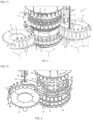
Fig.1 is an isometric partial view of a capping plant which is intended for ring pull caps and the like and to which the invention is applied; -
Fig.2 is a view of the inlet star wheel and capping turret of the plant ofFig. 1 , taken from a different viewpoint; -
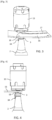
Fig.3 is a schematic lateral view showing the cooperation between a capping head and a guide plate according to the invention, in several steps of a capping operation; -
Fig.4 is a further schematic lateral view showing the cooperation between a capping head and a guide plate according to the invention, in several steps of a capping operation; -
Fig.5 is a further schematic lateral view showing the cooperation between a capping head and a guide plate according to the invention, in several steps of a capping operation; -
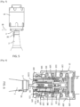
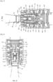
Fig.6 is a sectional view of a capping head in which the invention is used, in several steps of a capping operation; -
Fig.7 is a further sectional view of a capping head in which the invention is used, in several steps of a capping operation; -
Fig.8 is a further sectional view of a capping head in which the invention is used, in several steps of a capping operation. - Referring to
Figs. 1 and 2 , a capping plant has been indicated as a whole with reference numeral 1, said capping plant being intended for applyingcaps 3, which in the described embodiment as illustrated in the figures are caps withring 3A to be pulled for opening, tocontainers 2, especially bottles. As mentioned, the invention, however, is not limited to caps of this type, but it applies also to other types of caps that do not have such ring. - The plant 1 comprises, in a conventional manner:
- a
capping turret 10, hereinafter simply referred to as "capper", which has a plurality ofcapping heads 13, evenly distributed along the circumference thereof and associated each with adrive assembly 19 controlling the axial movements thereof necessary for bringing said capping heads into contact with thecaps 3 and clamp said caps onto thebottles 2; - an
inlet star wheel 11, which feeds thecapper 10 with thebottles 2 to be capped, which bottles, in thecapper 10, will be received onappropriate holders 14 and centered relative to the capping heads by means of centeringmembers 20; and - an outlet star wheel 12, which receives the capped
bottles 2 from thecapper 10 and delivers them to a subsequent working station. - The
capper 10 and the inlet andoutlet star wheels 11, 12 rotate in a mutually synchronous manner, for example in the directions shown by arrows A, B, C inFig. 1 . - During rotation of the
inlet star wheel 11 carrying thebottles 2 towards thecapper 10, thebottles 2 pass by a dispenser or dispensingchannel 15 containing thecaps 3 coming from a feeder (not shown) provided on theturret 10, and take and pull away thecaps 3 by engaging with the inner rim thereof, so that each cap becomes arranged onto the mouth of a respective bottle, onto which it will then by clamped by thecorresponding head 13. - Still in a conventional manner, the plant 1 further comprises a
guide plate 16 extending over thebottles 2 and being substantially parallel to aplatform 11A that carries thebottles 2 into theinlet star wheel 11. The vertical position of theguide plate 16 must be such as not to hinder advancement of thebottles 2, taking into account that a certain height tolerance is provided for them, while at the same time preventing thecaps 3 from slipping off the bottles as a result of vibrations of the plant and/or as a result of gases or foam, in the case of carbonated drinks or foamed drinks such as beer and the like. For example, if the height tolerance is in the order of ± 1,5 mm, theguide plate 16 will be arranged about 2 mm above the nominal height of the bottles. Theguide plate 16 essentially begins at thedispenser 15 and ends in the capping zone, in a point such as to allow thecapping heads 13 to complete their downward axial movement necessary for capping. - Referring also to
Figs. 3-5 , according to the invention, in order to guarantee that thecaps 3 are held in position also after the bottles have moved beyond the end of theguide plate 16, said guide plate has, in its end portion adjacent to thecapper 10, alongitudinal slot 17 open at the end of the guide plate, and thecapping heads 13 have each apressing member 18 formed so as to be able to pass through theslot 17. Theslot 17 begins in a region of the guide plate where acapping head 13, during the capping operation, has moved downward essentially to the height of the guide plate (seeFig. 3 ): more particularly, the initial point of theslot 17 is preferably located slightly before the point of tangency between theinlet star wheel 11 and theturret 10, i.e. the point in which the axis of abottle 2 becomes aligned with the axis of thecapping head 13 and said head starts moving axially downwards in order to perform capping. The pressingmember 18 is associated with elastic control means, described below, which hold it in a position of downward thrust, in which its lower portion protrudes from thecapping head 13, so that, when the rotation of theturret 10 brings thecapping head 13 to theslot 17, said pressing member passes through said slot and comes into contact with thecap 3, as can be seen inFig. 4 . Subsequently, when the cappinghead 13 goes beyond the end of the guide plate 16 (seeFig. 5 ), a further downward movement of the cappinghead 13 causes lifting of the pressingmember 18 upwards, as will be better described in connection with the operation of the system. - Referring to
Figs. 6-8 , there is shown the structure of thecapping head 13 in several steps of a capping operation. In particular, the position shown inFig. 6 corresponds to the one shown inFig. 4 , with thepressing member 18 in contact with thecap 3 but not biased upwards, andFig. 8 shows thecapping head 13 essentially at the end of its axial travel, in its position where it starts clamping thecap 3 onto thebottle 2.Fig. 7 is an intermediate position between the positions ofFigs. 6 and8 . For the sake of simplicity, theguide plate 16 is not shown in said figures. - The
capping head 13 comprises a substantially cylindricalhollow body 100 housing aclamping bell 101 mounted in aguide sleeve 102. The assembly bell 101 -sleeve 102 is kept pressed downwards by aspring 103 arranged between the upper face of thesleeve 102 and the ceiling of thebody 100, and can be moved axially upwards within thebody 100 against the action of thespring 103 during the downward movement of thecapping head 13, after thepressing member 18 has reached thecap 3. Theclamping bell 101 advantageously comprises a plurality of arms arranged circumferentially, as described, for example, in documentUS 4621481 A , said arms having alower end portion 121 which is flared outwards and intended to cooperate with acam 104 having a complementary shape. In the lower end portion of each arm there is further provided atooth 105 which radially projects inwards and is intended to engage the outer lateral surface of thecap 3 in order to deform it and clamp the cap against thebottle 2 when theflared portion 121 of theclamping bell 101, as a result of the upward movement thereof, engages thecam 104. - Inside the
clamping bell 101 there is provided an ejector or pushingmember 106 mounted in aguide sleeve 107 and intended to cooperate with the pressingmember 18 in order to keep thecap 3 pressed against the mouth of thebottle 2 when thecapping head 13 has come into contact therewith (Fig. 7 ). To this aim, theejector 106 is axially biased by aspring 108 arranged between the inner face of ashoulder 109 of thesleeve 107 and anannular flange 110A of the outer surface of ahollow rod 100, described below. Theejector 106, too, is kept pressed downwards by thespring 108 until thepressing member 18 comes into contact with thecap 3, and it can move axially upwards against the action of thespring 18 during further downward movement of thecapping head 13. Thesleeve 107 in turn is kept pushed downwards byBelleville spring washers 115 arranged between an upper portion, substantially bent inwards at a right angle, of the arms of theclamping bell 101 and the upper face of theshoulder 109. As with known capping heads, theBelleville spring washers 115, which have a load higher than that of thespring 103, intervene only in case of irregularities in the shape of the bottle. - The
hollow rod 110 is attached, for example screwed, inside theejector 106 and in arranged to act as a guide for the pressingmember 18 housed within its cavity. Alongitudinal slot 113 formed in the lateral surface of therod 110 acts as a guide for apeg 111 of theejector 106, which peg can be selectively inserted into one of a plurality ofholes 112 vertically aligned on the lateral surface of theguide sleeve 107. Thepeg 111 has the purpose of preventing the assembly rod 110 - ejector 106 - pressingmember 18 to slip off the cappinghead 13 and, by cooperating with theslot 113, limits the travel of theejector 106. The selection of thehole 112 determines the extent by which theejector 106 can protrude downwards from the cappinghead 13, and thus allows adapting the cappinghead 13 to various heights of thebottles 2 to be capped. Ahelical spring 114 arranged inside the cavity of therod 110, between the ceiling thereof and a shoulder of the outer surface of the pressingmember 18, is adapted to keep the pressing member pushed downwards until it comes into contact with thecap 3. - Finally, inside the
body 100 and around theguide sleeve 102 for guiding theclamping bell 101, there is provided afurther spring 120 intended to remove the load from theclamping bell 101 in order to prevent breakage of thebottle 2 in the event that the capping head moves downward beyond the nominal height of the mouth of the bottle. - The operation of the system is as follows.
- When the coordinated rotational movement of the
inlet star wheel 11 and thecapper 10 brings abottle 2 and the cappinghead 13 intended for capping thereof to theslot 17 of theguide plate 16, the cappinghead 13 starts moving downwards so that the pressingmember 18 penetrates through theslot 17 and comes into contact with the cap 3 (Figs. 4 ,6 ). The cappinghead 13, once it has gone beyond the end of theguide plate 16, can go on moving downwards until it is arranged around the mouth of thebottle 2, and by doing so it causes compression of thespring 114 of the pressingmember 18 until said pressing member by moving upwards becomes flush with theejector 106. A further downward movement of the cappinghead 13 now causes compression of thespring 108 of the ejector until the ejector comes into contact with the guiding surface provided at the mouth of itsguide sleeve 109. In this condition, theejector 106 and theguide sleeve 109, too, are essentially in contact with the bottle (Fig. 7 ), and the lower flaredportion 121 of theclamping bell 101 interferes with thecam 104 which pushes inwards the arms of the clamping bell, thereby making theteeth 105 push laterally against the cap, thus causing deformation thereof and effecting closure (Fig. 8 ). It should be noted that, in the condition ofFig. 7 , theteeth 105 do not push against thecap 3 yet, although this cannot be appreciated from the drawing. - It should be noted that, because of the height tolerance for the bottles, the travel of the capping
head 13 is usually adjusted so as to allow capping also of bottles having a height lower than the nominal height, and it is therefore possible that the head moves further downwards beyond the level required for capping a specific bottle. It is then necessary to prevent thecapping head 13 from causing thebottles 2 to explode or break during such further downward movement: this is achieved by thespring 120, which pushes downwards the assembly clamping bell 101 - ejector 106 - pressingmember 18, thus relieving the load applied by the springs 103 - 115 - 108 - 114 and consequently reducing the effort exerted by thehead 13 on thebottle 2. - It is apparent that the above description has been provided solely by way of nonlimiting example and that variations and modifications are possible without departing from the scope of protection of the invention as defined in the appended claims.
- In particular, the
guide rod 110 for the pressingmember 18 can be omitted and the pressing member can be connected directly to theejector 106. In this variant, too, one or more pegs can be provided, equivalent to thepeg 111, and associated directly with theejector 106, in order to prevent the assembly ejector 106 - pressingmember 18 from slipping off the cappinghead 13 and limit the travel of theejector 106. The operation is substantially unchanged with respect to the embodiment shown inFigs. 6-8 .
Claims (9)
- A system for capping containers (2) by means of caps (3) that can be taken and pulled away from a dispenser (15) by the containers themselves, wherein the containers (2) with the caps (3) applied thereon are conveyed from a cap-taking zone to a capping zone where the caps are clamped onto the containers by corresponding capping heads (13), and wherein, along the path of the containers (2) between the cap-taking zone and the capping zone, a guide plate (16) is provided that is located above the containers (2) at such a height that the caps (3) are kept on the containers (2), said guide plate ending at the capping zone in order to allow the capping heads (13) to perform downward axial movements necessary for capping, wherein said guide plate (16) has a longitudinal slot (17) in an end portion thereof adjacent to the capping zone, characterized in that each capping head (13) is equipped with a pressing member (18) shaped so as to be able to pass through the slot (17) and associated with elastic control means (114) that push said pressing member towards the cap (3) on a container (2) through the slot (17) and keep the pressing member in contact with the cap even beyond the end of the guide plate (16), until capping is completed.
- The capping system according to claim 1, wherein the pressing member (18) is mounted inside a hollow guide rod (110) integral for the axial movement with a pushing member (106) intended to cooperate with the pressing member (18) in order to keep a cap (3) pressed against the mouth of the container (2) when the capping head (13) has come into contact with the container, the mounting being such that, because of a downward axial movement of the capping head (13), the pressing member (18), after having come into contact with the cap (3), can axially move upwards in said guiding rod (110) against the action of the control means (114), thereby pushing upwards the guide rod (110) and the pushing member (106).
- The capping system according to claim 1, wherein the pressing member (18) is mounted inside an axial cavity of a pushing member (106) intended to cooperate with the pressing member (18) in order to keep a cap (3) pressed against the mouth of the container (2) when the capping head (13) has come into contact with the container, and is integral with said pushing member (106) for an upward axial movement caused by a downward axial movement of the capping head (13) after the pressing member (18) has come into contact with the cap (3).
- The capping system according to any of the preceding claims, wherein said longitudinal slot (17) begins before a point where the axis of a container (2) becomes aligned with the axis of the capping head (13) and the capping head (13) starts moving downwards, and ends at the end of the plate (16), where it is open.
- The capping system according to any of the preceding claims, wherein the caps (3) preferably are caps with ring (3A) to be pulled for opening.
- A method for capping containers (2) by means of caps (3) that can be taken and pulled away from a dispenser (15) by the containers themselves, comprising the steps of:- conveying the containers (2), after they have taken the caps, from the cap-taking zone to a capping zone where the caps (3) are clamped onto the containers by respective capping heads (13); and- guiding the containers (2), along the path of the containers (2) between the cap-taking zone and the capping zone, by means of a guide plate (16) that is located above the containers (2) at such a height that the caps (3) are kept on the containers themselves, the guide plate (16) ending at the capping zone in order to allow the capping heads (13) to perform downward axial movements necessary for capping,wherein the step of guiding the containers (2) is performed by means of a guide plate (16) having a longitudinal slot (17) in an end portion thereof adjacent to the capping zone, characterized in that the method further includes the steps of:- equipping each capping head (13) with a pressing member (18) intended to engage the cap (3) by passing through the slot (17); and- controlling the pressing member (18) by means of elastic control means (114) that push the pressing member towards the cap (3) on a container (2) through the slot (17) and keep the pressing member in contact with the cap (3) even after the container has moved beyond the guide plate (16), until capping is completed.
- The method according to claim 6, wherein the step of equipping each capping head (13) with a pressing member (18) comprises mounting the pressing member (18) inside a hollow guide rod (110) integral for the axial movement with a pushing member (106) intended to cooperate with the pressing member (18) in order to keep a cap (3) pressed against the mouth of the container (2) when the capping head (13) has come into contact with the container, the mounting being such that the pressing member (18), after having come into contact with the cap (3), can axially move upwards in said guide rod (110) against the action of the control means (114) because of a downward axial movement of the capping head (13).
- The method according to claim 6, wherein the step of equipping each capping head (13) with a pressing member (18) comprises mounting the pressing member (18) inside an axial cavity of a pushing member (106) intended to cooperate with the pressing member (18) in order to keep a cap (3) pressed against the mouth of the container (2) when the capping head (13) has come into contact with the container, the mounting being such that the pressing member (18) is integral with said pushing member (106) for the upward axial movement caused by a downward axial movement of the capping head (13), after the pressing member (18) has come into contact with the cap (3).
- The method according to any of claims 6 to 8, for capping containers (2) preferably by means of caps (3) with ring (3A) to be pulled for opening.
Applications Claiming Priority (2)
| Application Number | Priority Date | Filing Date | Title |
|---|---|---|---|
| IT202100003218 | 2021-02-12 | ||
| PCT/IB2022/051227 WO2022172207A1 (en) | 2021-02-12 | 2022-02-11 | System and method for capping containers |
Publications (3)
| Publication Number | Publication Date |
|---|---|
| EP4284750A1 EP4284750A1 (en) | 2023-12-06 |
| EP4284750C0 EP4284750C0 (en) | 2025-03-12 |
| EP4284750B1 true EP4284750B1 (en) | 2025-03-12 |
Family
ID=75769749
Family Applications (1)
| Application Number | Title | Priority Date | Filing Date |
|---|---|---|---|
| EP22708604.8A Active EP4284750B1 (en) | 2021-02-12 | 2022-02-11 | System and method for capping containers |
Country Status (3)
| Country | Link |
|---|---|
| EP (1) | EP4284750B1 (en) |
| ES (1) | ES3029859T3 (en) |
| WO (1) | WO2022172207A1 (en) |
Families Citing this family (2)
| Publication number | Priority date | Publication date | Assignee | Title |
|---|---|---|---|---|
| IT202200018609A1 (en) * | 2022-09-12 | 2024-03-12 | Arol Spa | Closing group for capping head of a capping machine |
| IT202200018603A1 (en) * | 2022-09-12 | 2024-03-12 | Arol Spa | Closing group for capping head for capping machine and capping machine |
Family Cites Families (3)
| Publication number | Priority date | Publication date | Assignee | Title |
|---|---|---|---|---|
| US2647672A (en) * | 1946-02-11 | 1953-08-04 | Crown Cork Specialty Corp | Cap applying apparatus |
| US4295320A (en) * | 1980-01-09 | 1981-10-20 | Owens-Illinois, Inc. | Closure conversion apparatus for existing closure applicating machines |
| JP6598767B2 (en) * | 2014-04-15 | 2019-10-30 | 日本クロージャー株式会社 | Sealed container for positive pressure beverage and method for producing the same |
-
2022
- 2022-02-11 ES ES22708604T patent/ES3029859T3/en active Active
- 2022-02-11 EP EP22708604.8A patent/EP4284750B1/en active Active
- 2022-02-11 WO PCT/IB2022/051227 patent/WO2022172207A1/en not_active Ceased
Also Published As
| Publication number | Publication date |
|---|---|
| EP4284750A1 (en) | 2023-12-06 |
| WO2022172207A1 (en) | 2022-08-18 |
| EP4284750C0 (en) | 2025-03-12 |
| ES3029859T3 (en) | 2025-06-25 |
Similar Documents
| Publication | Publication Date | Title |
|---|---|---|
| CN111977597B (en) | Device for holding a container and closure device | |
| WO2022172207A1 (en) | System and method for capping containers | |
| US4624098A (en) | Container restraint system | |
| EP0636573B1 (en) | Capping unit for automatically assembling pump-operated spray cap bottles | |
| US5473855A (en) | System for installing closures on containers | |
| US4663913A (en) | Closure application system | |
| EP3199490B1 (en) | Receptacle handling apparatus for filling and capping receptacles | |
| EP2439168A1 (en) | Machine for application of caps on containers such as bottles and the like | |
| CA2091720A1 (en) | Method and apparatus for closing bottles | |
| EP0248083A4 (en) | Filling valve for counterpressure filling of cans. | |
| US5934042A (en) | Anti-rotation wear plate for capping machine | |
| EP1041034A3 (en) | Grippers for plastic bottles | |
| US5012630A (en) | Closure application system | |
| EP0701966B1 (en) | A beverage packaging apparatus and a beverage packaging method | |
| EP0403259A1 (en) | Capping and de-capping of plastic bottles | |
| EP3453629A1 (en) | Method and machine for filling and capping receptacles | |
| CN110603222B (en) | Device for gripping and centering bottles for capping machines | |
| US5544551A (en) | Device to draw mushroom-shaped corks | |
| JP6492684B2 (en) | Capping head and capper | |
| US3434266A (en) | Cap crimping apparatus | |
| US5457936A (en) | Cap tightening turret | |
| EP3826945B1 (en) | Neck guiding device for bottling lines | |
| EP0775667B1 (en) | Capping apparatus | |
| US20080314857A1 (en) | Bottle Closure System and Cap That Can be Incorporated in Said Closure | |
| US6374576B1 (en) | Capping method and capping apparatus, in particular for capping containers with crown caps |
Legal Events
| Date | Code | Title | Description |
|---|---|---|---|
| STAA | Information on the status of an ep patent application or granted ep patent |
Free format text: STATUS: UNKNOWN |
|
| STAA | Information on the status of an ep patent application or granted ep patent |
Free format text: STATUS: THE INTERNATIONAL PUBLICATION HAS BEEN MADE |
|
| PUAI | Public reference made under article 153(3) epc to a published international application that has entered the european phase |
Free format text: ORIGINAL CODE: 0009012 |
|
| STAA | Information on the status of an ep patent application or granted ep patent |
Free format text: STATUS: REQUEST FOR EXAMINATION WAS MADE |
|
| 17P | Request for examination filed |
Effective date: 20230829 |
|
| AK | Designated contracting states |
Kind code of ref document: A1 Designated state(s): AL AT BE BG CH CY CZ DE DK EE ES FI FR GB GR HR HU IE IS IT LI LT LU LV MC MK MT NL NO PL PT RO RS SE SI SK SM TR |
|
| DAV | Request for validation of the european patent (deleted) | ||
| DAX | Request for extension of the european patent (deleted) | ||
| GRAP | Despatch of communication of intention to grant a patent |
Free format text: ORIGINAL CODE: EPIDOSNIGR1 |
|
| STAA | Information on the status of an ep patent application or granted ep patent |
Free format text: STATUS: GRANT OF PATENT IS INTENDED |
|
| INTG | Intention to grant announced |
Effective date: 20240927 |
|
| GRAS | Grant fee paid |
Free format text: ORIGINAL CODE: EPIDOSNIGR3 |
|
| GRAA | (expected) grant |
Free format text: ORIGINAL CODE: 0009210 |
|
| STAA | Information on the status of an ep patent application or granted ep patent |
Free format text: STATUS: THE PATENT HAS BEEN GRANTED |
|
| AK | Designated contracting states |
Kind code of ref document: B1 Designated state(s): AL AT BE BG CH CY CZ DE DK EE ES FI FR GB GR HR HU IE IS IT LI LT LU LV MC MK MT NL NO PL PT RO RS SE SI SK SM TR |
|
| REG | Reference to a national code |
Ref country code: GB Ref legal event code: FG4D |
|
| REG | Reference to a national code |
Ref country code: CH Ref legal event code: EP |
|
| REG | Reference to a national code |
Ref country code: DE Ref legal event code: R096 Ref document number: 602022011715 Country of ref document: DE |
|
| REG | Reference to a national code |
Ref country code: IE Ref legal event code: FG4D |
|
| U01 | Request for unitary effect filed |
Effective date: 20250410 |
|
| U07 | Unitary effect registered |
Designated state(s): AT BE BG DE DK EE FI FR IT LT LU LV MT NL PT RO SE SI Effective date: 20250417 |
|
| REG | Reference to a national code |
Ref country code: ES Ref legal event code: FG2A Ref document number: 3029859 Country of ref document: ES Kind code of ref document: T3 Effective date: 20250625 |
|
| PG25 | Lapsed in a contracting state [announced via postgrant information from national office to epo] |
Ref country code: RS Free format text: LAPSE BECAUSE OF FAILURE TO SUBMIT A TRANSLATION OF THE DESCRIPTION OR TO PAY THE FEE WITHIN THE PRESCRIBED TIME-LIMIT Effective date: 20250612 |
|
| PG25 | Lapsed in a contracting state [announced via postgrant information from national office to epo] |
Ref country code: NO Free format text: LAPSE BECAUSE OF FAILURE TO SUBMIT A TRANSLATION OF THE DESCRIPTION OR TO PAY THE FEE WITHIN THE PRESCRIBED TIME-LIMIT Effective date: 20250612 |
|
| PG25 | Lapsed in a contracting state [announced via postgrant information from national office to epo] |
Ref country code: HR Free format text: LAPSE BECAUSE OF FAILURE TO SUBMIT A TRANSLATION OF THE DESCRIPTION OR TO PAY THE FEE WITHIN THE PRESCRIBED TIME-LIMIT Effective date: 20250312 |
|
| PG25 | Lapsed in a contracting state [announced via postgrant information from national office to epo] |
Ref country code: GR Free format text: LAPSE BECAUSE OF FAILURE TO SUBMIT A TRANSLATION OF THE DESCRIPTION OR TO PAY THE FEE WITHIN THE PRESCRIBED TIME-LIMIT Effective date: 20250613 |
|
| PG25 | Lapsed in a contracting state [announced via postgrant information from national office to epo] |
Ref country code: SM Free format text: LAPSE BECAUSE OF FAILURE TO SUBMIT A TRANSLATION OF THE DESCRIPTION OR TO PAY THE FEE WITHIN THE PRESCRIBED TIME-LIMIT Effective date: 20250312 |
|
| PG25 | Lapsed in a contracting state [announced via postgrant information from national office to epo] |
Ref country code: PL Free format text: LAPSE BECAUSE OF FAILURE TO SUBMIT A TRANSLATION OF THE DESCRIPTION OR TO PAY THE FEE WITHIN THE PRESCRIBED TIME-LIMIT Effective date: 20250312 |
|
| PG25 | Lapsed in a contracting state [announced via postgrant information from national office to epo] |
Ref country code: CZ Free format text: LAPSE BECAUSE OF FAILURE TO SUBMIT A TRANSLATION OF THE DESCRIPTION OR TO PAY THE FEE WITHIN THE PRESCRIBED TIME-LIMIT Effective date: 20250312 |
|
| PG25 | Lapsed in a contracting state [announced via postgrant information from national office to epo] |
Ref country code: SK Free format text: LAPSE BECAUSE OF FAILURE TO SUBMIT A TRANSLATION OF THE DESCRIPTION OR TO PAY THE FEE WITHIN THE PRESCRIBED TIME-LIMIT Effective date: 20250312 |
|
| PG25 | Lapsed in a contracting state [announced via postgrant information from national office to epo] |
Ref country code: IS Free format text: LAPSE BECAUSE OF FAILURE TO SUBMIT A TRANSLATION OF THE DESCRIPTION OR TO PAY THE FEE WITHIN THE PRESCRIBED TIME-LIMIT Effective date: 20250712 |
|
| PLBE | No opposition filed within time limit |
Free format text: ORIGINAL CODE: 0009261 |
|
| STAA | Information on the status of an ep patent application or granted ep patent |
Free format text: STATUS: NO OPPOSITION FILED WITHIN TIME LIMIT |
|
| REG | Reference to a national code |
Ref country code: CH Ref legal event code: L10 Free format text: ST27 STATUS EVENT CODE: U-0-0-L10-L00 (AS PROVIDED BY THE NATIONAL OFFICE) Effective date: 20260121 |
|
| 26N | No opposition filed |
Effective date: 20251215 |
|
| U20 | Renewal fee for the european patent with unitary effect paid |
Year of fee payment: 5 Effective date: 20260219 |