EP4284122A1 - Monitoring device - Google Patents
Monitoring device Download PDFInfo
- Publication number
- EP4284122A1 EP4284122A1 EP21921186.9A EP21921186A EP4284122A1 EP 4284122 A1 EP4284122 A1 EP 4284122A1 EP 21921186 A EP21921186 A EP 21921186A EP 4284122 A1 EP4284122 A1 EP 4284122A1
- Authority
- EP
- European Patent Office
- Prior art keywords
- monitoring device
- electrode
- cover
- plasma
- attachment
- Prior art date
- Legal status (The legal status is an assumption and is not a legal conclusion. Google has not performed a legal analysis and makes no representation as to the accuracy of the status listed.)
- Pending
Links
- 238000012806 monitoring device Methods 0.000 title claims abstract description 222
- 239000000428 dust Substances 0.000 claims abstract description 60
- 230000004888 barrier function Effects 0.000 claims abstract description 52
- 238000012544 monitoring process Methods 0.000 claims description 4
- 230000004308 accommodation Effects 0.000 description 24
- 239000011521 glass Substances 0.000 description 20
- 229910052594 sapphire Inorganic materials 0.000 description 20
- 239000010980 sapphire Substances 0.000 description 20
- 239000000919 ceramic Substances 0.000 description 17
- 230000000694 effects Effects 0.000 description 13
- 238000009413 insulation Methods 0.000 description 13
- 239000003570 air Substances 0.000 description 11
- 238000007789 sealing Methods 0.000 description 9
- 238000000034 method Methods 0.000 description 7
- 239000000463 material Substances 0.000 description 6
- 239000002184 metal Substances 0.000 description 6
- 239000012080 ambient air Substances 0.000 description 5
- 239000012212 insulator Substances 0.000 description 5
- 238000012423 maintenance Methods 0.000 description 4
- 238000004519 manufacturing process Methods 0.000 description 4
- 238000002485 combustion reaction Methods 0.000 description 3
- 230000002093 peripheral effect Effects 0.000 description 3
- 230000002265 prevention Effects 0.000 description 3
- 238000007664 blowing Methods 0.000 description 2
- VYPSYNLAJGMNEJ-UHFFFAOYSA-N Silicium dioxide Chemical compound O=[Si]=O VYPSYNLAJGMNEJ-UHFFFAOYSA-N 0.000 description 1
- 230000001464 adherent effect Effects 0.000 description 1
- 239000011248 coating agent Substances 0.000 description 1
- 238000000576 coating method Methods 0.000 description 1
- 239000000356 contaminant Substances 0.000 description 1
- 238000001816 cooling Methods 0.000 description 1
- 230000005684 electric field Effects 0.000 description 1
- 230000008020 evaporation Effects 0.000 description 1
- 238000001704 evaporation Methods 0.000 description 1
- 239000010881 fly ash Substances 0.000 description 1
- 238000002844 melting Methods 0.000 description 1
- 230000008018 melting Effects 0.000 description 1
- 239000002245 particle Substances 0.000 description 1
- 239000002699 waste material Substances 0.000 description 1
Images





Classifications
-
- F—MECHANICAL ENGINEERING; LIGHTING; HEATING; WEAPONS; BLASTING
- F23—COMBUSTION APPARATUS; COMBUSTION PROCESSES
- F23M—CASINGS, LININGS, WALLS OR DOORS SPECIALLY ADAPTED FOR COMBUSTION CHAMBERS, e.g. FIREBRIDGES; DEVICES FOR DEFLECTING AIR, FLAMES OR COMBUSTION PRODUCTS IN COMBUSTION CHAMBERS; SAFETY ARRANGEMENTS SPECIALLY ADAPTED FOR COMBUSTION APPARATUS; DETAILS OF COMBUSTION CHAMBERS, NOT OTHERWISE PROVIDED FOR
- F23M11/00—Safety arrangements
- F23M11/04—Means for supervising combustion, e.g. windows
-
- F—MECHANICAL ENGINEERING; LIGHTING; HEATING; WEAPONS; BLASTING
- F23—COMBUSTION APPARATUS; COMBUSTION PROCESSES
- F23N—REGULATING OR CONTROLLING COMBUSTION
- F23N5/00—Systems for controlling combustion
- F23N5/02—Systems for controlling combustion using devices responsive to thermal changes or to thermal expansion of a medium
- F23N5/08—Systems for controlling combustion using devices responsive to thermal changes or to thermal expansion of a medium using light-sensitive elements
- F23N5/082—Systems for controlling combustion using devices responsive to thermal changes or to thermal expansion of a medium using light-sensitive elements using electronic means
-
- H—ELECTRICITY
- H05—ELECTRIC TECHNIQUES NOT OTHERWISE PROVIDED FOR
- H05H—PLASMA TECHNIQUE; PRODUCTION OF ACCELERATED ELECTRICALLY-CHARGED PARTICLES OR OF NEUTRONS; PRODUCTION OR ACCELERATION OF NEUTRAL MOLECULAR OR ATOMIC BEAMS
- H05H1/00—Generating plasma; Handling plasma
- H05H1/24—Generating plasma
- H05H1/2406—Generating plasma using dielectric barrier discharges, i.e. with a dielectric interposed between the electrodes
-
- F—MECHANICAL ENGINEERING; LIGHTING; HEATING; WEAPONS; BLASTING
- F23—COMBUSTION APPARATUS; COMBUSTION PROCESSES
- F23N—REGULATING OR CONTROLLING COMBUSTION
- F23N2229/00—Flame sensors
- F23N2229/18—Flame sensor cooling means
-
- F—MECHANICAL ENGINEERING; LIGHTING; HEATING; WEAPONS; BLASTING
- F23—COMBUSTION APPARATUS; COMBUSTION PROCESSES
- F23N—REGULATING OR CONTROLLING COMBUSTION
- F23N2229/00—Flame sensors
- F23N2229/20—Camera viewing
-
- H—ELECTRICITY
- H04—ELECTRIC COMMUNICATION TECHNIQUE
- H04N—PICTORIAL COMMUNICATION, e.g. TELEVISION
- H04N23/00—Cameras or camera modules comprising electronic image sensors; Control thereof
- H04N23/50—Constructional details
- H04N23/52—Elements optimising image sensor operation, e.g. for electromagnetic interference [EMI] protection or temperature control by heat transfer or cooling elements
-
- H—ELECTRICITY
- H04—ELECTRIC COMMUNICATION TECHNIQUE
- H04N—PICTORIAL COMMUNICATION, e.g. TELEVISION
- H04N7/00—Television systems
- H04N7/18—Closed-circuit television [CCTV] systems, i.e. systems in which the video signal is not broadcast
- H04N7/183—Closed-circuit television [CCTV] systems, i.e. systems in which the video signal is not broadcast for receiving images from a single remote source
- H04N7/185—Closed-circuit television [CCTV] systems, i.e. systems in which the video signal is not broadcast for receiving images from a single remote source from a mobile camera, e.g. for remote control
-
- H—ELECTRICITY
- H05—ELECTRIC TECHNIQUES NOT OTHERWISE PROVIDED FOR
- H05H—PLASMA TECHNIQUE; PRODUCTION OF ACCELERATED ELECTRICALLY-CHARGED PARTICLES OR OF NEUTRONS; PRODUCTION OR ACCELERATION OF NEUTRAL MOLECULAR OR ATOMIC BEAMS
- H05H1/00—Generating plasma; Handling plasma
- H05H1/24—Generating plasma
- H05H1/2406—Generating plasma using dielectric barrier discharges, i.e. with a dielectric interposed between the electrodes
- H05H1/2437—Multilayer systems
-
- H—ELECTRICITY
- H05—ELECTRIC TECHNIQUES NOT OTHERWISE PROVIDED FOR
- H05H—PLASMA TECHNIQUE; PRODUCTION OF ACCELERATED ELECTRICALLY-CHARGED PARTICLES OR OF NEUTRONS; PRODUCTION OR ACCELERATION OF NEUTRAL MOLECULAR OR ATOMIC BEAMS
- H05H1/00—Generating plasma; Handling plasma
- H05H1/24—Generating plasma
- H05H1/2406—Generating plasma using dielectric barrier discharges, i.e. with a dielectric interposed between the electrodes
- H05H1/2439—Surface discharges, e.g. air flow control
-
- H—ELECTRICITY
- H05—ELECTRIC TECHNIQUES NOT OTHERWISE PROVIDED FOR
- H05H—PLASMA TECHNIQUE; PRODUCTION OF ACCELERATED ELECTRICALLY-CHARGED PARTICLES OR OF NEUTRONS; PRODUCTION OR ACCELERATION OF NEUTRAL MOLECULAR OR ATOMIC BEAMS
- H05H1/00—Generating plasma; Handling plasma
- H05H1/24—Generating plasma
- H05H1/2406—Generating plasma using dielectric barrier discharges, i.e. with a dielectric interposed between the electrodes
- H05H1/2443—Generating plasma using dielectric barrier discharges, i.e. with a dielectric interposed between the electrodes the plasma fluid flowing through a dielectric tube
- H05H1/2465—Generating plasma using dielectric barrier discharges, i.e. with a dielectric interposed between the electrodes the plasma fluid flowing through a dielectric tube the plasma being activated by inductive coupling, e.g. using coiled electrodes
Definitions
- the present invention relates to a monitoring device, more specifically a monitoring device for monitoring an inside of a furnace.
- a combustion furnace in a waste-to-energy plant or the like is provided with a monitoring device for monitoring a state of an inside of the furnace.
- This type of monitoring device suffers adherence of dust (contaminant) to a lens and the like as a result of combustion.
- a technique for preventing adherence of dust or removal of dust has therefore been proposed.
- Patent Literature 1 discloses a technique of releasing a dust prevention gas toward a tip part side of a lens tube.
- Patent Literature 2 discloses a technique of attaching, to a tip part side of a lens tube, a rotatable transparent body with blades (propeller mechanism).
- Patent Literature 1 cannot sufficiently prevent adherence of dust and requires periodical removal (blowing off) of dust by hand. Furthermore, there may be dust that cannot be removed even by hand (for example, dust that has entered an inner circumferential part of an opening) and causes a partial loss of the field of view of a captured image.
- Patent Literature 2 has problems caused by the addition of the propeller mechanism, such as that maintenance of the propeller mechanism is required and that the propeller mechanism undesirably appears in an image captured by a camera. These problems make it difficult to apply the technique of Patent Literature 2.
- a monitoring device in accordance with an aspect of the present invention is a monitoring device for monitoring an inside of a furnace, including: a light guide part guiding light from the inside of the furnace to a camera; a cover having a tubular shape, covering a circumferential surface of the light guide part, and having, in a tip part of the cover on a side of the inside of the furnace, an opening that lets light pass therethrough; and a plasma actuator including a first electrode that generates, toward a center axis of the cover, at least one of (i) a plasma generated by a dielectric barrier discharge and (ii) a jet flow induced due to the plasma, the plasma actuator removing, with use of at least one of the plasma and the jet flow, dust adhering to a surface of the monitoring device which surface faces the inside of the furnace or to an inside of the monitoring device.
- An aspect of the present invention makes it possible to provide a monitoring device in which narrowing of a field of view due to adherence of dust can be improved without frequent maintenance.
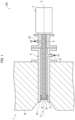
- FIG. 1 is a cross-sectional view illustrating a state in which the monitoring device 100 in accordance with Embodiment 1 is attached to a furnace 1.
- a side (left side in Fig. 1 ) facing an inside 11 of the furnace 1 may be referred to as a tip part side
- a side (right side in Fig. 1 ) opposite to the tip part side may be referred to as a base end part side.
- the furnace 1 illustrated in Fig. 1 is, for example, a combustion furnace or a melting furnace, and the inside 11 of the furnace is exposed to a high-temperature atmosphere.
- the monitoring device 100 is attached to a furnace wall 12, which is a side wall, an upper wall, or the like of the furnace 1, in order to monitor the state of the inside 11 of the furnace.
- a tubular mounting tool 2 is provided in a mounting hole 13 formed in a thickness direction of the furnace wall 12, and a tip part side of the monitoring device 100 is inserted into the mounting hole 13 via the mounting tool 2.
- the mounting tool 2 has formed therein a first vent 21 for introducing first sealing air A1 for dust prevention into an inside of the mounting tool 2 is formed in the mounting tool 2.
- the first sealing air A1 introduced from the first vent 21 flows, from the base end part side toward the tip part side, through a gap between an outer circumferential surface of a cover 5 of the monitoring device 100 and an inner circumferential surface of the mounting tool 2 and is discharged from a tip part side of the mounting tool 2.
- the introduction of the first sealing air A1 into the inside of the mounting tool 2 prevents dust generated in the inside 11 of the furnace from adhering to a surface of the monitoring device 100 which surface faces the inside 11 of the furnace.
- the introduction also cools the cover 5 and thus prevents an excessive increase in temperature of the lens (light guide part) 4.
- the monitoring device 100 includes a camera 3, the lens 4 which guides light from the inside 11 of the furnace to the camera 3, the tubular cover 5 which covers an outer circumferential surface (circumferential surface) of the lens 4, and an attachment 6 on which a plasma actuator to be described later is mounted.
- the camera 3 is connected to a base end part side of the lens 4 and captures an image of a state of the inside 11 of the furnace on the basis of the light guided by the lens 4.
- a CCD camera or the like is used as the camera 3, for example.
- the lens 4 and the cover 5 are disposed such that respective center axes C coincide with each other.
- An opening 51 which lets light pass therethrough is formed at a tip part of the cover 5.
- the attachment 6 is detachably attached to the tip part of the cover 5 so as to surround a periphery of the opening 51 of the cover 5.
- the monitoring device 100 has formed therein a second vent 52 for introducing second sealing air A2 for dust prevention into an inside of the cover 5.
- the second sealing air A2 introduced from the second vent 52 flows through a gap between the outer circumferential surface of the lens 4 and an inner circumferential surface of the cover 5 from the base end part side toward the tip part side, and is discharged from the opening 51 formed in the tip part of the cover 5.
- the second sealing air A2 prevents dust generated in the inside 11 of the furnace from adhering to the surface of the monitoring device 100 which surface faces the inside 11 of the furnace, and also prevents an excessive increase in temperature of the lens 4 by cooling the lens 4.
- the monitoring device 100 uses the first sealing air A1 and the second sealing air A2 to prevent dust generated in the inside 11 of the furnace from adhering to the monitoring device 100.
- adherence of dust cannot be completely prevented, and dust may adhere to the surface of the monitoring device 100 which surface faces the inside 11 of the furnace.
- dust adheres to the monitoring device 100 a part of the field of view of an image captured by the camera 3 may be lost. This makes it difficult to properly monitor the state of the inside 11 of the furnace.
- the monitoring device 100 includes the plasma actuator and removes dust adhering to the monitoring device 100 with use of a dielectric barrier discharge (DBD) by the plasma actuator to improve narrowing of the field of view caused by adherence of dust.
- DBD dielectric barrier discharge
- the monitoring device 100 is attached to the furnace wall 12 at an angle at which the center axis C vertically intersects with the furnace wall 12 of the furnace 1. Note that the monitoring device 100 can be attached to the furnace wall 12 at an angle at which the center axis C obliquely intersects with the furnace wall 12.
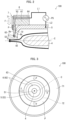
- Fig. 2 is a cross section showing a main part of the monitoring device 100 illustrated in Fig. 1 .
- Fig. 3 is a front view of the monitoring device 100 illustrated in Fig. 1 , which front view is obtained when the monitoring device 100 is viewed from the tip part side.
- the monitoring device 100 is configured such that the attachment 6 is mounted on the tip part side of the cover 5 covering the outer circumferential surface of the lens 4.
- a first electrode 71 and a second electrode 72 of a plasma actuator 7 are disposed on the attachment 6.
- the lens 4 is a substantially cylindrical lens tube.
- the lens 4 has a function of adjusting a focal position of light so that a clear image can be captured by the camera 3.
- the lens 4 may be, for example, constituted by a plurality of lenses combined together.
- the cover 5 is an electrically conductive tubular member.
- the cover 5 is made of, for example, a metal tube such as SUS.
- the cover 5 is disposed so as to cover a substantially entire length of the lens 4 from a tip part side of the lens 4 to a base end part side of the lens 4.
- the tip part of the cover 5 curvilinearly bends toward the center axis C.
- a circular opening 51 having a center on the center axis C is formed in the tip part.
- the opening 51 is formed to have a smaller diameter than an inner diameter of the cover 5. In a case where an opening area of the opening 51 is thus relatively reduced, dust D generated in the inside 11 of the furnace is less likely to infiltrate the inside of the cover 5 through the opening 51.
- an inclined surface 53 which is inclined toward the base end part side with respect to the center axis C is formed.
- the attachment 6 is a mounting tool for attaching the plasma actuator 7 to the cover 5.
- the attachment 6 is made of a dielectric (insulator).
- the dielectric (insulator) include machinable ceramics, high temperature co-fired ceramics (HTCC), low temperature co-fired ceramics (LTCC), a stacked package thereof, and sapphire glass.
- the attachment 6 is constituted by the following two members: a cylindrical tubular part 61 which fits on the outer circumferential surface of the cover 5; and a disk-shaped tip wall 62 which is provided on a tip part side of the tubular part 61.
- the tip wall 62 has formed therein a circular opening 63 having a center on the center axis C.
- the opening 63 of the attachment 6 is formed to have a diameter larger than that of the opening 51 of the cover 5 so that the inclined surface 53 of the cover 5 is exposed at a tip part of the monitoring device 100. Light from the inside 11 of the furnace passes through the opening 63 of the attachment 6 and the opening 51 of the cover 5 and enters the lens 4.
- the plasma actuator 7 is a device that generates a plasma P and an induced jet flow (jet flow) F by a dielectric barrier discharge.
- the plasma actuator 7 includes the first electrode 71 and the second electrode 72.
- Each of the first electrode 71 and the second electrode 72 has an annular shape (ring shape) and is disposed to have a center on the center axis C.
- the first electrode 71 is formed to have a diameter larger than that of the second electrode 72, and an inner diameter of the first electrode 71 is substantially equal to an outer diameter of the second electrode 72.
- the first electrode 71 and the second electrode 72 can each have one or more gaps formed in part thereof. In a case where, for example, a plurality of gaps separate each electrode into segments, maintaining the segments to be at the same electric potential allows forming electrodes that are disposed in an annular shape as a whole. Segmenting each electrode in this way provides, for example, the following remarkable effect. That is, by disposing each electrode such that the respective positions of the gaps are displaced from each other at a constant angle in a circumferential direction of the center axis C, it is possible to generate an induced jet flow F swirling around the center axis C.
- the first electrode 71 and the second electrode 72 are each not limited to a circular annular shape.
- the first electrode 71 and the second electrode 72 may each have an annular shape other than a circular shape, such as a polygonal shape, for example.
- the first electrode 71 and the second electrode 72 are disposed with the tip wall 62 of the attachment 6 interposed therebetween.
- the first electrode 71 is disposed on a front surface 6a of the tip wall 62 of the attachment 6, which front surface 6a is on the tip part side of the tip wall 62.
- the first electrode 71 may be disposed such that all or part of the first electrode 71 is embedded in the attachment 6.
- the second electrode 72 is disposed on a back surface 6b of the tip wall 62 of the attachment 6, which back surface 6b is on a base end part side (side opposite to the front surface 6a) of the tip wall 62. More specifically, in a gap formed between the cover 5 and the attachment 6, the second electrode 72 is disposed on the back surface 6b while being in contact with the tip part of the cover 5.
- the first electrode 71 and the second electrode 72 are electrically connected to an AC power supply PS.
- the AC power supply PS is a power supply capable of outputting a high voltage having, for example, a sine waveform or a pulse waveform at a high frequency.
- the first electrode 71 is electrically connected to the AC power supply PS via a first wire L1.
- the first wire L1 has one end connected to the AC power supply PS and the other end connected to the first electrode 71 through a through hole 64 for wiring formed in the attachment 6.
- the second electrode 72 is electrically connected to the AC power supply PS via the electrically conductive cover 5 and a second wire L2.
- the second wire L2 has one end connected to the AC power supply PS and the other end connected to the electrically conductive cover 5.
- the attachment 6 has formed therein the through hole 64 through which the first wire L1 is passed.
- the other end of the first wire L1 may be connected to the first electrode 71 through an outside of the attachment 6 so that the first electrode 71 and the AC power supply PS are electrically connected to each other.
- the plasma actuator 7 has the annular first electrode 71 and the annular second electrode 72 disposed in the manner described above such that the tip wall 62 of the attachment 6 made of a dielectric is interposed between the first electrode 71 and the second electrode 72.
- a dielectric barrier discharge is generated along the front surface 6a of the attachment 6. This causes a plasma P to be generated in the vicinity of an inner diameter side edge of the annular first electrode 71. Further, charged particles resulting from the production of the plasma P are accelerated by an electric field, and ambient air is induced, so that an induced jet flow F toward the center axis C is generated.
- the plasma actuator 7 removes dust D adhering to the monitoring device 100, with use of at least one of a plasma P caused by a dielectric barrier discharge and an induced jet flow F.
- the plasma actuator 7 breaks down dust D adhering to the monitoring device 100, with use of a plasma P caused by a dielectric barrier discharge.
- the plasma actuator 7 also scatters dust D adhering to the monitoring device 100, with use of an induced jet flow F caused by a dielectric barrier discharge.
- the plasma actuator 7 breaks down and scatters dust D adhering to the monitoring device 100, with use of both a plasma P caused by a dielectric barrier discharge and an induced jet flow F.
- the plasma actuator 7 makes it possible to remove dust D that cannot be dealt with conventionally and thus to improve narrowing of the field of view of the monitoring device 100 caused by adherence of the dust D.
- the attachment 6 made of a dielectric is constituted by the following two members: the tubular part 61 and the tip wall 62.
- the attachment 6 may consist of a single member in which the tubular part 61 and the tip wall 62 are integrally formed.
- the tubular part 61 may be made of a material other than a dielectric having a high insulation property. This makes it possible to reduce the manufacturing cost of the attachment 6.
- the monitoring device 100 may control the plasma actuator 7 to generate a dielectric barrier discharge continuously or intermittently.
- the monitoring device 100 may also generate a dielectric barrier discharge in accordance with a state of dust D adherence, an amount of dust D generated, or the like.
- the monitoring device 100 may process an image captured by the camera 3 and, in a case where it is determined from the captured image that there is adherent dust D, generate a dielectric barrier discharge.
- the monitoring device 100 may also detect, with use of a sensor, an amount of waste introduced to the furnace 1, a speed of a grate, an evaporation amount, and/or the like, and generate a dielectric barrier discharge by predicting an amount of fly ash generated in accordance with value(s) thus detected.
- the monitoring device 100 may adjust an intensity of an electric current of the dielectric barrier discharge, a frequency of the dielectric barrier discharge, and/or a direction of an air stream (induced jet flow F) in accordance with a degree of adherence of dust D and/or a position to which dust D is adhering.
- the monitoring device 100 may include a plurality of first electrodes 71 so as to maximize an induced jet flow F, and a timing of generating an electric barrier discharge may be adjusted.
- the monitoring device 100 in accordance with Embodiment 1 includes: the lens 4 guiding light from the inside 11 of the furnace to the camera 3; the cover 5 having a tubular shape, covering the outer circumferential surface of the lens 4, and having, in the tip part of the cover 5 on the side of the inside 11 of the furnace, the opening 51 that lets light pass therethrough; and the plasma actuator 7 including the first electrode 71 that generates, toward the center axis C of the cover 5, at least one of (i) a plasma P generated by a dielectric barrier discharge and (ii) an induced jet flow F induced due to the plasma P, the plasma actuator 7 removing, with use of at least one of the plasma P and the induced jet flow F, dust D adhering to the surface of the monitoring device 100 which surface faces the inside 11 of the furnace.
- the monitoring device 100 Since dust D adhering to the monitoring device 100 is removed by a dielectric barrier discharge, the monitoring device 100 makes it possible to remove dust D that cannot conventionally be handled. As such, in accordance with Embodiment 1, it is possible to provide the monitoring device 100 in which narrowing of the field of view due to adherence of dust D can be improved without frequent maintenance.
- the monitoring device 100 is preferably configured such that the first electrode 71 is disposed at the opening 51 of the cover 5 or at a side closer to the inside 11 of the furnace than the opening 51. This makes it possible to generate a dielectric barrier discharge at or in the vicinity of the opening 51 of the cover 5 where adherence of dust D is particularly likely to occur, and to thereby remove the dust D.
- the monitoring device 100 is preferably configured such that the plasma actuator 7 has the annular first electrode 71 disposed concentrically with the opening 51 of the cover 5. This makes it possible to generate a dielectric barrier discharge in the vicinity of the opening 51 of the cover 5 and remove the dust D.
- the monitoring device 100 is preferably configured such that the plasma actuator 7 is provided to the attachment 6. This facilitates attachment and detachment of the plasma actuator 7 to and from the cover 5, thereby improving maintainability of the monitoring device 100.
- the monitoring device 100 is preferably configured such that the attachment 6 is made of a dielectric. This allows the attachment 6 to function as a dielectric necessary for dielectric barrier discharge. As a result, the number of components of the monitoring device 100 (plasma actuator 7) can be reduced, and the device configuration can be simplified.
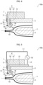
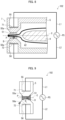
- Fig. 4 is a cross section showing a main part of a monitoring device 100a, which is a variation of the monitoring device 100 illustrated in Fig. 2 .
- a tip part side of a cover 5 is not bent toward a center axis C, and an opening 51 having the same diameter as an inner diameter of the cover 5 is formed in a tip part of the cover 5.
- An attachment 6 consists of a single member in which a tubular part 61 and a tip wall 62 are integrally formed.
- An opening 63 of the attachment 6 is formed to have a smaller diameter than the opening 51 of the cover 5.
- On a back surface 6a of the attachment 6, a annular protrusion 66 protruding toward a lens 4 side (base end part side) is formed at a peripheral part surrounding the opening 63.
- a second electrode 72 is disposed on a part of the back surface 6b excluding the annular protrusion 66. Further, insulation putty 8 having fire resistance is disposed so as to cover a part of the second electrode 72 which part is located on a side of the annular protrusion 66.
- the monitoring device 100a includes the annular protrusion 66 and the insulation putty 8 and prevents a short circuit between a first electrode 71 and a second electrode 72 with use of the annular protrusion 66 and the insulation putty 8. This makes it possible to suitably prevent a short circuit between the first electrode 71 and the second electrode 72 without increasing the size of the device configuration of the monitoring device 100a.
- Fig. 5 is a cross section showing a main part of a monitoring device 100b, which is a variation of the monitoring device 100a illustrated in Fig. 4 .
- a second electrode 72 is disposed throughout a gap between a cover 5 and an attachment 6, and a part of the second electrode 72 is exposed on an outer circumferential surface of the cover 5.
- the second electrode 72 and an AC power supply PS are directly connected to each other by a second wire L2 without involvement of the cover 5, so that the second electrode 72 and the AC power supply PS are electrically connected to each other.
- the cover 5 does not need to be electrically conductive, and the cover 5 can be formed of a material that is not electrically conductive.
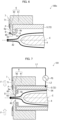
- Fig. 6 is a cross section showing a main part of a monitoring device 100c, which is a variation of the monitoring device 100 illustrated in Fig. 2 .
- a cover 5 has a tip part side thereof bent at an angle of substantially 90 degrees toward a center axis C side. As such, when an attachment 6 is attached to a tip part of the cover 5, substantially no gap is formed between the cover 5 and the attachment 6.
- the cover 5, which is electrically conductive, functions as a second electrode 72. This eliminates the need to provide a second electrode 72 to the attachment 6, so that the number of components of the monitoring device 100 can be reduced, and the device configuration can be simplified.
- a plasma P is more likely to be generated as the gas density is smaller.
- the inside of the cover 5 has a relatively high gas density compared to the outside (inside of the furnace 11) and thus tends to be an environment in which the plasma P is not easily generated.
- Fig. 7 is a cross section showing a main part of a monitoring device 101 in accordance with Embodiment 2.
- the monitoring device 101 differs from the above-described monitoring devices primarily in that a cover 5 is ceramic-coated.
- the cover 5 which is electrically conductive functions as a second electrode 72.
- a ceramic layer 54 is formed on a surface of the cover 5. The coating of the cover 5 with the ceramic layer 54 prevents a short circuit between a first electrode 71 and the cover 5 caused by a dielectric barrier discharge.
- the ceramic layer 54 may be formed only at a tip part of the cover 5 and in the vicinity thereof. In a case where a dielectric barrier discharge is generated, a creepage discharge occurs along a front surface 6a of an attachment 6. As such, even in a case where the ceramic layer 54 is formed only at the tip part of the cover 5 and in the vicinity thereof, a short circuit between the first electrode 71 and the cover 5 caused by a dielectric barrier discharge can be prevented.
- the ceramic layer 54 is formed on the cover 5.
- the cover 5 which is electrically conductive is caused to function as the second electrode 72 of the plasma actuator 7, a short circuit caused by a dielectric barrier discharge is prevented. This makes it possible to increase the safety of the monitoring device 101.
- Fig. 8 is a cross section showing a main part of a monitoring device 102 in accordance with Embodiment 3.
- Fig. 9 is an enlarged view schematically illustrating the vicinity of an opening 51 of the monitoring device 102 illustrated in Fig. 8 .
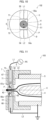
- Fig. 10 is a schematic view of the monitoring device 102 illustrated in Fig. 8 , which schematic view is obtained when the monitoring device 102 is viewed from a tip part side.
- the monitoring device 102 differs from the above-described monitoring devices primarily in that an attachment 6 is formed integrally with a cover 5.
- the attachment 6 is formed integrally with the cover 5, and a plasma actuator 7 is mounted on the cover 5.
- the cover 5 is made of a dielectric with a high insulation property (a material having an insulation property) such as sapphire glass.
- a first accommodation recess 55 and a second accommodation recess 56 are formed from an outer circumferential surface of the cover 5 toward an opening 51, at respective positions where the first accommodation recess 55 and the second accommodation recess 56 face each other with an opening 51 interposed therebetween.
- Respective bottom parts (deep parts) 55a and 56a of the first accommodation recess 55 and the second accommodation recess 56 face each other with the opening 51 interposed therebetween.
- the plasma actuator 7 includes a first electrode 71 and a second electrode 72, each of which has a plate-like shape.
- the first electrode 71 is accommodated in the bottom part 55a of the first accommodation recess 55.
- the second electrode 72 is accommodated in the bottom part 56a of the second accommodation recess 56.
- the first electrode 71 and the second electrode 72 face each other with the opening 63 (center axis C) interposed therebetween.
- the plasma actuator 7 has the first electrode 71 and the second electrode 72 disposed with the cover 5 made of a dielectric interposed therebetween. As such, when a high-frequency voltage is applied by an AC power supply PS, a dielectric barrier discharge is generated between the first electrode 71 and the second electrode 72, so that a plasma P is generated. This makes it possible to remove dust adhering to the opening 51 of the cover 5.
- the cover 5 can be made of a material other than sapphire glass.
- the cover 5 can also be made of, for example, quartz glass or a machinable ceramic. This makes it possible to reduce the manufacturing cost of the cover 5.
- the length D h of the opening 51 (the first electrode 71 and the second electrode 72) of the cover 5 in the center axis C direction is too great, an image captured by the camera 3 may be affected.
- the length D h is appropriately set to a size that does not affect the captured image.
- the space D s is appropriately set on the basis of dimensions of the opening 51, a voltage to be applied, and the like.
- the first electrode 71 and the second electrode 72 are disposed with the opening 51 (center axis C) of the cover 5 interposed therebetween.
- dust D adhering to the opening 51 of the cover 5 can be removed by a dielectric barrier discharge.
- the attachment 6 can be omitted in the monitoring device 102, the number of components of the monitoring device 102 can be reduced, and the device configuration can be simplified.
- Fig. 11 is a cross section showing a main part of a monitoring device 103 in accordance with Embodiment 4.
- Fig. 12 is a schematic view of the monitoring device 103 illustrated in Fig. 11 , which schematic view is obtained when the monitoring device 103 is viewed from a tip part side.
- the monitoring device 103 differs from the above-described monitoring devices primarily in that a first electrode 71 and a second electrode 72 are embedded in an attachment 6.
- a cover 5 is made of a metal
- the attachment 6 is made of a machinable ceramic.
- circular first accommodation recess 67 and a circular second accommodation recess 68 are formed from an outer circumferential surface of the attachment 6 toward an opening 63, at respective positions where the first accommodation recess 67 and the second accommodation recess 68 face each other with an opening 63 interposed therebetween.
- Respective bottom parts (deep parts) 67a and 68a of the first accommodation recess 67 and the second accommodation recess 68 face each other with the opening 63 interposed therebetween.
- a plasma actuator 7 includes a first electrode 71 and a second electrode 72, each of which has a pillar shape.
- the first electrode 71 is inserted into a bottomed cylindrical sapphire glass tube 73, which is made of sapphire glass.
- the first electrode 71 is accommodated in the first accommodation recess 67 while being inserted into the sapphire glass tube 73.
- the second electrode 72 is accommodated in the second accommodation recess 68.
- the first electrode 71 and the second electrode 72 face each other with the opening 63 (center axis C) interposed therebetween.
- the plasma actuator 7 has the first electrode 71 and the second electrode 72 disposed such that the sapphire glass tube 73 and the attachment 6 made of the machinable ceramic are interposed between the first electrode 71 and the second electrode 72.
- a dielectric barrier discharge is generated between the first electrode 71 and the second electrode 72, so that a plasma P is generated. This makes it possible to remove dust D adhering to the opening 63 of the attachment 6.
- the sapphire glass tube 73 may be attached not only to the first electrode 71 but also to the second electrode 72. However, not attaching the sapphire glass tube 73 to the second electrode 72 reduces a space D s between the first electrode 71 and the second electrode 72 is reduced. This makes it possible to reduce a voltage for generating a dielectric barrier discharge.
- the plasma actuator 7 includes the first electrode 71 and the second electrode 72, each of which has a pillar shape, and the first electrode 71 and the second electrode 72 are disposed with the opening 63 (center axis C) of the attachment 6 interposed therebetween.
- dust D adhering to the opening 63 of the attachment 6 can be removed by a dielectric barrier discharge.
- Fig. 13 is a cross section showing a main part of a monitoring device 104 in accordance with Embodiment 5.
- Fig. 14 is a schematic view of the monitoring device 104 illustrated in Fig. 13 , which schematic view is obtained when the monitoring device 104 is viewed from a tip part side.
- the monitoring device 104 differs from the above-described monitoring devices primarily in that a first electrode 71 is made of a string-shaped metal wire.
- a plasma actuator 7 includes two first electrodes 71 each made of a string-shaped metal wire. Each of the first electrodes 71 is inserted into a cylindrical sapphire glass tube 73, which is made of sapphire glass. One end of the sapphire glass tube 73 is closed by insulation putty 8. Instead of the sapphire glass tube 73, an insulation tube made of, for example, a material having an insulating property such as ceramics may be used.
- the first electrodes 71 are disposed on a surface 5a of the cover 5 on a tip part side of the cover 5 so as to be parallel to each other with an opening 51 (center axis C) interposed therebetween.
- a dielectric barrier discharge is generated along the surface 5a of the cover 5, so that a plasma P is generated in the vicinity of a side surface of each of the string-shaped first electrodes 71.
- ambient air is induced by the plasma P, so that an induced jet flow F toward the center axis C and an induced jet flow F toward a side opposite to the center axis C are generated. This makes it possible to remove dust D adhering to the opening 51 of the cover 5.
- the plasma actuator 7 includes the two first electrodes 71, each of which is in the form of a line, and the two first electrodes 71 are disposed with the opening 51 (center axis C) of the cover 5 interposed therebetween.
- dust D adhering to the opening 51 of the cover 5 can be removed by a dielectric barrier discharge.
- Fig. 15 is a cross section showing a main part of a monitoring device 104a, which is a variation of the monitoring device 104 illustrated in Fig. 13 .
- insulation putty 8 is further provided such that a sapphire glass tube 73 is interposed between the first electrodes 71.
- the provision of the insulation putty 8 inhibits generation of a dielectric barrier discharge toward a side opposite to the opening 51 of the cover 5 (center axis C). It is therefore possible to generate a dielectric barrier discharge toward the opening 51 (center axis C).
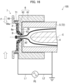
- Fig. 16 is a cross section showing a main part of a monitoring device 105 in accordance with Embodiment 6.
- the monitoring device 105 differs from the above-described monitoring devices primarily in that a first electrode 71 is made of a coiled metal wire.
- an attachment 6 in the monitoring device 102, includes an annular accommodation recess 69 that is formed so as to protrude from a front surface 6a of the attachment 6 toward an inside 11 of the furnace.
- the accommodation recess 69 is open in a direction opposite to an opening 63 (center axis C) and is provided annularly so as to surround the opening 63.
- the attachment 6 is made of a dielectric such as a machinable ceramic, sapphire glass, or the like.
- a plasma actuator 7 includes the first electrode 71 made of a coiled metal wire.
- the coiled first electrode 71 is disposed in the accommodation recess 69 of the attachment 6 while being wound around a bottom part (deep part) 69a of the accommodation recess 69. That is, the coiled first electrode 71 is disposed so as to surround an opening 51 (center axis C) of the cover 5.
- a high-frequency voltage is applied by an AC power supply PS
- a dielectric barrier discharge is generated along the front surface 6a of the attachment 6, so that a plasma P is generated in the vicinity of an inner diameter side of the coiled first electrode 71.
- ambient air is induced by the plasma P, so that an induced jet flow F toward the center axis C is generated. This makes it possible to remove dust D adhering to the opening 63 of the attachment 6.
- the plasma actuator 7 includes the coiled first electrode 71, and the coiled first electrode 71 is disposed so as to surround the opening 51 of the cover 5. As such, with the monitoring device 105, dust D adhering to the opening 63 of the attachment 6 can be removed by a dielectric barrier discharge.
- Fig. 17 is a cross section showing a main part of a monitoring device 105a, which is a variation of the monitoring device 105 illustrated in Fig. 16 .
- an accommodation recess 69 of an attachment 6 is made of a material different from those of the other portions (a tubular part 61 and a tip wall 62) of the attachment 6.
- the attachment 6 has a hybrid structure in which the accommodation recess 69 is made of sapphire glass and portions of the attachment 6 other than the accommodation recess 69 are made of a machinable ceramic. In a case where the portions other than the accommodation recess 69 are made of a machinable ceramic, the manufacturing cost of the attachment 6 can be reduced.
- Fig. 18 is a cross section showing a main part of a monitoring device 106 in accordance with Embodiment 7.
- the monitoring device 106 differs from the above-described monitoring devices primarily in that an opening 63 of an attachment 6 is closed by a dielectric 9.
- a plasma actuator 7 includes the dielectric 9.
- a center part of the dielectric 9 is transparent in order to secure the field of view of a lens 4.
- two first electrodes 71 and two second electrodes 72 are disposed alternately in a direction of a center axis C.
- the two sets, each consisting of a first electrode 71 and a second electrode 72, are disposed, for example, on a tip part side and a base end part side of the dielectric 9, respectively, so as to surround a periphery of the dielectric 9.
- the dielectric 9 is disposed so as to close the opening 63 of the attachment 6.
- an exhaust port 60 is formed in a circumferential wall of the attachment 6, so that second sealing air A2 is discharged from the exhaust port 60.
- the monitoring device 106 includes a blower B for blowing air along a tip part side of the opening 63 of the attachment 6.
- the blower B scatters dust D that cannot be removed by an induced jet flow F caused by a dielectric barrier discharge of the plasma actuator 7.
- the plasma actuator 7 is configured such that each first electrode 71 and each second electrode 72 are disposed with the dielectric 9 interposed therebetween. As such, when a high-frequency voltage is applied by an AC power supply PS, a dielectric barrier discharge is generated, so that a plasma P is generated between each first electrode 71 and each second electrode 72.
- the dielectric 9 is disposed so as to close the opening 63 of the attachment 6. As such, with the monitoring device 106, dust D generated in the inside 11 of the furnace is less likely to infiltrate an inside of the monitoring device 106. This makes it possible to prevent the dust D from adhering to the lens 4 and the cover 5.
- Fig. 19 is a cross section showing a main part of a monitoring device 107 in accordance with Embodiment 8.
- the monitoring device 107 differs from the above-described monitoring devices primarily in that a first electrode 71 and a second electrode 72 are disposed at a circumferential wall of a cover 5.
- a plasma actuator 7 includes the first electrode 71 and the second electrode 72, each of which has a pillar shape.
- the first electrode 71 is inserted into a bottomed cylindrical sapphire glass tube 73, which is made of sapphire glass.
- the first electrode 71 is penetrated into the circumferential wall 57 of the cover 5 in a thickness direction while being inserted into the sapphire glass tube 73.
- the second electrode 72 is penetrated into the circumferential wall 57 of the cover 5 in the thickness direction.
- the first electrode 71 and the second electrode 72 are disposed at positions where the first electrode 71 and the second electrode 72 face each other with the lens 4 interposed therebetween.
- the shapes of the first electrode 71 and the second electrode 72 are not limited to a columnar shape.
- the first electrode 71 and the second electrode 72 can each, for example, have a shape other than a pillar shape, such as a plate-like shape.
- the cover 5 which is electrically conductive can be caused to function as the second electrode 72.
- the first electrode 71 and the second electrode 72 are disposed at the circumferential wall 57 of the cover 5 covering an outer circumferential surface of the lens 4, so as to face each other with the lens 4 interposed therebetween.
- a dielectric barrier discharge can be generated inside the cover 5, and dust D that has intruded into the inside of the cover 5 and is adhering to the lens 4 can be removed by the dielectric barrier discharge.
- Fig. 20 is a cross section showing a main part of a monitoring device 108 in accordance with Embodiment 9.
- Fig. 21 is a schematic view of the monitoring device 108 illustrated in Fig. 20 , which schematic view is obtained when the monitoring device 108 is viewed from a tip part side.
- the monitoring device 108 differs from the above-described monitoring devices primarily in including a dielectric plate 10 made of a dielectric (insulator).
- a plasma actuator 7 includes the dielectric plate 10 having an annular shape.
- the dielectric plate 10 is made of a dielectric (insulator) such as machinable ceramics, sapphire glass, or the like.
- the dielectric plate 10 has an annular shape (ring shape) having a center on a center axis C, and is installed in an opening 51 of a cover 5.
- a first electrode 71 and a second electrode 72 each have an annular shape (ring shape) and are each disposed so as to have a center on the center axis C.
- the first electrode 71 is formed to have a diameter larger than that of the second electrode 72, and an inner diameter of the first electrode 71 is substantially equal to an outer shape of the second electrode 72.
- the first electrode 71 and the second electrode 72 are disposed with the dielectric plate 10 interposed therebetween.
- the first electrode 71 is disposed on a front surface 10a of the dielectric plate 10, which front surface 10a is on a tip part side of the dielectric plate 10, and the second electrode 72 is disposed on a back surface 10b of the dielectric plate 10, which back surface 10b is on a base end part side (side opposite to the surface 10a) of the dielectric plate 10.
- the plasma actuator 7 has the annular first electrode 71 and the annular second electrode 72 disposed in the manner described above such that the dielectric plate 10 is interposed between the first electrode 71 and the second electrode 72.
- a dielectric barrier discharge is generated along the front surface 10a of the dielectric plate 10, so that a plasma P is generated in the vicinity of an inner diameter side edge of the annular first electrode 71.
- ambient air is induced by the plasma P, so that an induced jet flow F toward the center axis C is generated.
- the plasma actuator 7 makes it possible to remove dust D that cannot be dealt with conventionally and thus to improve narrowing of the field of view of the monitoring device 100 caused by adherence of the dust D.
- the first electrode 71 and the second electrode 72 are disposed on the dielectric plate 10, which is disposed in the opening 51 of the cover 5, such that the dielectric plate 10 is interposed between the first electrode 71 and the second electrode 72.
- the monitoring device 108 it is possible to generate a dielectric barrier discharge at the opening 51 of the cover 5 where adherence of dust D is particularly likely to occur, and to thereby remove the dust D.
- Fig. 22 is a cross section showing a main part of a monitoring device 109 in accordance with Embodiment 10.
- the monitoring device 109 differs from the above-described monitoring devices primarily in that a first wire L1 and a second wire L2 are disposed on an inner circumferential surface of an attachment 6 or inside a circumferential wall of the attachment 6.
- the first wire L1 which electrically connects a first electrode 71 and an AC power supply PS to each other, is spirally disposed on the inner circumferential surface of the attachment 6 made of an insulator.
- the second wire L2 which electrically connects a second electrode 72 and the AC power supply PS to each other, is disposed spirally on the inner circumferential surface of the attachment 6, which has a tubular shape.
- the first wire L1 and the second wire L2 are disposed in a double spiral shape on the inner circumferential surface of the attachment 6.
- the first wire L1 and the second wire L2 are thus disposed on the inner circumferential surface of the attachment 6, thereby eliminating the processing for forming a through hole 64 (see Fig. 2 ) for wiring in the attachment 6, for example. Further, it becomes unnecessary to wire the first wire L1 and the second wire L2 through an outside of the attachment 6, and the first wire L1 and the second wire L2 are therefore not exposed to an outside of the monitoring device 109.
- the first wire L1 and the second wire L2 are disposed on the inner circumferential surface of the attachment 6 or inside the circumferential wall of the attachment 6. As such, with the monitoring device 109, processing of the attachment 6 can be facilitated, and safety of the monitoring device 109 can be improved.
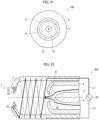
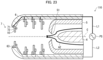
- Fig. 23 is a cross section showing a main part of a monitoring device 110 in accordance with Embodiment 11.
- the monitoring device 110 differs from the above-described monitoring devices primarily in that a plurality of plasma actuators 7 are disposed so as to be spaced apart from each other.
- the monitoring device 110 includes a plurality of (four in the example of Fig. 23 ) plasma actuators 7 each including a first electrode 71, a second electrode 72, and a dielectric plate 10.
- the plurality of plasma actuators 7 are disposed on an attachment 6 so as to have a center on a center axis C.
- One of the plurality of plasma actuators 7 is disposed in an opening 63 of the attachment 6 or on an inner circumferential surface of the attachment 6 in the vicinity of the opening 63.
- three plasma actuators 7 are disposed on the inner circumferential surface of the attachment 6 at intervals in a direction of the center axis C.
- each of the plasma actuators 7 are electrically connected to an AC power supply PS via a first wire L1 and a second wire L2 which are disposed on the inner circumferential surface of the attachment 6 or inside the circumferential wall of the attachment 6.
- the three plasma actuators 7 provided on the inner circumferential surface of the attachment 6 gradually increase in width of the dielectric plate 10 (width of the cover 5 in a radial direction) from a tip part side toward a base end part side such that the dielectric plate 10 located at the tip part side has the smallest width, and the dielectric plate 10 located at the base end part side has the largest width.
- the monitoring device 110 in accordance with Embodiment 11 includes the plurality of plasma actuators 7.
- the monitoring device 110 allows for more dielectric barrier discharges to be generated.
- each plasma actuator 7 by controlling each plasma actuator 7 so as to maximize an induced jet flow F, it is possible to adjust a timing of generation of an electric barrier discharge.
- the present invention is not limited to the embodiments, but can be altered by a skilled person in the art within the scope of the claims.
- the present invention also encompasses, in its technical scope, any embodiment derived by combining technical means disclosed in differing embodiments.
Landscapes
- Engineering & Computer Science (AREA)
- General Engineering & Computer Science (AREA)
- Plasma & Fusion (AREA)
- Physics & Mathematics (AREA)
- Chemical & Material Sciences (AREA)
- Combustion & Propulsion (AREA)
- Mechanical Engineering (AREA)
- Spectroscopy & Molecular Physics (AREA)
- Plasma Technology (AREA)
- Closed-Circuit Television Systems (AREA)
- Studio Devices (AREA)
- Camera Bodies And Camera Details Or Accessories (AREA)
- Eyeglasses (AREA)
- Blocking Light For Cameras (AREA)
- Cleaning In General (AREA)
Abstract
Description
- The present invention relates to a monitoring device, more specifically a monitoring device for monitoring an inside of a furnace.
- Conventionally, a combustion furnace in a waste-to-energy plant or the like is provided with a monitoring device for monitoring a state of an inside of the furnace. This type of monitoring device suffers adherence of dust (contaminant) to a lens and the like as a result of combustion. A technique for preventing adherence of dust or removal of dust has therefore been proposed.
- For example,
Patent Literature 1 discloses a technique of releasing a dust prevention gas toward a tip part side of a lens tube.Patent Literature 2 discloses a technique of attaching, to a tip part side of a lens tube, a rotatable transparent body with blades (propeller mechanism). -
- [Patent Literature 1]
Japanese Utility Model Application Publication, Jitsukaihei, No. 5-647000 - [Patent Literature 2]
Japanese Patent Application Publication, Tokukaihei, No. 2004-96675 - However, the technique of
Patent Literature 1 cannot sufficiently prevent adherence of dust and requires periodical removal (blowing off) of dust by hand. Furthermore, there may be dust that cannot be removed even by hand (for example, dust that has entered an inner circumferential part of an opening) and causes a partial loss of the field of view of a captured image. - Further, the technique of
Patent Literature 2 has problems caused by the addition of the propeller mechanism, such as that maintenance of the propeller mechanism is required and that the propeller mechanism undesirably appears in an image captured by a camera. These problems make it difficult to apply the technique ofPatent Literature 2. - It is an object of an aspect of the present invention to provide a monitoring device in which narrowing of a field of view due to adherence of dust can be improved without frequent maintenance.
- In order to attain the object, a monitoring device in accordance with an aspect of the present invention is a monitoring device for monitoring an inside of a furnace, including: a light guide part guiding light from the inside of the furnace to a camera; a cover having a tubular shape, covering a circumferential surface of the light guide part, and having, in a tip part of the cover on a side of the inside of the furnace, an opening that lets light pass therethrough; and a plasma actuator including a first electrode that generates, toward a center axis of the cover, at least one of (i) a plasma generated by a dielectric barrier discharge and (ii) a jet flow induced due to the plasma, the plasma actuator removing, with use of at least one of the plasma and the jet flow, dust adhering to a surface of the monitoring device which surface faces the inside of the furnace or to an inside of the monitoring device.
- An aspect of the present invention makes it possible to provide a monitoring device in which narrowing of a field of view due to adherence of dust can be improved without frequent maintenance.
-
-
Fig. 1 is a cross-sectional view illustrating a state in which a monitoring device in accordance withEmbodiment 1 is attached to a furnace. -
Fig. 2 is a cross section showing a main part of the monitoring device illustrated inFig. 1 . -
Fig. 3 is a front view of the monitoring device illustrated inFig. 1 , which front view is obtained when the monitoring device is viewed from a tip part side. -
Fig. 4 is a cross section showing a main part of a variation of the monitoring device illustrated inFig. 2 . -
Fig. 5 is a cross section showing a main part of a variation of the monitoring device illustrated inFig. 4 . -
Fig. 6 is a cross section showing a main part of a variation of the monitoring device illustrated inFig. 2 . -
Fig. 7 is a cross section showing a main part of a monitoring device in accordance withEmbodiment 2. -
Fig. 8 is a cross section showing a main part of a monitoring device in accordance withEmbodiment 3. -
Fig. 9 is an enlarged view schematically illustrating the vicinity of an opening of the monitoring device illustrated inFig. 8 . -
Fig. 10 is a schematic view of the monitoring device illustrated inFig. 8 , which schematic view is obtained when the monitoring device is viewed from a tip part side. -
Fig. 11 is a cross section showing a main part of a monitoring device in accordance withEmbodiment 4. -
Fig. 12 is a schematic view of the monitoring device illustrated inFig. 11 , which schematic view is obtained when the monitoring device is viewed from a tip part side. -
Fig. 13 is a cross section showing a main part of a monitoring device in accordance withEmbodiment 5. -
Fig. 14 is a schematic view of the monitoring device illustrated inFig. 13 , which schematic view is obtained when the monitoring device is viewed from a tip part side. -
Fig. 15 is a cross section showing a main part of a variation of the monitoring device illustrated inFig. 13 . -
Fig. 16 is a cross section showing a main part of a monitoring device in accordance withembodiment 6. -
Fig. 17 is a cross section showing a main part of a variation of the monitoring device illustrated inFig. 16 . -
Fig. 18 is a cross section showing a main part of a monitoring device in accordance withEmbodiment 7. -
Fig. 19 is a cross section showing a main part of a monitoring device in accordance withEmbodiment 8. -
Fig. 20 is a cross section showing a main part of a monitoring device in accordance withEmbodiment 9. -
Fig. 21 is a schematic view of the monitoring device illustrated inFig. 20 , which schematic view is obtained when the monitoring device is viewed from a tip part side. -
Fig. 22 is a cross section showing a main part of a monitoring device in accordance withEmbodiment 10. -
Fig. 23 is a cross section showing a main part of a monitoring device in accordance withEmbodiment 11. - The following will describe an embodiment of the present invention, with reference to
Figs. 1 to 6 . Note that the following description is an example of a monitoring device in accordance with the present invention, and the technical scope of the present invention is not limited to the examples illustrated in the drawings. - First, with reference to
Fig. 1 , an outline of amonitoring device 100 in accordance withEmbodiment 1 will be described.Fig. 1 is a cross-sectional view illustrating a state in which themonitoring device 100 in accordance withEmbodiment 1 is attached to afurnace 1. In the following description, a side (left side inFig. 1 ) facing aninside 11 of thefurnace 1 may be referred to as a tip part side, and a side (right side inFig. 1 ) opposite to the tip part side may be referred to as a base end part side. - The
furnace 1 illustrated inFig. 1 is, for example, a combustion furnace or a melting furnace, and theinside 11 of the furnace is exposed to a high-temperature atmosphere. Themonitoring device 100 is attached to afurnace wall 12, which is a side wall, an upper wall, or the like of thefurnace 1, in order to monitor the state of theinside 11 of the furnace. In the illustrated example, atubular mounting tool 2 is provided in amounting hole 13 formed in a thickness direction of thefurnace wall 12, and a tip part side of themonitoring device 100 is inserted into themounting hole 13 via themounting tool 2. - The
mounting tool 2 has formed therein afirst vent 21 for introducing first sealing air A1 for dust prevention into an inside of themounting tool 2 is formed in themounting tool 2. The first sealing air A1 introduced from thefirst vent 21 flows, from the base end part side toward the tip part side, through a gap between an outer circumferential surface of acover 5 of themonitoring device 100 and an inner circumferential surface of themounting tool 2 and is discharged from a tip part side of themounting tool 2. The introduction of the first sealing air A1 into the inside of themounting tool 2 prevents dust generated in theinside 11 of the furnace from adhering to a surface of themonitoring device 100 which surface faces theinside 11 of the furnace. The introduction also cools thecover 5 and thus prevents an excessive increase in temperature of the lens (light guide part) 4. - The
monitoring device 100 includes acamera 3, thelens 4 which guides light from theinside 11 of the furnace to thecamera 3, thetubular cover 5 which covers an outer circumferential surface (circumferential surface) of thelens 4, and anattachment 6 on which a plasma actuator to be described later is mounted. Thecamera 3 is connected to a base end part side of thelens 4 and captures an image of a state of theinside 11 of the furnace on the basis of the light guided by thelens 4. As thecamera 3, for example, a CCD camera or the like is used. Thelens 4 and thecover 5 are disposed such that respective center axes C coincide with each other. Anopening 51 which lets light pass therethrough is formed at a tip part of thecover 5. Theattachment 6 is detachably attached to the tip part of thecover 5 so as to surround a periphery of theopening 51 of thecover 5. - The
monitoring device 100 has formed therein asecond vent 52 for introducing second sealing air A2 for dust prevention into an inside of thecover 5. The second sealing air A2 introduced from thesecond vent 52 flows through a gap between the outer circumferential surface of thelens 4 and an inner circumferential surface of thecover 5 from the base end part side toward the tip part side, and is discharged from theopening 51 formed in the tip part of thecover 5. The second sealing air A2 prevents dust generated in the inside 11 of the furnace from adhering to the surface of themonitoring device 100 which surface faces the inside 11 of the furnace, and also prevents an excessive increase in temperature of thelens 4 by cooling thelens 4. - The
monitoring device 100 uses the first sealing air A1 and the second sealing air A2 to prevent dust generated in the inside 11 of the furnace from adhering to themonitoring device 100. However, adherence of dust cannot be completely prevented, and dust may adhere to the surface of themonitoring device 100 which surface faces the inside 11 of the furnace. In a case where dust adheres to themonitoring device 100, a part of the field of view of an image captured by thecamera 3 may be lost. This makes it difficult to properly monitor the state of the inside 11 of the furnace. - As such, the
monitoring device 100 includes the plasma actuator and removes dust adhering to themonitoring device 100 with use of a dielectric barrier discharge (DBD) by the plasma actuator to improve narrowing of the field of view caused by adherence of dust. - In the example illustrated in
Fig. 1 , themonitoring device 100 is attached to thefurnace wall 12 at an angle at which the center axis C vertically intersects with thefurnace wall 12 of thefurnace 1. Note that themonitoring device 100 can be attached to thefurnace wall 12 at an angle at which the center axis C obliquely intersects with thefurnace wall 12. - Next, with reference to
Figs. 2 and 3 , the following will specifically describe a main part of themonitoring device 100 in accordance withEmbodiment 1.Fig. 2 is a cross section showing a main part of themonitoring device 100 illustrated inFig. 1 .Fig. 3 is a front view of themonitoring device 100 illustrated inFig. 1 , which front view is obtained when themonitoring device 100 is viewed from the tip part side. As illustrated inFigs. 2 and 3 , themonitoring device 100 is configured such that theattachment 6 is mounted on the tip part side of thecover 5 covering the outer circumferential surface of thelens 4. Afirst electrode 71 and asecond electrode 72 of aplasma actuator 7 are disposed on theattachment 6. - The
lens 4 is a substantially cylindrical lens tube. Thelens 4 has a function of adjusting a focal position of light so that a clear image can be captured by thecamera 3. Thelens 4 may be, for example, constituted by a plurality of lenses combined together. - The
cover 5 is an electrically conductive tubular member. Thecover 5 is made of, for example, a metal tube such as SUS. Thecover 5 is disposed so as to cover a substantially entire length of thelens 4 from a tip part side of thelens 4 to a base end part side of thelens 4. The tip part of thecover 5 curvilinearly bends toward the center axis C. Acircular opening 51 having a center on the center axis C is formed in the tip part. Theopening 51 is formed to have a smaller diameter than an inner diameter of thecover 5. In a case where an opening area of theopening 51 is thus relatively reduced, dust D generated in the inside 11 of the furnace is less likely to infiltrate the inside of thecover 5 through theopening 51. At a peripheral part surrounding theopening 51, aninclined surface 53 which is inclined toward the base end part side with respect to the center axis C is formed. - The
attachment 6 is a mounting tool for attaching theplasma actuator 7 to thecover 5. InEmbodiment 1, theattachment 6 is made of a dielectric (insulator). Examples of the dielectric (insulator) include machinable ceramics, high temperature co-fired ceramics (HTCC), low temperature co-fired ceramics (LTCC), a stacked package thereof, and sapphire glass. Theattachment 6 is constituted by the following two members: a cylindricaltubular part 61 which fits on the outer circumferential surface of thecover 5; and a disk-shapedtip wall 62 which is provided on a tip part side of thetubular part 61. Thetip wall 62 has formed therein acircular opening 63 having a center on the center axis C. Theopening 63 of theattachment 6 is formed to have a diameter larger than that of theopening 51 of thecover 5 so that theinclined surface 53 of thecover 5 is exposed at a tip part of themonitoring device 100. Light from the inside 11 of the furnace passes through theopening 63 of theattachment 6 and theopening 51 of thecover 5 and enters thelens 4. - The
plasma actuator 7 is a device that generates a plasma P and an induced jet flow (jet flow) F by a dielectric barrier discharge. Theplasma actuator 7 includes thefirst electrode 71 and thesecond electrode 72. Each of thefirst electrode 71 and thesecond electrode 72 has an annular shape (ring shape) and is disposed to have a center on the center axis C. Thefirst electrode 71 is formed to have a diameter larger than that of thesecond electrode 72, and an inner diameter of thefirst electrode 71 is substantially equal to an outer diameter of thesecond electrode 72. - The
first electrode 71 and thesecond electrode 72 can each have one or more gaps formed in part thereof. In a case where, for example, a plurality of gaps separate each electrode into segments, maintaining the segments to be at the same electric potential allows forming electrodes that are disposed in an annular shape as a whole. Segmenting each electrode in this way provides, for example, the following remarkable effect. That is, by disposing each electrode such that the respective positions of the gaps are displaced from each other at a constant angle in a circumferential direction of the center axis C, it is possible to generate an induced jet flow F swirling around the center axis C. Note that thefirst electrode 71 and thesecond electrode 72 are each not limited to a circular annular shape. Thefirst electrode 71 and thesecond electrode 72 may each have an annular shape other than a circular shape, such as a polygonal shape, for example. - The
first electrode 71 and thesecond electrode 72 are disposed with thetip wall 62 of theattachment 6 interposed therebetween. Thefirst electrode 71 is disposed on afront surface 6a of thetip wall 62 of theattachment 6, whichfront surface 6a is on the tip part side of thetip wall 62. Thefirst electrode 71 may be disposed such that all or part of thefirst electrode 71 is embedded in theattachment 6. Thesecond electrode 72 is disposed on aback surface 6b of thetip wall 62 of theattachment 6, which backsurface 6b is on a base end part side (side opposite to thefront surface 6a) of thetip wall 62. More specifically, in a gap formed between thecover 5 and theattachment 6, thesecond electrode 72 is disposed on theback surface 6b while being in contact with the tip part of thecover 5. - The
first electrode 71 and thesecond electrode 72 are electrically connected to an AC power supply PS. The AC power supply PS is a power supply capable of outputting a high voltage having, for example, a sine waveform or a pulse waveform at a high frequency. In the illustrated example, thefirst electrode 71 is electrically connected to the AC power supply PS via a first wire L1. The first wire L1 has one end connected to the AC power supply PS and the other end connected to thefirst electrode 71 through a throughhole 64 for wiring formed in theattachment 6. Thesecond electrode 72 is electrically connected to the AC power supply PS via the electricallyconductive cover 5 and a second wire L2. The second wire L2 has one end connected to the AC power supply PS and the other end connected to the electricallyconductive cover 5. - It is not essential that the
attachment 6 has formed therein the throughhole 64 through which the first wire L1 is passed. In this case, the other end of the first wire L1 may be connected to thefirst electrode 71 through an outside of theattachment 6 so that thefirst electrode 71 and the AC power supply PS are electrically connected to each other. - The
plasma actuator 7 has the annularfirst electrode 71 and the annularsecond electrode 72 disposed in the manner described above such that thetip wall 62 of theattachment 6 made of a dielectric is interposed between thefirst electrode 71 and thesecond electrode 72. As such, when a high-frequency voltage is applied by the AC power supply PS, a dielectric barrier discharge is generated along thefront surface 6a of theattachment 6. This causes a plasma P to be generated in the vicinity of an inner diameter side edge of the annularfirst electrode 71. Further, charged particles resulting from the production of the plasma P are accelerated by an electric field, and ambient air is induced, so that an induced jet flow F toward the center axis C is generated. - The
plasma actuator 7 removes dust D adhering to themonitoring device 100, with use of at least one of a plasma P caused by a dielectric barrier discharge and an induced jet flow F. For example, theplasma actuator 7 breaks down dust D adhering to themonitoring device 100, with use of a plasma P caused by a dielectric barrier discharge. Theplasma actuator 7 also scatters dust D adhering to themonitoring device 100, with use of an induced jet flow F caused by a dielectric barrier discharge. Alternatively, theplasma actuator 7 breaks down and scatters dust D adhering to themonitoring device 100, with use of both a plasma P caused by a dielectric barrier discharge and an induced jet flow F. - Thus, the
plasma actuator 7 makes it possible to remove dust D that cannot be dealt with conventionally and thus to improve narrowing of the field of view of themonitoring device 100 caused by adherence of the dust D. - In the above description, an example has been described in which the
attachment 6 made of a dielectric is constituted by the following two members: thetubular part 61 and thetip wall 62. However, theattachment 6 may consist of a single member in which thetubular part 61 and thetip wall 62 are integrally formed. Further, in order for theplasma actuator 7 to generate a dielectric barrier discharge, it is sufficient that at least thetip wall 62 is made of a dielectric having a high insulation property. As such, thetubular part 61 may be made of a material other than a dielectric having a high insulation property. This makes it possible to reduce the manufacturing cost of theattachment 6. - Next, an example of control of the
monitoring device 100 will be described. Themonitoring device 100 may control theplasma actuator 7 to generate a dielectric barrier discharge continuously or intermittently. Themonitoring device 100 may also generate a dielectric barrier discharge in accordance with a state of dust D adherence, an amount of dust D generated, or the like. - For example, the
monitoring device 100 may process an image captured by thecamera 3 and, in a case where it is determined from the captured image that there is adherent dust D, generate a dielectric barrier discharge. - The
monitoring device 100 may also detect, with use of a sensor, an amount of waste introduced to thefurnace 1, a speed of a grate, an evaporation amount, and/or the like, and generate a dielectric barrier discharge by predicting an amount of fly ash generated in accordance with value(s) thus detected. - The
monitoring device 100 may adjust an intensity of an electric current of the dielectric barrier discharge, a frequency of the dielectric barrier discharge, and/or a direction of an air stream (induced jet flow F) in accordance with a degree of adherence of dust D and/or a position to which dust D is adhering. - Further, the
monitoring device 100 may include a plurality offirst electrodes 71 so as to maximize an induced jet flow F, and a timing of generating an electric barrier discharge may be adjusted. - As described above, the
monitoring device 100 in accordance withEmbodiment 1 includes: thelens 4 guiding light from the inside 11 of the furnace to thecamera 3; thecover 5 having a tubular shape, covering the outer circumferential surface of thelens 4, and having, in the tip part of thecover 5 on the side of the inside 11 of the furnace, theopening 51 that lets light pass therethrough; and theplasma actuator 7 including thefirst electrode 71 that generates, toward the center axis C of thecover 5, at least one of (i) a plasma P generated by a dielectric barrier discharge and (ii) an induced jet flow F induced due to the plasma P, theplasma actuator 7 removing, with use of at least one of the plasma P and the induced jet flow F, dust D adhering to the surface of themonitoring device 100 which surface faces the inside 11 of the furnace. - Since dust D adhering to the
monitoring device 100 is removed by a dielectric barrier discharge, themonitoring device 100 makes it possible to remove dust D that cannot conventionally be handled. As such, in accordance withEmbodiment 1, it is possible to provide themonitoring device 100 in which narrowing of the field of view due to adherence of dust D can be improved without frequent maintenance. - The
monitoring device 100 is preferably configured such that thefirst electrode 71 is disposed at theopening 51 of thecover 5 or at a side closer to the inside 11 of the furnace than theopening 51. This makes it possible to generate a dielectric barrier discharge at or in the vicinity of theopening 51 of thecover 5 where adherence of dust D is particularly likely to occur, and to thereby remove the dust D. - The
monitoring device 100 is preferably configured such that theplasma actuator 7 has the annularfirst electrode 71 disposed concentrically with theopening 51 of thecover 5. This makes it possible to generate a dielectric barrier discharge in the vicinity of theopening 51 of thecover 5 and remove the dust D. - The
monitoring device 100 is preferably configured such that theplasma actuator 7 is provided to theattachment 6. This facilitates attachment and detachment of theplasma actuator 7 to and from thecover 5, thereby improving maintainability of themonitoring device 100. - The
monitoring device 100 is preferably configured such that theattachment 6 is made of a dielectric. This allows theattachment 6 to function as a dielectric necessary for dielectric barrier discharge. As a result, the number of components of the monitoring device 100 (plasma actuator 7) can be reduced, and the device configuration can be simplified. -
Fig. 4 is a cross section showing a main part of amonitoring device 100a, which is a variation of themonitoring device 100 illustrated inFig. 2 . As illustrated inFig. 4 , in themonitoring device 100a, a tip part side of acover 5 is not bent toward a center axis C, and anopening 51 having the same diameter as an inner diameter of thecover 5 is formed in a tip part of thecover 5. - An
attachment 6 consists of a single member in which atubular part 61 and atip wall 62 are integrally formed. Anopening 63 of theattachment 6 is formed to have a smaller diameter than theopening 51 of thecover 5. On afront surface 6a of theattachment 6, aninclined surface 65 inclined toward a base end part side with respect to the center axis C is formed at a peripheral part surrounding theopening 63. On aback surface 6a of theattachment 6, aannular protrusion 66 protruding toward alens 4 side (base end part side) is formed at a peripheral part surrounding theopening 63. Asecond electrode 72 is disposed on a part of theback surface 6b excluding theannular protrusion 66. Further,insulation putty 8 having fire resistance is disposed so as to cover a part of thesecond electrode 72 which part is located on a side of theannular protrusion 66. - In a case where a dielectric barrier discharge is generated by the
plasma actuator 7, a creepage discharge occurs along thefront surface 6a of theattachment 6. As such, in a case where a creepage distance between thefirst electrode 71 and thesecond electrode 72 is small, there is a possibility that thefirst electrode 71 and thesecond electrode 72 are short-circuited. Thus, in order to prevent the short circuit, it is preferable to secure as great a creepage distance as possible between thefirst electrode 71 and thesecond electrode 72. There can be a case, however, that due to issues such as space, the creepage distance between thefirst electrode 71 and thesecond electrode 72 cannot be sufficiently secured. - As such, the
monitoring device 100a includes theannular protrusion 66 and theinsulation putty 8 and prevents a short circuit between afirst electrode 71 and asecond electrode 72 with use of theannular protrusion 66 and theinsulation putty 8. This makes it possible to suitably prevent a short circuit between thefirst electrode 71 and thesecond electrode 72 without increasing the size of the device configuration of themonitoring device 100a. -
Fig. 5 is a cross section showing a main part of amonitoring device 100b, which is a variation of themonitoring device 100a illustrated inFig. 4 . As illustrated inFig. 5 , in themonitoring device 100b, asecond electrode 72 is disposed throughout a gap between acover 5 and anattachment 6, and a part of thesecond electrode 72 is exposed on an outer circumferential surface of thecover 5. As such, in themonitoring device 100b, thesecond electrode 72 and an AC power supply PS are directly connected to each other by a second wire L2 without involvement of thecover 5, so that thesecond electrode 72 and the AC power supply PS are electrically connected to each other. Thus, in themonitoring device 100b, thecover 5 does not need to be electrically conductive, and thecover 5 can be formed of a material that is not electrically conductive. -
Fig. 6 is a cross section showing a main part of amonitoring device 100c, which is a variation of themonitoring device 100 illustrated inFig. 2 . As illustrated inFig. 6 , in themonitoring device 100c, acover 5 has a tip part side thereof bent at an angle of substantially 90 degrees toward a center axis C side. As such, when anattachment 6 is attached to a tip part of thecover 5, substantially no gap is formed between thecover 5 and theattachment 6. - In the
monitoring device 100c, thecover 5, which is electrically conductive, functions as asecond electrode 72. This eliminates the need to provide asecond electrode 72 to theattachment 6, so that the number of components of themonitoring device 100 can be reduced, and the device configuration can be simplified. - In general, a plasma P is more likely to be generated as the gas density is smaller. The inside of the
cover 5 has a relatively high gas density compared to the outside (inside of the furnace 11) and thus tends to be an environment in which the plasma P is not easily generated. As such, it may be possible, depending on an internal pressure of thecover 5, to reduce a risk that an induced jet flow F induced due to a plasma P may be circulated into the inside of thecover 5. It is therefore not essential to provide theinsulation putty 8. However, in case that of the induced jet flow F occurs, it is preferable to provide theinsulation putty 8 in order to more reliably prevent a short circuit. - The following description will discuss another embodiment of the present invention. For convenience, members which are identical in function to the members described in the above embodiment are given respective identical reference signs, and descriptions of those members are not repeated.
-
Fig. 7 is a cross section showing a main part of amonitoring device 101 in accordance withEmbodiment 2. Themonitoring device 101 differs from the above-described monitoring devices primarily in that acover 5 is ceramic-coated. - As illustrated in
Fig. 7 , in themonitoring device 101, thecover 5 which is electrically conductive functions as asecond electrode 72. Aceramic layer 54 is formed on a surface of thecover 5. The coating of thecover 5 with theceramic layer 54 prevents a short circuit between afirst electrode 71 and thecover 5 caused by a dielectric barrier discharge. - The
ceramic layer 54 may be formed only at a tip part of thecover 5 and in the vicinity thereof. In a case where a dielectric barrier discharge is generated, a creepage discharge occurs along afront surface 6a of anattachment 6. As such, even in a case where theceramic layer 54 is formed only at the tip part of thecover 5 and in the vicinity thereof, a short circuit between thefirst electrode 71 and thecover 5 caused by a dielectric barrier discharge can be prevented. - As described above, in the
monitoring device 101 in accordance withEmbodiment 2, theceramic layer 54 is formed on thecover 5. As such, in a case where thecover 5 which is electrically conductive is caused to function as thesecond electrode 72 of theplasma actuator 7, a short circuit caused by a dielectric barrier discharge is prevented. This makes it possible to increase the safety of themonitoring device 101. - The following description will discuss another embodiment of the present invention. For convenience, members which are identical in function to the members described in the any of the above embodiments are given respective identical reference signs, and descriptions of those members are not repeated.
-
Fig. 8 is a cross section showing a main part of amonitoring device 102 in accordance withEmbodiment 3.Fig. 9 is an enlarged view schematically illustrating the vicinity of anopening 51 of themonitoring device 102 illustrated inFig. 8 .Fig. 10 is a schematic view of themonitoring device 102 illustrated inFig. 8 , which schematic view is obtained when themonitoring device 102 is viewed from a tip part side. Themonitoring device 102 differs from the above-described monitoring devices primarily in that anattachment 6 is formed integrally with acover 5. - As illustrated in
Figs. 8 to 10 , in themonitoring device 102, theattachment 6 is formed integrally with thecover 5, and aplasma actuator 7 is mounted on thecover 5. Thecover 5 is made of a dielectric with a high insulation property (a material having an insulation property) such as sapphire glass. On a tip part side of thecover 5, afirst accommodation recess 55 and asecond accommodation recess 56 are formed from an outer circumferential surface of thecover 5 toward anopening 51, at respective positions where thefirst accommodation recess 55 and thesecond accommodation recess 56 face each other with anopening 51 interposed therebetween. Respective bottom parts (deep parts) 55a and 56a of thefirst accommodation recess 55 and thesecond accommodation recess 56 face each other with theopening 51 interposed therebetween. - The
plasma actuator 7 includes afirst electrode 71 and asecond electrode 72, each of which has a plate-like shape. Thefirst electrode 71 is accommodated in thebottom part 55a of thefirst accommodation recess 55. Thesecond electrode 72 is accommodated in thebottom part 56a of thesecond accommodation recess 56. Thefirst electrode 71 and thesecond electrode 72 face each other with the opening 63 (center axis C) interposed therebetween. - The
plasma actuator 7 has thefirst electrode 71 and thesecond electrode 72 disposed with thecover 5 made of a dielectric interposed therebetween. As such, when a high-frequency voltage is applied by an AC power supply PS, a dielectric barrier discharge is generated between thefirst electrode 71 and thesecond electrode 72, so that a plasma P is generated. This makes it possible to remove dust adhering to theopening 51 of thecover 5. - Note that serrations can be formed on surfaces of the
first electrode 71 and thesecond electrode 72. This makes it possible to more uniformly generate a dielectric barrier discharge. - The
cover 5 can be made of a material other than sapphire glass. Thecover 5 can also be made of, for example, quartz glass or a machinable ceramic. This makes it possible to reduce the manufacturing cost of thecover 5. - In a case where a length Dh of the opening 51 (the
first electrode 71 and the second electrode 72) of thecover 5 in the center axis C direction is too great, an image captured by thecamera 3 may be affected. As such, the length Dh is appropriately set to a size that does not affect the captured image. - Further, in a case where a space Ds between the
first electrode 71 and thesecond electrode 72 is too large, it is necessary to apply a high voltage in order to generate a dielectric barrier discharge. In view of this, the space Ds is appropriately set on the basis of dimensions of theopening 51, a voltage to be applied, and the like. - As described above, in the
monitoring device 102 in accordance withEmbodiment 3, thefirst electrode 71 and thesecond electrode 72 are disposed with the opening 51 (center axis C) of thecover 5 interposed therebetween. As such, with themonitoring device 102, dust D adhering to theopening 51 of thecover 5 can be removed by a dielectric barrier discharge. Further, theattachment 6 can be omitted in themonitoring device 102, the number of components of themonitoring device 102 can be reduced, and the device configuration can be simplified. - The following description will discuss another embodiment of the present invention. For convenience, members which are identical in function to the members described in the any of the above embodiments are given respective identical reference signs, and descriptions of those members are not repeated.
-
Fig. 11 is a cross section showing a main part of amonitoring device 103 in accordance withEmbodiment 4.Fig. 12 is a schematic view of themonitoring device 103 illustrated inFig. 11 , which schematic view is obtained when themonitoring device 103 is viewed from a tip part side. Themonitoring device 103 differs from the above-described monitoring devices primarily in that afirst electrode 71 and asecond electrode 72 are embedded in anattachment 6. - In the
monitoring device 103, acover 5 is made of a metal, and theattachment 6 is made of a machinable ceramic. As illustrated inFigs. 11 and12 , in atip wall 62 of theattachment 6, circularfirst accommodation recess 67 and a circularsecond accommodation recess 68 are formed from an outer circumferential surface of theattachment 6 toward anopening 63, at respective positions where thefirst accommodation recess 67 and thesecond accommodation recess 68 face each other with anopening 63 interposed therebetween. Respective bottom parts (deep parts) 67a and 68a of thefirst accommodation recess 67 and thesecond accommodation recess 68 face each other with theopening 63 interposed therebetween. - A
plasma actuator 7 includes afirst electrode 71 and asecond electrode 72, each of which has a pillar shape. Thefirst electrode 71 is inserted into a bottomed cylindricalsapphire glass tube 73, which is made of sapphire glass. Thefirst electrode 71 is accommodated in thefirst accommodation recess 67 while being inserted into thesapphire glass tube 73. Thesecond electrode 72 is accommodated in thesecond accommodation recess 68. Thefirst electrode 71 and thesecond electrode 72 face each other with the opening 63 (center axis C) interposed therebetween. - The
plasma actuator 7 has thefirst electrode 71 and thesecond electrode 72 disposed such that thesapphire glass tube 73 and theattachment 6 made of the machinable ceramic are interposed between thefirst electrode 71 and thesecond electrode 72. As such, when a high-frequency voltage is applied by an AC power supply PS, a dielectric barrier discharge is generated between thefirst electrode 71 and thesecond electrode 72, so that a plasma P is generated. This makes it possible to remove dust D adhering to theopening 63 of theattachment 6. - Note that the
sapphire glass tube 73 may be attached not only to thefirst electrode 71 but also to thesecond electrode 72. However, not attaching thesapphire glass tube 73 to thesecond electrode 72 reduces a space Ds between thefirst electrode 71 and thesecond electrode 72 is reduced. This makes it possible to reduce a voltage for generating a dielectric barrier discharge. - As described above, in the
monitoring device 103 in accordance withEmbodiment 4, theplasma actuator 7 includes thefirst electrode 71 and thesecond electrode 72, each of which has a pillar shape, and thefirst electrode 71 and thesecond electrode 72 are disposed with the opening 63 (center axis C) of theattachment 6 interposed therebetween. As such, with themonitoring device 103, dust D adhering to theopening 63 of theattachment 6 can be removed by a dielectric barrier discharge. - The following description will discuss another embodiment of the present invention. For convenience, members which are identical in function to the members described in the any of the above embodiments are given respective identical reference signs, and descriptions of those members are not repeated.
-
Fig. 13 is a cross section showing a main part of amonitoring device 104 in accordance withEmbodiment 5.Fig. 14 is a schematic view of themonitoring device 104 illustrated inFig. 13 , which schematic view is obtained when themonitoring device 104 is viewed from a tip part side. Themonitoring device 104 differs from the above-described monitoring devices primarily in that afirst electrode 71 is made of a string-shaped metal wire. - As illustrated in
Figs. 13 and14 , in themonitoring device 104, aplasma actuator 7 includes twofirst electrodes 71 each made of a string-shaped metal wire. Each of thefirst electrodes 71 is inserted into a cylindricalsapphire glass tube 73, which is made of sapphire glass. One end of thesapphire glass tube 73 is closed byinsulation putty 8. Instead of thesapphire glass tube 73, an insulation tube made of, for example, a material having an insulating property such as ceramics may be used. - The
first electrodes 71 are disposed on asurface 5a of thecover 5 on a tip part side of thecover 5 so as to be parallel to each other with an opening 51 (center axis C) interposed therebetween. As such, when a high-frequency voltage is applied by an AC power supply PS, a dielectric barrier discharge is generated along thesurface 5a of thecover 5, so that a plasma P is generated in the vicinity of a side surface of each of the string-shapedfirst electrodes 71. Further, ambient air is induced by the plasma P, so that an induced jet flow F toward the center axis C and an induced jet flow F toward a side opposite to the center axis C are generated. This makes it possible to remove dust D adhering to theopening 51 of thecover 5. - As described above, in the
monitoring device 104 in accordance withEmbodiment 5, theplasma actuator 7 includes the twofirst electrodes 71, each of which is in the form of a line, and the twofirst electrodes 71 are disposed with the opening 51 (center axis C) of thecover 5 interposed therebetween. As such, with themonitoring device 104, dust D adhering to theopening 51 of thecover 5 can be removed by a dielectric barrier discharge. -
Fig. 15 is a cross section showing a main part of amonitoring device 104a, which is a variation of themonitoring device 104 illustrated inFig. 13 . As illustrated inFig. 15 , in themonitoring device 104a, on outer sides of twofirst electrodes 71 that face each other with an opening 51 (center axis C) of acover 5 interposed therebetween,insulation putty 8 is further provided such that asapphire glass tube 73 is interposed between thefirst electrodes 71. The provision of theinsulation putty 8 inhibits generation of a dielectric barrier discharge toward a side opposite to theopening 51 of the cover 5 (center axis C). It is therefore possible to generate a dielectric barrier discharge toward the opening 51 (center axis C). - The following description will discuss another embodiment of the present invention. For convenience, members which are identical in function to the members described in the any of the above embodiments are given respective identical reference signs, and descriptions of those members are not repeated.
-
Fig. 16 is a cross section showing a main part of amonitoring device 105 in accordance withEmbodiment 6. Themonitoring device 105 differs from the above-described monitoring devices primarily in that afirst electrode 71 is made of a coiled metal wire. - As illustrated in
Fig. 16 , in themonitoring device 102, anattachment 6 includes anannular accommodation recess 69 that is formed so as to protrude from afront surface 6a of theattachment 6 toward an inside 11 of the furnace. Theaccommodation recess 69 is open in a direction opposite to an opening 63 (center axis C) and is provided annularly so as to surround theopening 63. Theattachment 6 is made of a dielectric such as a machinable ceramic, sapphire glass, or the like. - A
plasma actuator 7 includes thefirst electrode 71 made of a coiled metal wire. The coiledfirst electrode 71 is disposed in theaccommodation recess 69 of theattachment 6 while being wound around a bottom part (deep part) 69a of theaccommodation recess 69. That is, the coiledfirst electrode 71 is disposed so as to surround an opening 51 (center axis C) of thecover 5. As such, when a high-frequency voltage is applied by an AC power supply PS, a dielectric barrier discharge is generated along thefront surface 6a of theattachment 6, so that a plasma P is generated in the vicinity of an inner diameter side of the coiledfirst electrode 71. Further, ambient air is induced by the plasma P, so that an induced jet flow F toward the center axis C is generated. This makes it possible to remove dust D adhering to theopening 63 of theattachment 6. - As described above, in the
monitoring device 105 in accordance withEmbodiment 6, theplasma actuator 7 includes the coiledfirst electrode 71, and the coiledfirst electrode 71 is disposed so as to surround theopening 51 of thecover 5. As such, with themonitoring device 105, dust D adhering to theopening 63 of theattachment 6 can be removed by a dielectric barrier discharge. -
Fig. 17 is a cross section showing a main part of amonitoring device 105a, which is a variation of themonitoring device 105 illustrated inFig. 16 . As illustrated inFig. 17 , in themonitoring device 105a, anaccommodation recess 69 of anattachment 6 is made of a material different from those of the other portions (atubular part 61 and a tip wall 62) of theattachment 6. For example, theattachment 6 has a hybrid structure in which theaccommodation recess 69 is made of sapphire glass and portions of theattachment 6 other than theaccommodation recess 69 are made of a machinable ceramic. In a case where the portions other than theaccommodation recess 69 are made of a machinable ceramic, the manufacturing cost of theattachment 6 can be reduced. - The following description will discuss another embodiment of the present invention. For convenience, members which are identical in function to the members described in the any of the above embodiments are given respective identical reference signs, and descriptions of those members are not repeated.
-
Fig. 18 is a cross section showing a main part of amonitoring device 106 in accordance withEmbodiment 7. Themonitoring device 106 differs from the above-described monitoring devices primarily in that anopening 63 of anattachment 6 is closed by adielectric 9. - As illustrated in
Fig. 18 , in themonitoring device 106, aplasma actuator 7 includes thedielectric 9. A center part of the dielectric 9 is transparent in order to secure the field of view of alens 4. To the dielectric 9, twofirst electrodes 71 and twosecond electrodes 72 are disposed alternately in a direction of a center axis C. The two sets, each consisting of afirst electrode 71 and asecond electrode 72, are disposed, for example, on a tip part side and a base end part side of the dielectric 9, respectively, so as to surround a periphery of thedielectric 9. The dielectric 9 is disposed so as to close theopening 63 of theattachment 6. As such, anexhaust port 60 is formed in a circumferential wall of theattachment 6, so that second sealing air A2 is discharged from theexhaust port 60. - The
monitoring device 106 includes a blower B for blowing air along a tip part side of theopening 63 of theattachment 6. The blower B scatters dust D that cannot be removed by an induced jet flow F caused by a dielectric barrier discharge of theplasma actuator 7. - The
plasma actuator 7 is configured such that eachfirst electrode 71 and eachsecond electrode 72 are disposed with the dielectric 9 interposed therebetween. As such, when a high-frequency voltage is applied by an AC power supply PS, a dielectric barrier discharge is generated, so that a plasma P is generated between eachfirst electrode 71 and eachsecond electrode 72. - As described above, in the
monitoring device 106 in accordance withEmbodiment 7, thedielectric 9 is disposed so as to close theopening 63 of theattachment 6. As such, with themonitoring device 106, dust D generated in the inside 11 of the furnace is less likely to infiltrate an inside of themonitoring device 106. This makes it possible to prevent the dust D from adhering to thelens 4 and thecover 5. - The following description will discuss another embodiment of the present invention. For convenience, members which are identical in function to the members described in the any of the above embodiments are given respective identical reference signs, and descriptions of those members are not repeated.
-
Fig. 19 is a cross section showing a main part of amonitoring device 107 in accordance withEmbodiment 8. Themonitoring device 107 differs from the above-described monitoring devices primarily in that afirst electrode 71 and asecond electrode 72 are disposed at a circumferential wall of acover 5. - As illustrated in
Fig. 19 , in themonitoring device 107, aplasma actuator 7 includes thefirst electrode 71 and thesecond electrode 72, each of which has a pillar shape. Thefirst electrode 71 is inserted into a bottomed cylindricalsapphire glass tube 73, which is made of sapphire glass. Thefirst electrode 71 is penetrated into thecircumferential wall 57 of thecover 5 in a thickness direction while being inserted into thesapphire glass tube 73. Thesecond electrode 72 is penetrated into thecircumferential wall 57 of thecover 5 in the thickness direction. Thefirst electrode 71 and thesecond electrode 72 are disposed at positions where thefirst electrode 71 and thesecond electrode 72 face each other with thelens 4 interposed therebetween. As such, when a high-frequency voltage is applied by an AC power supply PS, a dielectric barrier discharge is generated, so that a plasma P is generated between thefirst electrode 71 and thesecond electrode 72. Further, ambient air is induced by the plasma P, so that an induced jet flow F from thefirst electrode 71 toward thelens 4 is generated. Thus, dust D adhering to a tip part of thelens 4 can be removed by the dielectric barrier discharge. - The shapes of the
first electrode 71 and thesecond electrode 72 are not limited to a columnar shape. Thefirst electrode 71 and thesecond electrode 72 can each, for example, have a shape other than a pillar shape, such as a plate-like shape. Also in themonitoring device 107, thecover 5 which is electrically conductive can be caused to function as thesecond electrode 72. - As described above, in the
monitoring device 107 in accordance withEmbodiment 8, thefirst electrode 71 and thesecond electrode 72 are disposed at thecircumferential wall 57 of thecover 5 covering an outer circumferential surface of thelens 4, so as to face each other with thelens 4 interposed therebetween. As such, with themonitoring device 107, a dielectric barrier discharge can be generated inside thecover 5, and dust D that has intruded into the inside of thecover 5 and is adhering to thelens 4 can be removed by the dielectric barrier discharge. - The following description will discuss another embodiment of the present invention. For convenience, members which are identical in function to the members described in the any of the above embodiments are given respective identical reference signs, and descriptions of those members are not repeated.
-
Fig. 20 is a cross section showing a main part of amonitoring device 108 in accordance withEmbodiment 9.Fig. 21 is a schematic view of themonitoring device 108 illustrated inFig. 20 , which schematic view is obtained when themonitoring device 108 is viewed from a tip part side. Themonitoring device 108 differs from the above-described monitoring devices primarily in including adielectric plate 10 made of a dielectric (insulator). - As illustrated in
Fig. 20 , in themonitoring device 108, aplasma actuator 7 includes thedielectric plate 10 having an annular shape. Thedielectric plate 10 is made of a dielectric (insulator) such as machinable ceramics, sapphire glass, or the like. Thedielectric plate 10 has an annular shape (ring shape) having a center on a center axis C, and is installed in anopening 51 of acover 5. - A
first electrode 71 and asecond electrode 72 each have an annular shape (ring shape) and are each disposed so as to have a center on the center axis C. Thefirst electrode 71 is formed to have a diameter larger than that of thesecond electrode 72, and an inner diameter of thefirst electrode 71 is substantially equal to an outer shape of thesecond electrode 72. - The
first electrode 71 and thesecond electrode 72 are disposed with thedielectric plate 10 interposed therebetween. Thefirst electrode 71 is disposed on afront surface 10a of thedielectric plate 10, whichfront surface 10a is on a tip part side of thedielectric plate 10, and thesecond electrode 72 is disposed on aback surface 10b of thedielectric plate 10, which backsurface 10b is on a base end part side (side opposite to thesurface 10a) of thedielectric plate 10. - The
plasma actuator 7 has the annularfirst electrode 71 and the annularsecond electrode 72 disposed in the manner described above such that thedielectric plate 10 is interposed between thefirst electrode 71 and thesecond electrode 72. As such, when a high-frequency voltage is applied by an AC power supply PS, a dielectric barrier discharge is generated along thefront surface 10a of thedielectric plate 10, so that a plasma P is generated in the vicinity of an inner diameter side edge of the annularfirst electrode 71. Further, ambient air is induced by the plasma P, so that an induced jet flow F toward the center axis C is generated. - Thus, the
plasma actuator 7 makes it possible to remove dust D that cannot be dealt with conventionally and thus to improve narrowing of the field of view of themonitoring device 100 caused by adherence of the dust D. - As described above, in the
monitoring device 108 in accordance withEmbodiment 9, thefirst electrode 71 and thesecond electrode 72 are disposed on thedielectric plate 10, which is disposed in theopening 51 of thecover 5, such that thedielectric plate 10 is interposed between thefirst electrode 71 and thesecond electrode 72. As such, with themonitoring device 108, it is possible to generate a dielectric barrier discharge at theopening 51 of thecover 5 where adherence of dust D is particularly likely to occur, and to thereby remove the dust D. - The following description will discuss another embodiment of the present invention. For convenience, members which are identical in function to the members described in the any of the above embodiments are given respective identical reference signs, and descriptions of those members are not repeated.
-
Fig. 22 is a cross section showing a main part of amonitoring device 109 in accordance withEmbodiment 10. Themonitoring device 109 differs from the above-described monitoring devices primarily in that a first wire L1 and a second wire L2 are disposed on an inner circumferential surface of anattachment 6 or inside a circumferential wall of theattachment 6. - As illustrated in
Fig. 22 , in themonitoring device 109, the first wire L1, which electrically connects afirst electrode 71 and an AC power supply PS to each other, is spirally disposed on the inner circumferential surface of theattachment 6 made of an insulator. The second wire L2, which electrically connects asecond electrode 72 and the AC power supply PS to each other, is disposed spirally on the inner circumferential surface of theattachment 6, which has a tubular shape. Thus, the first wire L1 and the second wire L2 are disposed in a double spiral shape on the inner circumferential surface of theattachment 6. - The first wire L1 and the second wire L2 are thus disposed on the inner circumferential surface of the
attachment 6, thereby eliminating the processing for forming a through hole 64 (seeFig. 2 ) for wiring in theattachment 6, for example. Further, it becomes unnecessary to wire the first wire L1 and the second wire L2 through an outside of theattachment 6, and the first wire L1 and the second wire L2 are therefore not exposed to an outside of themonitoring device 109. - As described above, in the
monitoring device 109, the first wire L1 and the second wire L2 are disposed on the inner circumferential surface of theattachment 6 or inside the circumferential wall of theattachment 6. As such, with themonitoring device 109, processing of theattachment 6 can be facilitated, and safety of themonitoring device 109 can be improved. - The following description will discuss another embodiment of the present invention. For convenience, members which are identical in function to the members described in the any of the above embodiments are given respective identical reference signs, and descriptions of those members are not repeated.
-
Fig. 23 is a cross section showing a main part of amonitoring device 110 in accordance withEmbodiment 11. Themonitoring device 110 differs from the above-described monitoring devices primarily in that a plurality ofplasma actuators 7 are disposed so as to be spaced apart from each other. - As illustrated in
Fig. 23 , themonitoring device 110 includes a plurality of (four in the example ofFig. 23 )plasma actuators 7 each including afirst electrode 71, asecond electrode 72, and adielectric plate 10. The plurality ofplasma actuators 7 are disposed on anattachment 6 so as to have a center on a center axis C. One of the plurality ofplasma actuators 7 is disposed in anopening 63 of theattachment 6 or on an inner circumferential surface of theattachment 6 in the vicinity of theopening 63. Of the plurality ofplasma actuators 7, threeplasma actuators 7 are disposed on the inner circumferential surface of theattachment 6 at intervals in a direction of the center axis C. - The electrodes of each of the
plasma actuators 7 are electrically connected to an AC power supply PS via a first wire L1 and a second wire L2 which are disposed on the inner circumferential surface of theattachment 6 or inside the circumferential wall of theattachment 6. - The three
plasma actuators 7 provided on the inner circumferential surface of theattachment 6 gradually increase in width of the dielectric plate 10 (width of thecover 5 in a radial direction) from a tip part side toward a base end part side such that thedielectric plate 10 located at the tip part side has the smallest width, and thedielectric plate 10 located at the base end part side has the largest width. As such, the closer theplasma actuator 7 is to thecover 5, the more efficiently the plasma P and the induced jet flow F caused by a dielectric barrier discharge can be directed toward the center axis C. - As described above, the
monitoring device 110 in accordance withEmbodiment 11 includes the plurality ofplasma actuators 7. Thus, themonitoring device 110 allows for more dielectric barrier discharges to be generated. Further, with themonitoring device 110, by controlling eachplasma actuator 7 so as to maximize an induced jet flow F, it is possible to adjust a timing of generation of an electric barrier discharge. - The present invention is not limited to the embodiments, but can be altered by a skilled person in the art within the scope of the claims. The present invention also encompasses, in its technical scope, any embodiment derived by combining technical means disclosed in differing embodiments.
-
- 3: Camera
- 4: Lens (light guide part)
- 5: Cover (second electrode)
- 6 Attachment
- 7: Plasma actuator
- 11: Inside of furnace
- 71: First electrode
- 72: Second electrode
- 100, 100a to 100c, 101 to 104, 104a, 105, 105a, 106 to 110: Monitoring device
- D: Dust
- F: Induced jet flow (jet flow)
- P: Plasma
Claims (9)
- A monitoring device for monitoring an inside of a furnace, comprising:a light guide part guiding light from the inside of the furnace to a camera;a cover having a tubular shape, covering a circumferential surface of the light guide part, and having, in a tip part of the cover on a side of the inside of the furnace, an opening that lets light pass therethrough; anda plasma actuator including a first electrode that generates, toward a center axis of the cover, at least one of (i) a plasma generated by a dielectric barrier discharge and (ii) a jet flow induced due to the plasma, the plasma actuator removing, with use of at least one of the plasma and the jet flow, dust adhering to a surface of the monitoring device which surface faces the inside of the furnace or to an inside of the monitoring device.
- The monitoring device as set forth in claim 1, wherein the first electrode is disposed at the opening or in a position closer to the inside of the furnace than the opening.
- The monitoring device as set forth in claim 2, wherein:the first electrode included in the plasma actuator has an annular shape; andthe first electrode is disposed concentrically with the opening.
- The monitoring device as set forth in claim 2, wherein:the first electrode included in the plasma actuator being two first electrodes; andthe two first electrodes are disposed with the center axis interposed therebetween.
- The monitoring device as set forth in claim 2, wherein:the plasma actuator further includes a second electrode; andthe first electrode and the second electrode are disposed with the center axis interposed therebetween.
- The monitoring device as set forth in any one of claims 1 to 5, further comprising an attachment that is open at a position corresponding to the opening,
the plasma actuator being provided to the attachment. - The monitoring device as set forth in claim 6, wherein the attachment is made of a dielectric.
- The monitoring device as set forth in claim 1, wherein the first electrode is disposed at a circumferential wall of the cover covering the circumferential surface and generates at least one of the plasma and the jet flow toward the light guide part.
- The monitoring device as set forth in claim 8, wherein:the plasma actuator further includes a second electrode; andthe first electrode and the second electrode are disposed with the light guide part interposed therebetween.
Applications Claiming Priority (2)
| Application Number | Priority Date | Filing Date | Title |
|---|---|---|---|
| JP2021009094A JP7708394B2 (en) | 2021-01-22 | 2021-01-22 | monitoring device |
| PCT/JP2021/040502 WO2022158083A1 (en) | 2021-01-22 | 2021-11-04 | Monitoring device |
Publications (2)
| Publication Number | Publication Date |
|---|---|
| EP4284122A1 true EP4284122A1 (en) | 2023-11-29 |
| EP4284122A4 EP4284122A4 (en) | 2024-12-18 |
Family
ID=82548727
Family Applications (1)
| Application Number | Title | Priority Date | Filing Date |
|---|---|---|---|
| EP21921186.9A Pending EP4284122A4 (en) | 2021-01-22 | 2021-11-04 | MONITORING DEVICE |
Country Status (5)
| Country | Link |
|---|---|
| EP (1) | EP4284122A4 (en) |
| JP (1) | JP7708394B2 (en) |
| CN (1) | CN116848356A (en) |
| TW (1) | TWI910274B (en) |
| WO (1) | WO2022158083A1 (en) |
Family Cites Families (15)
| Publication number | Priority date | Publication date | Assignee | Title |
|---|---|---|---|---|
| JPS5647000U (en) | 1979-09-19 | 1981-04-25 | ||
| JPH074480Y2 (en) * | 1988-10-14 | 1995-02-01 | セントラル硝子株式会社 | Protection device for TV camera for monitoring inside furnace |
| JPH0539078U (en) * | 1991-10-25 | 1993-05-25 | 株式会社富士通ゼネラル | TV camera device |
| JP3310838B2 (en) * | 1995-10-27 | 2002-08-05 | 三菱重工業株式会社 | Cleaning equipment for furnace monitoring equipment |
| JP2001332399A (en) | 2000-05-25 | 2001-11-30 | Mitsubishi Heavy Ind Ltd | Plasma generating device and surface cleaning method using this |
| JP2004096675A (en) | 2002-09-04 | 2004-03-25 | Hitachi Kokusai Electric Inc | Surveillance camera device |
| US7999173B1 (en) * | 2007-03-21 | 2011-08-16 | The United States Of America As Represented By The Administrator Of National Aeronautics And Space Administration | Dust removal from solar cells |
| US8541510B2 (en) * | 2008-09-25 | 2013-09-24 | Bridgestone Corporation | Thermosetting composition |
| JP6210615B2 (en) | 2011-11-22 | 2017-10-11 | 学校法人日本大学 | Jet control device using coaxial DBD plasma actuator |
| JP6274516B2 (en) | 2014-03-06 | 2018-02-07 | 日本電気硝子株式会社 | In-furnace monitoring device |
| WO2017153898A1 (en) * | 2016-03-07 | 2017-09-14 | King Abdullah University Of Science And Technology | Non thermal plasma surface cleaner and method of use |
| US10110802B2 (en) * | 2016-12-30 | 2018-10-23 | Axis Ab | Historical gaze heat map for a video stream |
| EP3596255B1 (en) * | 2017-03-15 | 2023-12-06 | Plasmatica Ltd. | Device and method for treating lenses |
| US10912182B2 (en) * | 2018-04-30 | 2021-02-02 | GM Global Technology Operations LLC | Sensor cleaning apparatus |
| CN210411645U (en) * | 2019-06-29 | 2020-04-28 | 广州骅视电子技术有限公司 | Monitoring equipment capable of being automatically cleaned |
-
2021
- 2021-01-22 JP JP2021009094A patent/JP7708394B2/en active Active
- 2021-11-04 EP EP21921186.9A patent/EP4284122A4/en active Pending
- 2021-11-04 WO PCT/JP2021/040502 patent/WO2022158083A1/en not_active Ceased
- 2021-11-04 CN CN202180091312.6A patent/CN116848356A/en active Pending
- 2021-11-25 TW TW110143915A patent/TWI910274B/en active
Also Published As
| Publication number | Publication date |
|---|---|
| WO2022158083A1 (en) | 2022-07-28 |
| JP7708394B2 (en) | 2025-07-15 |
| CN116848356A (en) | 2023-10-03 |
| JP2022113016A (en) | 2022-08-03 |
| TW202230447A (en) | 2022-08-01 |
| EP4284122A4 (en) | 2024-12-18 |
| TWI910274B (en) | 2026-01-01 |
Similar Documents
| Publication | Publication Date | Title |
|---|---|---|
| EP2827685B1 (en) | Plasma torch | |
| JP5827295B2 (en) | Clean corona gas ionization for electrostatic charge neutralization | |
| JP2739080B2 (en) | Method for performing cathodic sputtering and atomizing device for cathodic sputtering | |
| JP5690144B2 (en) | Particle measuring method and apparatus | |
| EA025811B1 (en) | Apparatus for monitoring particles in an aerosol | |
| CN101646806A (en) | Method and apparatus for preventing plasma unconfined failures in a plasma processing chamber | |
| KR20040004662A (en) | Ionized Air Flow Discharge Type Non-Dusting Ionizer | |
| JP2013519978A (en) | Separation of contaminants from gaseous ions in a corona discharge ionization bar. | |
| EP2436645A1 (en) | Ozone generator | |
| CN1802780A (en) | Corona discharge apparatus and method of manufacture | |
| US20180200727A1 (en) | Selective aerosol particle collecting method and device, according to particle size | |
| NO20014196D0 (en) | Method and process for separating materials in the form of particles and / or droplets from a gas stream | |
| US7093421B2 (en) | Spark igniter for gas turbine engine | |
| JP7708394B2 (en) | monitoring device | |
| US20100172808A1 (en) | Ion generator | |
| KR101663032B1 (en) | Process monitoring device and semiconductor process apparatus with the same, and process monitoring method | |
| KR101238619B1 (en) | Method and device for electrostatically charging and separating particles that are difficult to separate | |
| US20150376759A1 (en) | Device for thermally coating a surface | |
| WO2017216904A1 (en) | Particulate matter combustion device | |
| CN115763201A (en) | A glow cathode plasma source with a light-transmitting gap | |
| JP4714557B2 (en) | Plasma processing equipment | |
| JP2605692B2 (en) | Ion beam equipment | |
| Duarte et al. | Investigation of high temperature electrostatic precipitation for implementation in a solar reactor | |
| CN112899659B (en) | Sample Holder for Plasma Chemical Vapor Phase | |
| EP4741062A1 (en) | Electrostatic precipitator assembly |
Legal Events
| Date | Code | Title | Description |
|---|---|---|---|
| STAA | Information on the status of an ep patent application or granted ep patent |
Free format text: STATUS: THE INTERNATIONAL PUBLICATION HAS BEEN MADE |
|
| PUAI | Public reference made under article 153(3) epc to a published international application that has entered the european phase |
Free format text: ORIGINAL CODE: 0009012 |
|
| STAA | Information on the status of an ep patent application or granted ep patent |
Free format text: STATUS: REQUEST FOR EXAMINATION WAS MADE |
|
| 17P | Request for examination filed |
Effective date: 20230807 |
|
| AK | Designated contracting states |
Kind code of ref document: A1 Designated state(s): AL AT BE BG CH CY CZ DE DK EE ES FI FR GB GR HR HU IE IS IT LI LT LU LV MC MK MT NL NO PL PT RO RS SE SI SK SM TR |
|
| DAV | Request for validation of the european patent (deleted) | ||
| DAX | Request for extension of the european patent (deleted) | ||
| A4 | Supplementary search report drawn up and despatched |
Effective date: 20241114 |
|
| RIC1 | Information provided on ipc code assigned before grant |
Ipc: F23M 11/04 20060101ALI20241108BHEP Ipc: H04N 7/18 20060101ALI20241108BHEP Ipc: H05H 1/24 20060101AFI20241108BHEP |