EP4283820A1 - Charging control method and system, and storage medium - Google Patents
Charging control method and system, and storage medium Download PDFInfo
- Publication number
- EP4283820A1 EP4283820A1 EP21940044.7A EP21940044A EP4283820A1 EP 4283820 A1 EP4283820 A1 EP 4283820A1 EP 21940044 A EP21940044 A EP 21940044A EP 4283820 A1 EP4283820 A1 EP 4283820A1
- Authority
- EP
- European Patent Office
- Prior art keywords
- charging
- information
- communication connection
- target vehicle
- route information
- Prior art date
- Legal status (The legal status is an assumption and is not a legal conclusion. Google has not performed a legal analysis and makes no representation as to the accuracy of the status listed.)
- Granted
Links
Images




Classifications
-
- H—ELECTRICITY
- H02—GENERATION; CONVERSION OR DISTRIBUTION OF ELECTRIC POWER
- H02J—ELECTRIC POWER NETWORKS; CIRCUIT ARRANGEMENTS OR SYSTEMS FOR SUPPLYING OR DISTRIBUTING ELECTRIC POWER; SYSTEMS FOR STORING ELECTRIC ENERGY
- H02J7/00—Circuit arrangements for charging or discharging batteries or for supplying loads from batteries
- H02J7/40—Circuit arrangements for charging or discharging batteries or for supplying loads from batteries characterised by the exchange of charge or discharge related data
- H02J7/42—Circuit arrangements for charging or discharging batteries or for supplying loads from batteries characterised by the exchange of charge or discharge related data with electronic devices having internal batteries, e.g. mobile phones
-
- B—PERFORMING OPERATIONS; TRANSPORTING
- B60—VEHICLES IN GENERAL
- B60L—PROPULSION OF ELECTRICALLY-PROPELLED VEHICLES; SUPPLYING ELECTRIC POWER FOR AUXILIARY EQUIPMENT OF ELECTRICALLY-PROPELLED VEHICLES; ELECTRODYNAMIC BRAKE SYSTEMS FOR VEHICLES IN GENERAL; MAGNETIC SUSPENSION OR LEVITATION FOR VEHICLES; MONITORING OPERATING VARIABLES OF ELECTRICALLY-PROPELLED VEHICLES; ELECTRIC SAFETY DEVICES FOR ELECTRICALLY-PROPELLED VEHICLES
- B60L3/00—Electric devices on electrically-propelled vehicles for safety purposes; Monitoring operating variables, e.g. speed, deceleration or energy consumption
- B60L3/0023—Detecting, eliminating, remedying or compensating for drive train abnormalities, e.g. failures within the drive train
-
- B—PERFORMING OPERATIONS; TRANSPORTING
- B60—VEHICLES IN GENERAL
- B60L—PROPULSION OF ELECTRICALLY-PROPELLED VEHICLES; SUPPLYING ELECTRIC POWER FOR AUXILIARY EQUIPMENT OF ELECTRICALLY-PROPELLED VEHICLES; ELECTRODYNAMIC BRAKE SYSTEMS FOR VEHICLES IN GENERAL; MAGNETIC SUSPENSION OR LEVITATION FOR VEHICLES; MONITORING OPERATING VARIABLES OF ELECTRICALLY-PROPELLED VEHICLES; ELECTRIC SAFETY DEVICES FOR ELECTRICALLY-PROPELLED VEHICLES
- B60L53/00—Methods of charging batteries, specially adapted for electric vehicles; Charging stations or on-board charging equipment therefor; Exchange of energy storage elements in electric vehicles
- B60L53/60—Monitoring or controlling charging stations
- B60L53/65—Monitoring or controlling charging stations involving identification of vehicles or their battery types
-
- B—PERFORMING OPERATIONS; TRANSPORTING
- B60—VEHICLES IN GENERAL
- B60L—PROPULSION OF ELECTRICALLY-PROPELLED VEHICLES; SUPPLYING ELECTRIC POWER FOR AUXILIARY EQUIPMENT OF ELECTRICALLY-PROPELLED VEHICLES; ELECTRODYNAMIC BRAKE SYSTEMS FOR VEHICLES IN GENERAL; MAGNETIC SUSPENSION OR LEVITATION FOR VEHICLES; MONITORING OPERATING VARIABLES OF ELECTRICALLY-PROPELLED VEHICLES; ELECTRIC SAFETY DEVICES FOR ELECTRICALLY-PROPELLED VEHICLES
- B60L53/00—Methods of charging batteries, specially adapted for electric vehicles; Charging stations or on-board charging equipment therefor; Exchange of energy storage elements in electric vehicles
- B60L53/60—Monitoring or controlling charging stations
- B60L53/66—Data transfer between charging stations and vehicles
-
- B—PERFORMING OPERATIONS; TRANSPORTING
- B60—VEHICLES IN GENERAL
- B60L—PROPULSION OF ELECTRICALLY-PROPELLED VEHICLES; SUPPLYING ELECTRIC POWER FOR AUXILIARY EQUIPMENT OF ELECTRICALLY-PROPELLED VEHICLES; ELECTRODYNAMIC BRAKE SYSTEMS FOR VEHICLES IN GENERAL; MAGNETIC SUSPENSION OR LEVITATION FOR VEHICLES; MONITORING OPERATING VARIABLES OF ELECTRICALLY-PROPELLED VEHICLES; ELECTRIC SAFETY DEVICES FOR ELECTRICALLY-PROPELLED VEHICLES
- B60L53/00—Methods of charging batteries, specially adapted for electric vehicles; Charging stations or on-board charging equipment therefor; Exchange of energy storage elements in electric vehicles
- B60L53/60—Monitoring or controlling charging stations
- B60L53/67—Controlling two or more charging stations
-
- B—PERFORMING OPERATIONS; TRANSPORTING
- B60—VEHICLES IN GENERAL
- B60L—PROPULSION OF ELECTRICALLY-PROPELLED VEHICLES; SUPPLYING ELECTRIC POWER FOR AUXILIARY EQUIPMENT OF ELECTRICALLY-PROPELLED VEHICLES; ELECTRODYNAMIC BRAKE SYSTEMS FOR VEHICLES IN GENERAL; MAGNETIC SUSPENSION OR LEVITATION FOR VEHICLES; MONITORING OPERATING VARIABLES OF ELECTRICALLY-PROPELLED VEHICLES; ELECTRIC SAFETY DEVICES FOR ELECTRICALLY-PROPELLED VEHICLES
- B60L53/00—Methods of charging batteries, specially adapted for electric vehicles; Charging stations or on-board charging equipment therefor; Exchange of energy storage elements in electric vehicles
- B60L53/60—Monitoring or controlling charging stations
- B60L53/68—Off-site monitoring or control, e.g. remote control
-
- H—ELECTRICITY
- H04—ELECTRIC COMMUNICATION TECHNIQUE
- H04L—TRANSMISSION OF DIGITAL INFORMATION, e.g. TELEGRAPHIC COMMUNICATION
- H04L67/00—Network arrangements or protocols for supporting network services or applications
- H04L67/01—Protocols
- H04L67/12—Protocols specially adapted for proprietary or special-purpose networking environments, e.g. medical networks, sensor networks, networks in vehicles or remote metering networks
-
- H—ELECTRICITY
- H04—ELECTRIC COMMUNICATION TECHNIQUE
- H04L—TRANSMISSION OF DIGITAL INFORMATION, e.g. TELEGRAPHIC COMMUNICATION
- H04L69/00—Network arrangements, protocols or services independent of the application payload and not provided for in the other groups of this subclass
- H04L69/14—Multichannel or multilink protocols
-
- B—PERFORMING OPERATIONS; TRANSPORTING
- B60—VEHICLES IN GENERAL
- B60L—PROPULSION OF ELECTRICALLY-PROPELLED VEHICLES; SUPPLYING ELECTRIC POWER FOR AUXILIARY EQUIPMENT OF ELECTRICALLY-PROPELLED VEHICLES; ELECTRODYNAMIC BRAKE SYSTEMS FOR VEHICLES IN GENERAL; MAGNETIC SUSPENSION OR LEVITATION FOR VEHICLES; MONITORING OPERATING VARIABLES OF ELECTRICALLY-PROPELLED VEHICLES; ELECTRIC SAFETY DEVICES FOR ELECTRICALLY-PROPELLED VEHICLES
- B60L2260/00—Operating Modes
- B60L2260/40—Control modes
- B60L2260/50—Control modes by future state prediction
- B60L2260/52—Control modes by future state prediction drive range estimation, e.g. of estimation of available travel distance
-
- B—PERFORMING OPERATIONS; TRANSPORTING
- B60—VEHICLES IN GENERAL
- B60L—PROPULSION OF ELECTRICALLY-PROPELLED VEHICLES; SUPPLYING ELECTRIC POWER FOR AUXILIARY EQUIPMENT OF ELECTRICALLY-PROPELLED VEHICLES; ELECTRODYNAMIC BRAKE SYSTEMS FOR VEHICLES IN GENERAL; MAGNETIC SUSPENSION OR LEVITATION FOR VEHICLES; MONITORING OPERATING VARIABLES OF ELECTRICALLY-PROPELLED VEHICLES; ELECTRIC SAFETY DEVICES FOR ELECTRICALLY-PROPELLED VEHICLES
- B60L2260/00—Operating Modes
- B60L2260/40—Control modes
- B60L2260/50—Control modes by future state prediction
- B60L2260/54—Energy consumption estimation
-
- H—ELECTRICITY
- H02—GENERATION; CONVERSION OR DISTRIBUTION OF ELECTRIC POWER
- H02J—ELECTRIC POWER NETWORKS; CIRCUIT ARRANGEMENTS OR SYSTEMS FOR SUPPLYING OR DISTRIBUTING ELECTRIC POWER; SYSTEMS FOR STORING ELECTRIC ENERGY
- H02J2105/00—Networks for supplying or distributing electric power characterised by their spatial reach or by the load
- H02J2105/30—Networks for supplying or distributing electric power characterised by their spatial reach or by the load the load networks being external to vehicles, i.e. exchanging power with vehicles
- H02J2105/33—Networks for supplying or distributing electric power characterised by their spatial reach or by the load the load networks being external to vehicles, i.e. exchanging power with vehicles exchanging power with road vehicles
- H02J2105/37—Networks for supplying or distributing electric power characterised by their spatial reach or by the load the load networks being external to vehicles, i.e. exchanging power with vehicles exchanging power with road vehicles exchanging power with electric vehicles [EV] or with hybrid electric vehicles [HEV]
-
- Y—GENERAL TAGGING OF NEW TECHNOLOGICAL DEVELOPMENTS; GENERAL TAGGING OF CROSS-SECTIONAL TECHNOLOGIES SPANNING OVER SEVERAL SECTIONS OF THE IPC; TECHNICAL SUBJECTS COVERED BY FORMER USPC CROSS-REFERENCE ART COLLECTIONS [XRACs] AND DIGESTS
- Y02—TECHNOLOGIES OR APPLICATIONS FOR MITIGATION OR ADAPTATION AGAINST CLIMATE CHANGE
- Y02T—CLIMATE CHANGE MITIGATION TECHNOLOGIES RELATED TO TRANSPORTATION
- Y02T10/00—Road transport of goods or passengers
- Y02T10/60—Other road transportation technologies with climate change mitigation effect
- Y02T10/70—Energy storage systems for electromobility, e.g. batteries
-
- Y—GENERAL TAGGING OF NEW TECHNOLOGICAL DEVELOPMENTS; GENERAL TAGGING OF CROSS-SECTIONAL TECHNOLOGIES SPANNING OVER SEVERAL SECTIONS OF THE IPC; TECHNICAL SUBJECTS COVERED BY FORMER USPC CROSS-REFERENCE ART COLLECTIONS [XRACs] AND DIGESTS
- Y02—TECHNOLOGIES OR APPLICATIONS FOR MITIGATION OR ADAPTATION AGAINST CLIMATE CHANGE
- Y02T—CLIMATE CHANGE MITIGATION TECHNOLOGIES RELATED TO TRANSPORTATION
- Y02T10/00—Road transport of goods or passengers
- Y02T10/60—Other road transportation technologies with climate change mitigation effect
- Y02T10/7072—Electromobility specific charging systems or methods for batteries, ultracapacitors, supercapacitors or double-layer capacitors
-
- Y—GENERAL TAGGING OF NEW TECHNOLOGICAL DEVELOPMENTS; GENERAL TAGGING OF CROSS-SECTIONAL TECHNOLOGIES SPANNING OVER SEVERAL SECTIONS OF THE IPC; TECHNICAL SUBJECTS COVERED BY FORMER USPC CROSS-REFERENCE ART COLLECTIONS [XRACs] AND DIGESTS
- Y02—TECHNOLOGIES OR APPLICATIONS FOR MITIGATION OR ADAPTATION AGAINST CLIMATE CHANGE
- Y02T—CLIMATE CHANGE MITIGATION TECHNOLOGIES RELATED TO TRANSPORTATION
- Y02T90/00—Enabling technologies or technologies with a potential or indirect contribution to GHG emissions mitigation
- Y02T90/10—Technologies relating to charging of electric vehicles
- Y02T90/12—Electric charging stations
-
- Y—GENERAL TAGGING OF NEW TECHNOLOGICAL DEVELOPMENTS; GENERAL TAGGING OF CROSS-SECTIONAL TECHNOLOGIES SPANNING OVER SEVERAL SECTIONS OF THE IPC; TECHNICAL SUBJECTS COVERED BY FORMER USPC CROSS-REFERENCE ART COLLECTIONS [XRACs] AND DIGESTS
- Y02—TECHNOLOGIES OR APPLICATIONS FOR MITIGATION OR ADAPTATION AGAINST CLIMATE CHANGE
- Y02T—CLIMATE CHANGE MITIGATION TECHNOLOGIES RELATED TO TRANSPORTATION
- Y02T90/00—Enabling technologies or technologies with a potential or indirect contribution to GHG emissions mitigation
- Y02T90/10—Technologies relating to charging of electric vehicles
- Y02T90/16—Information or communication technologies improving the operation of electric vehicles
Definitions
- the present disclosure relates to the technical field of charging electric vehicles by charging piles, and in particular, to a charging control method and system, and a storage medium.
- a charging station may have dozens or even hundreds of charging units.
- a charging function may be jointly achieved by adopting a layered structure and involving multilayered network transmission and conversion.
- a communication fault or a network fault occurring in any charging unit within a transmission link may cause the entire charging system to fail to work. Reliability and robustness of the entire system are both poor, especially in charging systems with a large number of charging units and complex networks.
- the charging system is connected to a cloud platform through a single link. When a communication outage occurs between the charging system and the cloud platform, it may also result in the inability to settle charging of the system, leading to charging failures.
- an embodiment of the present disclosure provides a charging control method and system, and a storage medium.
- the technical solution is described below.
- One embodiment provideds a charging control method, applied in a charging control system including a pile cloud platform, a charging pile system, and a vehicle cloud platform interacting with the pile cloud platform through a first communication connection.
- the method includes, in a process of charging the target vehicle by the charging pile system: establishing a communication connection with a target vehicle through the charging pile system, the target vehicle interacts with the vehicle cloud platform through a second communication connection; when a communication fault occurs in the charging pile system, generating, based on charging control information to be transmitted, target route information by a first charging unit where the communication fault occurs, the target route information includes destination address information, and the destination address information is address information corresponding to a second charging unit that receives the charging control information to be transmitted; and transmitting the target route information to the target vehicle through the first communication connection and the second communication connection, and completing, by the target vehicle, a charging operation on the target vehicle based on the charging control information in the target route information received by the charging pile system.
- a charging control system including: a pile cloud platform; a charging pile system; a vehicle cloud platform interacting with the pile cloud platform through a first communication connection; a communication connection module configured to establish a communication connection with a target vehicle through the charging pile system in a process of charging the target vehicle by the charging pile system, the target vehicle interacts with the vehicle cloud platform through a second communication connection; a route information determination module configured to, when a communication fault occurs in the charging pile system, generate, based on charging control information to be transmitted, target route information by a first charging unit where the communication fault occurs, the target route information includes destination address information, and the destination address information is address information corresponding to a second charging unit that receives the charging control information to be transmitted; and a charging control module configured to transmit the target route information to the target vehicle through the first communication connection and the second communication connection, and complete, by the target vehicle, a charging operation on the target vehicle based on the charging control information in the target route information received by the charging pile system.
- the charging control module further includes: a reverse transmission route module configured to transmit, by the target vehicle, reverse transmission route information of the target route information received by the first charging unit to the first charging unit through the first communication connection and the second communication connection, the reverse route information process is used for performing information interaction.
- a reverse transmission route module configured to transmit, by the target vehicle, reverse transmission route information of the target route information received by the first charging unit to the first charging unit through the first communication connection and the second communication connection, the reverse route information process is used for performing information interaction.
- the charging pile system includes a plurality of parallel second charging units and a plurality of parallel charging management units; and the process of charging the target vehicle by the charging pile system further includes: a first target route information determination module configured to when one of the plurality of parallel second charging units fails simultaneously with a corresponding first charging unit and a corresponding charging management unit in the charging pile system, generate, by the second charging unit where a communication fault occurs, first target route information based on the charging control information to be transmitted, the first target route information includes the destination address information and fault request information, and the fault request information is address information corresponding to the second charging unit where the communication fault occurs; and a first charging control module configured to transmit, by a normal second charging unit, the first target route information to the target vehicle through the second communication connection and the first communication connection, transmitting, by the target vehicle, the first target route information to a first charging unit corresponding to the destination address information through the plurality of charging management units, and completing, by the first charging unit, the charging operation on the target vehicle based on charging control information in the
- the process of charging the target vehicle by the charging pile system further includes: a fault positioning module configured to transmit the first target route information to the pile cloud platform through the target vehicle, the second communication connection, and the first communication connection, and performing fault communication positioning by the pile cloud platform.
- a fault positioning module configured to transmit the first target route information to the pile cloud platform through the target vehicle, the second communication connection, and the first communication connection, and performing fault communication positioning by the pile cloud platform.
- the process of charging the target vehicle by the charging pile system further includes: a second route information determination module configured to generate, by a first charging unit in the charging pile system, second route information based on the charging control information to be transmitted when a communication fault occurs between the charging pile system and the pile cloud platform, the second route information including charging pile charging monitoring information and charging pile charging state information; a charging authorization information module configured to transmit the second route information to the pile cloud platform through the target vehicle, the first communication connection, and the second communication connection, and generating, by the pile cloud platform, charging authorization information based on the second route information; and a second charging control module configured to transmit the charging authorization information to the target vehicle through the first communication connection and the second communication connection, transmitting, by the target vehicle, the charging authorization information to the charging pile system through the plurality of charging management units, and completing the charging operation on the target vehicle by the charging pile system.
- a second route information determination module configured to generate, by a first charging unit in the charging pile system, second route information based on the charging control information to be transmitted when a communication fault
- the other embodiment provides a storage medium, storing at least one instruction, at least one section of a program, a code set, or an instruction set.
- the at least one instruction, the at least one section of the program, code set, or instruction set when loaded and executed by a processor, implement the charging control method as described above.
- the present disclosure provides a charging control method and system, and a storage medium, which have the following technical effects.
- the target route information is generated by the first charging unit where the communication fault occurs based on the charging control information to be transmitted.
- the target route information includes the destination address information, and the destination address information is the address information corresponding to the second charging unit that receives the charging control information to be transmitted.
- the target route information is transmitted to the target vehicle through the first communication connection and the second communication connection, and is transmitted by the target vehicle to the second charging unit corresponding to the destination address information, enabling the second charging unit to complete the charging operation on the target vehicle based on the charging control information in the target route information.
- the charging process of the vehicle may also be completed. Moreover, it is possible to improve reliability and robustness of the charging system and accurate positioning of the fault point.
- FIG. 1 is an application environment of a charging control method according to an embodiment of the present disclosure.
- the application environment is specifically applied in an Internet of Vehicles system for charging a vehicle by a charging pile.
- the system mainly includes a pile cloud platform, a charging pile system, a vehicle cloud platform, which form an annular charging network together with the vehicle.
- the pile cloud platform is connected to a charging APP, and data information received by the pile cloud platform is displayed by the charging APP.
- the vehicle cloud platform is connected to a vehicle APP, and data information received by the vehicle cloud platform is displayed by the vehicle APP.
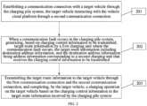
- FIG. 2 is a schematic flowchart of a charging control method according to an embodiment of the present disclosure.
- the method is applied in a charging control system.
- the charging control system includes a pile cloud platform, a charging pile system, and a vehicle cloud platform interacting with the pile cloud platform through a first communication connection.
- the method specifically includes actions in blocks S201 to S203 in a process of charging the target vehicle by the charging pile system.
- a communication connection is established with a target vehicle through a charging management unit in the charging pile system.
- the target vehicle interacts with the vehicle cloud platform through a second communication connection.
- target route information is generated by a first charging unit where the communication fault occurs based on charging control information to be transmitted.
- the target route information includes destination address information, and the destination address information is address information corresponding to a second charging unit that receives the charging control information to be transmitted.
- the target route information is transmitted to the target vehicle through the first communication connection and the second communication connection, and a charging operation is completed by the target vehicle on the target vehicle based on the charging control information in the target route information received by the charging pile system.
- the action of transmitting the target route information to the target vehicle through the first communication connection and the second communication connection further includes: transmitting, by the target vehicle, reverse transmission route information of the target route information received by the first charging unit to the first charging unit through the first communication connection and the second communication connection.
- the reverse route information process is used for performing information interaction.
- the charging pile system includes a plurality of parallel second charging units and a plurality of parallel charging management units; and the process of charging the target vehicle by the charging pile system further includes: when one second charging unit fails simultaneously with a corresponding first charging unit and a corresponding charging management unit in the charging pile system, generating, by the second charging unit where a communication fault occurs, first target route information based on the charging control information to be transmitted, the first target route information including the destination address information and fault request information, and the fault request information being address information corresponding to the second charging unit where the communication fault occurs; and transmitting, by a normal second charging unit, the first target route information to the target vehicle through the second communication connection and the first communication connection, transmitting, by the target vehicle, the first target route information to a corresponding first charging unit corresponding to the destination address information through the plurality of charging management units, and completing, by the first charging unit, the charging operation on the target vehicle based on the charging control information in the first target route information.
- the process of charging the target vehicle by the charging pile system further includes: transmitting the first target route information to the pile cloud platform through the target vehicle, the second communication connection, and the first communication connection, and performing fault communication positioning by the pile cloud platform.
- the process of charging the target vehicle by the charging pile system further includes: generating, by a first charging unit in the charging pile system, second route information based on the charging control information to be transmitted when a communication fault occurs between the charging pile system and the pile cloud platform, the second route information including charging pile charging monitoring information and charging pile charging state information; transmitting the second route information to the pile cloud platform through the target vehicle, the first communication connection, and the second communication connection, and generating, by the pile cloud platform, charging authorization information based on the second route information; and transmitting the charging authorization information to the target vehicle through the first communication connection and the second communication connection, transmitting, by the target vehicle, the charging authorization information to the charging pile system through the plurality of charging management units, and completing the charging operation on the target vehicle by the charging pile system.
- the first charging unit is a station monitoring unit (SMU), and the second charging unit is a power management unit (PMU).
- the station monitoring unit mainly performs management of the entire station (such as charging scheduling, service settlement, and environment detection control of the station).
- the power management unit mainly achieves functions of power management, thermal management, electrical monitoring, environmental monitoring, power distribution, energy control, and the like.
- a charging management unit (CMU) mainly achieves functions of vehicle communication, charging control, liquid cooling gun cooling system control, man-machine interaction control, and the like.
- the pile cloud platform is further connected to the charging APP, and the vehicle cloud platform is connected to the vehicle APP.
- the charging APP is used for displaying vehicle pile information of the pile cloud platform
- the vehicle APP is used for displaying charging information of the vehicle cloud platform.
- the annular vehicle charging system is formed by the pile cloud platform, the vehicle cloud platform, the charging pile system, and the vehicle.
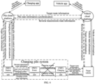
- FIG. 3 is a schematic diagram of an information flow during normal operation of a charging pile according to an embodiment of the present disclosure.
- the pile cloud platform transmits normal charging control information to the station monitoring unit in the charging pile system
- the station monitoring unit collects the charging control information and reports information of the charging pile system to the pile cloud platform in real-time to realize information interaction between the charging pile system and the pile cloud platform
- the charging control information is interacted with vehicle-pile charging timing sequence of the target vehicle by the charging management unit through a standard charging protocol.
- the charging state information of the target vehicle is transmitted to the vehicle cloud platform by the target vehicle.
- the vehicle cloud platform and the pile cloud platform synchronize the vehicle pile state information based on the vehicle charging demand. Moreover, the charging APP connected to the pile cloud platform and the vehicle APP connected to the vehicle cloud platform display the charging state information and other information.
- the charging operation on the target vehicle is achieved by the units of the charging pile system based on the charging control information in the charging information interaction.
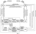
- FIG. 4 is a schematic diagram of an information flow when a communication fault occurs between a power management unit and a charging management unit in a charging pile system according to an embodiment of the present disclosure.
- the target route information is generated based on the information to be transmitted by the power management unit to the charging management unit.
- the target route information in the drawings refers to the route information transmitted by the power management unit to the charging management unit, and the reverse transmission route information refers to the route information to be transmitted by the charging management unit to the power management unit.
- the information format may be selected as: normal information/clockwise route/counterclockwise route/requesting bypass route (e.g., PMU-A requests PMU-B to perform bypass information route) Destination address An address of a target ECU that the route information needs to reach. Source address An address of the ECU first initiating the route information Information length A total length of information requiring the route (unit: byte) Route information Information needs to be routed (which is mainly interaction information or control information required for normal charging)
- the charging pile system includes the plurality of parallel second charging units and the plurality of parallel charging management units, and one second charging unit fails simultaneously with the corresponding first charging unit and the corresponding charging management unit in the charging pile system.
- FIG. 5 is a schematic diagram of a communication information flow when a power management unit (PMU-A) fails simultaneously with a station monitoring unit and a charging management unit according to an embodiment of the present disclosure.
- the first target route information is generated based on the information to be transmitted by the PMU-A.
- the first target route information includes the fault request information.
- the fault request information of the first target route information is transmitted to the pile cloud platform through the PMU-B, the pile cloud platform positions the faulty second charging unit, and information interaction of the PMU-B is consistent with information interaction thereof in FIG. 4 .
- the charging management unit (CMU-A1) since the power management unit (PMU-A) fails simultaneously with the station monitoring unit and the charging management unit, the charging management unit (CMU-A1) also generates the route information based on the information to be transmitted, thereby completing the interaction of the charging control information. However, at this time, the target vehicle 1 is in an uncharged state due to the loss of the control of the power management unit on the charging information.
- FIG. 6 is a schematic diagram of an information flow when a communication fault occurs between a pile cloud platform and a charging pile system according to an embodiment of the present disclosure.
- the station monitoring unit in the charging pile system packages the information to be transmitted into the second target route information, and transmits the second target route information to the pile cloud platform through the target vehicle, the first communication connection, and the second communication connection.
- the charging authorization information is generated by the pile cloud platform based on the second target route information.
- the charging authorization information is transmitted by the pile cloud platform to the target vehicle through the first communication connection and the second communication connection.
- the charging authorization information is transmitted by the target vehicle to the charging pile system through the charging management unit. Therefore, the charging operation on the target vehicle is completed by the charging pile system.
- the target route information is generated by the first charging unit where the communication fault occurs based on the charging control information to be transmitted.
- the target route information includes the destination address information, and the destination address information is the address information corresponding to the second charging unit that receives the charging control information to be transmitted.
- the target route information is transmitted to the target vehicle through the first communication connection and the second communication connection, and is transmitted by the target vehicle to the second charging unit corresponding to the destination address information, enabling the second charging unit to complete the charging operation on the target vehicle based on the charging control information in the target route information.
- the charging process of the vehicle may also be completed. Moreover, it is possible to improve reliability and robustness of the charging system and accurate positioning of a fault point.
- FIG. 7 is a schematic diagram of a charging control system according to an embodiment of the present disclosure, which specifically includes: a communication connection module 10 configured to establish a communication connection with a target vehicle through the charging pile system in a process of charging the target vehicle by the charging pile system, the target vehicle interacting with the vehicle cloud platform through a second communication connection; a route information determination module 20 configured to, when a communication fault occurs in the charging pile system, generate, based on charging control information to be transmitted, target route information by a first charging unit where the communication fault occurs, the target route information including destination address information, and the destination address information being address information corresponding to a second charging unit that receives the charging control information to be transmitted; and a charging control module 30 configured to transmit the target route information to the target vehicle through the first communication connection and the second communication connection, and complete, by the target
- the charging control module 30 further includes: a reverse transmission route module configured to transmit, by the target vehicle, reverse transmission route information of the target route information received by the first charging unit to the first charging unit through the first communication connection and the second communication connection.
- the reverse route information process is used for performing information interaction.
- the charging pile system includes a plurality of parallel second charging units and a plurality of parallel charging management units; and the process of charging the target vehicle by the charging pile system further includes: a first target route information determination module configured to when one second charging unit fails simultaneously with a corresponding first charging unit and a corresponding charging management unit in the charging pile system, generate, by the second charging unit where a communication fault occurs, first target route information based on the charging control information to be transmitted, the first target route information including the destination address information and fault request information, and the fault request information being address information corresponding to the second charging unit where the communication fault occurs; and a first charging control module configured to transmit, by a normal second charging unit, the first target route information to the target vehicle through the second communication connection and the first communication connection, transmitting, by the target vehicle, the first target route information to a first charging unit corresponding to the destination address information through the plurality of charging management units, and completing, by the first charging unit, the charging operation on the target vehicle based on charging control information in the first target route information.
- the process of charging the target vehicle by the charging pile system further includes: a fault positioning module configured to transmit the first target route information to the pile cloud platform through the target vehicle, the second communication connection, and the first communication connection, and perform fault communication positioning by the pile cloud platform.
- the process of charging the target vehicle by the charging pile system further includes: a second route information determination module configured to generate, by a first charging unit in the charging pile system, second route information based on the charging control information to be transmitted when a communication fault occurs between the charging pile system and the pile cloud platform, the second route information including charging pile charging monitoring information and charging pile charging state information; a charging authorization information module configured to transmit the second route information to the pile cloud platform through the target vehicle, the first communication connection, and the second communication connection, and generating, by the pile cloud platform, charging authorization information based on the second route information; and a second charging control module configured to transmit the charging authorization information to the target vehicle through the first communication connection and the second communication connection, transmitting, by the target vehicle, the charging authorization information to the charging pile system through the plurality of charging management units, and completing the charging operation on the target vehicle by the charging pile system.
- a second route information determination module configured to generate, by a first charging unit in the charging pile system, second route information based on the charging control information to be transmitted when a communication fault
- the embodiments of the present disclosure further provide a storage medium, when loaded and executed, implementing the charging control method as described above.
Landscapes
- Engineering & Computer Science (AREA)
- Power Engineering (AREA)
- Transportation (AREA)
- Mechanical Engineering (AREA)
- Computer Networks & Wireless Communication (AREA)
- Signal Processing (AREA)
- Health & Medical Sciences (AREA)
- Medical Informatics (AREA)
- General Health & Medical Sciences (AREA)
- Computing Systems (AREA)
- Computer Security & Cryptography (AREA)
- Life Sciences & Earth Sciences (AREA)
- Sustainable Development (AREA)
- Sustainable Energy (AREA)
- Electric Propulsion And Braking For Vehicles (AREA)
- Charge And Discharge Circuits For Batteries Or The Like (AREA)
Abstract
Description
- The present disclosure relates to the technical field of charging electric vehicles by charging piles, and in particular, to a charging control method and system, and a storage medium.
- With the progress of the times, the number of charging units in a current charging pile system is increasing, and a network structure is becoming more complex. A charging station may have dozens or even hundreds of charging units. A charging function may be jointly achieved by adopting a layered structure and involving multilayered network transmission and conversion.
- However, in traditional solutions, a communication fault or a network fault occurring in any charging unit within a transmission link may cause the entire charging system to fail to work. Reliability and robustness of the entire system are both poor, especially in charging systems with a large number of charging units and complex networks. In existing solutions, the charging system is connected to a cloud platform through a single link. When a communication outage occurs between the charging system and the cloud platform, it may also result in the inability to settle charging of the system, leading to charging failures.
- To solve the existing problems in the related art, an embodiment of the present disclosure provides a charging control method and system, and a storage medium. The technical solution is described below.
- One embodiment provideds a charging control method, applied in a charging control system including a pile cloud platform, a charging pile system, and a vehicle cloud platform interacting with the pile cloud platform through a first communication connection. The method includes, in a process of charging the target vehicle by the charging pile system: establishing a communication connection with a target vehicle through the charging pile system, the target vehicle interacts with the vehicle cloud platform through a second communication connection; when a communication fault occurs in the charging pile system, generating, based on charging control information to be transmitted, target route information by a first charging unit where the communication fault occurs, the target route information includes destination address information, and the destination address information is address information corresponding to a second charging unit that receives the charging control information to be transmitted; and transmitting the target route information to the target vehicle through the first communication connection and the second communication connection, and completing, by the target vehicle, a charging operation on the target vehicle based on the charging control information in the target route information received by the charging pile system.
- Another embodiment provides a charging control system, including: a pile cloud platform; a charging pile system; a vehicle cloud platform interacting with the pile cloud platform through a first communication connection; a communication connection module configured to establish a communication connection with a target vehicle through the charging pile system in a process of charging the target vehicle by the charging pile system, the target vehicle interacts with the vehicle cloud platform through a second communication connection; a route information determination module configured to, when a communication fault occurs in the charging pile system, generate, based on charging control information to be transmitted, target route information by a first charging unit where the communication fault occurs, the target route information includes destination address information, and the destination address information is address information corresponding to a second charging unit that receives the charging control information to be transmitted; and a charging control module configured to transmit the target route information to the target vehicle through the first communication connection and the second communication connection, and complete, by the target vehicle, a charging operation on the target vehicle based on the charging control information in the target route information received by the charging pile system.
- Correspondingly, the charging control module further includes: a reverse transmission route module configured to transmit, by the target vehicle, reverse transmission route information of the target route information received by the first charging unit to the first charging unit through the first communication connection and the second communication connection, the reverse route information process is used for performing information interaction.
- Correspondingly, the charging pile system includes a plurality of parallel second charging units and a plurality of parallel charging management units; and the process of charging the target vehicle by the charging pile system further includes: a first target route information determination module configured to when one of the plurality of parallel second charging units fails simultaneously with a corresponding first charging unit and a corresponding charging management unit in the charging pile system, generate, by the second charging unit where a communication fault occurs, first target route information based on the charging control information to be transmitted, the first target route information includes the destination address information and fault request information, and the fault request information is address information corresponding to the second charging unit where the communication fault occurs; and a first charging control module configured to transmit, by a normal second charging unit, the first target route information to the target vehicle through the second communication connection and the first communication connection, transmitting, by the target vehicle, the first target route information to a first charging unit corresponding to the destination address information through the plurality of charging management units, and completing, by the first charging unit, the charging operation on the target vehicle based on charging control information in the first target route information.
- Correspondingly, the process of charging the target vehicle by the charging pile system further includes: a fault positioning module configured to transmit the first target route information to the pile cloud platform through the target vehicle, the second communication connection, and the first communication connection, and performing fault communication positioning by the pile cloud platform.
- Correspondingly, the process of charging the target vehicle by the charging pile system further includes: a second route information determination module configured to generate, by a first charging unit in the charging pile system, second route information based on the charging control information to be transmitted when a communication fault occurs between the charging pile system and the pile cloud platform, the second route information including charging pile charging monitoring information and charging pile charging state information; a charging authorization information module configured to transmit the second route information to the pile cloud platform through the target vehicle, the first communication connection, and the second communication connection, and generating, by the pile cloud platform, charging authorization information based on the second route information; and a second charging control module configured to transmit the charging authorization information to the target vehicle through the first communication connection and the second communication connection, transmitting, by the target vehicle, the charging authorization information to the charging pile system through the plurality of charging management units, and completing the charging operation on the target vehicle by the charging pile system.
- The other embodiment provides a storage medium, storing at least one instruction, at least one section of a program, a code set, or an instruction set. The at least one instruction, the at least one section of the program, code set, or instruction set, when loaded and executed by a processor, implement the charging control method as described above.
- The present disclosure provides a charging control method and system, and a storage medium, which have the following technical effects.
- According to embodiments of the present disclosure, by establishing the communication connection with the target vehicle through the charging management unit in the charging pile system, when the communication fault occurs in the charging pile system, the target route information is generated by the first charging unit where the communication fault occurs based on the charging control information to be transmitted. The target route information includes the destination address information, and the destination address information is the address information corresponding to the second charging unit that receives the charging control information to be transmitted. The target route information is transmitted to the target vehicle through the first communication connection and the second communication connection, and is transmitted by the target vehicle to the second charging unit corresponding to the destination address information, enabling the second charging unit to complete the charging operation on the target vehicle based on the charging control information in the target route information. According to the technical solution, when the communication fault occurs in the charging unit, the charging process of the vehicle may also be completed. Moreover, it is possible to improve reliability and robustness of the charging system and accurate positioning of the fault point.
- In order to clearly explain technical solutions of the embodiments of the present disclosure or in the related art, accompanying drawings used in the description of the embodiments or the related art are briefly described below. Obviously, the accompanying drawings as described below are merely some embodiments of the present disclosure. Based on structures illustrated in these drawings, other accompanying drawings may be obtained by those of ordinary skill in the art without creative effort.
-
FIG. 1 is a diagram illustrating an application environment of a charging control method according to an embodiment of the present disclosure. -
FIG. 2 is a schematic flowchart of a charging control method according to an embodiment of the present disclosure. -
FIG. 3 is a schematic diagram of an information flow during normal operation of a charging pile according to an embodiment of the present disclosure. -
FIG. 4 is a schematic diagram of an information flow when a communication fault occurs between a power management unit and a charging management unit in a charging pile system according to an embodiment of the present disclosure. -
FIG. 5 is a schematic diagram of a communication information flow when a power management unit (PMU-A) fails simultaneously with a station monitoring unit and a charging management unit according to an embodiment of the present disclosure. -
FIG. 6 is a schematic diagram of an information flow when a communication fault occurs between a pile cloud platform and a charging pile system according to an embodiment of the present disclosure. -
FIG. 7 is a schematic diagram of a charging control system according to an embodiment of the present disclosure. - Technical solutions according to embodiments of the present disclosure will be clearly and completely described below in combination with accompanying drawings of the embodiments of the present disclosure. Obviously, the embodiments described below are only a part, rather than all, of the embodiments of the present disclosure. On a basis of the embodiments in the present disclosure, all other embodiments obtained by those of ordinary skill in the art without creative labor shall fall within the scope of the present disclosure.
-
FIG. 1 is an application environment of a charging control method according to an embodiment of the present disclosure. The application environment is specifically applied in an Internet of Vehicles system for charging a vehicle by a charging pile. The system mainly includes a pile cloud platform, a charging pile system, a vehicle cloud platform, which form an annular charging network together with the vehicle. The pile cloud platform is connected to a charging APP, and data information received by the pile cloud platform is displayed by the charging APP. The vehicle cloud platform is connected to a vehicle APP, and data information received by the vehicle cloud platform is displayed by the vehicle APP. - The charging control method provided by the embodiments of the present disclosure will be described in detail below with reference to the application environment illustrated in
FIG. 1 . -
FIG. 2 is a schematic flowchart of a charging control method according to an embodiment of the present disclosure. In some embodiments, as illustrated inFIG. 2 , the method is applied in a charging control system. The charging control system includes a pile cloud platform, a charging pile system, and a vehicle cloud platform interacting with the pile cloud platform through a first communication connection. The method specifically includes actions in blocks S201 to S203 in a process of charging the target vehicle by the charging pile system. - At block S201, a communication connection is established with a target vehicle through a charging management unit in the charging pile system. The target vehicle interacts with the vehicle cloud platform through a second communication connection.
- At block S202, when a communication fault occurs in the charging pile system, target route information is generated by a first charging unit where the communication fault occurs based on charging control information to be transmitted. The target route information includes destination address information, and the destination address information is address information corresponding to a second charging unit that receives the charging control information to be transmitted.
- At block S203, the target route information is transmitted to the target vehicle through the first communication connection and the second communication connection, and a charging operation is completed by the target vehicle on the target vehicle based on the charging control information in the target route information received by the charging pile system.
- Further, the action of transmitting the target route information to the target vehicle through the first communication connection and the second communication connection further includes: transmitting, by the target vehicle, reverse transmission route information of the target route information received by the first charging unit to the first charging unit through the first communication connection and the second communication connection. The reverse route information process is used for performing information interaction.
- Further, the charging pile system includes a plurality of parallel second charging units and a plurality of parallel charging management units; and the process of charging the target vehicle by the charging pile system further includes: when one second charging unit fails simultaneously with a corresponding first charging unit and a corresponding charging management unit in the charging pile system, generating, by the second charging unit where a communication fault occurs, first target route information based on the charging control information to be transmitted, the first target route information including the destination address information and fault request information, and the fault request information being address information corresponding to the second charging unit where the communication fault occurs; and transmitting, by a normal second charging unit, the first target route information to the target vehicle through the second communication connection and the first communication connection, transmitting, by the target vehicle, the first target route information to a corresponding first charging unit corresponding to the destination address information through the plurality of charging management units, and completing, by the first charging unit, the charging operation on the target vehicle based on the charging control information in the first target route information.
- Further, the process of charging the target vehicle by the charging pile system further includes: transmitting the first target route information to the pile cloud platform through the target vehicle, the second communication connection, and the first communication connection, and performing fault communication positioning by the pile cloud platform.
- Further, the process of charging the target vehicle by the charging pile system further includes: generating, by a first charging unit in the charging pile system, second route information based on the charging control information to be transmitted when a communication fault occurs between the charging pile system and the pile cloud platform, the second route information including charging pile charging monitoring information and charging pile charging state information; transmitting the second route information to the pile cloud platform through the target vehicle, the first communication connection, and the second communication connection, and generating, by the pile cloud platform, charging authorization information based on the second route information; and transmitting the charging authorization information to the target vehicle through the first communication connection and the second communication connection, transmitting, by the target vehicle, the charging authorization information to the charging pile system through the plurality of charging management units, and completing the charging operation on the target vehicle by the charging pile system.
- In this embodiment of the present disclosure, the first charging unit is a station monitoring unit (SMU), and the second charging unit is a power management unit (PMU). The station monitoring unit mainly performs management of the entire station (such as charging scheduling, service settlement, and environment detection control of the station). The power management unit mainly achieves functions of power management, thermal management, electrical monitoring, environmental monitoring, power distribution, energy control, and the like. A charging management unit (CMU) mainly achieves functions of vehicle communication, charging control, liquid cooling gun cooling system control, man-machine interaction control, and the like.
- In the charging control system, the pile cloud platform is further connected to the charging APP, and the vehicle cloud platform is connected to the vehicle APP. The charging APP is used for displaying vehicle pile information of the pile cloud platform, and the vehicle APP is used for displaying charging information of the vehicle cloud platform. In the whole Internet of Vehicles charging system, the annular vehicle charging system is formed by the pile cloud platform, the vehicle cloud platform, the charging pile system, and the vehicle. When a communication outage occurs in the charging pile system or the charging pile system loses communication with the pile cloud platform, charging of the target vehicle by the charging pile is not affected, which enhances stability and reliability of the charging system.
-
FIG. 3 is a schematic diagram of an information flow during normal operation of a charging pile according to an embodiment of the present disclosure. When the interior of charging pile system, the charging pile system, and the pile cloud platform are all communicated normally, the pile cloud platform transmits normal charging control information to the station monitoring unit in the charging pile system, the station monitoring unit collects the charging control information and reports information of the charging pile system to the pile cloud platform in real-time to realize information interaction between the charging pile system and the pile cloud platform, and the charging control information is interacted with vehicle-pile charging timing sequence of the target vehicle by the charging management unit through a standard charging protocol. The charging state information of the target vehicle is transmitted to the vehicle cloud platform by the target vehicle. The vehicle cloud platform and the pile cloud platform synchronize the vehicle pile state information based on the vehicle charging demand. Moreover, the charging APP connected to the pile cloud platform and the vehicle APP connected to the vehicle cloud platform display the charging state information and other information. The charging operation on the target vehicle is achieved by the units of the charging pile system based on the charging control information in the charging information interaction. - As an example of the communication outage in the charging pile system, a communication fault occurs between the second charging unit and the charging management unit.
FIG. 4 is a schematic diagram of an information flow when a communication fault occurs between a power management unit and a charging management unit in a charging pile system according to an embodiment of the present disclosure. InFIG. 4 , the target route information is generated based on the information to be transmitted by the power management unit to the charging management unit. The target route information in the drawings refers to the route information transmitted by the power management unit to the charging management unit, and the reverse transmission route information refers to the route information to be transmitted by the charging management unit to the power management unit. In addition, normal information interaction is also performed while the route information is transmitted, and the charging operation on the target vehicle is completed by the units of the charging pile system based on the charging control information in the target route information. The content contained in the target route information is illustrated in the following table:Information format The information format may be selected as: normal information/clockwise route/counterclockwise route/requesting bypass route (e.g., PMU-A requests PMU-B to perform bypass information route) Destination address An address of a target ECU that the route information needs to reach. Source address An address of the ECU first initiating the route information Information length A total length of information requiring the route (unit: byte) Route information Information needs to be routed (which is mainly interaction information or control information required for normal charging) - The charging pile system includes the plurality of parallel second charging units and the plurality of parallel charging management units, and one second charging unit fails simultaneously with the corresponding first charging unit and the corresponding charging management unit in the charging pile system. For example,
FIG. 5 is a schematic diagram of a communication information flow when a power management unit (PMU-A) fails simultaneously with a station monitoring unit and a charging management unit according to an embodiment of the present disclosure. InFIG. 5 , the first target route information is generated based on the information to be transmitted by the PMU-A. The first target route information includes the fault request information. The fault request information of the first target route information is transmitted to the pile cloud platform through the PMU-B, the pile cloud platform positions the faulty second charging unit, and information interaction of the PMU-B is consistent with information interaction thereof inFIG. 4 . - In
FIG. 5 , since the power management unit (PMU-A) fails simultaneously with the station monitoring unit and the charging management unit, the charging management unit (CMU-A1) also generates the route information based on the information to be transmitted, thereby completing the interaction of the charging control information. However, at this time, thetarget vehicle 1 is in an uncharged state due to the loss of the control of the power management unit on the charging information. - When the communication fault occurs between the charging pile system and the pile cloud platform,
FIG. 6 is a schematic diagram of an information flow when a communication fault occurs between a pile cloud platform and a charging pile system according to an embodiment of the present disclosure. The station monitoring unit in the charging pile system packages the information to be transmitted into the second target route information, and transmits the second target route information to the pile cloud platform through the target vehicle, the first communication connection, and the second communication connection. The charging authorization information is generated by the pile cloud platform based on the second target route information. The charging authorization information is transmitted by the pile cloud platform to the target vehicle through the first communication connection and the second communication connection. The charging authorization information is transmitted by the target vehicle to the charging pile system through the charging management unit. Therefore, the charging operation on the target vehicle is completed by the charging pile system. - According to embodiments of the present disclosure, by establishing the communication connection with the target vehicle through the charging management unit in the charging pile system, when the communication fault occurs in the charging pile system, the target route information is generated by the first charging unit where the communication fault occurs based on the charging control information to be transmitted. The target route information includes the destination address information, and the destination address information is the address information corresponding to the second charging unit that receives the charging control information to be transmitted. The target route information is transmitted to the target vehicle through the first communication connection and the second communication connection, and is transmitted by the target vehicle to the second charging unit corresponding to the destination address information, enabling the second charging unit to complete the charging operation on the target vehicle based on the charging control information in the target route information. According to the technical solution, when the communication fault occurs in the charging unit, the charging process of the vehicle may also be completed. Moreover, it is possible to improve reliability and robustness of the charging system and accurate positioning of a fault point.
- The embodiments of the present disclosure further provide a charging control system. The charging control system includes: a pile cloud platform, a charging pile system, and a vehicle cloud platform interacting with the pile cloud platform through a first communication connection.
FIG. 7 is a schematic diagram of a charging control system according to an embodiment of the present disclosure, which specifically includes: acommunication connection module 10 configured to establish a communication connection with a target vehicle through the charging pile system in a process of charging the target vehicle by the charging pile system, the target vehicle interacting with the vehicle cloud platform through a second communication connection; a routeinformation determination module 20 configured to, when a communication fault occurs in the charging pile system, generate, based on charging control information to be transmitted, target route information by a first charging unit where the communication fault occurs, the target route information including destination address information, and the destination address information being address information corresponding to a second charging unit that receives the charging control information to be transmitted; and a chargingcontrol module 30 configured to transmit the target route information to the target vehicle through the first communication connection and the second communication connection, and complete, by the target vehicle, a charging operation on the target vehicle based on the charging control information in the target route information received by the charging pile system. - Further, the charging
control module 30 further includes: a reverse transmission route module configured to transmit, by the target vehicle, reverse transmission route information of the target route information received by the first charging unit to the first charging unit through the first communication connection and the second communication connection. The reverse route information process is used for performing information interaction. - Further, the charging pile system includes a plurality of parallel second charging units and a plurality of parallel charging management units; and the process of charging the target vehicle by the charging pile system further includes: a first target route information determination module configured to when one second charging unit fails simultaneously with a corresponding first charging unit and a corresponding charging management unit in the charging pile system, generate, by the second charging unit where a communication fault occurs, first target route information based on the charging control information to be transmitted, the first target route information including the destination address information and fault request information, and the fault request information being address information corresponding to the second charging unit where the communication fault occurs; and a first charging control module configured to transmit, by a normal second charging unit, the first target route information to the target vehicle through the second communication connection and the first communication connection, transmitting, by the target vehicle, the first target route information to a first charging unit corresponding to the destination address information through the plurality of charging management units, and completing, by the first charging unit, the charging operation on the target vehicle based on charging control information in the first target route information.
- Further, the process of charging the target vehicle by the charging pile system further includes: a fault positioning module configured to transmit the first target route information to the pile cloud platform through the target vehicle, the second communication connection, and the first communication connection, and perform fault communication positioning by the pile cloud platform.
- Further, the process of charging the target vehicle by the charging pile system further includes: a second route information determination module configured to generate, by a first charging unit in the charging pile system, second route information based on the charging control information to be transmitted when a communication fault occurs between the charging pile system and the pile cloud platform, the second route information including charging pile charging monitoring information and charging pile charging state information; a charging authorization information module configured to transmit the second route information to the pile cloud platform through the target vehicle, the first communication connection, and the second communication connection, and generating, by the pile cloud platform, charging authorization information based on the second route information; and a second charging control module configured to transmit the charging authorization information to the target vehicle through the first communication connection and the second communication connection, transmitting, by the target vehicle, the charging authorization information to the charging pile system through the plurality of charging management units, and completing the charging operation on the target vehicle by the charging pile system.
- Regarding the system according to any of the above embodiments, a specific manner in which each module performs operations has been described in detail in the embodiments of the method, and detailed description will be omitted here.
- The embodiments of the present disclosure further provide a storage medium, when loaded and executed, implementing the charging control method as described above.
- While the specific embodiments of the present disclosure have been described above, the protect scope of the present disclosure is not limited to these embodiments. Various variants and alternatives can be easily conceived by any of those skilled in the art without departing from the technical scope of the present disclosure. Therefore, these variants and alternatives are to be encompassed by the protect scope of present disclosure as defined by the claims as attached.
Claims (10)
- A charging control method, applied to a charging control system comprising a pile cloud platform, a charging pile system, and a vehicle cloud platform interacting with the pile cloud platform through a first communication connection, the method comprising, in a process of charging a target vehicle by the charging pile system:establishing a communication connection with the target vehicle through the charging pile system, the target vehicle interacting with the vehicle cloud platform through a second communication connection;when a communication fault occurs in the charging pile system, generating, based on charging control information to be transmitted, target route information by a first charging unit where the communication fault occurs, the target route information comprising destination address information, and the destination address information being address information corresponding to a second charging unit that receives the charging control information to be transmitted; andtransmitting the target route information to the target vehicle through the first communication connection and the second communication connection, and completing, by the target vehicle, a charging operation on the target vehicle based on the charging control information in the target route information received by the charging pile system.
- The charging control method according to claim 1, wherein said transmitting the target route information to the target vehicle through the first communication connection and the second communication connection further comprises:
transmitting, by the target vehicle, reverse transmission route information of the target route information received by the first charging unit to the first charging unit through the first communication connection and the second communication connection, the reverse route information process being used for performing information interaction. - The charging control method according to claim 1, whereinthe charging pile system comprises a plurality of parallel second charging units and a plurality of parallel charging management units; andthe process of charging the target vehicle by the charging pile system further comprises:when one of the plurality of parallel second charging units fails simultaneously with a corresponding first charging unit and a corresponding charging management unit in the charging pile system, generating, by the second charging unit where a communication fault occurs, first target route information based on the charging control information to be transmitted, the first target route information comprising the destination address information and fault request information, and the fault request information being address information corresponding to the second charging unit where the communication fault occurs; andtransmitting, by a normal second charging unit, the first target route information to the target vehicle through the second communication connection and the first communication connection, transmitting, by the target vehicle, the first target route information to a first charging unit corresponding to the destination address information through the plurality of charging management units, and completing, by the first charging unit, the charging operation on the target vehicle based on the charging control information in the first target route information.
- The charging control method according to claim 3, wherein the process of charging the target vehicle by the charging pile system further comprises:
transmitting the first target route information to the pile cloud platform through the target vehicle, the second communication connection, and the first communication connection, and performing fault communication positioning by the pile cloud platform. - The charging control method according to claim 3, wherein the process of charging the target vehicle by the charging pile system further comprises:generating, by a first charging unit in the charging pile system, second route information based on the charging control information to be transmitted when a communication fault occurs between the charging pile system and the pile cloud platform, the second route information comprising charging pile charging monitoring information and charging pile charging state information;transmitting the second route information to the pile cloud platform through the target vehicle, the first communication connection, and the second communication connection, and generating, by the pile cloud platform, charging authorization information based on the second route information; andtransmitting the charging authorization information to the target vehicle through the first communication connection and the second communication connection, transmitting, by the target vehicle, the charging authorization information to the charging pile system through the plurality of charging management units, and completing the charging operation on the target vehicle by the charging pile system.
- A charging control system, comprising:a pile cloud platform;a charging pile system;a vehicle cloud platform interacting with the pile cloud platform through a first communication connection;a communication connection module configured to establish a communication connection with a target vehicle through the charging pile system in a process of charging the target vehicle by the charging pile system, the target vehicle interacting with the vehicle cloud platform through a second communication connection;a route information determination module configured to, when a communication fault occurs in the charging pile system, generate, based on charging control information to be transmitted, target route information by a first charging unit where the communication fault occurs, the target route information comprising destination address information, and the destination address information being address information corresponding to a second charging unit that receives the charging control information to be transmitted; anda charging control module configured to transmit the target route information to the target vehicle through the first communication connection and the second communication connection, and complete, by the target vehicle, a charging operation on the target vehicle based on the charging control information in the target route information received by the charging pile system.
- The charging control system according to claim 6, wherein the charging control module further comprises:
a reverse transmission route module configured to transmit, by the target vehicle, reverse transmission route information of the target route information received by the first charging unit to the first charging unit through the first communication connection and the second communication connection, the reverse route information process being used for performing information interaction. - The charging control system according to claim 6, whereinthe charging pile system comprises a plurality of parallel second charging units and a plurality of parallel charging management units; andthe process of charging the target vehicle by the charging pile system further comprises:a first target route information determination module configured to when one of the plurality of parallel second charging units fails simultaneously with a corresponding first charging unit and a corresponding charging management unit in the charging pile system, generate, by the second charging unit where a communication fault occurs, first target route information based on the charging control information to be transmitted, the first target route information comprising the destination address information and fault request information, and the fault request information being address information corresponding to the second charging unit where the communication fault occurs; anda first charging control module configured to transmit, by a normal second charging unit, the first target route information to the target vehicle through the second communication connection and the first communication connection, transmitting, by the target vehicle, the first target route information to a first charging unit corresponding to the destination address information through the plurality of charging management units, and completing, by the first charging unit, the charging operation on the target vehicle based on charging control information in the first target route information.
- The charging control system according to claim 6, wherein the process of charging the target vehicle by the charging pile system further comprises:a second route information determination module configured to generate, by a first charging unit in the charging pile system, second route information based on the charging control information to be transmitted when a communication fault occurs between the charging pile system and the pile cloud platform, the second route information comprising charging pile charging monitoring information and charging pile charging state information;a charging authorization information module configured to transmit the second route information to the pile cloud platform through the target vehicle, the first communication connection, and the second communication connection, and generating, by the pile cloud platform, charging authorization information based on the second route information; anda second charging control module configured to transmit the charging authorization information to the target vehicle through the first communication connection and the second communication connection, transmitting, by the target vehicle, the charging authorization information to the charging pile system through the plurality of charging management units, and completing the charging operation on the target vehicle by the charging pile system.
- A storage medium, when executed, implementing the charging control method according to any one of claims 1 to 5.
Applications Claiming Priority (1)
| Application Number | Priority Date | Filing Date | Title |
|---|---|---|---|
| PCT/CN2021/093987 WO2022241585A1 (en) | 2021-05-16 | 2021-05-16 | Charging control method and system, and storage medium |
Publications (4)
| Publication Number | Publication Date |
|---|---|
| EP4283820A1 true EP4283820A1 (en) | 2023-11-29 |
| EP4283820A4 EP4283820A4 (en) | 2024-05-15 |
| EP4283820C0 EP4283820C0 (en) | 2025-11-26 |
| EP4283820B1 EP4283820B1 (en) | 2025-11-26 |
Family
ID=84140934
Family Applications (1)
| Application Number | Title | Priority Date | Filing Date |
|---|---|---|---|
| EP21940044.7A Active EP4283820B1 (en) | 2021-05-16 | 2021-05-16 | Charging control method and system, and storage medium |
Country Status (3)
| Country | Link |
|---|---|
| EP (1) | EP4283820B1 (en) |
| CN (1) | CN116964890A (en) |
| WO (1) | WO2022241585A1 (en) |
Families Citing this family (2)
| Publication number | Priority date | Publication date | Assignee | Title |
|---|---|---|---|---|
| CN119199366B (en) * | 2024-11-27 | 2026-02-03 | 江苏起风电力科技有限公司 | Charging pile fault detection system and method based on Internet of things |
| CN119858472B (en) * | 2025-01-24 | 2025-10-14 | 长城汽车股份有限公司 | Vehicle charging method, vehicle charging device and vehicle automatic charging system |
Family Cites Families (6)
| Publication number | Priority date | Publication date | Assignee | Title |
|---|---|---|---|---|
| US8611824B2 (en) * | 2009-12-28 | 2013-12-17 | Toyota Jidosha Kabushiki Kaisha | Vehicle, communication system for vehicle, and communication controlling method for vehicle |
| JP2013236205A (en) * | 2012-05-08 | 2013-11-21 | Toyota Industries Corp | Charging control information communication system and method |
| CN107231430B (en) * | 2017-06-22 | 2021-06-08 | 华为技术有限公司 | Charging pile, charging pile networking structure and charging pile management method |
| CN110370976B (en) * | 2019-07-25 | 2021-04-20 | 一能充电科技(深圳)有限责任公司 | New energy automobile charging pile communication method based on cloud platform |
| CN111497673A (en) * | 2020-04-16 | 2020-08-07 | 西安艾润物联网技术服务有限责任公司 | Charging pile management method, mobile terminal, charging pile, cloud platform and medium |
| CN112428863A (en) * | 2020-11-25 | 2021-03-02 | 中国第一汽车股份有限公司 | Method for positioning charging system fault |
-
2021
- 2021-05-16 EP EP21940044.7A patent/EP4283820B1/en active Active
- 2021-05-16 CN CN202180092245.XA patent/CN116964890A/en active Pending
- 2021-05-16 WO PCT/CN2021/093987 patent/WO2022241585A1/en not_active Ceased
Also Published As
| Publication number | Publication date |
|---|---|
| WO2022241585A1 (en) | 2022-11-24 |
| EP4283820A4 (en) | 2024-05-15 |
| EP4283820C0 (en) | 2025-11-26 |
| CN116964890A (en) | 2023-10-27 |
| EP4283820B1 (en) | 2025-11-26 |
Similar Documents
| Publication | Publication Date | Title |
|---|---|---|
| EP4283820B1 (en) | Charging control method and system, and storage medium | |
| US20250033680A1 (en) | Marshalled train management method, apparatus, device and medium | |
| CN102882704B (en) | Link protection method in the soft reboot escalation process of a kind of ISSU and equipment | |
| CN110677383B (en) | Firewall wall opening method and device, storage medium and computer equipment | |
| CN103338118B (en) | A kind of communication network method of attachment and device | |
| CN104516767A (en) | Method and system for setting retransmission time of application client in virtual machine migration process | |
| CN102143014A (en) | Single board failure detection method, single board and router | |
| US20190028377A1 (en) | Testing device, testing method, and recording medium | |
| CN104901881A (en) | Route device, load balancing device, and message distribution method and system | |
| CN109508295A (en) | Block chain common recognition test of heuristics method, apparatus, computing device and storage medium | |
| CN115348126A (en) | Network target range entity equipment access method, device and implementation system | |
| EP4572347A1 (en) | Virtual coupling radio block center switching method for heavy haul railway, device, and medium | |
| CN213072674U (en) | Testing arrangement of transponder C interface | |
| JP2008099482A (en) | Battery block, battery pack system and address setting method thereof | |
| CN110497941B (en) | Working device of hot standby redundancy system | |
| KR102869081B1 (en) | Apparatus for controlling a vehicle and method thereof | |
| CN108683691A (en) | Vehicle end remote control method, device and system | |
| CN112597643B (en) | Reliability modeling method and device for aerospace measurement and control system | |
| CN118254630A (en) | An intelligent parallel charging method for an integrated charging pile cabinet | |
| CN103873137B (en) | Ring optical transmission network route switching method and device | |
| RU2667806C2 (en) | Pseudo-wire (pw) dual-homing protection switching method and system | |
| JP3871134B2 (en) | Gas station system | |
| CN115494753A (en) | Infrastructure robot centralized control method, device, equipment, medium and program product | |
| CN113362196B (en) | Low-delay addressing method for pre-dispatching service of power grid monitoring system | |
| CN118827433B (en) | Feeder automation test system and test method |
Legal Events
| Date | Code | Title | Description |
|---|---|---|---|
| STAA | Information on the status of an ep patent application or granted ep patent |
Free format text: STATUS: THE INTERNATIONAL PUBLICATION HAS BEEN MADE |
|
| PUAI | Public reference made under article 153(3) epc to a published international application that has entered the european phase |
Free format text: ORIGINAL CODE: 0009012 |
|
| STAA | Information on the status of an ep patent application or granted ep patent |
Free format text: STATUS: REQUEST FOR EXAMINATION WAS MADE |
|
| 17P | Request for examination filed |
Effective date: 20230825 |
|
| AK | Designated contracting states |
Kind code of ref document: A1 Designated state(s): AL AT BE BG CH CY CZ DE DK EE ES FI FR GB GR HR HU IE IS IT LI LT LU LV MC MK MT NL NO PL PT RO RS SE SI SK SM TR |
|
| REG | Reference to a national code |
Ref country code: DE Ref legal event code: R079 Free format text: PREVIOUS MAIN CLASS: H02J0007000000 Ipc: H04L0069140000 Ref document number: 602021043395 Country of ref document: DE |
|
| A4 | Supplementary search report drawn up and despatched |
Effective date: 20240416 |
|
| RIC1 | Information provided on ipc code assigned before grant |
Ipc: B60L 53/66 20190101ALI20240410BHEP Ipc: H04L 67/12 20220101ALI20240410BHEP Ipc: H02J 7/00 20060101ALI20240410BHEP Ipc: H04L 69/14 20220101AFI20240410BHEP |
|
| DAV | Request for validation of the european patent (deleted) | ||
| DAX | Request for extension of the european patent (deleted) | ||
| GRAP | Despatch of communication of intention to grant a patent |
Free format text: ORIGINAL CODE: EPIDOSNIGR1 |
|
| STAA | Information on the status of an ep patent application or granted ep patent |
Free format text: STATUS: GRANT OF PATENT IS INTENDED |
|
| INTG | Intention to grant announced |
Effective date: 20250708 |
|
| RIC1 | Information provided on ipc code assigned before grant |
Ipc: H04L 69/14 20220101AFI20250630BHEP Ipc: H02J 7/00 20060101ALI20250630BHEP Ipc: H04L 67/12 20220101ALI20250630BHEP Ipc: B60L 53/66 20190101ALI20250630BHEP Ipc: B60L 3/00 20190101ALI20250630BHEP Ipc: B60L 53/65 20190101ALI20250630BHEP Ipc: B60L 53/67 20190101ALI20250630BHEP Ipc: B60L 53/68 20190101ALI20250630BHEP |
|
| GRAS | Grant fee paid |
Free format text: ORIGINAL CODE: EPIDOSNIGR3 |
|
| GRAA | (expected) grant |
Free format text: ORIGINAL CODE: 0009210 |
|
| STAA | Information on the status of an ep patent application or granted ep patent |
Free format text: STATUS: THE PATENT HAS BEEN GRANTED |
|
| AK | Designated contracting states |
Kind code of ref document: B1 Designated state(s): AL AT BE BG CH CY CZ DE DK EE ES FI FR GB GR HR HU IE IS IT LI LT LU LV MC MK MT NL NO PL PT RO RS SE SI SK SM TR |
|
| REG | Reference to a national code |
Ref country code: CH Ref legal event code: F10 Free format text: ST27 STATUS EVENT CODE: U-0-0-F10-F00 (AS PROVIDED BY THE NATIONAL OFFICE) Effective date: 20251126 Ref country code: GB Ref legal event code: FG4D |
|
| REG | Reference to a national code |
Ref country code: DE Ref legal event code: R096 Ref document number: 602021043395 Country of ref document: DE |
|
| REG | Reference to a national code |
Ref country code: IE Ref legal event code: FG4D |
|
| U01 | Request for unitary effect filed |
Effective date: 20251204 |
|
| U07 | Unitary effect registered |
Designated state(s): AT BE BG DE DK EE FI FR IT LT LU LV MT NL PT RO SE SI Effective date: 20251210 |
|
| U20 | Renewal fee for the european patent with unitary effect paid |
Year of fee payment: 6 Effective date: 20260303 |
|
| PG25 | Lapsed in a contracting state [announced via postgrant information from national office to epo] |
Ref country code: ES Free format text: LAPSE BECAUSE OF FAILURE TO SUBMIT A TRANSLATION OF THE DESCRIPTION OR TO PAY THE FEE WITHIN THE PRESCRIBED TIME-LIMIT Effective date: 20251126 |
|
| PG25 | Lapsed in a contracting state [announced via postgrant information from national office to epo] |
Ref country code: NO Free format text: LAPSE BECAUSE OF FAILURE TO SUBMIT A TRANSLATION OF THE DESCRIPTION OR TO PAY THE FEE WITHIN THE PRESCRIBED TIME-LIMIT Effective date: 20260226 |
|
| PG25 | Lapsed in a contracting state [announced via postgrant information from national office to epo] |
Ref country code: HR Free format text: LAPSE BECAUSE OF FAILURE TO SUBMIT A TRANSLATION OF THE DESCRIPTION OR TO PAY THE FEE WITHIN THE PRESCRIBED TIME-LIMIT Effective date: 20251126 |
|
| PG25 | Lapsed in a contracting state [announced via postgrant information from national office to epo] |
Ref country code: RS Free format text: LAPSE BECAUSE OF FAILURE TO SUBMIT A TRANSLATION OF THE DESCRIPTION OR TO PAY THE FEE WITHIN THE PRESCRIBED TIME-LIMIT Effective date: 20260226 |
|
| PG25 | Lapsed in a contracting state [announced via postgrant information from national office to epo] |
Ref country code: IS Free format text: LAPSE BECAUSE OF FAILURE TO SUBMIT A TRANSLATION OF THE DESCRIPTION OR TO PAY THE FEE WITHIN THE PRESCRIBED TIME-LIMIT Effective date: 20260326 |
|
| PG25 | Lapsed in a contracting state [announced via postgrant information from national office to epo] |
Ref country code: PL Free format text: LAPSE BECAUSE OF FAILURE TO SUBMIT A TRANSLATION OF THE DESCRIPTION OR TO PAY THE FEE WITHIN THE PRESCRIBED TIME-LIMIT Effective date: 20251126 |