EP4283768A2 - Battery module, and method of manufacturing battery module - Google Patents
Battery module, and method of manufacturing battery module Download PDFInfo
- Publication number
- EP4283768A2 EP4283768A2 EP23175628.9A EP23175628A EP4283768A2 EP 4283768 A2 EP4283768 A2 EP 4283768A2 EP 23175628 A EP23175628 A EP 23175628A EP 4283768 A2 EP4283768 A2 EP 4283768A2
- Authority
- EP
- European Patent Office
- Prior art keywords
- battery module
- binder
- battery
- equal
- function material
- Prior art date
- Legal status (The legal status is an assumption and is not a legal conclusion. Google has not performed a legal analysis and makes no representation as to the accuracy of the status listed.)
- Pending
Links
Images

Classifications
-
- H—ELECTRICITY
- H01—ELECTRIC ELEMENTS
- H01M—PROCESSES OR MEANS, e.g. BATTERIES, FOR THE DIRECT CONVERSION OF CHEMICAL ENERGY INTO ELECTRICAL ENERGY
- H01M50/00—Constructional details or processes of manufacture of the non-active parts of electrochemical cells other than fuel cells, e.g. hybrid cells
- H01M50/40—Separators; Membranes; Diaphragms; Spacing elements inside cells
- H01M50/409—Separators, membranes or diaphragms characterised by the material
- H01M50/411—Organic material
- H01M50/414—Synthetic resins, e.g. thermoplastics or thermosetting resins
- H01M50/42—Acrylic resins
-
- H—ELECTRICITY
- H01—ELECTRIC ELEMENTS
- H01M—PROCESSES OR MEANS, e.g. BATTERIES, FOR THE DIRECT CONVERSION OF CHEMICAL ENERGY INTO ELECTRICAL ENERGY
- H01M50/00—Constructional details or processes of manufacture of the non-active parts of electrochemical cells other than fuel cells, e.g. hybrid cells
- H01M50/20—Mountings; Secondary casings or frames; Racks, modules or packs; Suspension devices; Shock absorbers; Transport or carrying devices; Holders
- H01M50/204—Racks, modules or packs for multiple batteries or multiple cells
- H01M50/207—Racks, modules or packs for multiple batteries or multiple cells characterised by their shape
- H01M50/211—Racks, modules or packs for multiple batteries or multiple cells characterised by their shape adapted for pouch cells
-
- H—ELECTRICITY
- H01—ELECTRIC ELEMENTS
- H01M—PROCESSES OR MEANS, e.g. BATTERIES, FOR THE DIRECT CONVERSION OF CHEMICAL ENERGY INTO ELECTRICAL ENERGY
- H01M10/00—Secondary cells; Manufacture thereof
- H01M10/04—Construction or manufacture in general
- H01M10/0404—Machines for assembling batteries
-
- H—ELECTRICITY
- H01—ELECTRIC ELEMENTS
- H01M—PROCESSES OR MEANS, e.g. BATTERIES, FOR THE DIRECT CONVERSION OF CHEMICAL ENERGY INTO ELECTRICAL ENERGY
- H01M10/00—Secondary cells; Manufacture thereof
- H01M10/04—Construction or manufacture in general
- H01M10/0481—Compression means other than compression means for stacks of electrodes and separators
-
- H—ELECTRICITY
- H01—ELECTRIC ELEMENTS
- H01M—PROCESSES OR MEANS, e.g. BATTERIES, FOR THE DIRECT CONVERSION OF CHEMICAL ENERGY INTO ELECTRICAL ENERGY
- H01M50/00—Constructional details or processes of manufacture of the non-active parts of electrochemical cells other than fuel cells, e.g. hybrid cells
- H01M50/20—Mountings; Secondary casings or frames; Racks, modules or packs; Suspension devices; Shock absorbers; Transport or carrying devices; Holders
- H01M50/233—Mountings; Secondary casings or frames; Racks, modules or packs; Suspension devices; Shock absorbers; Transport or carrying devices; Holders characterised by physical properties of casings or racks, e.g. dimensions
- H01M50/242—Mountings; Secondary casings or frames; Racks, modules or packs; Suspension devices; Shock absorbers; Transport or carrying devices; Holders characterised by physical properties of casings or racks, e.g. dimensions adapted for protecting batteries against vibrations, collision impact or swelling
-
- H—ELECTRICITY
- H01—ELECTRIC ELEMENTS
- H01M—PROCESSES OR MEANS, e.g. BATTERIES, FOR THE DIRECT CONVERSION OF CHEMICAL ENERGY INTO ELECTRICAL ENERGY
- H01M50/00—Constructional details or processes of manufacture of the non-active parts of electrochemical cells other than fuel cells, e.g. hybrid cells
- H01M50/20—Mountings; Secondary casings or frames; Racks, modules or packs; Suspension devices; Shock absorbers; Transport or carrying devices; Holders
- H01M50/289—Mountings; Secondary casings or frames; Racks, modules or packs; Suspension devices; Shock absorbers; Transport or carrying devices; Holders characterised by spacing elements or positioning means within frames, racks or packs
- H01M50/293—Mountings; Secondary casings or frames; Racks, modules or packs; Suspension devices; Shock absorbers; Transport or carrying devices; Holders characterised by spacing elements or positioning means within frames, racks or packs characterised by the material
-
- H—ELECTRICITY
- H01—ELECTRIC ELEMENTS
- H01M—PROCESSES OR MEANS, e.g. BATTERIES, FOR THE DIRECT CONVERSION OF CHEMICAL ENERGY INTO ELECTRICAL ENERGY
- H01M50/00—Constructional details or processes of manufacture of the non-active parts of electrochemical cells other than fuel cells, e.g. hybrid cells
- H01M50/40—Separators; Membranes; Diaphragms; Spacing elements inside cells
- H01M50/409—Separators, membranes or diaphragms characterised by the material
- H01M50/443—Particulate material
-
- H—ELECTRICITY
- H01—ELECTRIC ELEMENTS
- H01M—PROCESSES OR MEANS, e.g. BATTERIES, FOR THE DIRECT CONVERSION OF CHEMICAL ENERGY INTO ELECTRICAL ENERGY
- H01M10/00—Secondary cells; Manufacture thereof
- H01M10/04—Construction or manufacture in general
- H01M10/0468—Compression means for stacks of electrodes and separators
-
- H—ELECTRICITY
- H01—ELECTRIC ELEMENTS
- H01M—PROCESSES OR MEANS, e.g. BATTERIES, FOR THE DIRECT CONVERSION OF CHEMICAL ENERGY INTO ELECTRICAL ENERGY
- H01M10/00—Secondary cells; Manufacture thereof
- H01M10/42—Methods or arrangements for servicing or maintenance of secondary cells or secondary half-cells
- H01M10/4235—Safety or regulating additives or arrangements in electrodes, separators or electrolyte
-
- H—ELECTRICITY
- H01—ELECTRIC ELEMENTS
- H01M—PROCESSES OR MEANS, e.g. BATTERIES, FOR THE DIRECT CONVERSION OF CHEMICAL ENERGY INTO ELECTRICAL ENERGY
- H01M50/00—Constructional details or processes of manufacture of the non-active parts of electrochemical cells other than fuel cells, e.g. hybrid cells
- H01M50/40—Separators; Membranes; Diaphragms; Spacing elements inside cells
- H01M50/489—Separators, membranes, diaphragms or spacing elements inside the cells, characterised by their physical properties, e.g. swelling degree, hydrophilicity or shut down properties
- H01M50/494—Tensile strength
-
- Y—GENERAL TAGGING OF NEW TECHNOLOGICAL DEVELOPMENTS; GENERAL TAGGING OF CROSS-SECTIONAL TECHNOLOGIES SPANNING OVER SEVERAL SECTIONS OF THE IPC; TECHNICAL SUBJECTS COVERED BY FORMER USPC CROSS-REFERENCE ART COLLECTIONS [XRACs] AND DIGESTS
- Y02—TECHNOLOGIES OR APPLICATIONS FOR MITIGATION OR ADAPTATION AGAINST CLIMATE CHANGE
- Y02E—REDUCTION OF GREENHOUSE GAS [GHG] EMISSIONS, RELATED TO ENERGY GENERATION, TRANSMISSION OR DISTRIBUTION
- Y02E60/00—Enabling technologies; Technologies with a potential or indirect contribution to GHG emissions mitigation
- Y02E60/10—Energy storage using batteries
Definitions
- the present invention relates to a battery module, and a method of manufacturing a battery module.
- a battery module including a plurality of battery cells.
- a plurality of the battery cells are arrayed in a predetermined direction.
- Patent Document 1 describes one example of a battery module.
- the battery module includes a spacer located between adjacent battery cells.
- the spacer is formed of a thermosetting resin.
- Patent Document 2 describes one example of a battery module.
- the battery module includes a spacer located between adjacent battery cells.
- the spacer includes a packaging body and a plurality of granular bodies.
- the plurality of granular bodies are accommodated in the packaging body.
- Patent Document 3 describes one example of a battery module.
- the battery module includes an elastic adhesive.
- the elastic adhesive is located between adjacent battery modules.
- a compression pad such as a urethane sheet may be provided between adjacent battery cells.
- a size of the compression pad needs to be changed according to a size of a battery cell.
- a relatively large size of the battery cell results in also increase in the size of the compression pad.
- the handling of the compression pad may be difficult due to a predetermined factor such as static electricity.
- a use of the compression pad may also require peeling off a sheet such as polyethylene terephthalate (PET) film disposed on one surface of the compression pad.
- PET polyethylene terephthalate
- One example of an object of the present invention is to improve workability for manufacturing a battery module. Another object of the present invention will be clarified from description of the present specification.
- One aspect of the present invention is as follows.
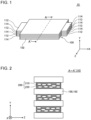
- Fig. 1 is a perspective view of a battery module 10 according to an embodiment.
- Fig. 2 is an A-A' cross-sectional schematic diagram of Fig. 1 .
- the X direction indicates a long direction of a battery cell 100 to be described later.
- the Y direction is orthogonal to the X direction.
- the Y direction indicates a thickness direction of the battery cell 100.
- the Z direction is orthogonal to both of the X direction and the Y direction.
- the Z direction indicates a short direction of the battery cell 100.
- a direction perpendicular to the Y direction is referred to as an XZ-plane direction, as necessary.
- the battery module 10 includes a plurality of battery cells 100 and a plurality of function materials 200.
- the plurality of battery cells 100 and the plurality of function materials 200 are alternately arrayed in the Y direction.
- each function material 200 is located between adjacent battery cells 100 in the Y direction.
- the battery module 10 is disposed with the Z direction being substantially parallel to a vertical direction and the X direction and the Y direction being substantially parallel to a horizontal direction perpendicular to the vertical direction.
- the battery module 10 is accommodated, for example, in an accommodation body which is not illustrated. The arrangement of the battery module 10 however is not limited to this example.
- a plurality of battery cells 100 are described.
- six battery cells 100 are schematically illustrated for description.
- the number of battery cells 100 included in the battery module 10 however is not limited to the example illustrated in Fig. 1 .
- Each battery cell 100 includes an exterior material 102, a positive electrode tab 112, and a negative electrode tab 114.
- the exterior material 102 seals a battery element which is not illustrated and electrolytic liquid which is not illustrated.
- the battery element includes a plurality of positive electrodes and a plurality of negative electrodes alternately stacked in the Y direction, and a separator located between a positive electrode and a negative electrode adjacent in the Y direction.
- the positive electrode tab 112 and the negative electrode tab 114 are drawn from opposite sides of the exterior material 102 in the X direction.
- the positive electrode tab 112 is electrically connected to the above-described plurality of positive electrodes.
- the negative electrode tab 114 is electrically connected to the above-described plurality of negative electrodes.
- the structure of the battery cell 100 however is not limited to the above-described example.
- a plurality of battery cells 100 arrayed in the Y direction are connected in series in order from a battery cell 100 on one side of the Y direction to a battery cell 100 on the other side of the Y direction.
- the positive electrode tab 112 and the negative electrode tab 114 drawn from one of two battery cells 100 adjacent in the Y direction, and the positive electrode tab 112 and the negative electrode tab 114 drawn from the other one of two battery cells 100 adjacent in the Y direction are directed oppositely to each other in the X direction.
- the positive electrode tab 112 drawn from one battery cell 100 and the negative electrode tab 114 drawn from the other battery cell 100 are joined to each other, for example, by laser welding.
- the positive electrode tab 112 drawn from the uppermost battery cell 100 in Fig 1 to the left side in Fig. 1 , and the negative electrode tab 114 drawn from the second battery cell 100 from top in Fig 1 to the left side in Fig. 1 are joined to each other.
- the positive electrode tab 112 drawn from the second battery cell 100 from top in Fig 1 to the right side in Fig. 1 , and the negative electrode tab 114 drawn from the third battery cell 100 from top in Fig. 1 to the right side in Fig. 1 are joined to each other.
- a joint portion between the positive electrode tab 112 and the negative electrode tab 114 on the left side in Fig. 1 and a joint portion between the positive electrode tab 112 and the negative electrode tab 114 on the right side in Fig. 1 are alternately disposed in a plurality of battery cells 100.
- Each function material 200 includes an elastic particle 210 and a binder 220.
- the elastic particle 210 is dispersed in the binder 220.
- the elastic particle 210 is a resinous hollow particle.
- the elastic particle 210 is formed of, for example, an acrylic styrene copolymer.
- the elastic modulus of the material of the elastic particle 210 is lower than the elastic modulus of the material of the binder 220.
- the elastic modulus of the material of the elastic particle 210 is, for example, equal to or more than 1 GPa and equal to or less than 20 GPa.
- the elastic particle 210 has a hollow substantially spherical shell shape.
- the particle diameter of the elastic particle 210 is, for example, equal to or more than 75 um and equal to or less than 300 um.
- the bore diameter of the elastic particle 210 is, for example, equal to or more than 50 um and equal to or less than 200 um.
- the material and structure of the elastic particle 210 however are not limited to this example.
- the elastic particles 210 illustrated in Fig. 2 are schematically depicted squeezed in the Y direction by the compression in the Y direction of the battery cells 100 adjacent to each other in the Y direction.
- the binder 220 is formed of a resin.
- the binder 220 is, for example, a cured acrylic resin.
- the binder 220 may be, for example, an ultraviolet cured acrylic resin.
- the binder 220 is a resin cured body.
- the material of the binder 220 however is not limited to this example.
- the binder 220 adheres to two battery cells 100 located on both sides of the binder 220 in the Y direction.
- the adhesion strength between the battery cell 100 and the binder 220 is, for example, approximately 10 kPa. The adhesion strength however is not limited to this example.
- the thickness of the function material 200 in the Y direction without being compressed by the battery cell 100 in the Y direction is, for example, equal to or more than 0.10 mm and equal to or less than 1.5 mm.
- the thickness of the function material 200 in the Y direction however is not limited to this example.
- the porosity of a portion of the function material 200 not occupied by the elastic particle 210 is, for example, equal to or more than 60 vol% and equal to or less than 70 vol% with respect to a total volume of the function material 200.
- the porosity equal to or more than the lower limit value thereof allows the function material 200 to be easily compressed in the Y direction.
- the porosity equal to or less than the upper limit value thereof can improve the strength of the function material 200.
- the porosity however is not limited to this example.
- the porosity is measured, for example, by observation of a cross-section perpendicular to the X direction of the function material 200 based on a scanning electron microscope (SEM).
- the function material 200 functions as a fixing material for fixing the battery cell 100 arrayed in the Y direction.
- the battery module 10 may be applied with force from an outside, for example, by an impact to the battery module 10 or vibration of an automobile on which the battery module 10 is mounted. In the embodiment, even when such force is applied to the battery module 10, shear of each battery cell 100 in the XZ-plane direction can be reduced by the function material 200.
- the function material 200 functions as a fixing material for fixing a plurality of positive electrodes and a plurality of negative electrodes disposed inside each exterior material 102.
- the function material 200 is compressed in the Y direction by battery cells 100 adjacent to each other in the Y direction.
- the function material 200 is elastically deformable in the Y direction by the elastic particle 210. Accordingly, each battery cell 100 receives pressurizing force from the function material 200.
- shear of a plurality of positive electrodes and a plurality of negative electrodes disposed inside the exterior material 102 in the XZ-plane direction can be reduced by the pressurizing force from the function material 200.
- the function material 200 functions as a buffer material to deform according to the swollenness of the battery cell 100 in the Y direction.
- the battery cell 100 may be swollen in the Y direction by charging the battery cell 100.
- the function material 200 is elastically deformable in the Y direction by the elastic particle 210. Accordingly, when the battery cell 100 is swollen in the Y direction, the function material 200 can be contracted in the Y direction according to the swollenness of the battery cell 100 in the Y direction.
- the compression force deflection at 25 °C and 10 % deflection of the function material 200 may be, for example, equal to or more than 3.0 kPa and equal to or less than 10 kPa.
- a temperature of the function material 200 is approximately 25°C.
- the compression force deflection equal to or more than the above-described lower limit value can reduce shear of each battery cell 100 in the XZ-plane direction and shear of a plurality of positive electrodes and a plurality of negative electrodes provided inside each exterior material 102 in the XZ-plane direction.
- the compression force deflection equal to or less than the above-described upper limit value can reduce a load on the battery cell 100 and loads on a plurality of positive electrodes and a plurality of provided inside each exterior material 102 due to compression of the function material 200 in the Y direction.
- the compression force deflection at 70 °C and 70 % deflection of the function material 200 may be, for example, equal to or more than 0.40 MPa and equal to or less than 0.60 MPa.
- a temperature of the function material 200 is approximately 70°C.
- the compression force deflection equal to or more than the above-described lower limit value can reduce shear of each battery cell 100 in the XZ-plane direction and shear of a plurality of positive electrodes and a plurality of negative electrodes provided inside each exterior material 102 in the XZ-plane direction.
- the compression force deflection equal to or less than the above-described upper limit value can reduce a load on the battery cell 100 and loads on a plurality of positive electrodes and a plurality of disposed inside each exterior material 102 due to compression of the function material 200 in the Y direction.
- Figs. 3 and 4 are diagrams illustrating a method of manufacturing the battery module 10 according to the embodiment.
- the battery module 10 according to the embodiment is manufactured as described below.
- the Y direction is substantially parallel to the vertical direction
- the X direction and the Z direction are substantially parallel to the horizontal direction.
- the tip end side of the arrow indicating the Y direction is an upper side of the vertical direction
- the base end side of the arrow indicating the Y direction is a lower side of the vertical direction.
- slurry 200' including the elastic particle 210 and the binder 220 is prepared.
- the slurry 200' is applied onto the upper surface of the exterior material 102.
- the slurry 200' is dripped from a nozzle 310 located above the exterior material 102.
- the moving of the nozzle 310 accordingly allows the slurry 200' to be applied onto a desired area of the upper surface of the exterior material 102.
- a formation range of the function material 200 can be easily adjusted as compared with when a compression pad such as a urethane sheet is cut into a predetermined size according to the size of an upper surface of the exterior material 102, and is attached on the upper surface of the exterior material 102.
- the embodiment does not require peeling off a sheet such as PET film from a compression pad, as compared with a case of using a compression pad such as a urethane sheet.
- a manufacturing time of the battery module 10 in the embodiment can be accordingly shorter than when using a compression pad.
- the workability for manufacturing the battery module 10 can be accordingly improved in the embodiment.
- the slurry 200' is applied onto an area equal to or more than 75 % and equal to or less than 100 % of the upper surface of the exterior material 102.
- the slurry 200' is irradiated with an ultraviolet ray 322.
- the ultraviolet ray 322 is irradiated from a light source 320 located above the battery cell 100.
- the binder 220 is cured by the ultraviolet ray 322.
- the slurry 200' is thus the function material 200.
- the function material 200 adheres to the upper surface of the exterior material 102.
- the method of curing the binder 220 is not limited to light curing illustrated in Fig. 4 .
- the binder 220 may be cured by thermal curing.
- another battery cell 100 is stacked on the upper surface side of the battery cell 100 on which the function material 200 is formed.
- the upper surface of the function material 200 and the lower surface of the other battery cell 100 are adhere to each other.
- the adhesion strength between the lower surface of the function material 200 and the upper surface of the battery cell 100 located below the function material 200, and the adhesion strength between the upper surface of the function material 200 and the lower surface of the other battery cell 100 located above the function material 200 are substantially equal.
- the function material 200 is formed on the upper surface of the other battery cell 100 similarly to the method described by using Figs. 3 and 4 .
- a predetermined number of battery cells 100 and function materials 200 are alternately stacked in the Y direction, and a plurality of the battery modules 10 are manufactured.
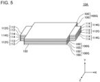
- Fig. 5 is a perspective view of a battery module 10A according to a variant.
- the battery module 10A according to the variant is similar to the battery module 10 according to the embodiment except the following point.
- the battery module 10A includes a plurality of cell groups 100G.
- Fig. 5 schematically illustrates three cell groups 100G for description.
- the number of cell groups 100G included in the battery module 10A however is not limited to the example illustrated in Fig. 5 .
- Each cell group 100G includes two battery cells 100.
- the number of battery cells 100 included in each cell group 100G however is not limited to two, and may be three or more.
- Each cell group 100G includes a positive electrode tab group 112G and a negative electrode tab group 114G.
- the positive electrode tab group 112G includes a plurality of positive electrode tabs 112 drawn from a plurality of battery cells 100 included in each cell group 100G.
- the negative electrode tab group 114G includes a plurality of negative electrode tabs 114 drawn from a plurality of battery cells 100 included in each cell group 100G.
- a plurality of battery cells 100 included in each cell group 100G are connected in parallel.
- a plurality of cell groups 100G stacked in the Y direction are connected in series in order from a cell group 100G on one side in the Y direction to a cell group 100G on the other side in the Y direction.
- the positive electrode tab group 112G and the negative electrode tab group 114G drawn from one of two cell groups 100G adjacent to each other in the Y direction, and the positive electrode tab group 112G and the negative electrode tab group 114G drawn from the other one of the two cell groups 100G adjacent to each other in the Y direction are directed oppositely to each other in the X direction.
- the positive electrode tab group 112G drawn from one cell group 100G and the negative electrode tab group 114G drawn from the other cell group 100G are joined to each other, for example, by laser welding.
- the negative electrode tab group 114G drawn from the second cell group 100G from top in Fig. 5 to the left side in Fig. 5 are joined to each other.
- a joint portion between the positive electrode tab group 112G and the negative electrode tab group 114G on the left side in Fig. 5 and a joint portion between the positive electrode tab group 112G and the negative electrode tab group 114G on the right side in Fig. 5 are alternately disposed in a plurality of cell groups 100G.
- the function material 200 may be provided between adjacent battery cells 100 in the Y direction.
- the workability for manufacturing the battery module 10A can be accordingly improved also in the variant, similarly to the embodiment.
Landscapes
- Chemical & Material Sciences (AREA)
- Chemical Kinetics & Catalysis (AREA)
- Electrochemistry (AREA)
- General Chemical & Material Sciences (AREA)
- Engineering & Computer Science (AREA)
- Manufacturing & Machinery (AREA)
- Battery Mounting, Suspending (AREA)
Abstract
Description
- The present invention relates to a battery module, and a method of manufacturing a battery module.
- In recent years, various battery modules including a plurality of battery cells have been developed. In a battery module, a plurality of the battery cells are arrayed in a predetermined direction.
- Patent Document 1 describes one example of a battery module. The battery module includes a spacer located between adjacent battery cells. The spacer is formed of a thermosetting resin.
- Patent Document 2 describes one example of a battery module. The battery module includes a spacer located between adjacent battery cells. The spacer includes a packaging body and a plurality of granular bodies. The plurality of granular bodies are accommodated in the packaging body.
- Patent Document 3 describes one example of a battery module. The battery module includes an elastic adhesive. The elastic adhesive is located between adjacent battery modules.
-
- Patent Document 1:
Japanese Patent Application Publication No. 2010-097693 - Patent Document 2:
Japanese Patent Application Publication No. 2014-072055 - Patent Document 3: International Publication No.
WO2018/163708 - A compression pad such as a urethane sheet may be provided between adjacent battery cells. In use of the compression pad, however, a size of the compression pad needs to be changed according to a size of a battery cell. Specifically, a relatively large size of the battery cell results in also increase in the size of the compression pad. In this case, the handling of the compression pad may be difficult due to a predetermined factor such as static electricity. A use of the compression pad may also require peeling off a sheet such as polyethylene terephthalate (PET) film disposed on one surface of the compression pad. The compression pad provided between adjacent battery cells may accordingly decrease workability for manufacturing a battery module.
- One example of an object of the present invention is to improve workability for manufacturing a battery module. Another object of the present invention will be clarified from description of the present specification.
- One aspect of the present invention is as follows.
- [1] A battery module including:
- a plurality of battery cells; and
- a function material located between the adjacent battery cells, wherein
- the function material includes an elastic particle, and a binder in which the elastic particle is dispersed.
- [2] The battery cell according to [1], wherein
- a compression force deflection at 25 °C and 10 % deflection of the function material is equal to or more than 3.0 kPa and equal to or less than 10 kPa, and
- the compression force deflection at 70 °C and 70 % deflection of the function material is equal to or more than 0.40 MPa and equal to or less than 0.60 MPa.
- [3] The battery module according to [1] or [2], wherein
the elastic particle is a resinous hollow particle. - [4] The battery module according to any one of [1] to [3], wherein
the binder is an acrylic resin. - [5] A method of manufacturing a battery module, including:
- a step of applying slurry onto a battery cell, the slurry including an elastic particle and a binder; and
- a step of curing the binder.
- [6] The method of manufacturing a battery module according to [5], wherein,
- after the step of curing the binder, a compression force deflection at 25 °C and 10 % deflection of a function material including the elastic particle and the binder is equal to or more than 3.0 kPa and equal to or less than 10 kPa, and,
- after the step of curing the binder, the compression force deflection at 70 °C and 70 % deflection of the function material is equal to or more than 0.40 MPa and equal to or less than 0.60 MPa.
- [7] The method of manufacturing a battery module according to [5] or [6], wherein
the elastic particle is a resinous hollow particle. - [8] The method of manufacturing a battery module according to any one of [5] to [7], wherein
the binder is an acrylic resin. - [9] The method of manufacturing a battery module according to any one of [5] to [8], wherein,
in the step of curing the binder, the binder is cured by irradiating the binder with light. - According to the above-described aspect of the present invention, workability for manufacturing a battery module can be improved.
-
-
Fig. 1 is a perspective view of a battery module according to an embodiment. -
Fig. 2 is an A-A' cross-sectional schematic diagram ofFig. 1 . -
Fig. 3 is a diagram illustrating a method of manufacturing a battery module according to the embodiment. -
Fig. 4 is a diagram illustrating the method of manufacturing a battery module according to the embodiment. -
Fig. 5 is a perspective view of a battery module according to a variant. - Hereinafter, an embodiment and a variant according to the present invention are described by using the accompanying drawings. In all drawings, a similar component is assigned with a similar reference sign, and description thereof is omitted, as appropriate.
-
Fig. 1 is a perspective view of abattery module 10 according to an embodiment.Fig. 2 is an A-A' cross-sectional schematic diagram ofFig. 1 . - In each figure, for description, an X direction, a Y direction, and a Z direction are illustrated. The X direction indicates a long direction of a
battery cell 100 to be described later. The Y direction is orthogonal to the X direction. The Y direction indicates a thickness direction of thebattery cell 100. The Z direction is orthogonal to both of the X direction and the Y direction. The Z direction indicates a short direction of thebattery cell 100. Hereinafter, a direction perpendicular to the Y direction is referred to as an XZ-plane direction, as necessary. - As illustrated in
Figs. 1 and 2 , thebattery module 10 includes a plurality ofbattery cells 100 and a plurality offunction materials 200. The plurality ofbattery cells 100 and the plurality offunction materials 200 are alternately arrayed in the Y direction. Thus, eachfunction material 200 is located betweenadjacent battery cells 100 in the Y direction. For example, thebattery module 10 is disposed with the Z direction being substantially parallel to a vertical direction and the X direction and the Y direction being substantially parallel to a horizontal direction perpendicular to the vertical direction. Thebattery module 10 is accommodated, for example, in an accommodation body which is not illustrated. The arrangement of thebattery module 10 however is not limited to this example. - With reference to
Fig. 1 , a plurality ofbattery cells 100 are described. InFig. 1 , sixbattery cells 100 are schematically illustrated for description. The number ofbattery cells 100 included in thebattery module 10 however is not limited to the example illustrated inFig. 1 . - Each
battery cell 100 includes anexterior material 102, apositive electrode tab 112, and anegative electrode tab 114. Theexterior material 102 seals a battery element which is not illustrated and electrolytic liquid which is not illustrated. The battery element includes a plurality of positive electrodes and a plurality of negative electrodes alternately stacked in the Y direction, and a separator located between a positive electrode and a negative electrode adjacent in the Y direction. Thepositive electrode tab 112 and thenegative electrode tab 114 are drawn from opposite sides of theexterior material 102 in the X direction. Thepositive electrode tab 112 is electrically connected to the above-described plurality of positive electrodes. Thenegative electrode tab 114 is electrically connected to the above-described plurality of negative electrodes. The structure of thebattery cell 100 however is not limited to the above-described example. - In the embodiment, a plurality of
battery cells 100 arrayed in the Y direction are connected in series in order from abattery cell 100 on one side of the Y direction to abattery cell 100 on the other side of the Y direction. Specifically, thepositive electrode tab 112 and thenegative electrode tab 114 drawn from one of twobattery cells 100 adjacent in the Y direction, and thepositive electrode tab 112 and thenegative electrode tab 114 drawn from the other one of twobattery cells 100 adjacent in the Y direction are directed oppositely to each other in the X direction. On one side of the X direction of twobattery cells 100 adjacent to each other in the Y direction, thepositive electrode tab 112 drawn from onebattery cell 100 and thenegative electrode tab 114 drawn from theother battery cell 100 are joined to each other, for example, by laser welding. For example, thepositive electrode tab 112 drawn from theuppermost battery cell 100 inFig 1 to the left side inFig. 1 , and thenegative electrode tab 114 drawn from thesecond battery cell 100 from top inFig 1 to the left side inFig. 1 are joined to each other. Thepositive electrode tab 112 drawn from thesecond battery cell 100 from top inFig 1 to the right side inFig. 1 , and thenegative electrode tab 114 drawn from thethird battery cell 100 from top inFig. 1 to the right side inFig. 1 are joined to each other. Thus, a joint portion between thepositive electrode tab 112 and thenegative electrode tab 114 on the left side inFig. 1 and a joint portion between thepositive electrode tab 112 and thenegative electrode tab 114 on the right side inFig. 1 are alternately disposed in a plurality ofbattery cells 100. - With reference to
Fig. 2 , a plurality offunction materials 200 are described. - Each
function material 200 includes an elastic particle 210 and a binder 220. The elastic particle 210 is dispersed in the binder 220. - In the embodiment, the elastic particle 210 is a resinous hollow particle. The elastic particle 210 is formed of, for example, an acrylic styrene copolymer. For example, the elastic modulus of the material of the elastic particle 210 is lower than the elastic modulus of the material of the binder 220. The elastic modulus of the material of the elastic particle 210 is, for example, equal to or more than 1 GPa and equal to or less than 20 GPa. In the embodiment, the elastic particle 210 has a hollow substantially spherical shell shape. The particle diameter of the elastic particle 210 is, for example, equal to or more than 75 um and equal to or less than 300 um. The bore diameter of the elastic particle 210 is, for example, equal to or more than 50 um and equal to or less than 200 um. The material and structure of the elastic particle 210 however are not limited to this example. The elastic particles 210 illustrated in
Fig. 2 are schematically depicted squeezed in the Y direction by the compression in the Y direction of thebattery cells 100 adjacent to each other in the Y direction. - In the embodiment, the binder 220 is formed of a resin. Specifically, the binder 220 is, for example, a cured acrylic resin. The binder 220 may be, for example, an ultraviolet cured acrylic resin. In the example illustrated in
Fig. 2 , the binder 220 is a resin cured body. The material of the binder 220 however is not limited to this example. The binder 220 adheres to twobattery cells 100 located on both sides of the binder 220 in the Y direction. The adhesion strength between thebattery cell 100 and the binder 220 is, for example, approximately 10 kPa. The adhesion strength however is not limited to this example. - The thickness of the
function material 200 in the Y direction without being compressed by thebattery cell 100 in the Y direction is, for example, equal to or more than 0.10 mm and equal to or less than 1.5 mm. The thickness of thefunction material 200 in the Y direction however is not limited to this example. - The porosity of a portion of the
function material 200 not occupied by the elastic particle 210 is, for example, equal to or more than 60 vol% and equal to or less than 70 vol% with respect to a total volume of thefunction material 200. The porosity equal to or more than the lower limit value thereof allows thefunction material 200 to be easily compressed in the Y direction. The porosity equal to or less than the upper limit value thereof can improve the strength of thefunction material 200. The porosity however is not limited to this example. The porosity is measured, for example, by observation of a cross-section perpendicular to the X direction of thefunction material 200 based on a scanning electron microscope (SEM). - In the embodiment, the
function material 200 functions as a fixing material for fixing thebattery cell 100 arrayed in the Y direction. Thebattery module 10 may be applied with force from an outside, for example, by an impact to thebattery module 10 or vibration of an automobile on which thebattery module 10 is mounted. In the embodiment, even when such force is applied to thebattery module 10, shear of eachbattery cell 100 in the XZ-plane direction can be reduced by thefunction material 200. - In the embodiment, the
function material 200 functions as a fixing material for fixing a plurality of positive electrodes and a plurality of negative electrodes disposed inside eachexterior material 102. Thefunction material 200 is compressed in the Y direction bybattery cells 100 adjacent to each other in the Y direction. Thefunction material 200 is elastically deformable in the Y direction by the elastic particle 210. Accordingly, eachbattery cell 100 receives pressurizing force from thefunction material 200. Thus, shear of a plurality of positive electrodes and a plurality of negative electrodes disposed inside theexterior material 102 in the XZ-plane direction can be reduced by the pressurizing force from thefunction material 200. - In the embodiment, the
function material 200 functions as a buffer material to deform according to the swollenness of thebattery cell 100 in the Y direction. Thebattery cell 100 may be swollen in the Y direction by charging thebattery cell 100. As described above, thefunction material 200 is elastically deformable in the Y direction by the elastic particle 210. Accordingly, when thebattery cell 100 is swollen in the Y direction, thefunction material 200 can be contracted in the Y direction according to the swollenness of thebattery cell 100 in the Y direction. - The compression force deflection at 25 °C and 10 % deflection of the
function material 200 may be, for example, equal to or more than 3.0 kPa and equal to or less than 10 kPa. For example, in an initial state of thebattery module 10 or a discharge state of thebattery module 10, a temperature of thefunction material 200 is approximately 25°C. In this state, the compression force deflection equal to or more than the above-described lower limit value can reduce shear of eachbattery cell 100 in the XZ-plane direction and shear of a plurality of positive electrodes and a plurality of negative electrodes provided inside eachexterior material 102 in the XZ-plane direction. In the above-described state, the compression force deflection equal to or less than the above-described upper limit value can reduce a load on thebattery cell 100 and loads on a plurality of positive electrodes and a plurality of provided inside eachexterior material 102 due to compression of thefunction material 200 in the Y direction. - The compression force deflection at 70 °C and 70 % deflection of the
function material 200 may be, for example, equal to or more than 0.40 MPa and equal to or less than 0.60 MPa. For example, in a charge state of thebattery module 10, a temperature of thefunction material 200 is approximately 70°C. In this state, the compression force deflection equal to or more than the above-described lower limit value can reduce shear of eachbattery cell 100 in the XZ-plane direction and shear of a plurality of positive electrodes and a plurality of negative electrodes provided inside eachexterior material 102 in the XZ-plane direction. In the above-described state, the compression force deflection equal to or less than the above-described upper limit value can reduce a load on thebattery cell 100 and loads on a plurality of positive electrodes and a plurality of disposed inside eachexterior material 102 due to compression of thefunction material 200 in the Y direction. - The above-described compression force deflection is measured according to ASTM D3574.
-
Figs. 3 and 4 are diagrams illustrating a method of manufacturing thebattery module 10 according to the embodiment. Thebattery module 10 according to the embodiment is manufactured as described below. In description usingFigs. 3 and 4 , unless otherwise specified, the Y direction is substantially parallel to the vertical direction, and the X direction and the Z direction are substantially parallel to the horizontal direction. Unless otherwise specified, the tip end side of the arrow indicating the Y direction is an upper side of the vertical direction, and the base end side of the arrow indicating the Y direction is a lower side of the vertical direction. - First, slurry 200' including the elastic particle 210 and the binder 220 is prepared.
- Next, as illustrated in
Fig. 3 , the slurry 200' is applied onto the upper surface of theexterior material 102. In the example illustrated inFig. 3 , the slurry 200' is dripped from anozzle 310 located above theexterior material 102. The moving of thenozzle 310 accordingly allows the slurry 200' to be applied onto a desired area of the upper surface of theexterior material 102. For this reason, a formation range of thefunction material 200 can be easily adjusted as compared with when a compression pad such as a urethane sheet is cut into a predetermined size according to the size of an upper surface of theexterior material 102, and is attached on the upper surface of theexterior material 102. The embodiment does not require peeling off a sheet such as PET film from a compression pad, as compared with a case of using a compression pad such as a urethane sheet. A manufacturing time of thebattery module 10 in the embodiment can be accordingly shorter than when using a compression pad. The workability for manufacturing thebattery module 10 can be accordingly improved in the embodiment. For example, the slurry 200' is applied onto an area equal to or more than 75 % and equal to or less than 100 % of the upper surface of theexterior material 102. - Next, as illustrated in
Fig. 4 , the slurry 200' is irradiated with anultraviolet ray 322. In the example illustrated inFig. 4 , theultraviolet ray 322 is irradiated from alight source 320 located above thebattery cell 100. The binder 220 is cured by theultraviolet ray 322. The slurry 200' is thus thefunction material 200. Thefunction material 200 adheres to the upper surface of theexterior material 102. - The method of curing the binder 220 is not limited to light curing illustrated in
Fig. 4 . For example, the binder 220 may be cured by thermal curing. - Next, another
battery cell 100 is stacked on the upper surface side of thebattery cell 100 on which thefunction material 200 is formed. Thus, the upper surface of thefunction material 200 and the lower surface of theother battery cell 100 are adhere to each other. In this case, for example, the adhesion strength between the lower surface of thefunction material 200 and the upper surface of thebattery cell 100 located below thefunction material 200, and the adhesion strength between the upper surface of thefunction material 200 and the lower surface of theother battery cell 100 located above thefunction material 200 are substantially equal. Next, thefunction material 200 is formed on the upper surface of theother battery cell 100 similarly to the method described by usingFigs. 3 and 4 . Thus, a predetermined number ofbattery cells 100 andfunction materials 200 are alternately stacked in the Y direction, and a plurality of thebattery modules 10 are manufactured. -
Fig. 5 is a perspective view of abattery module 10A according to a variant. Thebattery module 10A according to the variant is similar to thebattery module 10 according to the embodiment except the following point. - The
battery module 10A according to the variant includes a plurality ofcell groups 100G.Fig. 5 schematically illustrates threecell groups 100G for description. The number ofcell groups 100G included in thebattery module 10A however is not limited to the example illustrated inFig. 5 . Eachcell group 100G includes twobattery cells 100. The number ofbattery cells 100 included in eachcell group 100G however is not limited to two, and may be three or more. Eachcell group 100G includes a positiveelectrode tab group 112G and a negativeelectrode tab group 114G. The positiveelectrode tab group 112G includes a plurality ofpositive electrode tabs 112 drawn from a plurality ofbattery cells 100 included in eachcell group 100G. The negativeelectrode tab group 114G includes a plurality ofnegative electrode tabs 114 drawn from a plurality ofbattery cells 100 included in eachcell group 100G. - A plurality of
battery cells 100 included in eachcell group 100G are connected in parallel. A plurality ofcell groups 100G stacked in the Y direction are connected in series in order from acell group 100G on one side in the Y direction to acell group 100G on the other side in the Y direction. Specifically, the positiveelectrode tab group 112G and the negativeelectrode tab group 114G drawn from one of twocell groups 100G adjacent to each other in the Y direction, and the positiveelectrode tab group 112G and the negativeelectrode tab group 114G drawn from the other one of the twocell groups 100G adjacent to each other in the Y direction are directed oppositely to each other in the X direction. On one side in the X direction of twocell groups 100G adjacent to each other in the Y direction, the positiveelectrode tab group 112G drawn from onecell group 100G and the negativeelectrode tab group 114G drawn from theother cell group 100G are joined to each other, for example, by laser welding. For example, the positiveelectrode tab group 112G drawn from theuppermost cell group 100G inFig. 5 to the left side inFig. 5 , and the negativeelectrode tab group 114G drawn from thesecond cell group 100G from top inFig. 5 to the left side inFig. 5 are joined to each other. The positiveelectrode tab group 112G drawn from thesecond cell group 100G from top inFig. 5 to the right side inFig. 5 , and the negativeelectrode tab group 114G drawn from thethird cell group 100G from top inFig. 5 to the right side inFig. 5 are joined to each other. Thus, a joint portion between the positiveelectrode tab group 112G and the negativeelectrode tab group 114G on the left side inFig. 5 and a joint portion between the positiveelectrode tab group 112G and the negativeelectrode tab group 114G on the right side inFig. 5 are alternately disposed in a plurality ofcell groups 100G. - Also in the variant illustrated in
Fig. 5 , similarly to the embodiment, thefunction material 200 may be provided betweenadjacent battery cells 100 in the Y direction. The workability for manufacturing thebattery module 10A can be accordingly improved also in the variant, similarly to the embodiment. - While the embodiment and the variant according to the present invention have been described with reference to the drawings, the embodiment and the variant are illustrative of the present invention, and various configurations other than the above-described configurations may be employed.
-
- 10, 10A
- Battery module
- 100
- Battery cell
- 100G
- Cell group
- 102
- Exterior material
- 112
- Positive electrode tab
- 112G
- Positive electrode tab group
- 114
- Negative electrode tab
- 114G
- Negative electrode tab group
- 200
- Function material
- 210
- Elastic particle
- 220
- Binder
- 310
- Nozzle
- 320
- Light source
- 322
- Ultraviolet ray
Claims (9)
- A battery module comprising:a plurality of battery cells; anda function material located between the adjacent battery cells, whereinthe function material includes an elastic particle, and a binder in which the elastic particle is dispersed.
- The battery cell according to claim 1, whereina compression force deflection at 25 °C and 10 % deflection of the function material is equal to or more than 3.0 kPa and equal to or less than 10 kPa, andthe compression force deflection at 70 °C and 70 % deflection of the function material is equal to or more than 0.40 MPa and equal to or less than 0.60 MPa.
- The battery module according to claim 1 or 2, wherein
the elastic particle is a resinous hollow particle. - The battery module according to any one of claims 1 to 3, wherein
the binder is an acrylic resin. - A method of manufacturing a battery module, comprising:a step of applying slurry onto a battery cell, the slurry including an elastic particle and a binder; anda step of curing the binder.
- The method of manufacturing a battery module according to claim 5, wherein,after the step of curing the binder, a compression force deflection at 25 °C and 10 % deflection of a function material including the elastic particle and the binder is equal to or more than 3.0 kPa and equal to or less than 10 kPa, and,after the step of curing the binder, the compression force deflection at 70 °C and 70 % deflection of the function material is equal to or more than 0.40 MPa and equal to or less than 0.60 MPa.
- The method of manufacturing a battery module according to claim 5 or 6, wherein
the elastic particle is a resinous hollow particle. - The method of manufacturing a battery module according to any one of claims 5 to 7, wherein
the binder is an acrylic resin. - The method of manufacturing a battery module according to any one of claims 5 to 8, wherein,
in the step of curing the binder, the binder is cured by irradiating the binder with light.
Applications Claiming Priority (1)
| Application Number | Priority Date | Filing Date | Title |
|---|---|---|---|
| JP2022085923A JP7738523B2 (en) | 2022-05-26 | 2022-05-26 | Battery module and method for manufacturing the battery module |
Publications (2)
| Publication Number | Publication Date |
|---|---|
| EP4283768A2 true EP4283768A2 (en) | 2023-11-29 |
| EP4283768A3 EP4283768A3 (en) | 2024-03-06 |
Family
ID=86605223
Family Applications (1)
| Application Number | Title | Priority Date | Filing Date |
|---|---|---|---|
| EP23175628.9A Pending EP4283768A3 (en) | 2022-05-26 | 2023-05-26 | Battery module, and method of manufacturing battery module |
Country Status (4)
| Country | Link |
|---|---|
| US (1) | US20230387546A1 (en) |
| EP (1) | EP4283768A3 (en) |
| JP (1) | JP7738523B2 (en) |
| CN (1) | CN117134065A (en) |
Citations (3)
| Publication number | Priority date | Publication date | Assignee | Title |
|---|---|---|---|---|
| JP2010097693A (en) | 2008-10-14 | 2010-04-30 | Toyota Motor Corp | Power storage device |
| JP2014072055A (en) | 2012-09-28 | 2014-04-21 | Lithium Energy Japan:Kk | Battery module |
| WO2018163708A1 (en) | 2017-03-07 | 2018-09-13 | 日産自動車株式会社 | Battery pack production method |
Family Cites Families (12)
| Publication number | Priority date | Publication date | Assignee | Title |
|---|---|---|---|---|
| JP2014179215A (en) * | 2013-03-14 | 2014-09-25 | Toshiba Corp | Secondary battery device |
| JP6528063B2 (en) * | 2015-02-26 | 2019-06-12 | 協立化学産業株式会社 | Method of manufacturing battery module |
| JP6894379B2 (en) * | 2016-09-30 | 2021-06-30 | 積水化学工業株式会社 | Thermally conductive thermally expandable resin composition, thermally conductive thermally expandable molded article, battery module, and battery pack |
| JP6883477B2 (en) * | 2017-06-13 | 2021-06-09 | 鹿島建設株式会社 | Hardened concrete |
| JP7069689B2 (en) * | 2017-12-19 | 2022-05-18 | 株式会社Gsユアサ | Charge control method of power storage element, state estimation method, life estimation method, manufacturing method of power storage system, and management device of power storage element |
| JP2020050841A (en) * | 2018-09-28 | 2020-04-02 | 積水化学工業株式会社 | Battery cushioning material |
| EP3951906A4 (en) * | 2019-03-29 | 2023-08-16 | Mitsui Chemicals, Inc. | Lithium ion battery stack |
| JP7032360B2 (en) * | 2019-08-27 | 2022-03-08 | イビデン株式会社 | Insulation sheet for assembled battery and assembled battery |
| CN111207173B (en) * | 2020-01-09 | 2021-11-16 | 苏州赛伍应用技术股份有限公司 | Buffering silica gel sheet used between electric cores of power battery pack, preparation method of buffering silica gel sheet and power battery pack comprising buffering silica gel sheet |
| JP2021111561A (en) * | 2020-01-14 | 2021-08-02 | 昭和電工マテリアルズ株式会社 | Elastic body, fixing member, and battery module |
| US12586830B2 (en) * | 2020-10-12 | 2026-03-24 | Lg Energy Solution, Ltd. | Battery module, battery pack, and vehicle |
| KR102927419B1 (en) * | 2022-02-10 | 2026-02-12 | 삼성에스디아이 주식회사 | Elastic sheet composition for all solid state battery, elastic sheet, and all solid state battery |
-
2022
- 2022-05-26 JP JP2022085923A patent/JP7738523B2/en active Active
-
2023
- 2023-05-17 US US18/318,923 patent/US20230387546A1/en active Pending
- 2023-05-18 CN CN202310561980.1A patent/CN117134065A/en active Pending
- 2023-05-26 EP EP23175628.9A patent/EP4283768A3/en active Pending
Patent Citations (3)
| Publication number | Priority date | Publication date | Assignee | Title |
|---|---|---|---|---|
| JP2010097693A (en) | 2008-10-14 | 2010-04-30 | Toyota Motor Corp | Power storage device |
| JP2014072055A (en) | 2012-09-28 | 2014-04-21 | Lithium Energy Japan:Kk | Battery module |
| WO2018163708A1 (en) | 2017-03-07 | 2018-09-13 | 日産自動車株式会社 | Battery pack production method |
Also Published As
| Publication number | Publication date |
|---|---|
| JP7738523B2 (en) | 2025-09-12 |
| CN117134065A (en) | 2023-11-28 |
| US20230387546A1 (en) | 2023-11-30 |
| EP4283768A3 (en) | 2024-03-06 |
| JP2023173580A (en) | 2023-12-07 |
Similar Documents
| Publication | Publication Date | Title |
|---|---|---|
| US11949062B2 (en) | Pressing jig for removing gas trap and method for manufacturing secondary battery using same | |
| EP2963724A1 (en) | Fuel cell device and manufacturing method for same | |
| EP4113683A1 (en) | Longitudinal constraints for energy storage devices | |
| CN110622346B (en) | Lithium metal secondary battery and method for manufacturing same | |
| CN217823188U (en) | Battery cell, battery and power consumption device | |
| US20110117419A1 (en) | Battery pack | |
| KR101826894B1 (en) | Electrode assembly and apparatus for manufacturing the same | |
| CN102687330B (en) | Fuel cell stack, method of manufacturing fuel cell stack, and method of replacing modules constituting fuel cell stack | |
| US9093684B2 (en) | Cylindrical secondary battery of improved safety | |
| CN110402502B (en) | Electric vehicle battery cell with solid-state electrolyte | |
| CN102460814A (en) | Energy storage device with unipolar and bipolar batteries electrically coupled in series and parallel | |
| KR102254264B1 (en) | Electrode assembly and method of manufacturing the same | |
| CN114946063A (en) | Pressing jig for battery cell including pressing pad and method of degassing battery cell using the same | |
| EP4283768A2 (en) | Battery module, and method of manufacturing battery module | |
| EP4485624A1 (en) | Battery pack with easy disassembly | |
| KR101464965B1 (en) | Manufacturing of Battery Cell by Curbed Shaped | |
| US12482891B2 (en) | Methods and apparatus to increase stacking pressure in battery cells | |
| KR101684396B1 (en) | Battery Cell Comprising Flexible Current Collector | |
| US20230223585A1 (en) | Battery and method of producing the same | |
| EP4216349A1 (en) | Battery, electrical device, and method and apparatus for manufacturing battery | |
| KR102089306B1 (en) | Secondary Battery Comprising Battery Case Having Fixing Protrusion Coupled to Fixing Hole of Electrode Tab in Rivet Structure | |
| KR102196118B1 (en) | Electrode Assembly Having Bonding Layer For Improving Hardness and Lithium Secondary Battery Comprising the Same | |
| US20250372795A1 (en) | Battery tape and battery having battery tape attached thereto | |
| US20250300321A1 (en) | Battery | |
| EP1830429B1 (en) | lead acid accumulator |
Legal Events
| Date | Code | Title | Description |
|---|---|---|---|
| PUAI | Public reference made under article 153(3) epc to a published international application that has entered the european phase |
Free format text: ORIGINAL CODE: 0009012 |
|
| STAA | Information on the status of an ep patent application or granted ep patent |
Free format text: STATUS: THE APPLICATION HAS BEEN PUBLISHED |
|
| AK | Designated contracting states |
Kind code of ref document: A2 Designated state(s): AL AT BE BG CH CY CZ DE DK EE ES FI FR GB GR HR HU IE IS IT LI LT LU LV MC ME MK MT NL NO PL PT RO RS SE SI SK SM TR |
|
| PUAL | Search report despatched |
Free format text: ORIGINAL CODE: 0009013 |
|
| AK | Designated contracting states |
Kind code of ref document: A3 Designated state(s): AL AT BE BG CH CY CZ DE DK EE ES FI FR GB GR HR HU IE IS IT LI LT LU LV MC ME MK MT NL NO PL PT RO RS SE SI SK SM TR |
|
| RIC1 | Information provided on ipc code assigned before grant |
Ipc: H01M 50/262 20210101ALI20240130BHEP Ipc: H01M 50/211 20210101AFI20240130BHEP |
|
| STAA | Information on the status of an ep patent application or granted ep patent |
Free format text: STATUS: REQUEST FOR EXAMINATION WAS MADE |
|
| 17P | Request for examination filed |
Effective date: 20240801 |
|
| RBV | Designated contracting states (corrected) |
Designated state(s): AL AT BE BG CH CY CZ DE DK EE ES FI FR GB GR HR HU IE IS IT LI LT LU LV MC ME MK MT NL NO PL PT RO RS SE SI SK SM TR |